Samsung Electronics Co RPMR500 Zigbee Module User Manual RP MR500 Manual final
Samsung Electronics Co Ltd Zigbee Module RP MR500 Manual final
UserManual.wiki
>
Samsung Electronics Co
>
RPMR500 User Manual
manual
Navigation menu
Upload a User Manual
Namespaces
Wiki Guide
HTML
PDF
Info
Views
User Manual
Discussion / Help
Navigation
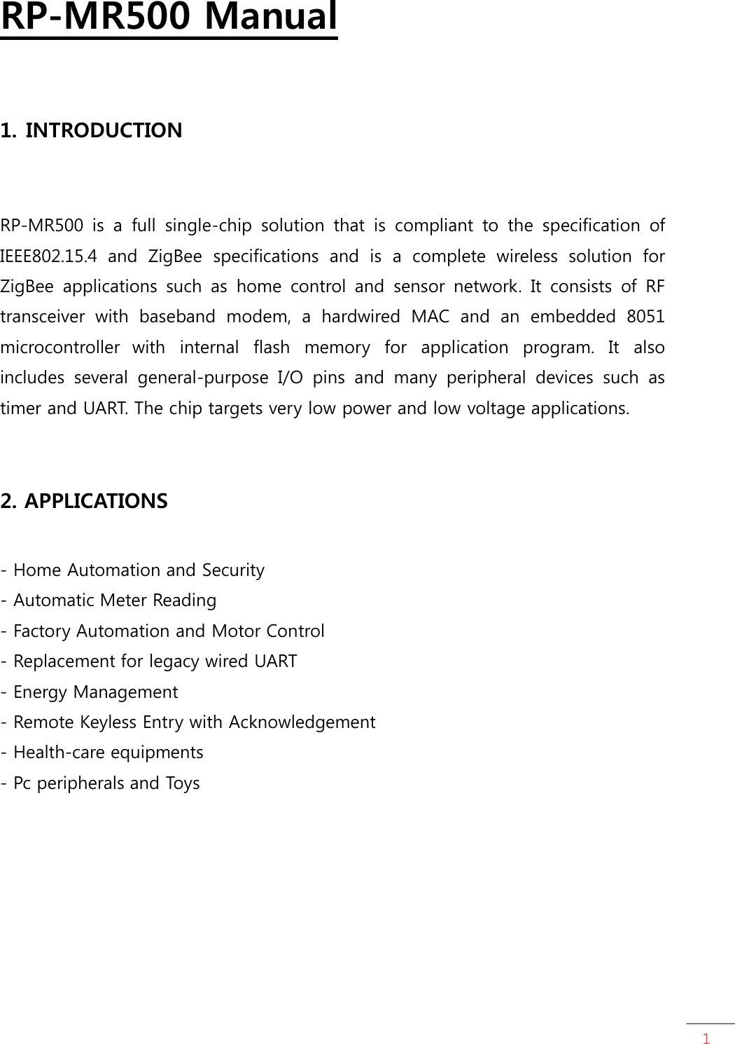
![56. PIN Description Terminal NAME Interface I/O Description 1 ACH0 Analog I/O Sensor ADC input 2 ACH1 Analog I/O Sensor ADC input 3 ACH2 Analog I/O Sensor ADC input 4 ACH3 Analog I/O Sensor ADC input 5 AVDD_1.5V Power I/O 1.5V Power Supply input/output 6 AGND Ground - RF Ground 7 MS0 Digital I Mode select 8 MS1 Digital I Mode select 9 MS2 Digital I Mode select 10 MSV Digital I Mode select of voltage(0=1.5V) 11 RESETB Digital I Reset (Active Low) 12 3V_IN Power I 3V Power supply 13 DGND Ground - Ground for digital core and I/O 14 P1[7] Digital O Port P1.7GPO/P0AND/TRSW 15 P1[6] Digital B Port P1.6/TRSWB 16 P1[5] Digital B Port P1.5 17 P1[4] Digital B Port P1.4 /QUADZB/Sleep Timer OSC Buffer Input. 18 P1[3] Digital B Port P1.3/QUADZA/Sleep Timer OSC Buffer Output/RTCLKOUT 19 P1[2] Digital B Port P1.2 20 P1[1] Digital B Port P1.1/TXD1 21 P1[0] Digital B Port P1.0/RXD1 22 P3[7] Digital B Port P3.7/12mA Drive capability /PWM3/CTS1/SPICSN(slave only) 23 P3[6] Digital B Port P3.6/12 mA Drive capability /PWM2/RTS1/SPICLK](https://usermanual.wiki/Samsung-Electronics-Co/RPMR500/User-Guide-1657087-Page-5.png)
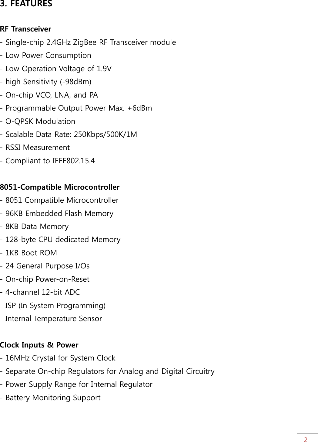
![6Terminal NAME Interface I/O Description 24 P3[5] Digital B Port P3.5/T1/CTS0/QUADYB/SPIDO 25 P3[4] Digital B Port P3.4/T0/RTS0/QUADYA/SPIDI 26 P3[3] Digital B Port P3.3/INT1(active low) 27 P3[2] Digital B Port P3.2/INT0(active low) 28 P3[1] Digital B Port P3.1/TXD0/QUADXB 29 P3[0] Digital B Port P3.0/RXD0/QUADXA 30 DGND Ground - Ground for digital core and I/O 31 DVDD_1.5V Power I/O 1.5V Power Supply input/output 32 P0[7] Digital B Port P0.7/I2STX_MCLK 33 P0[6] Digital B Port P0.6/I2STX_BCLK 34 P0[5] Digital B Port P0.5/I2STX_LRCK 35 P0[4] Digital B Port P0.4/I2STX_DO 36 P0[3] Digital B Port P0.3/I2SRX_MCLK 37 P0[2] Digital B Port P0.2/I2SRX_BCLK 38 P0[1] Digital B Port P0.1/I2SRX_LRCK 39 P0[0] Digital B Port P0.0/I2SRX_DI 40 NC NC - No Connection 41 NC NC - No Connection 42 AGND Ground - RF Ground 43 DGND Ground - Ground for digital core and I/O 44 DGND Ground - Ground for digital core and I/O 45 AGND Ground - RF Ground 7. Contact Information RadioPulse Inc. 3rd fl., Hans II bldg., 111-6 Seongnae-dong, Gangdong-gu, Seoul, 134-883, Korea Tel : +82 2 478 2963~5 Fax : +82 2 478 2966~7](https://usermanual.wiki/Samsung-Electronics-Co/RPMR500/User-Guide-1657087-Page-6.png)