Samsung Electronics Co S760 Notebook Computer User Manual Version 0 Maverick Change from Matrix
Samsung Electronics Co Ltd Notebook Computer Version 0 Maverick Change from Matrix
Contents
- 1. user manual 1 of 3
- 2. user manual 2 of 3
- 3. user manual 3 of 3
user manual 3 of 3
64 Using the Modem
ATDTS0Recalls the stored phone number as AT&Z0 by tone dial
ATDPS0Recalls the stored phone number as AT&Z0 by pulse dial
AT+MS=X Sets protocol for modem connection
(X=V90, V34)
AT+MS=V90 (default setting)
Try to connect with V.90 (max 56 Kbps)
AT+MS=V34
Try to connect with V.34 (max 33.6 Kbps)

Using the LAN 65
Using the LAN
Ideal for customers who want basic 10/100 connectivity. Delivers industry-leading
performance through Intel's latest 82559 chip design. Common drivers and Intel's
PROSet utility enable widespread compatibility and ease of installation.
Installing the LAN Driver in Windows Me
Before you begin verify that the "3Com 10/100 Mini PCI Ethernet Adapter" is installed
otherwise you will have to install it.
Install the LAN Driver
Windows Me has its own PCI Ethernet Adapter driver, simply install the LAN driver
according to the instructions below.
1. Start > Settings > Control Panel > System, double-click the system icon.
2. Click the Device Manager tab.
3. Double-click Network Adapters in the list area.
4. Click the Driver tab,thenclickUpdate Driver.
5. Select "Specify the location of the driver (Advanced)" and click Next.
6. Select "Search for a better driver than the one your device is using "Removable
Media (Floppy, CD-ROM...)" and "Specify a location" then click Browse
(Recommended)".
Select the D:\Driver\LanDrv\WinMe from your CD-ROM. and after click Next.
7. Click Next.
8. Click Finish. (Windows has finished installing an updated driver for your hardware
device)
9. Click Yes, to restart your computer and complete the driver installation.
Configuring Network Environment
1. After you complete the installation of the Network Adapter Driver, double-click the
Network icon in the control panel.
66 Using the LAN
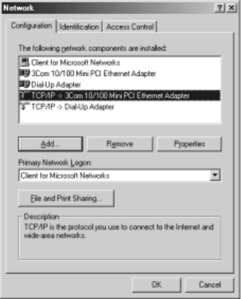
2. Click the Network Configuration tab, then ensure that "3Com 10/100 Mini PCI
Adapter" is Installed.
Figure 40. Installing the LAN Driver
3. Select TCP/IP -> 3Com 10/100 Mini PCI Ethernet Adapter in the list of network
components in the installed list, and click Properties.
4. From the TCP/IP Properties, click the IP Address tab. Select Specify an IP address
and then enter your IP address and the appropriate subnet mask.
If you use DHCP server, select "Obtain an IP address automatically".
5. Click the Gateway tab, then enter gateway address in the New gateway and Click
Add.
If you use DHCP server, this process is not needed.
6. Click the DNS Configuration tab, then select Enable DNS, and enter the host name
in the Host, enter the domain name in the Domain and DNS server address in the
DNS server Search Order.
Click "Add". If you use DHCP server, this process is not needed.
7. If you finish the TCP/IP set-up, click OK.
8. From the Network dialog box, click Add.

Using the LAN 67
9. From the Select Network Component type dialog box, select protocol and then
Click Add.
10. From the Select Network Protocol dialog box, select Microsoft in the
Manufactures list and then select IPX/SPX-compatible Protocol.ClickOK.
11.Repeat 8 and 9. Select Microsoft in the Manufactures list, and then selectNetBEUI.
Click OK.
12.Click Network "Identification" tab, type in anything you wish to identify this
computer in Computer Name,Workgroup,Computer Description.Keepinmind
that each Computer Name is unique on a network.
13.When you finish the network set-up, click OK from the Network dialog box.
14.Restart your computer to update the system.
Installing the LAN Driver in Windows 98
You can install the LAN driver as shown in the following.
LAN Driver Installation
Windows 98 has its own Intel (R) PRO/100+ PCI adapter driver, but install the LAN
driver according to the instructions below.
1. From the Control Panel, double-click the System icon.
2. Click the Device Manager tab.
3. Double-click Other Devices or Network Adapters in the list area.
4. Double-click a PCI Ethernet Controller (or Intel (R) PRO/100+ PCI adapter).
5. Click the Driver tab, then click Update Driver.
6. Click Next at the Update Device Driver Wizard.
7. Select "Display a list of all the drivers in a specific location..." and click Next.
8. Click Disk and select Have Disk.
9. Insert the Intel PRO/100+ adapter disk or System Software CD and select Specify
a location, then enter the appropriate drive for your disk media (A:, D:, etc.), and
Click OK.

68 Using the LAN
10.The Update Wizard displays the message that it has found the driver and select
Intel (R) PRO/100+ PCI Adapter,thenClickOK.
11.From the Update Device Driver Wizard, Click Next.
If a dialog box displays file not found message, enter the driver directory,
and click
OK
.
12.From the Update Wizard, Click Finish.
13.Restart your computer when prompted to update your computer.
Configuring Network Environment
1. If you complete installing Network Adapter driver, from the control panel, double-
click the Network icon.
2. Click Network Configuration tab, then ensure that Intel (R) PRO/100+ PCI
Adapter is installed.
3. Select TCP/IP >Intel (R) PRO/100+ PCI Adapter in the The following network
components are installed list, and click Properties.
4. From the TCP/IP Properties, click the IP Address tab. Select Specify an IP address
and then enter your IP address and the appropriate subnet mask. If you use DHCP
server, select Obtain an IP address automatically.
5. Click the Gateway tab, then enter gateway address in the New gateway and Click
Add. If you use DHCP server, this process is not needed.
6. Click the DNS Configuration tab, then select Enable DNS, and enter the host name
in the Host, domain name in the Domain and DNS server address in the DNS server
Search Order.ClickAdd. If you use DHCP server, this process is not needed.
7. If you finish the TCP/IP setup, click OK.
8. From the Network dialog box, click Add.
9. From the Select Network Component type dialog box, select protocol, click Add.
10.From the Select Network Protocol dialog box, select Microsoft in the Manufactures
list and then select IPX/SPX-compatible Protocol, click OK.
11.Repeat 8 and 9. Select Microsoft in the Manufacturers list, and then select
NetBEUI, click OK.
12.If you finish the network setup, from Network dialog box, click OK.
13.Restart your computer to update the system.
Windows Me Sound Card Driver Installation 69
Windows Me Sound Card Driver Installation
When you add a new sound device Windows Me will recognize the addition of PCI
Multimedia Audio Device and start the driver installation process automatically.
Sound Card Driver Installation
When Windows ME automatically detects a 'PCI Multimedia Audio Device', click the
Next and Finish buttons.
1. Insert the System Utility CD.
2. Click the Star' button, point to Settings and then click Control Panel.
•Double-Click System icon.
•Choose Device Manager tab.
•Select Sound, Video and Game controller and ESS Allegro PCI Audio (WDM).
•Click Properties.
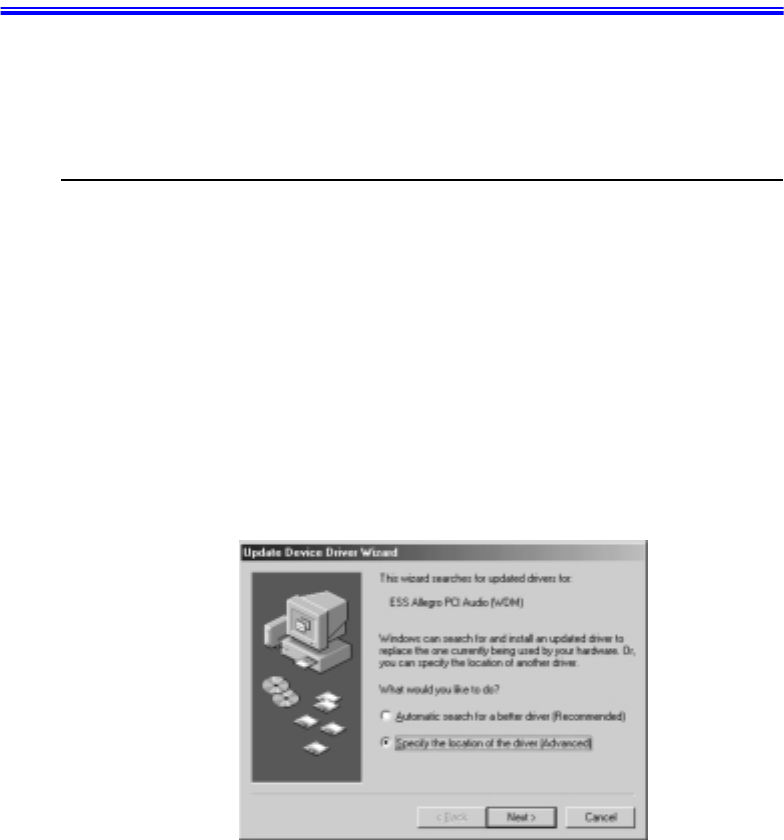
3. Click Update Driver.
4. Select Specify the location of the driver (Advanced) and click Next.
Figure 41. Device Driver Update Wizard (Specify Location)
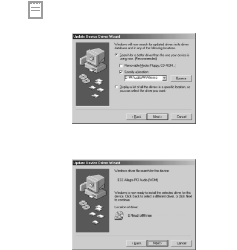
5. Check Specify a location and type D:\Audio\Winme and then click Next.
70 Windows Me Sound Card Driver Installation
('D:\' may be the name of your CD-ROM Drive. If not type in the actual
drive letter of your CD-ROM Drive).
Figure 42. Device Driver Update Wizard (File Location)
6. ClickNext when the dialog appears saying that Windows is now ready to install
the driver.
Figure 43. Device Driver Update Wizard (Install Start)
Windows Me Sound Card Driver Installation 71
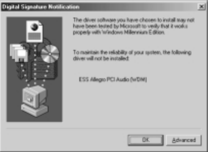
7. Click OK when the dialog appears saying that Windows has finished installing.
Figure 44. Device Driver Update Wizard (Install Complete)
8. Restart the system to update your files.

72 Using System Setup
Using System Setup
The System Setup program enables you to configure your computer hardware and set
security and power-savings options. The settings you choose are stored in battery-
maintained CMOS memory that saves the information even when the computer’s
power is turned off. When your computer is turned back on, it is configured with the
values found in this memory.
Run System Setup if you get a message prompting you to run the program. You may
also want to run System Setup, particularly the first time you use your computer, to set
the time and date, use security or power-management features, or alter the settings of
other features.
Your computer’s version of System Setup may not include all the fields
listed here or may include additional fields. Field names and order of
appearance can vary according to the version of the BIOS (basic input/
output system) on your computer.
You can use the configuration listing at the back of this manual to record information
specific to your computer. (See”Recording the Computer Hardware Configuration”on
page 133.) Fill it out as you complete your System Setup configuration. This list helps
you describe your computer if you must contact your authorized reseller for service or
product information.
Starting System Setup
To start System Setup, turn on your computer and then press <F2> when prompted.
The System Setup screen appears.
The top of the System Setup screen has a menu bar with the selections listed in Table 4.
Table 4. System Setup Menus
Menu Function
Main Changes the basic system configuration.
Advanced Configures advanced features on your computer.
Security Enables security features, including passwords
and backup and virus-check reminders.
Power Configures power-management features.

Using System Setup 73
To open a menu, use the left or right arrow keys to select the menu name and then press
<Enter>.
Table 5 lists the keys you can use to navigate through System Setup.
Table 5. System Setup Navigation Keys
Boot Specifies the order of boot devices and
configures boot features.
Exit Specifies how to exit System Setup.
Navigation Key Alternate
Key Function
<F1> <Alt+H> Displays the General Help window.
<Esc> Exits the current menu.
<Left Arrow> and
<Right Arrow>
keys
Keypad arrow
keys
Select a different menu. Pressing <ESC> at the Main
menu brings you to the Exit menu.
<Up Arrow> and
<Down Arrow>
keys
Keypad arrow
keys
Move the cursor up and down between fields.
<Tab> Moves the cursor forward through the cells for a
highlighted field. If the field has only one cell, the
<Tab> key moves the cursor down to the next field.
<Tab+Shift> Moves the cursor backward through the cells for a
highlighted field. If the field has only one cell, the
<Tab+Shift> key combination moves the cursor up to
the previous field.
<Home> <PgUp> Moves the cursor to the field at the top of the window.
<End> <PgDn> Moves the cursor to the field at the bottom of the
window.
<F5> <-> Scrolls backwards through the options for the
highlighted field.
<F6> <+> or
<Space>
Scrolls forward through the options for the highlighted
field.
<F9> Sets the parameters for the current menu to their
default values.
<F10> Sets the parameters for the current menu to their
previous values.
<Enter> Executes commands or opens a submenu.

74 Using System Setup
A pointer symbol appearing to the left of a field indicates that you can open a submenu
from this field. A submenu contains additional options for a field. To open a submenu,
highlight the field and press <Enter>. Use the same keys to enter values and move from
field to field within submenus as you use within menus.
When you highlight a field, information about the field appears on the right side of the
screen. System Setup also provides a General Help screen that can be opened from any
menu by pressing <F1> or <Alt+H>. The General Help screen lists the navigation keys
with their corresponding alternates and functions.
When a scroll bar appears to the right of a help window, more information is available
than can be displayed in the window. Use the <PgUp> and <PgDn> keys or the <Up
Arrow> and <Down Arrow> keys to scroll through the entire help document. Press
<Home> to display the first page, or press <End> to go to the last page. To exit the help
window, press <Enter> or <Esc>.
If your computer will not boot after you have changed settings in System Setup and
exited the program, reboot and press <F2> to reenter System Setup. Once in System
Setup, you can try to change the values that caused your computer boot to fail. If the
problem persists, press <F9> to load the default values.
Main Menu
When you open System Setup, the Main menu appears. You can make changes to your
computer’s basic system configuration from this menu. The fields displayed in this
menu are described below.
System Time:
Sets your computer to the time that you specify, usually the current time. Enter the
hour, minute, and second in the format hh:mm:ss. Use a 24-hour clock.Use the tab key
to move between the hour, minute, and second cells. Use the hyphen key <-> or
<Space> bar to decrease or increase the numbers.
System Date:
Sets your computer to the date that you specify, usually the current date. Enter the
month, day, and year in the format mm:dd:yyyy.Usethetabkeytomovebetweenthe
month, day, and year cells. Use the hyphen key <-> or <Space> bar to decrease or
increase the numbers. This field supports year dates of 2000 and beyond.
Legacy Diskette A:
Specifies a drive type for floppy drive A. 1.44 MB, 3 1/2”(default)floppy disk can be
used.

Using System Setup 75
Primary Master and Secondary Master:
Your computer can support two IDE drives. The Main menu contains two IDE adapter
fields to configure these drives. Primary Master defines the hard drive installed in the
computer. Secondary Master defines the CD-ROM and DVD-ROM drives or
Removable drives.
To configure a replacement or upgrade hard drive, move the cursor to select the
Primary Master field in the System Setup Main menu, and then press the <Enter> key.
The submenu appears.
Normally, you can use the Auto option of the Type fieldinthesubmenuto
automatically set the values for the other fields in the submenu. Manually set the other
fields in this submenu only if the drive you have installed in your computer is not
recognized by System Setup.
Set the Auto option of the Type field in the Secondary Master submenu
to enable the system to boot from Bootable CD-ROMs, you will also need
to check the boot device priority field and Bootable CD check field.
After you make your selections from this submenu, press the <Esc> key to exit back to
the Main menu.
Before attempting to configure a hard drive, make sure you have the
configuration information supplied by the manufacturer of the hard
drive. Incorrect drive settings can cause your computer to malfunction.
The Primary and Secondary Master fields calls up a submenu. The following fields are
found in the submenu:
Type:
Configures the hard drive type. Normally, select Auto at this field to have your
computer attempt to automatically detect the drive type and set the values for the
remaining fields in this submenu manually, specify User. Manually enter the
number of cylinders, heads, sectors per track, and write precompensation for your
drive. Refer to your drive’s user documentation or look on the drive to obtain this
information.
If no drive is installed or if you are removing a drive and not replacing it, select
None.
Maximum Capacity:
Shows the maximum capacity of the drive. This field is for reference only.
Multi-Sector Transfers:
Sets the number of sectors per block to the highest number supported by the drive.
Configuration options are Disabled, 2 Sectors, 4 Sectors, 8 Sectors, and 16 Sectors.

76 Using System Setup
LBA Mode Control:
Enables or disables 28-bit addressing of the hard drive, without regard for
cylinders, heads, and sectors. Note that enabling this field may decrease the access
speed of the hard drive.
32 Bit I/O:
Enables or disables 32-Bit I/O (input/output). When Enabled (default), your hard
drive can work with applications with 32-bit input and output. If the field is
Disabled, your computer works with 16-bit input and output and has lower
performance.
Transfer Mode:
Selects the method for transferring data between the hard drive and system
memory. Refer to your drive’s user documentation to specify the correct option for
this field. Options are Standard, Fast PIO 1, Fast PIO 2, Fast PIO 3, and Fast
PIO 4.
Ultra DMA Mode:
Enables the hard drive to use ultra DMA (direct memory access) transfer mode to
transfer data between the drive and system memory. Options are Mode 0, Mode 1,
Mode 2, and Disabled.
CPU Type: Displays the CPU type detected during start up.
CPU Speed: Displays the CPU speed detected during start up.
System Memory: Displays the amount of conventional memory detected by your
computer during startup. This field is for reference only.
Extended Memory: Displays the amount of extended memory detected by your
computer during startup. This field is for reference only.
BIOS Version: Displays the BIOS version of your system.
Micom Version: Displays the Firmware version of your system.
Advanced Menu
Selecting Advanced from the menu bar displays the Advanced menu.
Installed O/S:
Select the operating system installed on your system which you will use most
commonly. An incorrect setting can cause the unexpected system behavior.
PS/2 Mouse:
Disabled prevents both the touchpad and external PS/2 port from functioning. Single
Using System Setup 77
mouse (default) enables the external PS/2 port or the touchpad, and external PS/2 port
has priority. Dual Mouse allows the use of both the touchpad and PS/2 port.
Screen Expansion:
Enables or disables the Screen Expansion mode. If you set this field to Enabled, the
system expands VGA mode (DOS mode or 640x480 Graphic mode) to use the full size
of the LCD. If this field is Disabled VGA mode appears as a 640x480 box in the LCD.
TV Out Mode:
Select TV standard such as NTSC (default),PAL.
Display Configuration:
Enable you to set the default display. Options areLCD,CRT and Both. Choose LCD to
use the built-in display only, CRT to use an external monitor only or BOTH to have
both built-in and external displays used as the default. If you select CRT and no
external monitor is attached you will see no display until you attach the external
monitor. The default is LCD.
I/O Device Configuration:
Opens the I/O Device Configuration submenu if you press <Enter> when this field is
highlighted. If you attempt to set two ports to the same settings, the fields will be
marked with asterisks.
The submenu contains these fields:
Serial port:
Configures serial port. The options for this field are Enabled (default), and
Disabled. If you set this field to Enabled, you can set the Base I/O Address field to
3F8 IRQ4 (default), 2F8 IRQ3, 3E8 IRQ4, or 2E8 IRQ3. When the field is set to
Enabled, the computer’s operating system uses the default configuration or the
configuration you choose. If you select Disabled, you free up an IRQ for use by
another device.
Infrared port:
Configures the infrared port. The options for this field are Enabled,andDisabled
(default). If you set this field to Enabled, you can set the Base I/O Address field and
the Mode field and the Mode field. Settings for the Base I/O Address are 3F8 IRQ4,
2F8 IRQ3 (default), 3E8 IRQ4, or 2E8 IRQ3.Mode FIR (fast infrared) enables you
to set the DMA channel to3or1.
When the Infrared port field is set to Enabled, the computer’s operating system
uses the default configuration or the configuration you choose. If you select
Disabled, you free up an IRQ for use by another device.
Parallel port:
Configures the parallel port. The options for this field are Enabled (default), and

78 Using System Setup
Disabled. If you set this field to Enabled, you can set the Mode field and the Base I/
O Address field. Settings for the Base I/O Address are 378 IRQ7(default), 378
IRQ5,278 IRQ7, 278 IRO5, 3RC IRQ7, and 3RC IRQ5. Settings for the Mode are
Output only,Bi-directional, EPP (enhanced parallel port),and ECP (extended
capabilities port). Selecting the ECP setting enables you to set the DMA Channel to
1, 2, or 3.
When the Parallel port field is set to Enabled, the computer’s operating system
uses the default configuration or the configuration you choose. If you select
Disabled, you free up an IRQ for use by another device.
Floppy disk controller:
Configures the floppy disk controller. The options for this field are Enabled
(default), and Disabled. When the Floppy disk controller field is set to Enabled,the
computer’s operating system uses the default configuration for the controller.
Local Bus IDE adapter:
Enables the integrated IDE local bus adapters.Options are Enabled (default), Disabled,
Both, and Primary.
Large Disk Access Mode:
Enables your computer’s operating system to work with drives larger than 540 MB.
Choose DOS (default) for Microsoft operating systems. Choose Other for any other
operating systems.
Security Menu
Selecting Security from the menu bar displays the Security menu. Your computer’s
advanced security system allows you to set two different passwords to prevent
unauthorized access to system resources, data, and System Setup. From the Security
menu, you can enable a boot password, disk access, a system backup reminder, and a
virus check reminder.
Security fields marked with an asterisk (*) can only be changed if you start System
Setup with a system supervisor password or if no passwords are in effect. You cannot
access these fields with a user password.
Set User Password:
Enables you to set a user password to control access to the system at boot. See
”Creating a Password” on page 86 for instructions on setting a password.The user
password allows restricted access to the System Setup Security menu; the user has
access only to changing his own password and to enabling or disabling Password on
boot. A supervisor password must be set before a user password can be set.

Using System Setup 79
Set Supervisor Password:*
Enables you to set the supervisor password to control access to the System Setup
utility. See ”Creating a Password” on page 86 for instructions on setting a password.
Password on boot:
Determines whether the computer prompts for a password when starting up. The
options are Enabled and Disabled. A supervisor password must be set before you can
enable this option.
Fixed disk boot sector:*
Enables you to write-protect the hard drive boot sector to protect against viruses and
alterations. Only a user with the supervisor password can access this field. The options
for this field are Normal (default) and Write Protect.
Processor Serial Number:
Controls detection of the processor serial number.
Power Menu
The Power menu of System Setup allows you to enable and adjust your computer’s
sophisticated power-saving features. Enabling these features extends the life of the
battery.
If your computer shipped with Windows 98 or Windows Me installed, the
Power Management works with the settings in the Power Options of
Control Panel. But if your computer has DOS, Windows 95thePower
Management works with the settings in System Setup.
Intel (R) Speedstep (TM): When CPU supports Speedstep (TM), this field will appear
on this menu. The main idea of Speedstep is to save the power. The CPU supported by
the Speedstep adjusts its speed according to the power supply method, such as by the
battery or by the AC adapter. If this field is set toPerformance, it reduces the battery
usage time by the high CPU speed, or set to Battery increases the battery usage time by
the slower CPU speed. And when it is set to Automatic, the system adjusts its speed
according to the power supply method, such as by the battery or by the AC adapter.
Disabled means that this function does not activated.
Power Savings:
Enables and disables Maximum Performance mode. The options are Maximum
Performance,Maximum Power Saving (default),Customizedand Disabled. If you set
this field to Maximum Performance, the microprocessor and hard drive run at full
speed, unless affected by other power-savings settings. If you set this field to Maximum
80 Using System Setup
Power Saving, the microprocessor and the hard drive run at slow speed, when there is
no user input or device activity. Choose Customized to alter these settings and Disabled
to turn off the Power management function.
Idle Mode:
Turns on or off the idle mode power savings. On slows down the CPU when the system
is not busy.
Suspend Time out:
Sets the period of computer inactivity from Suspend that must pass before your
computer automatically goes into rest mode. When the rest time-out expires, your
computer goes to the rest mode according to Suspend Mode.
Standby Mode:
Specifies the type of rest mode your computer enters:
•Save to RAM: Saves power by turning off the microprocessor and all devices except
system memory and controller, video memory and controller.
•Save To Disk (default):Provides the greatest power-saving capabilities by
essentially turning off your computer. In the save to disk mode, all system logic
(except for your computer wakeup circuitry and battery charger) is turned off.
During save to disk mode, the system and video memory are saved to the hard drive
and are restored when your computer resumes from rest.
When the computer enters save to disk mode, it will not resume normal operation at
a specified time no matter how the Resume On Time field is set.
Resume On Modem Ring:
Enables the computer to resume operation from rest mode in the event of modem
communication. The computer will resume only if theSuspend Mode field is set to
Save to RAM, not Save To Disk. The default setting is Off. Windows 98 does not use
this item.
Resume On Time:
Enables the computer to resume operation from rest mode at a scheduled time. The
computer will resume only if the Suspend Mode field is set to Save to RAM, not Save
To Disk. If you set this field to On, you must set the Resume Time field as well. The
default setting is Off. Windows 98 does not use this feature.
Resume Time:
Specifies the time for your computer to automatically resume from rest mode. Enter
two-digit numbers to indicate the hour, minutes, and seconds in the formathh:mm:ss.
Use a 24-hour clock.Use the tab key to move between the hour, minute, and second
cells. Use the hyphen key <-> or <Space> bar to decrease or increase the numbers. You
must set this option if you enable Resume On Time.

Using System Setup 81
Smart Battery Calibration:
Enables you to discharge the system battery completely for a more accurate battery
level detection. This option only works with the smart battery if the AC Adapter is not
plugged in.
Calibration reminder:*
Enables the computer to prompt you to start the battery calibration. Theprompt appears
each time you start your computer or reboot until you respond with Y(yes). The options
for this field are:
•Monthly: When you start your computer for the first time each month, the prompt
appears.
•Disabled: The prompt never appears. This is the default setting.
Boot Menu
The Boot menu enables you to select a boot device and set boot options.
Logo Screen:
Enables (default) or Disables the display of the boot time logo. If you select Disabled,
the diagnostic POST screen is displayed during boot
Summary screen:
Displays the system configuration when the computer starts. The options are Enabled
and Disabled (default).
Boot Device Priority:
Enables you to select the order in which the computer attempts to boot from different
devices. The field has four options: Diskette Drive, Removable Devices, Hard Drive,
and ATAPI CD/DVD-ROM Drive.
To choose a device as the first, second, or third boot device:
1. Press <Enter> at the Boot Device Priority field
2. Highlight the option with the <Up Arrow> or <Down Arrow> key.
3. Use <+>, <-> keys until the option moves up or down in the list of options and the
number 1, 2, 3, or 4appears beside the option.
4. Press <Esc> to return to the Boot menu.
The default setting is 1. Diskette Drive, 2. Removable Devices, 3. Hard Drive, 4. ATAPI
CD/DVD-ROM Drive.

82 Using System Setup
If you want to start the system using a bootable CD, change the ATAPI
CD-ROM Drive to be the first priority and make sure that Auto is set in the
Type field of the Secondary Master Submenu at Main page.
Exit Menu
Select Exit or press <Exc> from the menu bar to display the Exit menu.
Pressing <Esc> does not exit this menu. You must select one of the
options from this menu or a menu bar item to exit this menu.
Exit Saving Changes:
Enables you to exit System Setup and saves your changes. When you select this item
and press <Enter>, a message appears asking you if you want to save your changes and
exit System Setup. Choose Yes and press <Enter> to save your changes and exit.
Choose No and press <Enter> to remain in System Setup.
Exit Discarding Changes:
Enables you to exit System Setup without saving your changes. When you select this
item and press <Enter> a message appears asking you if you want to save changes
before exiting. Choose No and press <Enter> to exit without saving changes. Choose
Yes and press <Enter> to save changes and exit.
Load Setup Defaults:
Loads the default values for all System Setup parameters. When you select this option
and press <Enter>, a message appears asking if you want to load the default
configuration. Choose Yes and press <Enter> to load default settings and remain in
System Setup. Choose No and press <Enter> to retain your changes and remain in
System Setup.
Discard Changes:
Enables you to discard the selections you have made and restore the values you
previously saved. When you select this option and press <Enter>, a message appears
asking if you want to load the previous configuration. Choose Yes and press <Enter>
to load the previous settings and remain in System Setup. ChooseNo and press <Enter>
to retain your changes and remain in System Setup.
Save Changes:
Saves your selections without exiting System Setup. When you select this option and
press <Enter>, a message appears asking if you want to save configuration changes.
Using System Setup 83
Choose Yes and press <Enter> to save changes and remain in System Setup. Choose
No and press <Enter> to discard changes and remain in System Setup.

84 Using System Security
Using System Security
This section describes the security options provided with your computer.
System Passwords
The computer provides two levels of password security: administrative-level
(supervisor) and user-level (user). Either password prevents unauthorized access to the
computer. The supervisor password enables full access to all System Setup fields. The
user password enables full access to only the Set User Password and Password on boot
security fields and read access to all other System Setup fields. (See ”Security Menu”
on page 78 for a complete list of System Setup security fields.)
If multiple users have access to the computer (such as in a network environment), a
supervisor password can prevent unauthorized access to certain security options.
Choose the type of password security that is appropriate for your work. If you want to
set a user password, you must set a supervisor password first.
Creating a Password
To create a password:
1. At startup, press <F2> to open System Setup.
2. Use the <Right Arrow> key to select the Security menu.
3. Use the <Down Arrow> key to select Set Supervisor Password or Set User
Password.
4. Press <Enter>. The Set Password dialog box appears.
5. Type a password of up to seven characters. You can enter letters or numbers, but
you cannot use the function keys, such as <Shift>. Your computer does not
distinguish between capitalized and lowercase letters in your password. As you
type the password, the cursor moves but your password does not appear on the
screen.
6. Press <Enter> after you have typed your password. The computer prompts you to
reenter your password for verification.

Using System Security 85
7. Type your password again and press <Enter>. A message appears telling you that
the changes have been saved. Press <Enter> again to return to the Security menu.
8. Press <Esc> to go to the Exit menu.
9. Select Exit Saving Changes, press <Enter>, and press <Enter> again to restart the
computer.
Deleting a Password
To delete the password:
1. At startup, press <F2> to open System Setup.
2. Type your password when prompted and press <Enter>.
3. Use the <Right Arrow> key to select the Security menu.
4. Use the <Down Arrow> key to select Set Supervisor Password or Set User
Password.
5. Press <Enter>. The computer prompts you to enter the current password.
6. Press <Enter>. The computer prompts you to enter a password. Do not type
anything.
7. Press <Enter>. The computer prompts you to re-enter the password. Do not type
anything.
8. Press <Enter>. A message appears telling you that the changes have been saved.
Press<Enter>againtoreturntotheSecuritymenu.
9. Press <Esc> to go to the Exit menu.
10.Select Exit Saving Changes, press <Enter>, and press <Enter> again to restart the
computer.
Requiring a Boot Password
After you create a supervisor or user password, you can enable the computer to prompt
for a password each time it starts.
To enable the prompt, select the option Enabled in the Password on boot field in
System Setup. For more information about the Password on boot field, see “Security
Menu” on page 80.

86 Using Power Management Options
Using Power Management Options
Your computer includes power-management options that can help the battery charge
last longer and extend the life of the battery, LCD panel, and other components. Power-
management options slow down or shut off system components when the components
are not being used.
Power management may slow down system performance. Your computer runs fastest
with the power cord attached, when power management is disabled.
Windows 98/ Me have two Power Management strategies:
•ACPI (Advanced Configuration and Power Management Interface) mode: Under
the ACPI mode, All the settings in System Setup have no effect on Windows 98/
Me. Battery low and battery very low warnings are configured using the Power
Management option.
If you want to use Hibernation function in ACPI mode (Windows 98/ Me),
then click Start > Settings > Control Panel and double click Power Options
icon. Select Hibernate on the When I press the sleep button on my computer
field in Advanced tap. Then you can use the power button for activating the
hibernation function.
If you want to shut down your computer by pressing the power button, see
“ACPI (Advanced Configuration and Power Interface) Mode” on page 13.
Maximum Power Saving Mode
For maximum power saving mode, the microprocessor may run at slow speed to
conserve power. To enable this mode, set the Idle Mode fieldinSystemSetupto
enabled.
Suspend Mode
The Suspend Time-out field in System Setup enables you to specify the time period the
computer can remain idle (no user input or device activity) before the computer enters
rest mode. You can disable this option by selecting Off,oryoucanspecifyaSuspend
Time-out delay time of from 5 to 60 minutes.

Using Power Management Options 87
The Suspend Mode field in System Setup defines what type of Rest mode your
computer enters:
•Save to RAM: Saves power by turning off the microprocessor and all devices except
system memory and controller, video memory and controller.
•Save To File: This mode provides the greatest power-saving capabilities by
essentially turning off your computer. In this mode, all system logic (except for
your computer wakeup circuitry and battery charger) is turned off. During save to
file mode, the DRAM and video memory are saved to the hard drive and are
restored when your computer resumes operation.
You can press <Fn+F9/Rest> to manually place your computer into Suspend mode.
When you use the <Fn+F9/Rest> key combination, your computer may
postpone entering Suspend mode during a critical operation, such as
reading from or writing to the hard drive.
To resume to full-power mode, press the power button.
Once all devices return to full-power mode, all active software applications and system
states are restored to exactly how they were before your computer entered rest mode.
When your computer enters or resumes from Save To File mode, screens appear
indicating system status. These status screens do not appear when the computer enters
or resumes from power on suspend.
Standby Mode Precautions
Observe the following precautions when using Suspend mode:
•Save all open files before you press <Fn+F9/Rest> to manually place your
computer into Standby mode.
•Do not try to resume to full-power mode using battery power if the battery charge is
below <20%. If the battery charge is too low, the system may not be able to resume
fully. Plug in the power cord if your computer cannot resume normal operation
because of a low battery charge.
Recommendations:
When it is in power on suspend or save to file mode, do not connect or remove
any devices because you may damage the computer or resume to full power
may fail. If a floppy disk is in the FDD, do not remove it or switch it with another
disk. However, you can plug in the AC adapter if the resume to full power fails
because of a low battery charge. When the computer is in save to disk mode,
you can remove and replace the battery.

88 Creating a Save to Disk Partition
CreatingaSavetoDiskPartition
Save to Disk Partition: [Not Windows Me]
It enables you to store data from the system and video memory to hard drive
during Save To Disk mode for computer shipped with Windows 95, 98
installed. Windows Me does not need this partition.
If you want to use a new hard drive to your system, you need to create a Save to Disk
Partition area on the new hard drive.
See the below notes and cautions before partitioning your HDD;
•Back up data files of your old hard drive.
•If you do not intend to use Save to Disk mode, you do not need to create a Save to
Disk Partition.
•For system boot with CD-ROM, under the Boot menu in System setup, set Bootable
CD Check to Enabled and set Boot Device Priority ordered starting from [DVD/
CD-ROM]. Use DVD Software CD in this process.
•Before you set partition and format HDD, set Fixed Disk Boot Sector to Normal in
Security menu of System setup.
To create FDISK
1. Set the system boot with CD-ROM, press <F8> key to boot with “Safe mode
command prompt only”.
2. Operate Fdisk.exe, type “A:\>fdisk” and press Enter.
3. When 'Do you wish to enable large disk support (Y/N)...?' shows, select Y and press
Enter.
4. Select '1. Create DOS partition or Logical DOS Drive' field in [FDISK Options].
5. Select 'Create Primary DOS Partition' field in [Create DOS Partition or Logical
DOS Drive] and press Enter to start creating 'Primary DOS Partition'.
6. ’Do you wish to use the maximum available size for a Primary DOS Partition and
make the partition active (Y/N)...?' shows, then select N to divide HDD into several
drives or using Save to Disk mode. If you select Y, it means you are not using Save
to Disk Partition and use HDD sector as active DOS only.
7. Type the partition size in the blank of 'Enter partition size in Mbytes or percent of
disk space (%) to create a Primary DOS Partition...:[ ]' and press Enter.
Creating a Save to Disk Partition 89
(HDD size) - (Save-To-Disk Partition + 5MB)
(e.g.) Partition size for 6.4 GB HDD = 6250 - (140 + 5) = 6105
8. Finish the Fdisk by <Esc> key and press the power button to reboot the system.
To create PHDISK
1. Set the system boot with CD-ROM, press <F8> key to boot with “Command
prompt only”.
2. Operate Phdisk.exe as follows.
3. Type ‘E:\sysutil>phdisk /c 143360 /p’ and press Enter.
143360 is calculated as below formula, and it could be different according to
system memory.
143360={system memory(64MB) + video memory(8MB) + extended
memory(64MB) + buffer space(1MB)}x1024
4. Press any key to restart the system.
To format the HDD
1. Boot system by CD-ROM.
2. Operate Format.exe, type ‘A:/format c: /s’ and press Enter.
3. Warning message saying all the data will be removed shows, type Y for 'Proceed
with Format (Y/N)?' and press Enter.
4. Type the drive label and press Enter.
To install Windows and device drivers
Use System Recovery CD to install OS and System Software CD to install device’
drivers.

90 Return Operating System to Original Setup
Return Operating System to Original Setup
Notebook computers that ship from the factory include System Recover CD-ROM and
System Software CD-ROM, which contains a copy of the applications and drivers
needed for computer’s operating system.
In the unlikely event that programs on the computer hard drive become corrupted or
are erased, you can use the System Recovery CD-ROM to reinstall your operating
system and then System Software CD-ROM to reinstall your original applications and
drivers.
Under the Boot menu in System Setup
,
set
Diskette Drive
as the first boot
device and
CD-ROM Drive
as the second. (see “Using System Setup” on
page 74 for information on setting options.)
See the documentation that accompanied your operating system for
detailed information on installation and setup.
To (re)install your operating system
1. Turn your machine on.
2. During the Boot Sequence, press F2 to enter System Setup.
3. Insert the System Recovery CD-ROM.
4. Enter the Boot Menu and ensure that Bootable CD Check is Enabled.
5. Select the Boot Device Priority menu option, press Enter. Ensure that ATAPI CD-
ROM Device is first on the list.
6. Press F10 to save and exit System Setup and confirm yes by pressing ENTER.
7. When the Recovery Menu appears, select number as you insist.
1. Restore Manufacturer’s originally pre-installed software.
2. Exit to the DOS Prompt.

Return Operating System to Original Setup 91
System Recovery Utility
This utility will destroy all data on your hard disk. If you have any data files or
other software that you do not wish to lose, make a backup to diskette by using
the Backup utility or by copying the files or software directly to diskettes before
proceeding.
To (re)install your original applications and drivers:
Use the System Software CD-ROM included in the packing. And follow the instruction
in the CD cover.

92 Video Features and Configuration
Video Features and Configuration
Your computer includes a TFT LCD or active-matrix display. The capabilities of the
screen plus the video drivers installed on the computer determine the quality of the
image your LCD can display.
The following sections describe the display capabilities of your computer.
Resolution and Color Depth
The resolution of the LCD is the sharpness of the image it can display. Resolution is
measured by the number of pixels (individual dots) displayed on the entire screen. In
general, the more pixels the LCD can display, the better the image.
Your LCD screen is XGA. In XGA, the screen has a maximum display of 1024x768,
about 800,000 pixels.
The number of colors the LCD can display is measured by how many bits the LCD uses
to represent each pixel:
•8-bit color can support 256 different colors.
•16-bit color can support 64 K (65,536) colors.
•24-bit color can support 16 M (16.8 million) colors.
•32-bit color can support 16 M (16.8 million) colors.
24-bit color uses the RGB color model.
32-bit color uses the CMYK color model which gives better printed color matching.
The video mode capabilities and maximum colors supported in Windows 98/ Me,
Windows 2000 are same in your computer and Table 6 shows video capabilities.

Video Features and Configuration 93
Table 6. Video Driver Capabilities
All these video modes can be displayed on an external monitor. However, if you
disconnect an external monitor that was attached to your computer and then start the
computer, the LCD may revert to a different resolution than the one you chose for the
external monitor.
Configuring Display Features
The following sections describe how to configure the display settings on your
computer.
Selecting a Monitor Type
When you attach an external monitor to your computer, Windows 98/ Me
automatically selects display settings for it. If you wish, you can adjust the display
settings by selecting a monitor type:
1. Click the Start button on the Windows taskbar.
2. Select Settings.
3. Click Control Panel. The Control Panel window appears.
4. Double-click the Display icon. The Display Properties window appears.
5. Click the Settings tab. The Settings screen appears.
6. Click the Advanced button. The Advanced Properties screen appears.
7. Click the Monitor tab.
8. Click the Change button. The Update Device Driver Wizard screen appears.
9. Click the Next button.
10.Select the Display a list of all the drivers in a specific location, so you can select
the driver you want radio button and click the Next button.
Resolution Supported with 8MB SGRAM (16MB SDRAM) Number of Colors
640x480, 800x600, 1024x768, 1280x1024, 1600x1200 256
640x480, 800x600, 1024x768, 1280x1024, 1600x1200 65,536
640x480, 800x600, 1024x768, 1280x1024, (1600x1200) 16.8 million (24 bit)
640x480, 800x600, 1024x768, (1280x1024) 16.8 million (32 bit)

94 Video Features and Configuration
11.Select the Show all hardware radio button.
12.Select a manufacturer and model setting that matches your external monitor. Your
computer has an intelligent video chip set that automatically matches your LCD
panel resolution and frequency when an external monitor is not present.
13.Click the Next button.
14.The Update Device Driver Wizard screen appears showing the driver location of
the device you have selected. Click the Next button.
15.Follow any prompts that appear on the screen.
Changing Color Depth and Resolution
To change the colour depth and resolution of your LCD or external monitor:
1. Click the Start button on the Windows taskbar.
2. Select Settings.
3. Click Control Panel. The Control Panel window appears.
4. Double-click the Display icon. The Display Properties window appears.
5. Click the Settings tab. The Settings screen appears.
6. To change the colour depth, click the arrow next to Color palette and select the
colour depth you want.
7. To change the resolution, click and drag the knob under the Screen area until you
select the resolution you want.
8. Click the OK button.
9. Follow the prompts that appear on the screen.
Changing the Video Driver
It is possible that you may want to update your video driver or that your installed video
driver has become corrupt so that the display is unusable.
Windows 98/Me:
1. Click on the Start Button and the Start Menu appears.
Video Features and Configuration 95
2. Select Settings and click on Control Panel, double click on Display. The Display
Properties window appears.
3. Select Settings tab.
4. Click the Advanced button. The properties screen for your currently installed video
driver appears.
5. Select the Adapter menu.
6. Click the Change button. The Update Device Driver Wizard window appears.
7. Click the Next button.
8. Select Display a list of all the drivers in a specific location, so you can select the
driver you want. Click the Next button.
9. Click the Have disk button. If the driver is on a floppy disk insert it into the floppy
drive. Click the Browse button and locate driver you want to install. Click the OK
button.
10.Select the new driver in the Select Device screen and click the Ok button.
11.Click the Next button to install the new driver and follow any directions on the
screen to finish setting the display properties.
Windows Me Reinstallation
If your system crashes and you have to reinstall Windows Me you will have to
reinstall the S3 Savage IX Video Driver.
To reinstall the driver complete the following steps.
1. Insert System Recovery Disk 2 CD to CD-ROM drive.
2. Click Start > Settings > Control Panel > double click on the Display icon.
3. Click Settings >Advanced in Display Properties.
4. ClickontheAdapter tab and click Change.
5. The Update Device Driver Wizard window appears.
6. Select Specify the location of the driver [Advanced] and click Next
7. Select Specify a location and input "D:\Driver\Graphics\WinME".
8. Next
9. Next
96 Video Features and Configuration
10.Finish Restart your system.
Windows 2000
You may use two different method to install video driver.
1st Method; (System Properties)
1. Click Start on the task bar and the Start menu appears.
2. Select Settings and click on Control Panel, double click on System.TheSystem
Properties window appears.
3. Select Hardware menu. Click the Device Manager button. The Device Manager
window appears.
4. Double click Video Controller, The properties screen for your currently installed
video driver appears.
5. Click Reinstall Driver button. The Upgrade Device Driver Wizard window
appears.
6. Click Next.
7. Select Search for a suitable driver for my device,thenclickNext.
8. Check Specify a location.ClickNext.
9. Click the Browse button and locate driver you want to install. Click OK.
10.Click Next to install the new driver and follow any directions on the screen to finish
the display properties setting.
2nd Method; (Display Properties)
1. Click Start on the task bar and the Start menu appears.
2. Select Settings and click on Control Panel, double click on Display.TheDisplay
Properties window appears.
3. Select Settings tab.
4. Click the Advanced button. The properties screen for your currently installed video
driver appears.
5. Select Adapter menu.
6. Click Properties.
7. Select Driver menu.

Video Features and Configuration 97
8. Click Update driver.TheUpgrade Device Driver Wizard window appears.
9. Click Next.
10.Select Search for a suitable driver for my device,thenclickNext.
11.Check Specify a location.ClickNext.
12.Click Browse and locate driver you want to install. Click OK.
13.Click Next to install the new driver and follow any directions on the screen to finish
the display properties setting.
Using the TV-Out Port
This feature is only available with Windows 98/ Me. Using the TV-out port, a
compatible TV or other compatible display device can be connected and an image
displayed. No Audio is transmitted through the TV-Out port. To check if and how your
TV displays the TV-out signal see the documentation included with your TV.
Concurrent enabling LCD and TVdoesn't support. So, either TVor LCD
is recommended. While TVis ON, pressing Fn+CRT/LCD cause
TV-Out
disable. Then, you should follow from step4.(DOS mode-you should
restart.)
To enable TV-out:
1. Connect the TV to the TV-Out port using an appropriate cable.
2. Enter System Setup and under the Advanced menu,set TV Standard to the
appropriate standard for your TV. (see “Using System Setup” for information on
setting options.)
3. Reboot your computer.
4. You can see TV display.
5. Click the Start button on the Windows taskbar and select Settings.
6. Click Control Panel. The Control Panel window appears.
7. Double-click the Display icon. The Display Properties window appears.
8. Click the Settings tab. The Settings screen appears.
9. Click the Advanced Properties button. The Advanced Properties screen appears.

98 Video Features and Configuration
10.Click the S3DuoVue tab. The system will now try to detect a TV connected to the
TV-out port.
11.Put a tick in the box under the TV symbol.
If the TVsymbol is greyed out then the system has not detected a TV,
check that the TVstandard in the System Setup is set correctly and that
the TVis turned on and connected properly. And you can not use TV-out
port in DOS mode.
12.Click OK and follow the prompts that appear on the screen.

Using Duo View Mode 99
Using Duo View Mode
Single View mode is used to be the basic display method until now which displays same
view on all the display devices connected to a system. While Duo View mode is the
"Extended screen mode" supported in Windows 98/ Me, which displays separate views
on each display devices connected to a system.
The default setting on your system is Single View mode.
Setting Duo View Mode
To set Duo View mode on your system;
1. Connect peripheral display device such as monitor or TV to your system and start
the system.
2. Select Start >Settings >Control panel >Display and start Display properties.
3. Click Settings tab.
4. Click the second monitor among two monitor pictures.
5. When ~ Do you want to enable this monitor? message appears, then select Yes.
6. Click Apply or OK.
To confirm whether the system is set properly with Duo View mode;
1. Open Display properties and click Settings tab.
2. Place the mouse pointer on the first monitor picture and click over a second, then
digit number 1 will be shown on the first actual monitor screen. And place the
mouse pointer on the second monitor picture and click over a second, then digit
number 2 will be shown on the second actual monitor screen.
3. The monitor displays digit number 1 is the primary monitor and number 2 is the
secondary monitor.
When you start Windows explorer, then the program displays on the primary

100 Using Duo View Mode
monitor, if you can drag it to secondary monitor, then Duo View mode is now
working properly.
The secondary monitor has a display of 256 colors (color depth) and 640x480 pixels
(resolution) at first. The color depth and resolution of primary/secondary monitors are
separately changeable.
To reset the system to Single View mode;
a. Start Display properties.
b. Click Settings tab.
c. Click the second monitor among two monitor pictures.
d. Uncheck Extend my Windows desktop onto this monitor.
e. Click Apply or OK.

Using Duo View Mode 101
Limits and Cautions of Using Duo View Mode
Support capabilities of the primary and secondary monitors are different.
•Primary CRT Controller Capabilities
– VGA Mode
– Accelerator Mode
– Hardware Overlay
– Hardware Cursor and Hardware Icon
– Ratiometric Expansion (from up to 1024x768 source)
•Secondary CRT Controller Capabilities
– No VGA Mode
– Accelerator Mode
– No Hardware Overlay
– Hardware Cursor and Hardware Icon
– No Ratiometric Expansion
LCD, CRT and TV display devices are supported in your system.
Table 7 shows the limits and possible usage when you use two or three display devices.
Table 7. Using several display devices
C = Coprocessor mode only
E = No Expansion
O = No Overlay
R = Same Refresh rate
Primary
CRTC Limits Secondary
CRTC Limits
LCD CRT C, O
LCD TV C, O
Two Displays CRT TV C, O
LCD + CRT R
CRT + TV R
Three Displays LCD + CRT RTV C, O

102 Using Duo View Mode
The same CRT controller can not be used for both LCD and TV.
Basically, the program should be started in the primary monitor, then you can
drag the program to the secondary monitor to use. But, some programs are
not able to drag from the primary monitor to secondary monitor.
The order of Icons on the Windows desktop could be changed after using Duo
View mode.
Limits on Video Driver while using Duo View mode
1. Certain combinations of display modes, color depth and refresh rate, when Duo
View mode is active, are not supported because of video memory bandwidth
limitation.
2. When using Duo View in simultaneous display mode, frame rates in Direct Draw
applications are slightly lower because of the need to synchronize buffer flip.
3. If the primary/secondary monitor on Duo View mode is set to high resolution and
high refresh rate display mode, the full frame rate setting on DVD-ROM may not
played properly. Playing DVD-ROM on Single View mode is highly
recommended.
4. It is not possible to use 16 bit colors in Windows 98. If so, secondary monitor on
Duo View mode can not support the VGA mode.
5. The video memory uses one memory pool for two screen and Direct Draw
application on Duo View mode in Windows 98. So activating the Direct Draw
application which does not support that mode could cause fail in changing mode.
6. The program which does not have Duo View compatibility can not be used in the
secondary monitor on Duo View mode.
7. The S3 video driver supports VPE (Microsoft video port specification) for
multimedia function. So the programs using VPM (Cirrus logic video port
specification) may not be supported.
8. Changing Duo View mode to Single View mode while you maximize the window
of a program (such as Windows Explorer) could fail. Set the resolution of the
secondary monitor lower than the primary monitor, or adjust the window size to
smaller (not full screen).
9. When you use CRT and TV together as the same primary monitor or secondary
monitor, the display size of the CRT is smaller than TV. The reason is that the
frequency bandwidth is different from TV to CRT.
Using Duo View Mode 103
10.When you use Duo View mode, or a display device is set to secondary, the hotkey
toggle does not work.

104 Working with PCMCIA (PC) Cards
Working with PCMCIA (PC) Cards
By installing PC Cards, you can add functions to your notebook computer similar to
those found on add-in boards for desktop computers. Available PC Cards include:
•Input/output, such as modem, network, pager, video capture, and SCSI cards.
•Storage, such as hard drive and flash (SRAM) cards.
Your computer includes the following PC Card support:
•One PC-Card slot: You can install Type I or II cards in the slot.
•CardBus hardware and software: CardBus enables the computer to use 32-bit
PCMCIA Cards. Windows 98/ Me supports 32-bit and 16-bit PC Cards.
•Zoomed video: Both PC Card slots and the video chip on your computer support
zoomed video. When you install a zoom video PC Card slot, data can be transferred
directly from the PC Card to video and audio systems without going through the
microprocessor. Video conferencing and real-time multimedia devices, such as
video cameras, are supported by zoomed video.
Maintaining PC Cards
To maintain your PC Cards, follow these guidelines:
•Keep cards away from excessive heat, direct sunlight, and liquids.
•Do not drop, bend, flex, or crush cards when handling.
•Keep dust, magnets, and static electricity away from PC Cards.
•When a card is not in use, carry it in its protective carrying case.
•Some PC Cards include cables that extend from the back of the cards. Be careful not
to bend or put excessive strain on these cables.
Using PC Cards
You can install PC Cards while the computer is on.
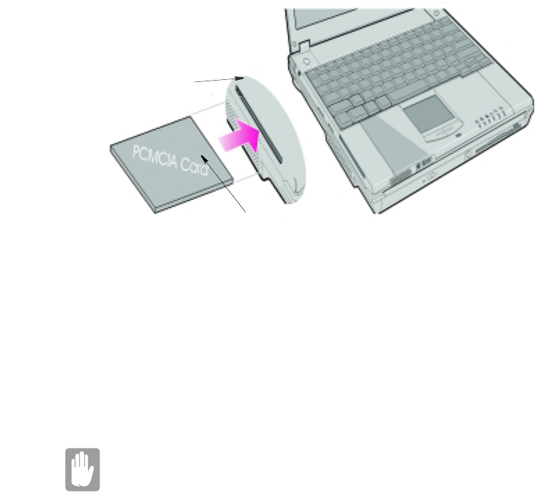
To insert a PC Card into a slot:
1. Push the slot door in with the PC Card.
Working with PCMCIA (PC) Cards 105
2. Align the card with a slot and insert the card into the slot until it locks in place. See
“Inserting a PC Card” on page 105.
The eject button for the card slot operates in two steps, therefore to remove a PC Card:
1. Push the eject button once to pop it outward.
2. Push the eject button again, then the card will be ejected.
Figure 45. Inserting a PC Card
Windows 98/Me
Windows 98/ Me automatically assigns computer resources (such as communication
ports and memory addresses) to a PC Card installed in your computer. For further
information on configuring a PC Card in Windows 98/ Me, see the index entry PC card
in the Windows Help. Windows 98/ Me also handles power management for PC Cards.
To remove a PC Card from your computer if your operating system is Windows 98/
Me:
Use the following procedures to remove PC Cards, or you may lose data
that is being stored to a card.
1. Click the PC Card icon on the taskbar.
2. Select the name of the card you want to remove, and then click the Stop button.
3. Push the card eject button on the side of the PC Card slot when prompted to do so.
Eject button
PC Card
Insert PC card with product
information facing up
106 Working with PCMCIA (PC) Cards
4. Pull the card out of the PC Card slot.

Using Options 107
Using Options
You can order the following options for your Notebook computer from your authorized
reseller:
•An extra AC adapter.
•An extra battery pack. [Standard or large size]
•An upgraded hard drive. Optional hard drives are available to fit in the hard drive
compartment or the Multi-Bay docking station. [IBM HDD is currently supported]
•64,128 and 256 MB SDRAM memory modules that enable you to upgrade your
computer’s memory to a maximum of 320MB.
•A CD-ROM drive module. [5.25" Multi-bay]
•A DVD-ROM drive module. [5.25" Multi-bay]
•A CD-RW drive module. [5.25" Multi-bay]
•A Zip 250 Mb drive. [3.5" Multi-bay]
•Docking options that enable you to use your computer like a desktop computer.
The options that are available may change periodically. Contact your reseller for
updated information on current and new options.
Battery Pack
You can order another smart lithium-ion battery pack for your computer. See ”Using
the Battery” on page 45 for information on the battery.
Hard Drives
You can order optional hard drives for your system. A hard drive can be installed in the
3.5" compartment of the Multi-bay docking station. See ”Using the Multi-Bay Docking
Station” on page 30 for information on installing a device in the Multi-Bay docking
station.

108 Using Options
Memory Modules
You can increase system memory by installing optional memory modules. You can
install a 32, 64 or 128 MB modules.
To avoid possible system problems, use only approved memory
modules in your computer.
Before You Install Memory
To prevent personal injury and damage to the equipment, follow the
precautions listed here before installing a memory module.
Take the following precautions when installing a memory module:
•Before you remove the memory module compartment door, turn off the computer,
unplug the power cord, and remove the battery. Also, disconnect any peripheral
devices.
•Before handling a memory module, discharge any static electricity by touching a
grounded surface or using a grounding wrist strap.
•Do not insert objects with conductive material, such as metal screwdrivers or
graphite pencils, into the memory-module compartment.
•Be careful in handling the metal plate of the memory door.
Installing a Memory Module
Handle a memory module carefully. Hold them only by the edges.
To install a memory module:
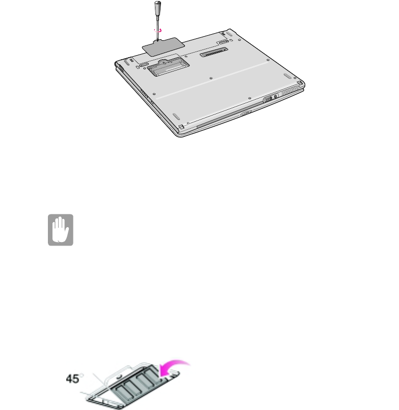
1. Turn the computer over so that the bottom faces up.
2. Using a screwdriver, remove the screw that holds the memory-module
compartment door in place (Figure 48).
Using Options 109
Figure 46. Removing the Memory Module Compartment Door
3. Grasp the edge of the door and pull the door off the chassis.
4. Remove installed modules if necessary:
When removing modules, pull on the plastic portion of the connector
slots tabs only. Do not pull on the metal part of the tabs, or you may
damage the tabs.
a. Pull the tabs on the connector slot outward slightly, until the edge of the memory
module pops up.
b. Hold the memory module by the edges and pull it forward out of the
compartment.
5. Align the connector on the memory module with the connector of the slot.
6. Push the memory module intothe slot at a slight angle until the connectors are fully
engaged (Figure 49).
Figure 47. Installing a Memory Module
7. Push down on the edge of the memory module until the module snaps into place.
8. Align the memory module compartment door with the compartment and push the
door down until it snaps into place.

110 Using Options
9. Reinstallthescrewyouremovedinstep2.
10.Turn on the computer and perform a complete POST to check the memory
integrity.
CD-ROM Drive
If your system did not ship with a CD-ROM drive included, you can order a drive. See
”Using the CD/DVD-ROM Drive” on page 33 for directions on installing the CD-
ROM drive.
DVD-ROM Drive Module
If your system did not ship with a DVD-ROM drive included, you can order a drive.
The DVD-ROM drive module can be inserted into your computer exactly as you would
insert a CD-ROM. See ”Using the CD/DVD-ROM Drive” on page 33 for directions
on installing and using the CD-ROM drive. There is MPEG-2 software included with
the drive that will enable you to play DVD movies from the DVD-ROM drive.
Docking Options
Contact your reseller for a list of docking options available for your Notebook
computer. User’s manuals are included with the docking options. See ”Using the
Multi-Bay Docking Station” on page 30 for a list of options available.

Troubleshooting 111
Troubleshooting
If you ever have difficulty running your computer, follow these steps:
1. Consult the following sections for advice on how to handle system problems.
2. If steps 1 do not help you to resolve the problem, contact your reseller.
Operating Problems
This section tells you what to do if you have problems running your computer. If any
problem persists after you take corrective action, contact your reseller for assistance.
The computer does nothing when you turn it on.
Has the battery run down? Connect the power cord to get power and recharge the
battery. Try turning on the computer again.
Nothing appears on the LCD panel when you turn on the computer.
Adjust the brightness on a TFT LCD. Are you using an external monitor? If so,
press <Fn+F5> to return to the LCD panel.
Nothing appears on the external monitor when you switch the display to it.
Is the monitor properly connected to the computer? Is the monitor’s power cord
connected to an AC wall outlet? Check the brightness and contrast controls on the
monitor. Does the program appear on the LCD panel instead of the external
monitor? If so, press <Fn+F5> to switch to the monitor. Try turning the monitor
off and on again.
The external monitor displays flashes or waves.
Check the cables between the monitor and the computer. Are they properly
installed?
Some of the letter keys type numbers instead of the indicated letters.
Is the Num Lock light on? If so, the numeric keypad on the keyboard is active. To
return the keypad keys to typing letters, press <Num Lock>.
Battery power seems to run out faster than expected.
If you are running the computer from the battery rather than the power cord, make
sure that you set the Idle Mode field in System Setup to On. This setting enables

112 Troubleshooting
the microprocessor and the hard drive to slow down when the computer is not
busy.
Certain software programs “hang” during operations when there is no
interaction with the keyboard or peripheral devices.
Your computer may be in Suspend or Rest mode. Tap the touchpad to resume
from Suspend or press the power button to resume from rest.
A PC Card does not work correctly.
Make sure that the PC Card is inserted left side up in the PC Card slot. Check that
the card is inserted fully into the slot. If you are using a PC Card modem, check
the modem cable connections. For the Windows 98 operating system, try setting
the Installed OS fieldinSystemSetuptoYes to enable Windows 98 to autosense
an older PC Card.
The System Setup settings are not retained when you turn off the computer.
The CMOS battery inside the computer may need to be replaced. The CMOS
battery provides power to save the system BIOS information when the computer
is turned off. Normally, the CMOS battery lasts for several years. Do not attempt
to open the chassisand replace this battery yourselfor your warranty is void. Have
an authorized the manufacturer’s service center replace the CMOS battery.
Infrared Problems
If your computer’s operating system is Windows 98/ Me, you can enable and use the
infrared port.
If you are unable to transfer files with the infrared port, check the following:
•Make sure the Infrared port field in System Setup is set to 2F8, IRQ 3.Thefieldis
in the I/O Device Configuration under Advanced Menu.
•The receiving device must be positioned properly. There must be no more than
three feet of distance between the computer’s infrared port and the receiving
infrared device.
•The sending and receiving devices need to be on the same level vertically. Place
themonthesametableifpossible.
•Make sure the infrared ports on the sending and receiving devices face each other,
with no more than a 30 degree angle between the two infrared ports.
•Make sure that nothing is obstructing the file transfer path between the computer’s
infrared port and the receiving infrared device.

Troubleshooting 113
If you still cannot transfer a file, see the online help.
Modem Problems
My modem doesn't connect to services or disconnects during communication
If your modem has difficulty in connecting to on-line services and sustaining
communications, firstly check the quality of the phone line. Interference from
certain devices or poor line power conditions may degrade the quality of your
connection. Under these conditions gradually reduce the communication speed of
your modem until a reliable connection is achieved.
Check your on-line service provider. Service line or service may be halted.
When using a PBX phone system I can't dial on my modem.
If you use a PBX phone system you may need to press a number i.e. '9' to connect
to an external line, you should enter the following command before trying the
connection and check modem initialization.
ATX3&W
And add "9," as the external line prefix (in our example) of the phone number
when using the dial command "ATDT9, 123-4567".
Screen displays random or garbage characters during communications.
After your modem has connected to the on-line service, your screen may display
garbage characters or after-images in screen transitions. This problem is caused
by a mismatch of the terminal modes between communications service and
communications programs. You need to match the terminal modes to each other.
Refer the user's guide of the communications program you're using.
Reports error message that insufficient Hard Disk space is available.
Delete the unnecessary messages or data you received by Modem or Fax every
one to three months as required.
If you're using WWW of the internet, many picture and data files can get
downloaded to your HARD DISK every time you visit a home page, which will
consume a lot of your HARD DISK space. Delete the unnecessary messages or
data you received by Modem or Fax every one to three months as required. For
more detailed information about the method of deleting, refer to the help of the
Web browser you've been using or your user's guide.

114 Troubleshooting
Depending on telephone line status, or types of Fax machines/programs
that send/receive the Fax, Fax transmission/reception may not work
correctly. In that case, please try other Fax programs. (e.g. Microsoft
Fax)

Specifications 115
Specifications
Table 9 gives the specifications for computers.
Table 8. Hardware Specifications
Dimension
* LCD viewing area
LCD viewing area (12.1 TFT) 26.7 x 18.6 cm
Width [Docking Station] <Notebook> [27.4 cm] <27.3 cm>
Depth [Docking Station] <Notebook> [23.0 cm] <22.7 cm>
Height [Docking Station] <Notebook> [25.0 cm] <19.8 - 22.3 cm>
Weight (with integrated floppy drive,
Li-Ion battery & 14.1” TFT LCD & weight
saver)
~3200 g
Environment
Ambient temperature, operating 50o–90oF(10
o–32oC)
Ambient temperature, storage 23o–104oF(-5
o–40oC)
Relative humidity (noncondensing),
operating
20–80%
Relative humidity (noncondensing), storage 5–90%
Altitude, operating 0 to 8,000 ft (0 to 2,348 m)
Altitude, storage 0to40,000ft(0to12,192m)
Shock, operating 10 G for 11 ms half sine
Shock, nonoperating 60 G for 11 ms half sine
Lithium-Ion Smart Battery [Large]
Normal Weight 0.99lb (450g)
Nominal open circuit voltage 7.4 VDC
Capacity, typical 53 whr
Charging time, approximate, with computer
turned off, typical
~3.0 hr
Charging time, approximate, with computer
turned on, typical
~5.0 hr

116 Specifications
Average battery life, with no power
management enabled
~5 hr
Lithium-Ion Smart Battery [Small]
Normal Weight 0.99lb (450g)
Nominal open circuit voltage 7.4 VDC
Capacity, typical 24 whr
Charging time, approximate, with computer
turned off, typical
~3.0 hr
Charging time, approximate, with computer
turned on, typical
~5.0 hr
Average battery life, with no power
management enabled
~2.5 hr
External AC Adapter
Operating voltage 100-240 VAC
Line frequency 50-60 Hz
Input current 1.2 A 100 V ~ 0.6 A 240 V
Output current 3.2 A
Output voltage 12.0 VDC

Abbreviations 117
Abbreviations
Your computer’s documentation uses the following abbreviations:
A......... Amperes
AC . . . . . . . . Alternating current
ACPI . . . . . . Advanced Configuration and Power management Interface
APM . . . . . . Advanced Power Management
ATA. . . . . . . AT attachment (refers to the hard-drive interface in an AT-
compatible computer)
ATAPI. . . . . AT attachment packet interface
BBS ....... Bulletinboardsystem
BIOS . . . . . . Basic input/output system
C......... Centigrade
CD ........Compactdisc
CD-ROM . . Compact disc read-only memory
cm ........ Centimeters
COM . . . . . . Communication (as in communication port)
CMOS . . . . . Complementary metal-oxide semiconductor
DC . . . . . . . . Direct current
DMA ......Directmemoryaccess
DPMS . . . . . Display power-management signaling
DRAM. . . . . Dynamic random access memory
DSTN . . . . . Double layer super twist nematic
ECP . . . . . . . Extended capabilities port
EPP . . . . . . . Enhanced parallel port
F.......... Fahrenheit
FIR . . . . . . . Fast infrared
ft. ......... Feet
g.......... gram
G......... Gravity
GB . . . . . . . . Gigabytes
hr ......... hour
118 Abbreviations
Hz ........ Hertz
IDE . . . . . . . Integrated drive electronics
in ......... Inches
I/O . . . . . . . . Input/output
IrDA . . . . . . Infrared Data Association
IRQ . . . . . . . Interrupt request line
ISA . . . . . . . Industry Standard Architecture
KB ........Kilobytes
kg......... Kilograms
LAN. . . . . . . Local-area network
lb.......... Pounds
LBA . . . . . . . Logical block addressing
LCD. . . . . . . Liquid-crystal display
m......... Meters
mA........Milliampere
mAhr ......Milliamperehour
MB. . . . . . . . Megabyte
mm . . . . . . . millimeter
MPEG . . . . . Motion Picture Experts Group
MPU . . . . . . Microprocessor unit
ms ........ Millisecond
PDF . . . . . . . Portable document format
PC . . . . . . . . Personal computer
PCI . . . . . . . Peripheral component interconnect
PCMCIA. . . Personal Computer Memory Card International Association
POST. . . . . . Power-on self-test
PNP .......Plugandplay
PS/2 .......PersonalSystem/2
RAM ......Random-accessmemory
ROM . . . . . . Read-only memory
SVGA . . . . . Super video graphics array
S-VHS . . . . . Super VHS
TFT . . . . . . . Thin-film transistor
Abbreviations 119
USB . . . . . . . Universal serial bus
V......... Volt
VAC . . . . . . Voltage alternating current
VCC . . . . . . Voltage collector current
VDC . . . . . . Voltage direct current
whr ....... Watthour

120 Glossary
Glossary
AC adapter
The AC (or alternating current) adapter regulates current coming into your
computer from the wall outlet. The current at the wall outlet is alternating current
and needs to be changed by the adapter to DC (direct current) before your
computer can use it for power.
ACPI
ACPI (Advanced Configuration and Power Interface)- a method for describing
hardware interfaces in terms abstract enough to allow flexible and innovative
hardware implementations and concrete enough to allow shrink-wrap OS code to
use such hardware interfaces.
BIOS
BIOS stands for basic input/output system. The BIOS is software (often called
firmware) that is independent of any operating system. It enables the computer to
communicate with the screen, keyboard, and other peripheral devices without
using programs on the hard disk.
The BIOS on your computer is flash BIOS, which means that it has been recorded
on a flash memory chip that can be updated if needed.
Boot
To start your computer. A cold boot resets the entire computer and runs through
all computer self-tests. A warm boot clears out computer memory only.
Boot disk
A disk containing operating system programs required to start your computer. A
boot disk can be a floppy disk, hard drive, or compact disc.
Byte
The basic unit of measure for computer memory. A character—such as a letter of
the alphabet—uses one byte of memory. Computer memory is often measured in
kilobytes (1,024 bytes) or megabytes (1,048,576 bytes).
Each byte is made up of eight bits. For more information on bytes and bits, see an
introductory book on computers.
Glossary 121
Cache memory
Cache is very fast, zero-wait-state memory located between the microprocessor
and main memory. Cache reduces the average time required by the
microprocessor to get the data it needs from the main memory by storing recently
accessed data in the cache.
CardBus
CardBus technology enables the computer to use 32-bit PC Cards. Hardware in
the computer and the Windows 98 operating system provide support for the 32-
bit cards. The voltage of 32-bit cards (3.3 volts) is lower than that of 16-bit cards
(5 volts). The 32-bit cards can transmit more data at a time than the 16-bit cards,
thus increasing their speed.
CMOS memory
CMOS (complementary metal oxide semiconductor) memory is powered by the
CMOS battery. The System Setup settings and other parameters are maintained in
CMOS memory. Even when you turn your computer off, the information in
CMOS memory is saved.
COM port
COM stands for communication. COM ports are the serial ports in your computer.
Compact Disc
A compact disc (CD).
Conventional memory
The first 640 KB of system memory. Operating systems and application programs
can directly access this memory without using memory-management software.
Disk
The device used by the computer to store and retrieve information. Disk can refer
to a floppy disk, hard disk, or RAM disk.
Disk cache
A software device that accumulates copies of recently used disk sectors in RAM.
The application program can then read these copies without accessing the disk.
This, in turn, speeds up the performance of the application.
A cache is a buffer for transferring disk sectors in and out of RAM. Data stored in
a disk cache is a copy of data already stored on the physical disk.
122 Glossary
DMA (direct memory access)
A method of transferring data from a device to memory without having the data
pass through the microprocessor. Using DMA can speed up system performance.
DPMS
Display Power Management Signalling. Displays or monitors that comply with
this can be managed by the Power Management features found in the system
setup.
Floppy disk
A removable disk, also called floppy or diskette.
Hard drive
Also called fixed disk. A hard drive is connected to the computer and can be
installed or removed. Data written to a hard drive remains until it is overwritten
or corrupted.
The 2.5-inch hard drive in your computer was designed for use in a notebook
computer. Because hard drives in notebook computers are smaller than those in
desktop computers, their maximum storage capacity may be less than that of
desktop hard drives. However, because of their smaller size, the drives handle
shock and vibration better than larger drives, which is important for a notebook
computer.
I/O
Input/output. Refers to peripheral devices, such as printers, that are addressed
throughanI/Oaddress.
I/O address
I/O stands for input/output. Peripheral devices, such as printers, are addressed
through the I/O port address.
IRQ (interrupt request line)
The IRQ is a hardware line that a device uses to signal the microprocessor when
the device needs the microprocessor’s services. The number of IRQs is limited by
industry standards.
LCD (liquid-crystal display)
The LCD screen on your computer differs from the display screen of a desktop
monitor. Most desktop monitors use CRT (cathode-ray tube) displays, which
work by moving an electron beam across phosphor dots on the back of the screen.
The phosphor dots light up to show the image. LCDs use a liquid-crystal solution
between two sheets of polarizing material. Electric current passing through the
Glossary 123
liquid aligns the crystals so that light can or cannot pass through them, creating an
image.
MB (megabyte)
1,024 kilobytes.
Megabit
1,048,576 bits or about 128 kilobytes.
Operating system
A program that supervises the computer's operation, including handling I/O.
Application programs and users can request operating-system services. A user
might request operation-system services to copy files or format a disk. An
application program might use the operating system to obtain keyboard input,
write data to a file, or write data to a screen.
PC Card
PC Card stands for personal computer card. The Personal Computer Memory
Card International Association (PCMCIA) defines the standards used to develop
all PC Cards. PC Card types include: modems, Ethernet adapters, SCSI adapters,
ATA cards, and memory cards.
PC slot
The PC slot is the hardware slot in the computer where the PC Card is placed.
Pixel
A pixel is an individual dot in a graphic displayed on your computer. The pixels
are so close together that they look as though they are connected. An LCD screen
displays thousands or millions of pixels.
Plug and Play
A plug and play operating system automatically configures computer components
to work with your system. With this type of operating system, you normally do
not need to set jumpers on devices or set memory addresses or IRQs.
POST
POST stands for power-on self-test. POST is a test performed by the computer
whenever you turn on the power. POST checks system integrity.
RAM (random access memory)
The computer's system memory, including conventional and extended memory.
You can write to and read from RAM. Information stored in RAM is temporary,
andiserasedwhenthesystemisturnedoff.
124 Glossary
Refresh rate
The refresh rate is the rate at which the image on the LCD screen is rewritten to
the screen. A fast refresh rate helps keep the image from flickering.
Resolution
The resolution is the sharpness or clarity of the image on your LCD screen.
Resolution is measured by the number of pixels the computer’s screen can
display. For example, a resolution of 800x600 means that the screen can display
800 pixels in row and can display 600 rows. The more pixels displayed, the higher
the resolution and the better the image.
ROM (read-only memory)
Permanent computer memory dedicated to a particular function. For example, the
instructions for starting the computer when you first turn on power are contained
in ROM. You cannot write to ROM. (ROM is not the same as RAM).
Sector
Also known as disk sector. The portion of a track that is numbered and can hold
a specified number of characters (usually 512 KB).
Shadow RAM
A write-protected area of RAM that contains a copy of the BIOS. As the computer
boots, the BIOS is copied from its permanent location in ROM to RAM. The
BIOS can be executed much faster in RAM than in ROM. The BIOS remains in
shadow RAM until you turn off the computer.
TFT (thin film transistor) LCD
A TFT LCD uses a separate transistor circuit to control each pixel. This
technology provides the best resolution for an LCD screen. A TFT LCD is also
sometimes called an active matrix LCD.
Zoomed video
Zoomed video technology enables zoom video PC Card to transfer data directly
from the card to video and audio systems without going through the
microprocessor. This process improves video performance. Video conferencing
and real-time multimedia devices, such as video cameras, are supported by zoom
video.

Computer Hardware Configuration 125
Computer Hardware Configuration
In the spaces provided, write the System Setup program settings. If your computer ever
loses configuration information, you can enter the information from this section into
System Setup to restore it.
MAIN MENU
Legacy Diskette A: 1.44/1.25 MB 3 1/2“ Disabled
IDE ADAPTER SUBMENU
Primary Master:
Type:__________
Multi-Sector Transfers:_____
LBA Mode Control: Enabled Disabled
32 Bit I/O: Enabled Disabled
Transfer Mode: Standard Fast PIO 1
Fast PIO 2 Fast PIO 3
Fast PIO 4
Ultra DMA Transfer Mode: Mode 0 Mode 1
Mode 2 Disabled
Secondary Master:
Type:___________
Multi-Sector Transfers:_________
LBA Mode Control: Enabled Disabled
32 Bit I/O: Enabled Disabled
Transfer Mode: Standard Fast PIO 1
Fast PIO 2 Fast PIO 3
Fast PIO 4
Ultra DMA Transfer Mode: Mode 0 Mode 1
Mode 2 Disabled
ADVANCED MENU

126 Computer Hardware Configuration
Installed O/S: Other Win95/Win98APM
Win98ACPI/Win2000
PS/2 Mouse: Disabled Single Mouse
Dual Mouse
Screen Expansion: Enabled Disabled
TV Out Mode: NTSC PAL
Display Configuration: LCD CRT Both
I/O DEVICE CONFIGURATION SUBMENU
Serial port: Enabled Auto Disabled
Base I/O Address 3F8, IRQ 4 2F8, IRQ 3
3E8, IRQ 4 2E8, IRQ 3
Infrared port: Enabled Auto Disabled
Base I/O Address 3F8, IRQ 4 2F8, IRQ 3
3E8, IRQ 4 2E8, IRQ 3
Mode FIR
DMA Channel DMA 3 DMA 1
Parallel port: Enabled Auto Disabled
Mode Output only Bi-directional
EPP ECP
Base I/O Address 378, IRQ 378, IRQ 5 278, IRQ 7
278, IRQ 5 3BC, IRQ 7 3BC, IRQ 5
DMA Channel DMA 1 DMA 3
Floppy disk controller: Enabled Auto Disabled
Local Bus IDE adapter: Both Disabled
Primary Secondary
Large Disk Access Mode: DOS Other
SECURITY MENU

Computer Hardware Configuration 127
Set password ___________
Password on boot: Enabled Disabled
Fixed disk boot sector: Normal Write Protect
POWER MENU
Intel (R) Speedstep (TM) Performance Battery
Automatic Disabled
Idle Mode: Off On
Suspend Mode: Save to RAM Save To Disk
Suspend Time-out: Off Time_________________
Resume On Modem Ring: On Off
Resume On Time: On Off
Resume Time:________________________
BOOT MENU
Logo Screen: Enabled Disabled
Summary screen: Enabled Disabled
Boot Device Priority:
Boot option 1:________________________
Boot option 2:________________________
Boot option 3:________________________
Boot option 4:________________________