Samsung Electronics Co SLS-BU102 eSmallCell (enterprise SmallCell) User Manual
Samsung Electronics Co Ltd eSmallCell (enterprise SmallCell)
UserManual.wiki
>
Samsung Electronics Co
>
SLS BU102 User Manual
User Manual
Navigation menu
Upload a User Manual
Namespaces
Wiki Guide
HTML
PDF
Info
Views
User Manual
Discussion / Help
Navigation
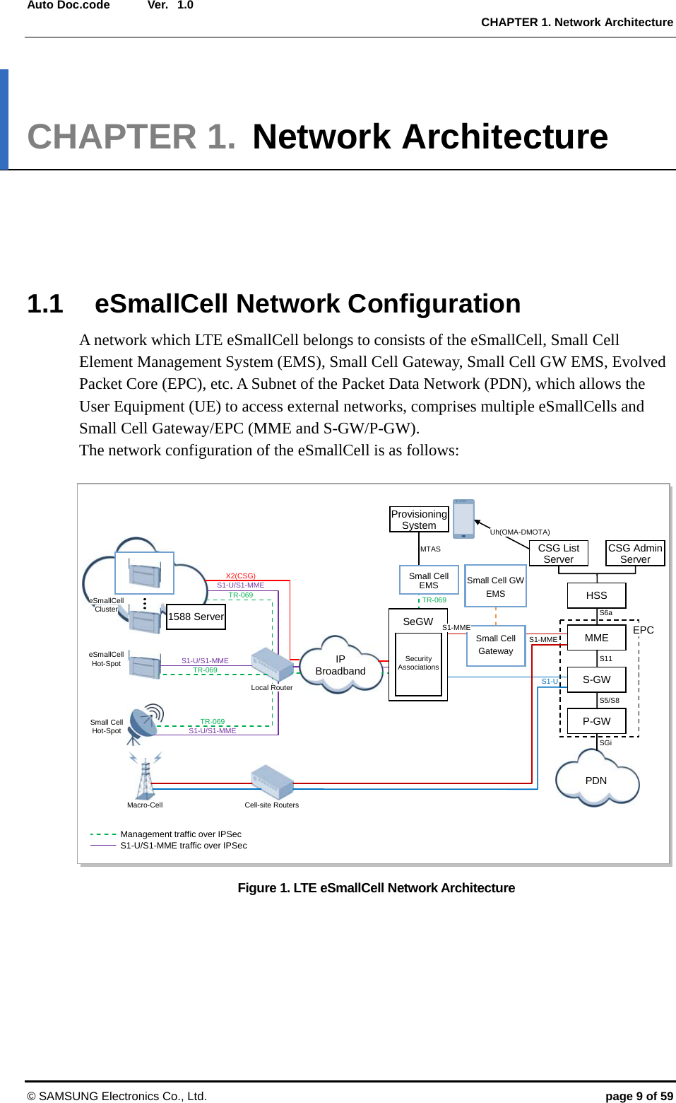
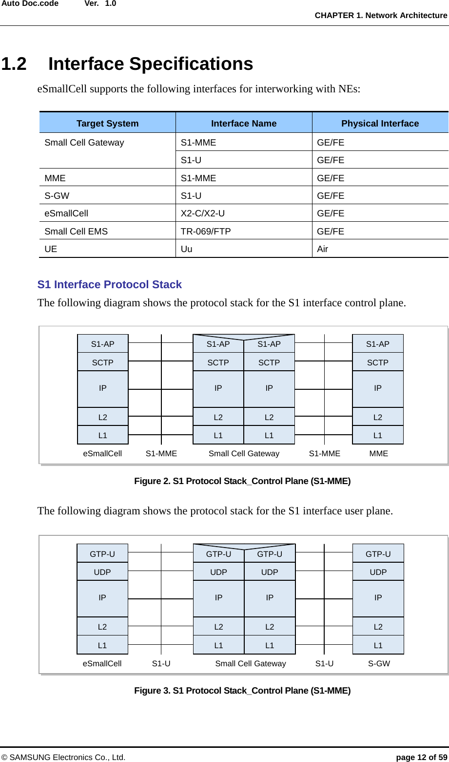
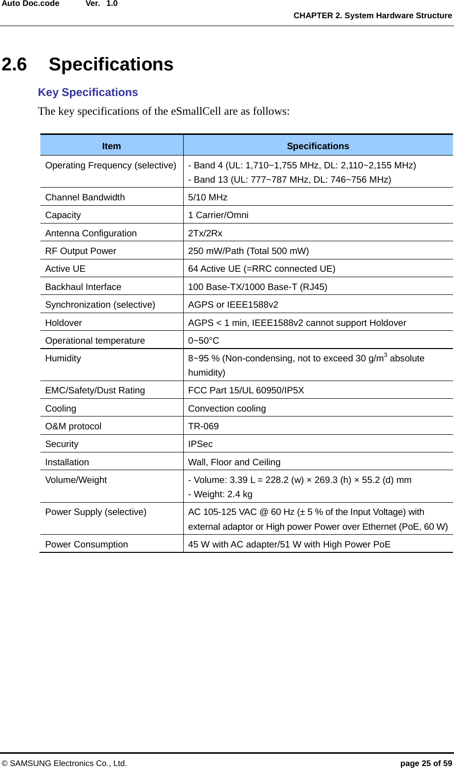
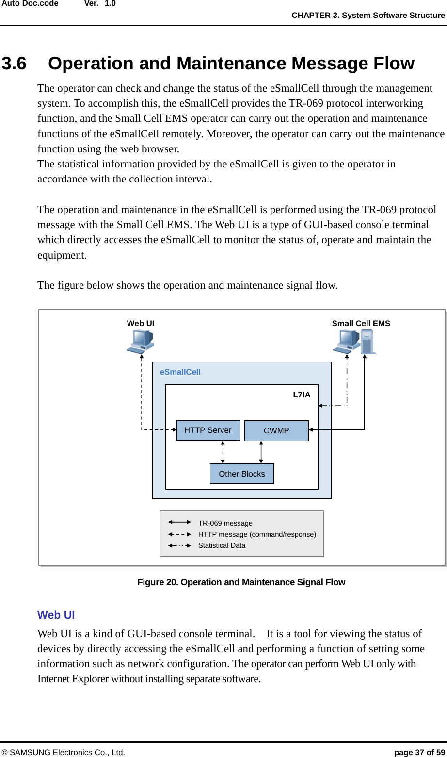
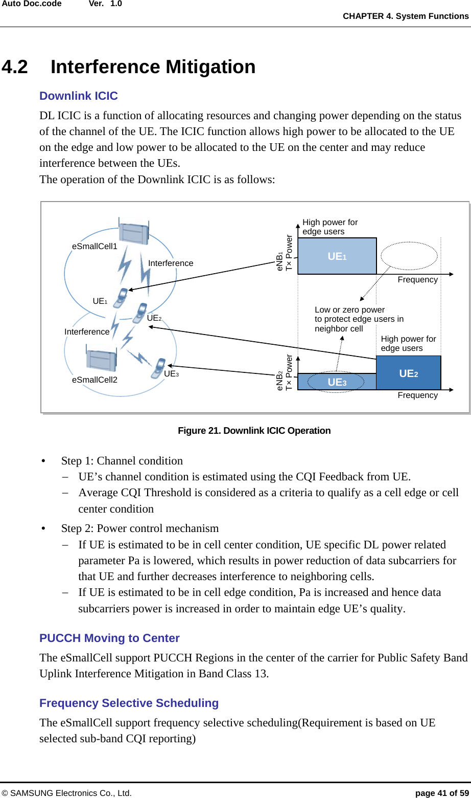
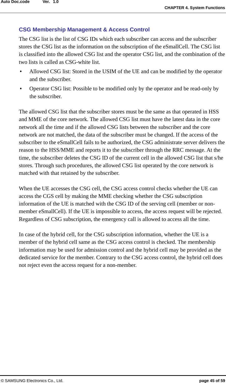
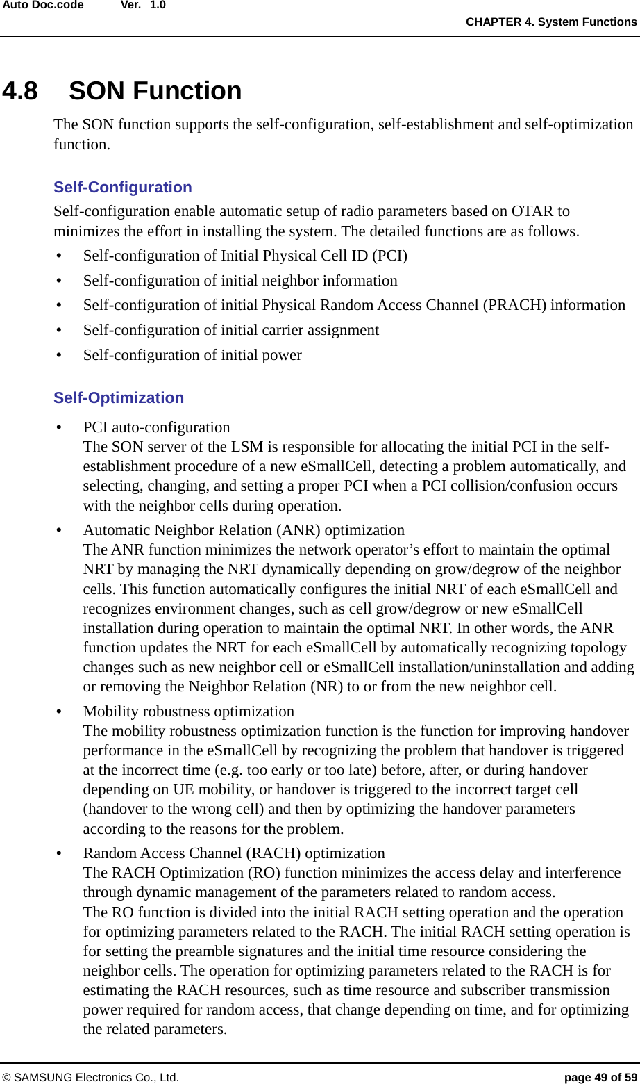
![Ver. CHAPTER 1. Network Architecture © SAMSUNG Electronics Co., Ltd. page 13 of 59 Auto Doc.code 1.0 Uu Interface Protocol Stack The following diagram shows the protocol stack for the Uu interface. Figure 4. Uu Protocol Stack X2 Interface Protocol Stack The following diagram shows the protocol stack for the X2 interface between eSmallCells. Figure 5. X2 Protocol Stack Uu UE PDCP RLC MAC PHY eSmallCell PDCP RLC MAC PHY UE PDCP RLC MAC PHY eSmallCell RRC PDCP RLC MAC PHY RRC Uu [User Plane] [Control Plane] eSmallCell IP L2 L1 eSmallCell IP L2 L1 SCTP SCTP eSmallCell UDP IP L2 L1 eSmallCell UDP IP L2 L1 GTP-U GTP-U [User Plane] [Control Plane] User Plane PDUsUser Plane PDUs X2-AP X2-AP X2-C X2-U](https://usermanual.wiki/Samsung-Electronics-Co/SLS-BU102/User-Guide-2116973-Page-13.png)
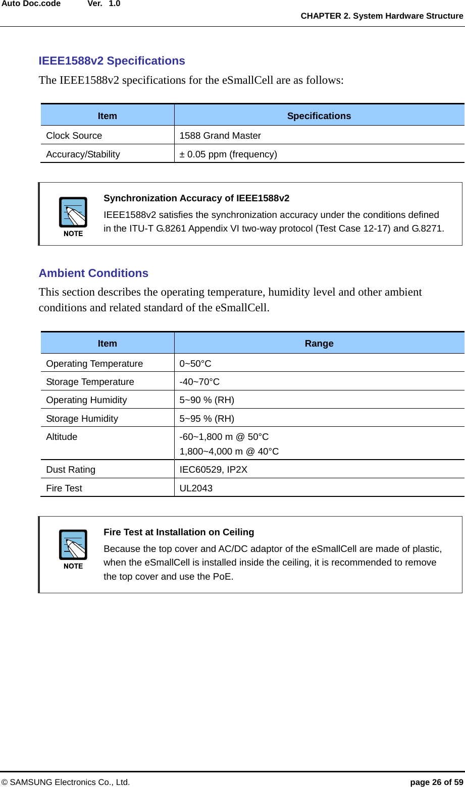
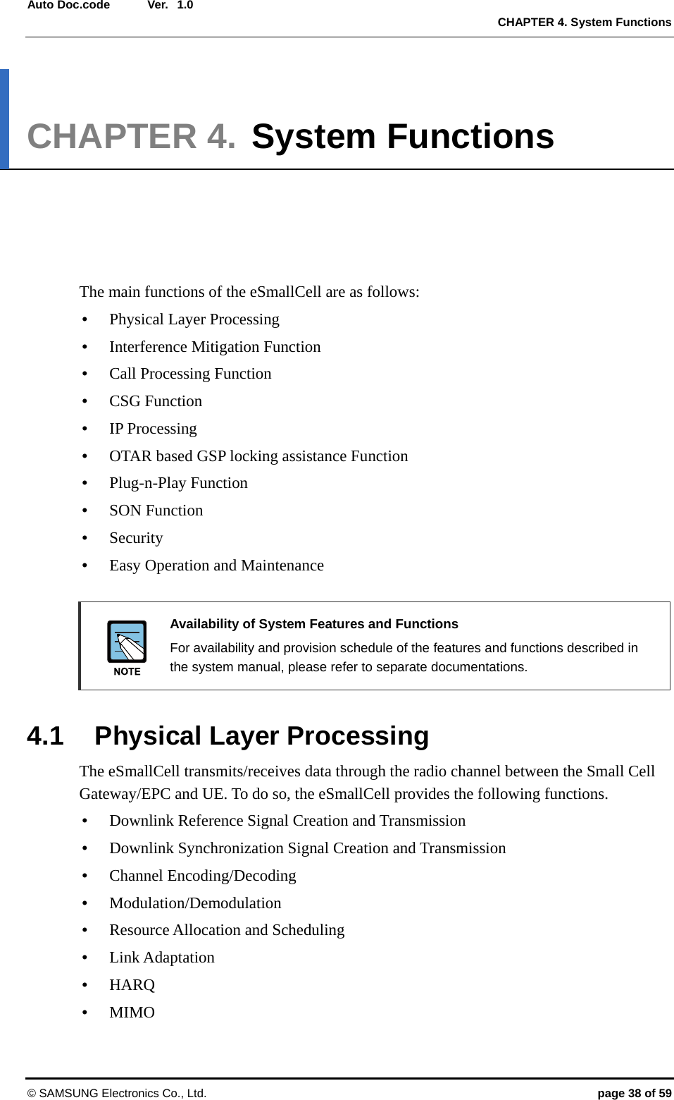
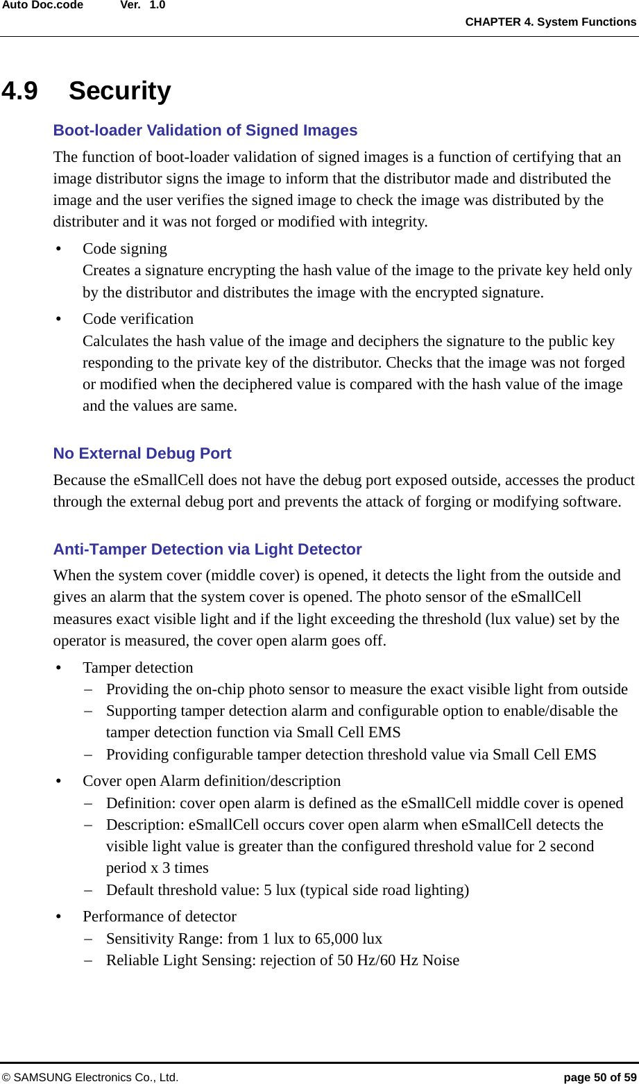
![Ver. CHAPTER 2. System Hardware Structure © SAMSUNG Electronics Co., Ltd. page 24 of 59 Auto Doc.code 1.02.5 Mount Bracket The following figure shows a bracket required when the eSmallCell is mounted on the floor, wall or ceiling. Figure 13. Mount Bracket Configuration The eSmallCell may be installed in the following shape by mounting the mount bracket: Figure 14. eSmallCell Installation (Example) [Floor, Wall and Ceiling-Side Bracket] [eSmallCell-Side Bracket] [Floor] [Wall] [Ceiling]](https://usermanual.wiki/Samsung-Electronics-Co/SLS-BU102/User-Guide-2116973-Page-24.png)