Samsung Electronics Co SWDY3100 Cellular/PCS GSM/EDGE/WCDMA Mini PCI Transmitter Card User Manual
Samsung Electronics Co Ltd Cellular/PCS GSM/EDGE/WCDMA Mini PCI Transmitter Card Users Manual
Contents
- 1. Users Manual
- 2. Manual
- 3. User Manual 1
- 4. User Manual 2
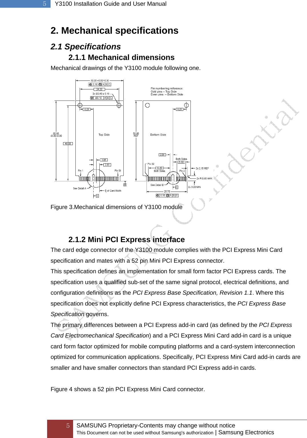
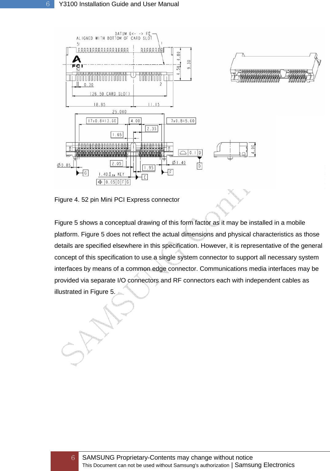
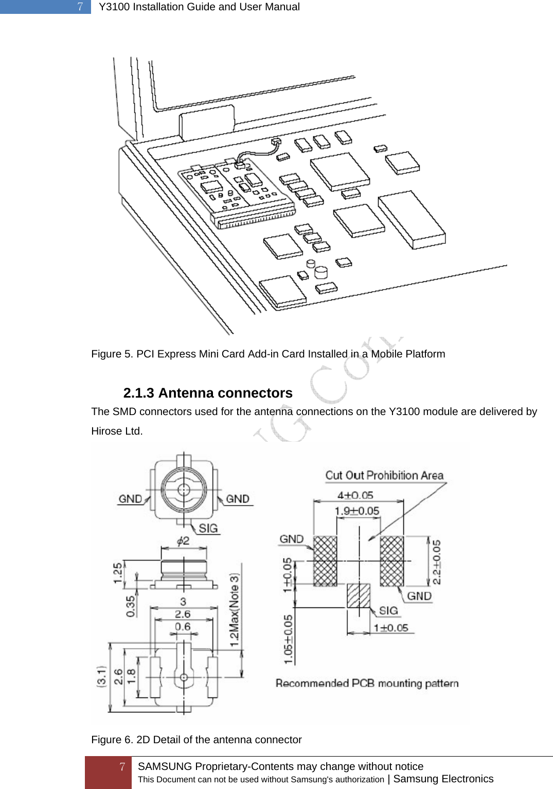
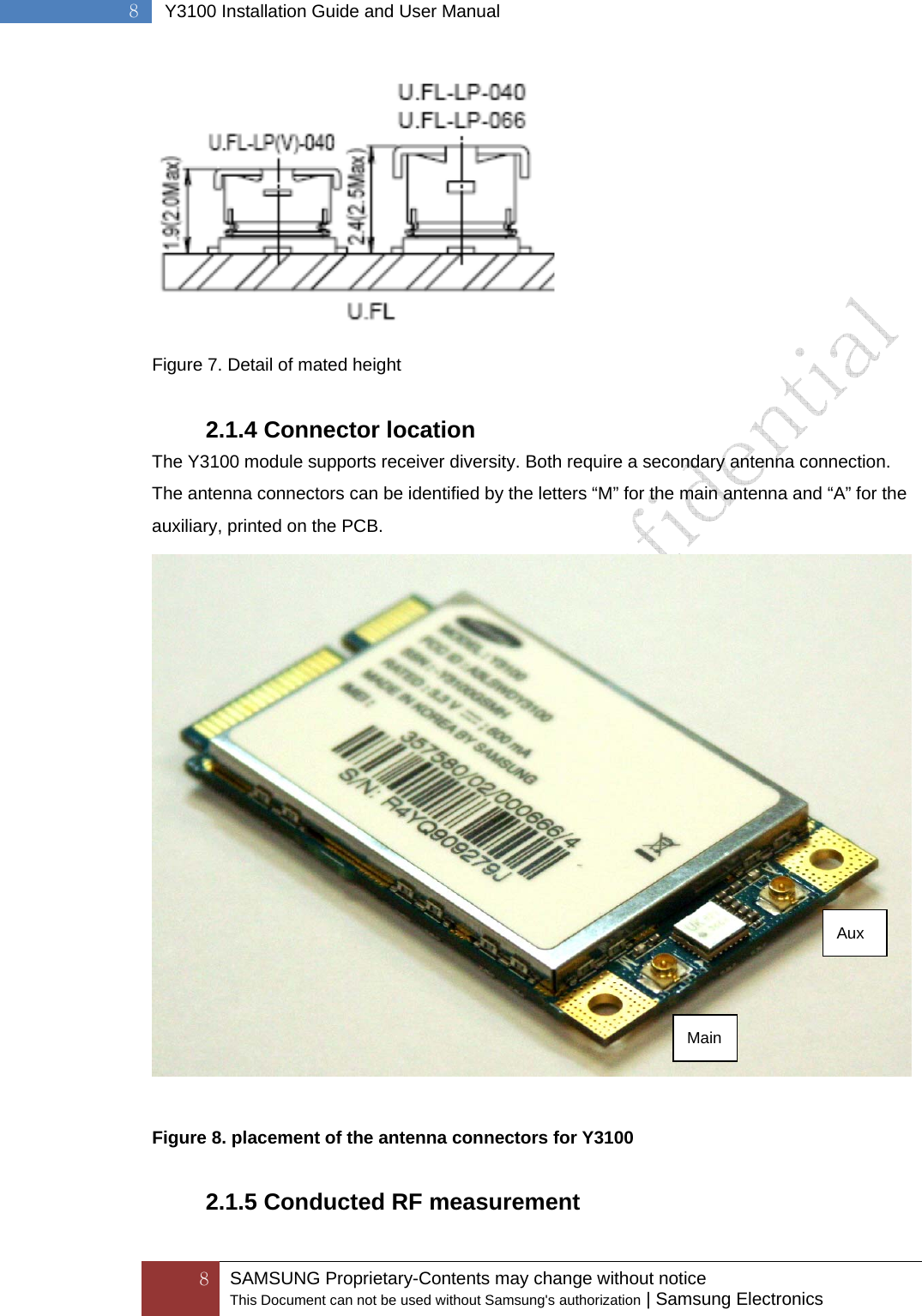
Users Manual