Sandia Aerospace DAGEDX AVIATION TRANSPONDER User Manual STX360 032417 5ER
Sandia Aerospace Corporation AVIATION TRANSPONDER STX360 032417 5ER
UserManual.wiki
>
Sandia Aerospace
>
DAGEDX User Manual
User Manual
Navigation menu
Upload a User Manual
Namespaces
Wiki Guide
HTML
PDF
Info
Views
User Manual
Discussion / Help
Navigation
![__________________________________________________________________1.4 ScopeThis installation manual covers equipment for the STC and is shown in Table 1. All equipment interfaced with the STX 360 must be installed in accordance with the manufacturers data. Equipment interfacing with the STX 360 in this manual are determined to be compatible.1.5 STX 360 / STX 360R Product DescriponThe STX 360 is a self-contained, tray mounted ADSB dual mode radio that utilizes a Mode C transponder and UAT IN and OUT. The SANDIA STX 360 accepts position data from WAAS GPS position source such as the FREEFLIGHT WAAS/GPS 1201, the GARMIN 430W, 530W. SANDIA STX 360 will accept a WAAS position source that has RS 232 or RS 422 interface.SANDIA STX 360 accepts altitude data from altitude encoders:•Air-Data (RS-232)◦Icarus Format◦Garmin G Format ▪SANDIA SAE 5-35 [Blind Encoder]▪SANDIA SAC 7-35 [Air Data Computer]▪SANDIA SAI 340 [Altitude Indicator]•Air-Data (ARINC-429)The STX 360R is a remote version that is also a self-contained ADSB dual mode radio that utilizes a MODE C transponder and UAT IN and OUT. The SANDIA STX 360R accepts attitude data from altitude encoders, such as the SANDIA SAE5-35, in either Gilham Grey code or RS 232 format. The SANDIA STX 360R accepts position data from WAAS GPS position source such as the FREEEFLIGHT WAAS/GPS 1201, the GARMIN 430 W and 530W. SANDIA STX 360 will accept a WAAS position source that has RS 232 or RS 422 interface.Both units reply to ATCRBS interrogations with one of 4096 possible ‘squawk’ codes and an “anonymous mode” when flying in VFR mode when enabled.www.sandia.aero 306467-00 STX 360 Installaon Manual REV 1Page 12Table 1: Equipment under STCEquipment covered by STC Equipment not covered by STCSANDIA STX 360 Transponder/ UAT AntennaSANDIA STX 360R GPS AntennaWAAS GPS posion sources as shown in Table 6Altude Encoders as shown in Table 7Installaon kit, mechanical and Electrical – secon 3.2.1.1](https://usermanual.wiki/Sandia-Aerospace/DAGEDX/User-Guide-3334488-Page-12.png)
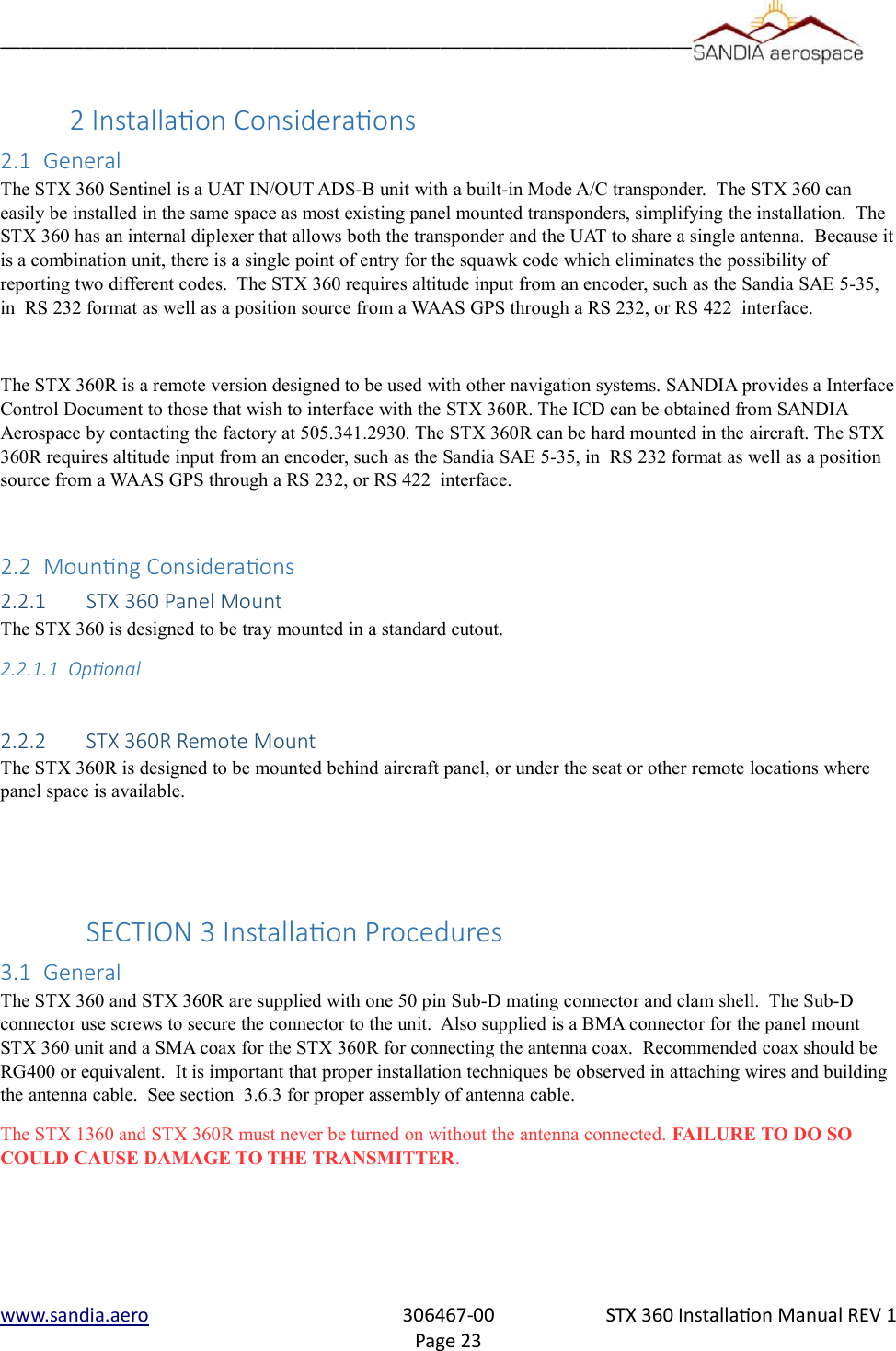
![__________________________________________________________________1.5.1 System Funcons Panel MountThe STX 360 panel mount unit performs the following functions:•UAT ADS-B In and Out [XMT power 30W nom, RCV sensitivity -93dBm] •Built in Mode C transponder [XMT power 200W nom, RCV sensitivity -74dBm] •Built in Diplexer [single antenna installation]•Display of traffic•Display of METARs•Single Entry for squawk code•Built in Ethernet •USB power - +5VDC @ 500mA max•Automatic and Manual Brightness Control•Display of aircraft power•Selectable anonymous mode in VFR•Built in emergency squawk codes•Pass-thru TIS-B, FIS-B, ADS-B state and vector messages•Tray Mounted 1.5.2 System Funcons Remote Mount•UAT ADS-B In and Out [XMT power 30W nom, RCV sensitivity -93dBm] •Built in Mode C transponder [XMT power 53.4dBm, RCV sensitivity -74dBm] •Built in Diplexer [single antenna installation]•SMA connector •Built in Ethernet •USB power - +5VDC @ 500mA max•Pass-thru TIS-B, FIS-B, ADS-B state and vector messages•Anonymous mode in VFR•Built in emergency squawk codeswww.sandia.aero 306467-00 STX 360 Installaon Manual REV 1Page 13](https://usermanual.wiki/Sandia-Aerospace/DAGEDX/User-Guide-3334488-Page-13.png)
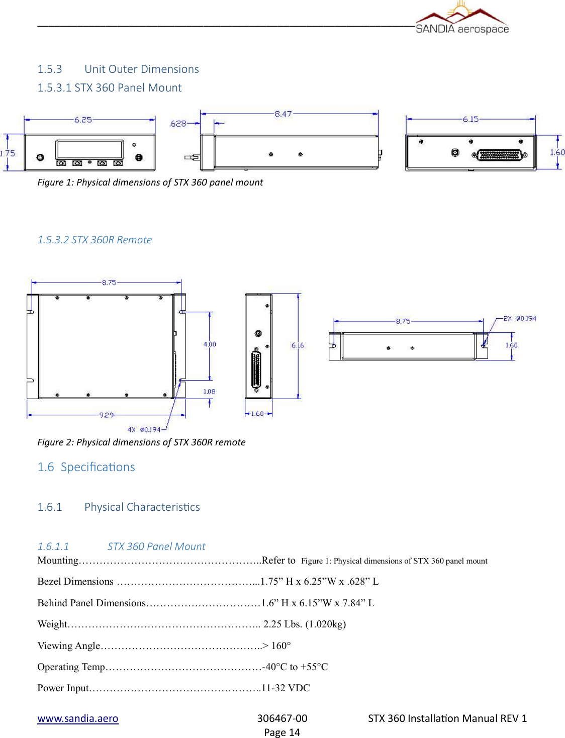
![__________________________________________________________________1.2.4 CerficaonTransponder………………………………………………………..TSO-C74d - Class A ADS-B (UAT)..……………………………………………………TSO-C154c - Class A1S ADS-B (FIS-B)……………………………………………………TSO-C157b - Class 1 ADS-B (TIS-B).…………………………………………………...TSO-C195a - Class C1Software……………………………………………………………DO-178B Level CEnvironmental……………………………………………………...DO-160G (See qualification table) STX 360 (A1C1)X]CAB(SM)XXXXXZBAB[BC][TT]M[A3B2]XXXX STX 360R (A1C1)X]CAB(SM)XXXXXZBAB[BC][TT]M[A3B2]XXXXFCC ID……………………………………………………………..YJL-DAGEDX“The condions and test required for TSO approval of this arcle are minimum performance standards. Itis the responsibility of those desiring to install the arcle either on or within a specific type or class ofaircra to demonstrate that the aircra installaon condions are within the TSO standards. The arclemay be installed only if installaon of the arcle is approved by the Administrator.”www.sandia.aero 306467-00 STX 360 Installaon Manual REV 1Page 17](https://usermanual.wiki/Sandia-Aerospace/DAGEDX/User-Guide-3334488-Page-17.png)
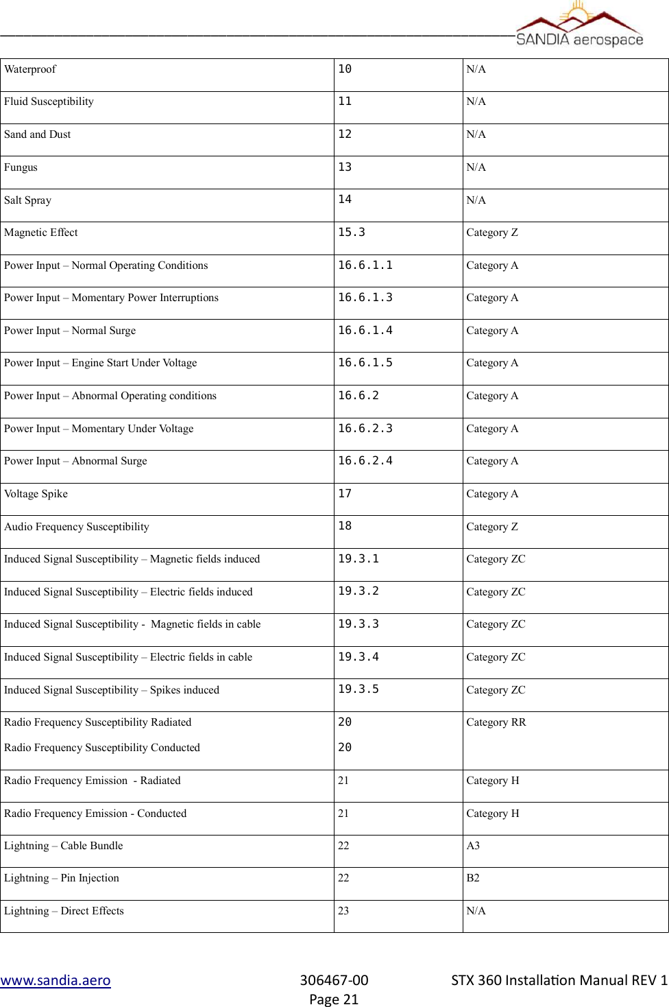
![__________________________________________________________________Environmental Qualification Form for the STX 360 SentinelNOMENCLATURE: STX 360, Airbourne ADSB EquipmentTYPE/MODEL/PART No: STX 360 / 306XXX- [XX] & Electrical Install Kit P/N 306XXXTSO NUMBER: C74d (transponder)C154c (ADSB) - Class A1SC157b ( FIS-B) - Class 1C195a (ADSB) – Class C1MANUFACTURE’S SPECIFICATION AND/OR OTHER APPLICABLE SPECIFICATION:STX 360 INSTALL MANUAL, P/N 306467-00QUALIFICATION TEST PLAN, STX 360 SENTINEL ADSB P/N 901XXX-QTPMANUFACTURER: SANDIA AEROSPACEADDRESS: 3700 OSUNA RD NE, SUITE 711, ALBUQUERQUE, NM 87109REVISION & CHANGE NUMBER OF DO-160: REV G DATED December 2010 DATE OF TESTS: 2016 STX 360 panel mount Environmental categories Test Description DO-160G SEC-TIONConditions and NotesGround Survival and Operating Low Temperature 4.5.1 & 4.5.2 Category A1D1Ground Survival and Operating High Temperature 4.5.3 & 4.5.4 Category A1D1Altitude 4.6.1 Category A1D1Decompression 4.6.2 Category A1D1Overpressure 4.6.3 Category A1D1Temperature Variation 5 Category BHumidity 6.3 Category AOperational Shock and Crash Safety 7 Category BSustained Crash Safety 7.3.3 Test Type 5Vibration-standard 8.2.1.1 Category S – Curve B and MExplosion 9N/AWaterproof 10 N/AFluid Susceptibility 11 N/Awww.sandia.aero 306467-00 STX 360 Installaon Manual REV 1Page 18](https://usermanual.wiki/Sandia-Aerospace/DAGEDX/User-Guide-3334488-Page-18.png)
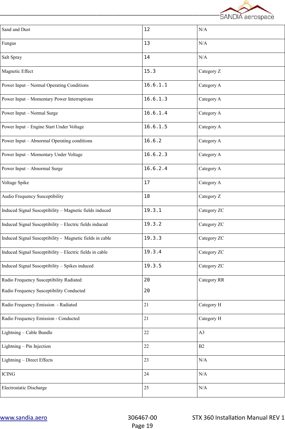
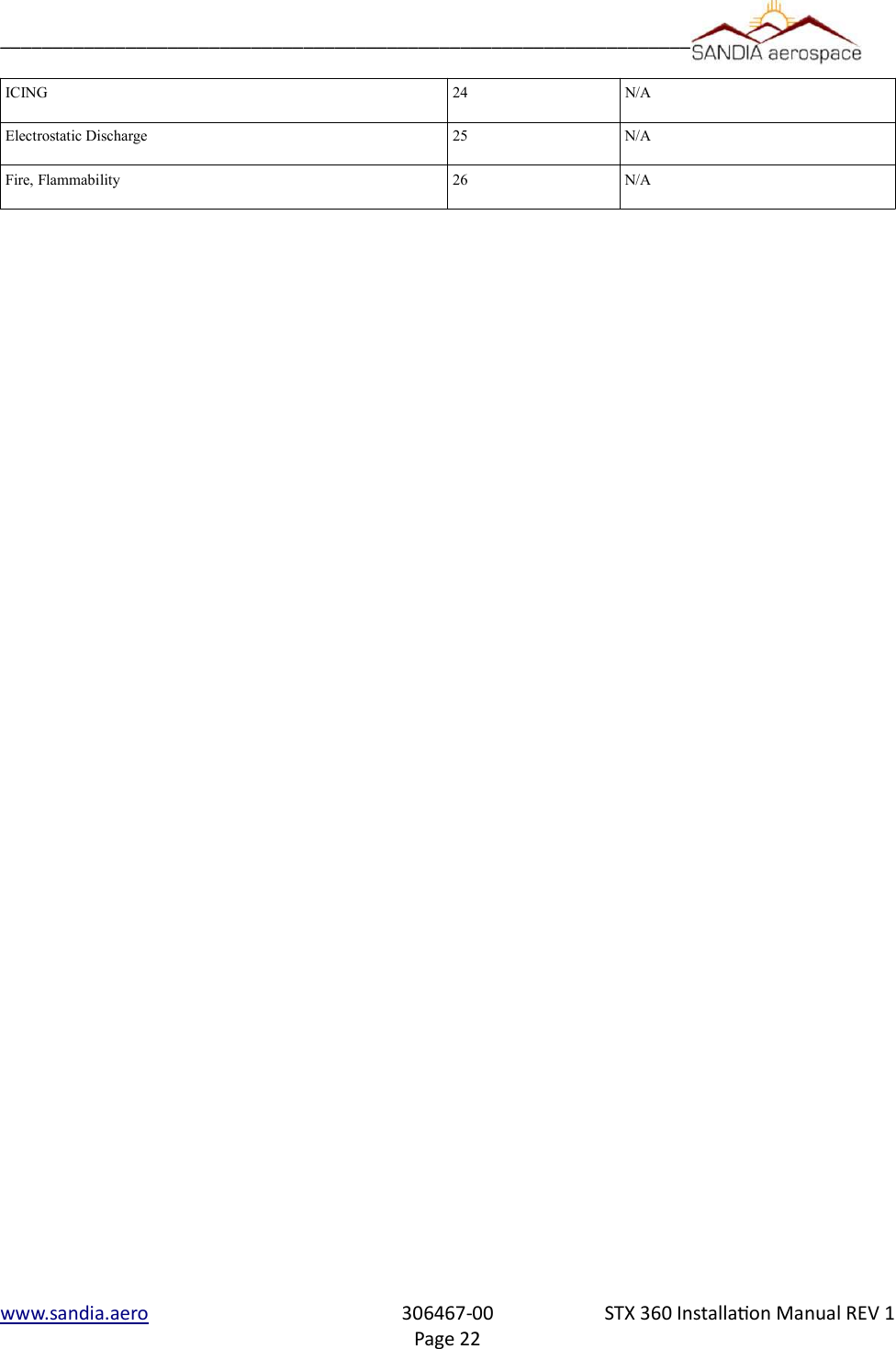
![__________________________________________________________________Fire, Flammability 26 N/AEnvironmental Qualification Form for the STX 360R SentinelNOMENCLATURE: STX 360, Airbourne ADSB EquipmentTYPE/MODEL/PART No: STX 360 / 306XXX- [XX] & Electrical Install Kit P/N 306XXXTSO NUMBER: C74d (transponder)C154c (ADSB) - Class A1HC157b ( FIS-B) - Class 1C195a (ADSB) – Class C1MANUFACTURE’S SPECIFICATION AND/OR OTHER APPLICABLE SPECIFICATION:STX 360 INSTALL MANUAL, P/N 306XXX-XXQUALIFICATION TEST PLAN, STX 360 SENTINEL ADSB P/N 901XXX-QTPMANUFACTURER: SANDIA AEROSPACEADDRESS: 3700 OSUNA RD NE, SUITE 711, ALBUQUERQUE, NM 87109REVISION & CHANGE NUMBER OF DO-160: REV G DATED December 2010 DATE OF TESTS: 2016Test Description DO-160G SECTION Conditions and NotesGround Survival and Operating Low Temperature 4.5.1 & 4.5.2 Category A1D1Ground Survival and Operating High Temperature 4.5.3 & 4.5.4 Category A1D1Altitude 4.6.1 Category A1D1Decompression 4.6.2 Category A1D1Overpressure 4.6.3 Category A1D1Temperature Variation 5 Category BHumidity 6.3 Category AOperational Shock and Crash Safety 7 Category BSustained Crash Safety 7.3.3 Test Type 5Vibration-standard 8.2.1.1 Category S – Curve B and MExplosion 9N/Awww.sandia.aero 306467-00 STX 360 Installaon Manual REV 1Page 20](https://usermanual.wiki/Sandia-Aerospace/DAGEDX/User-Guide-3334488-Page-20.png)
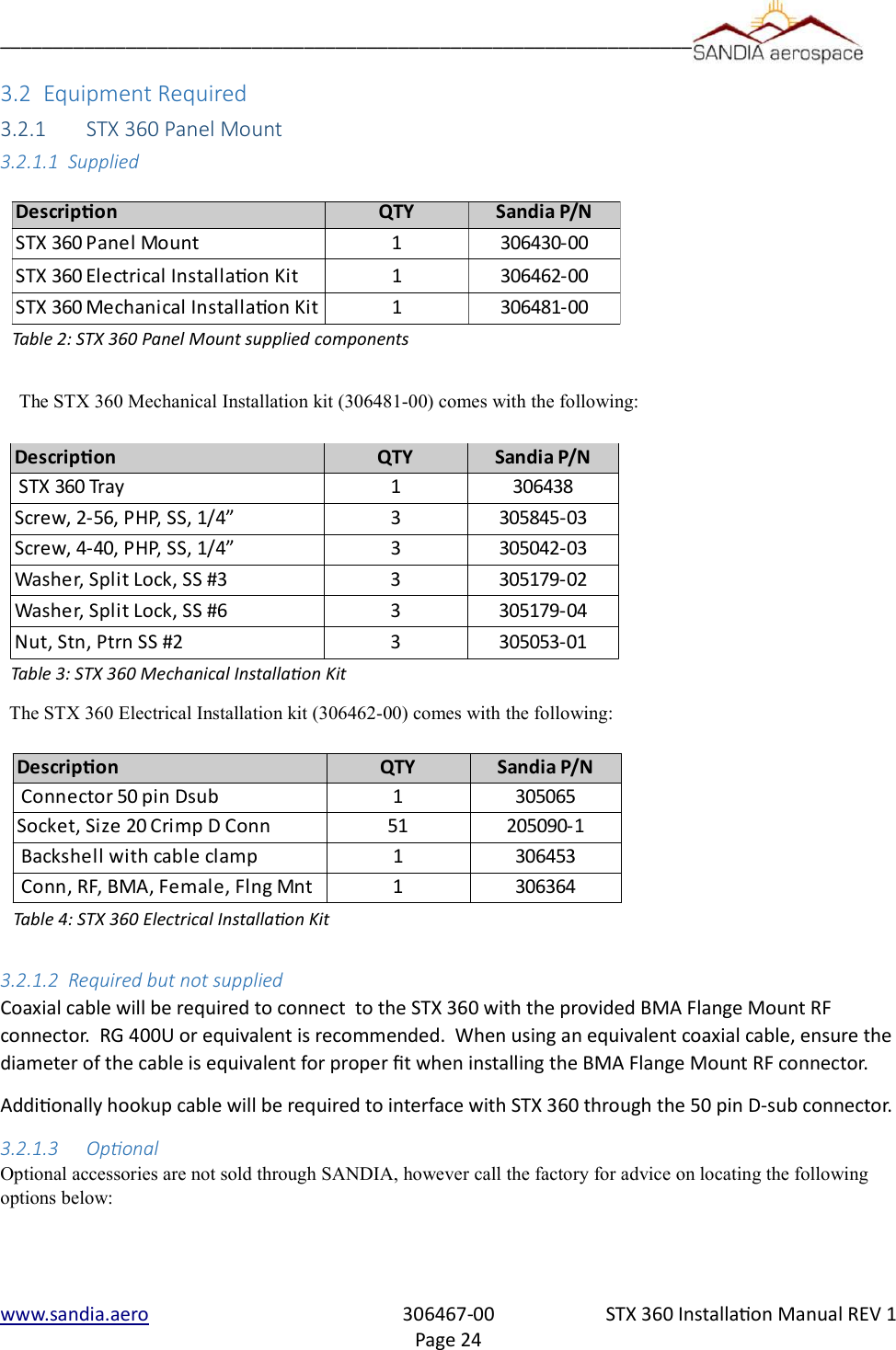
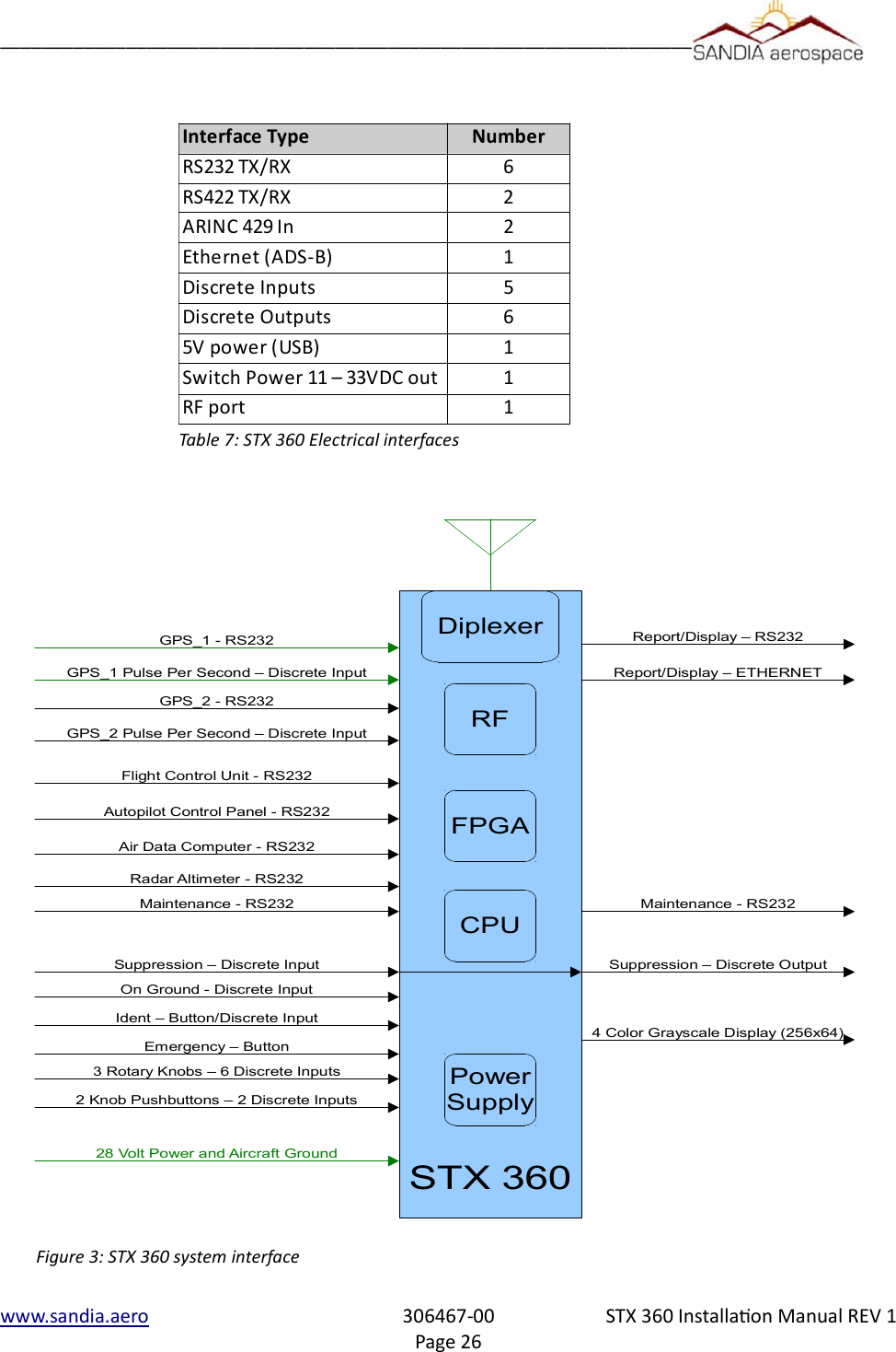
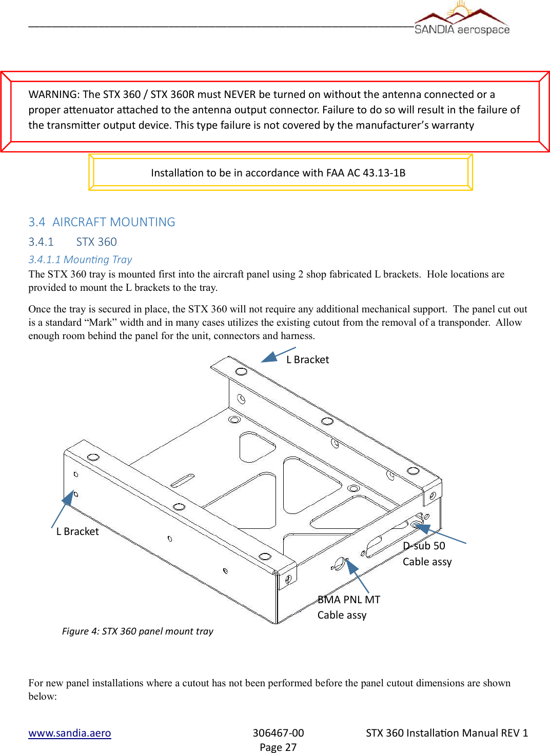
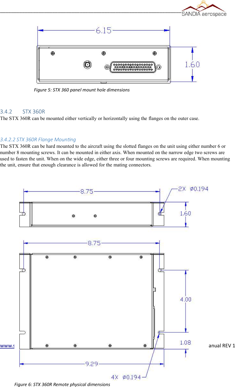
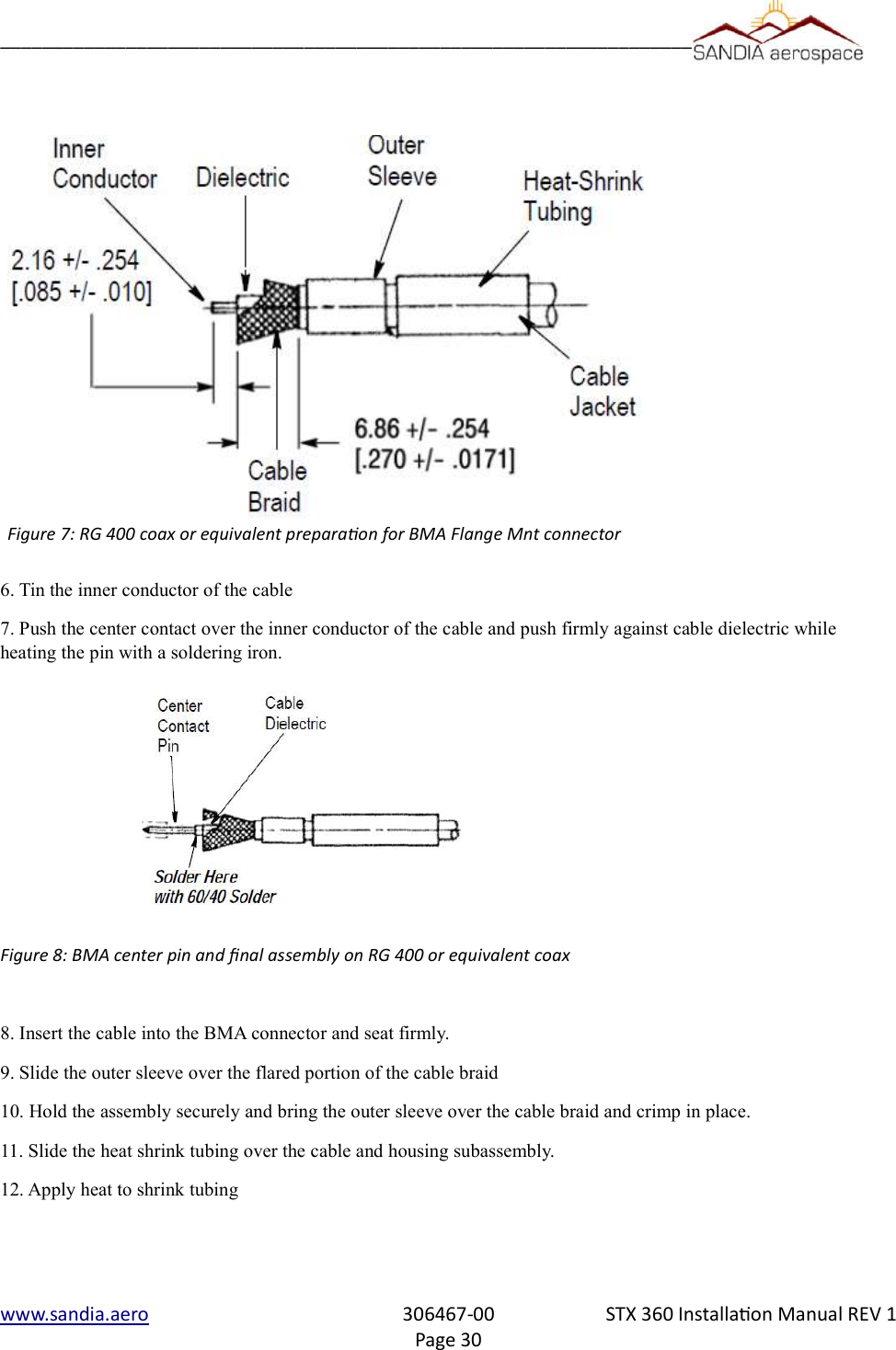
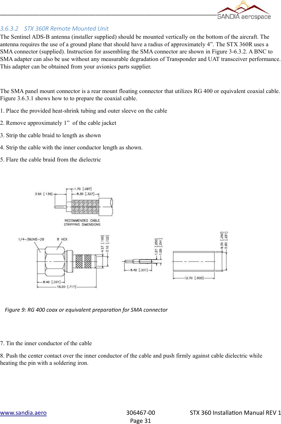
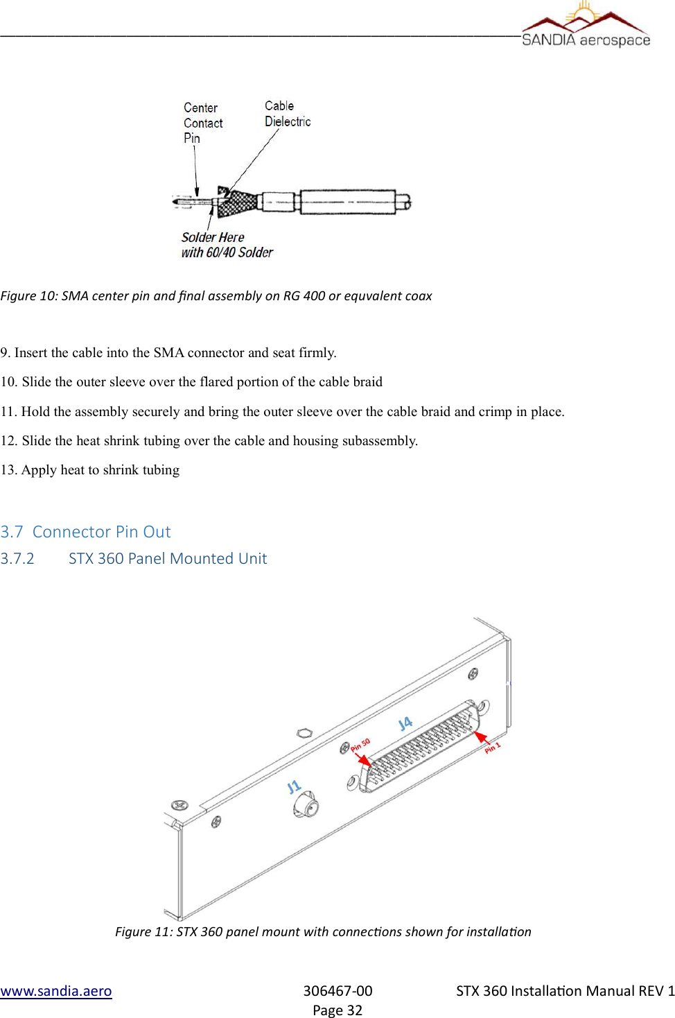
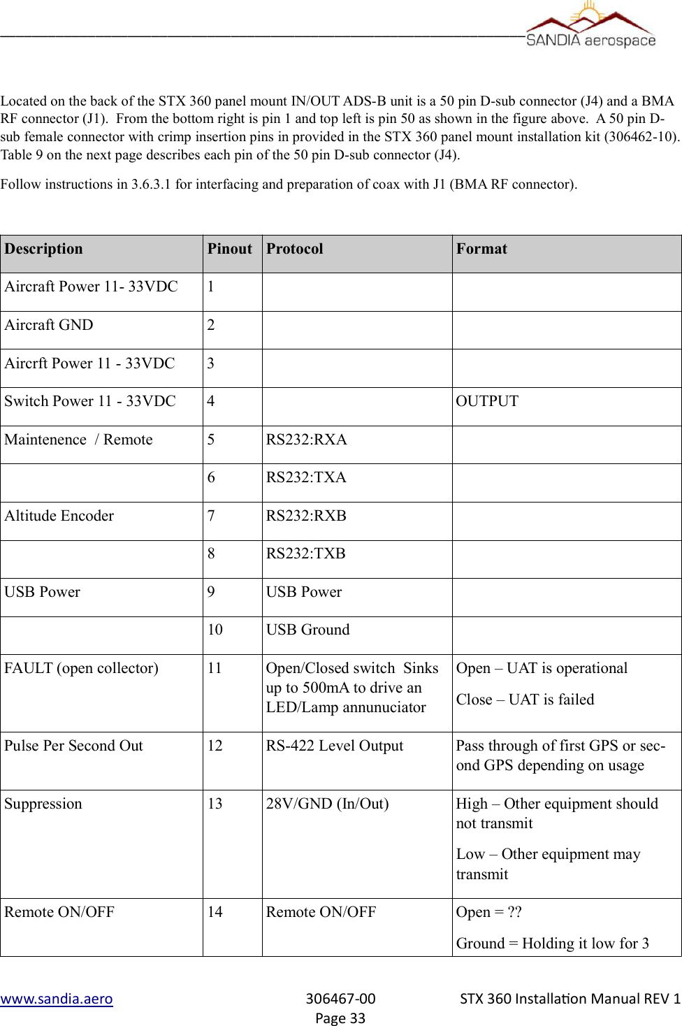
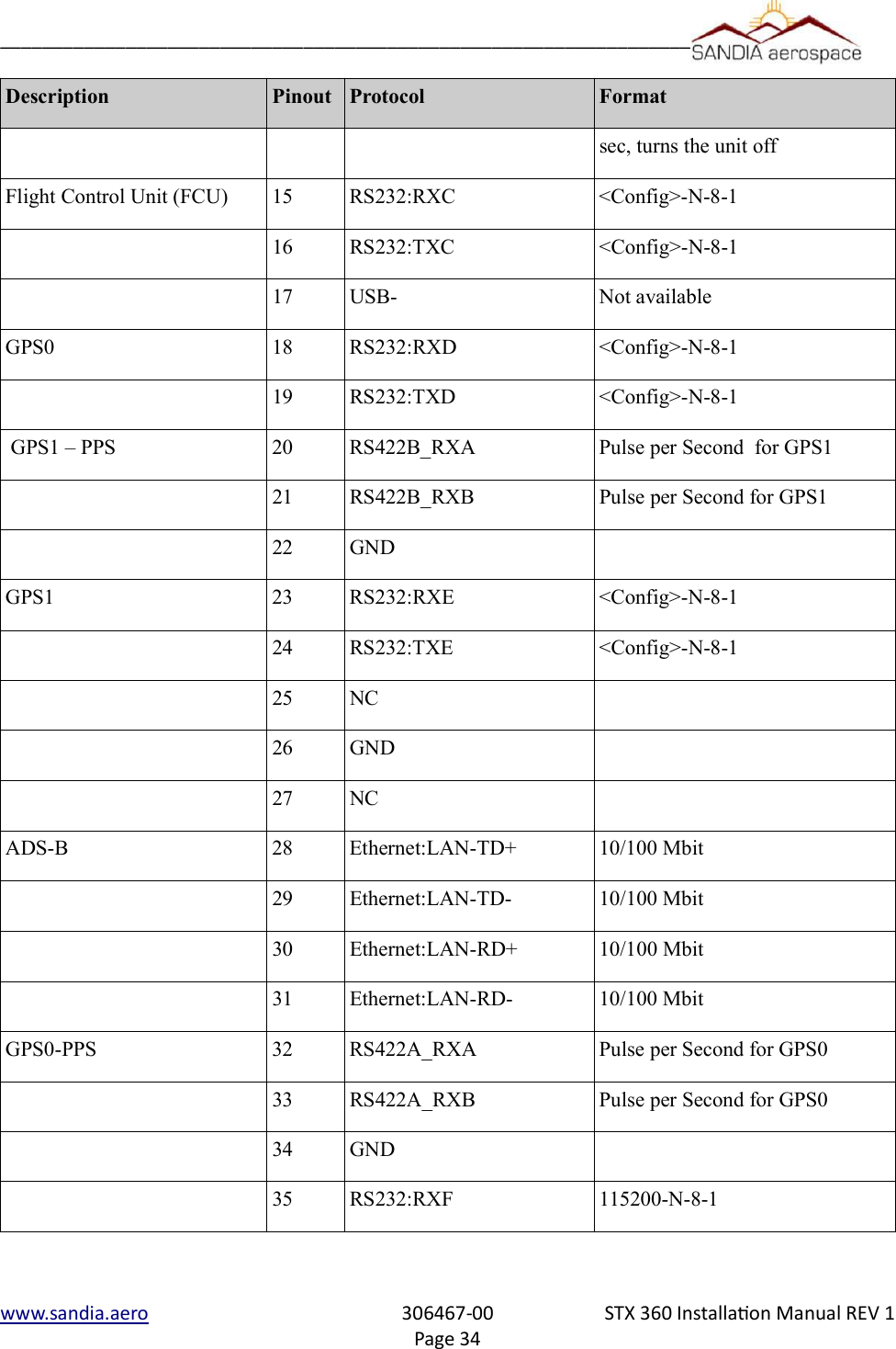
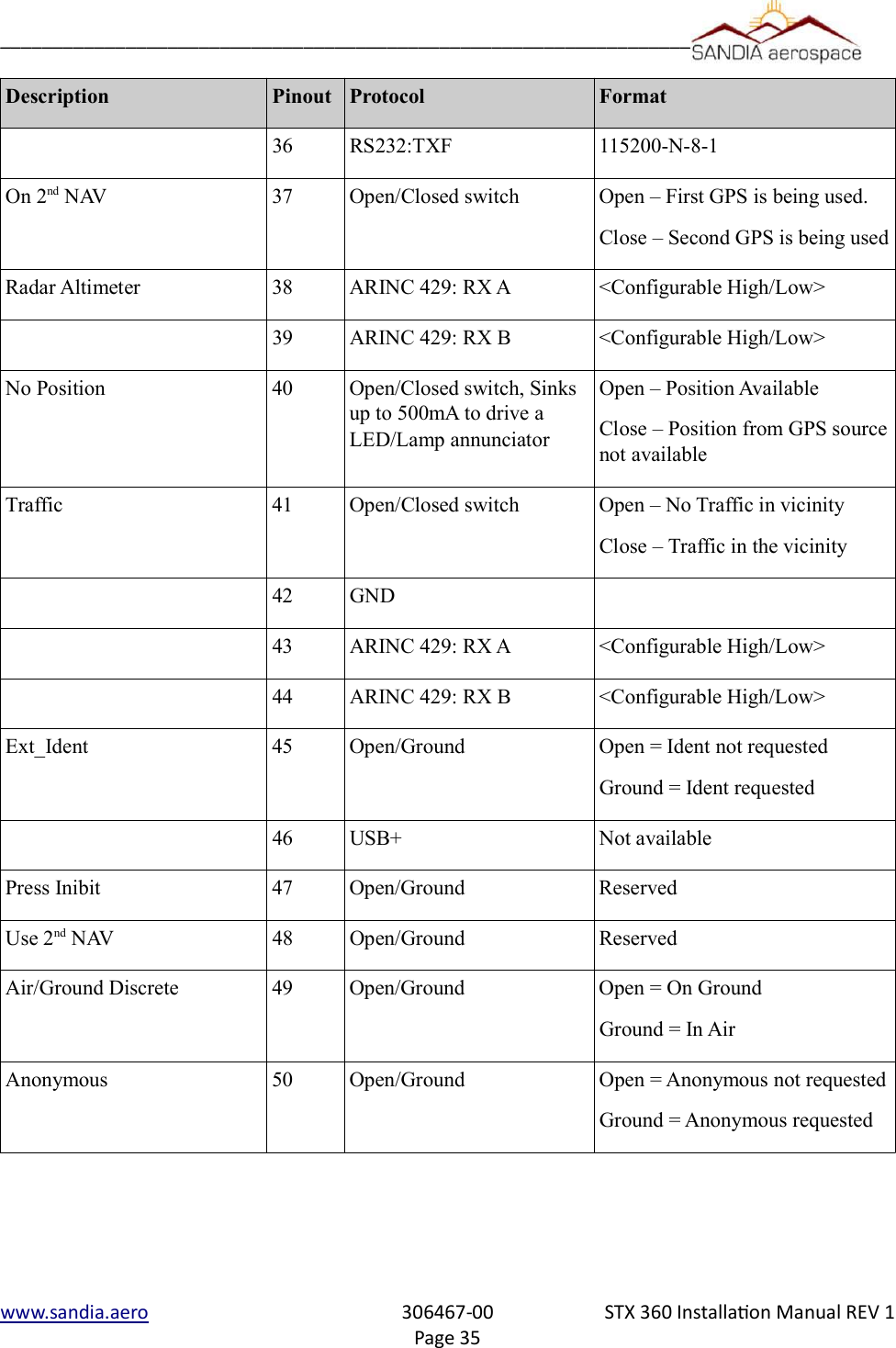
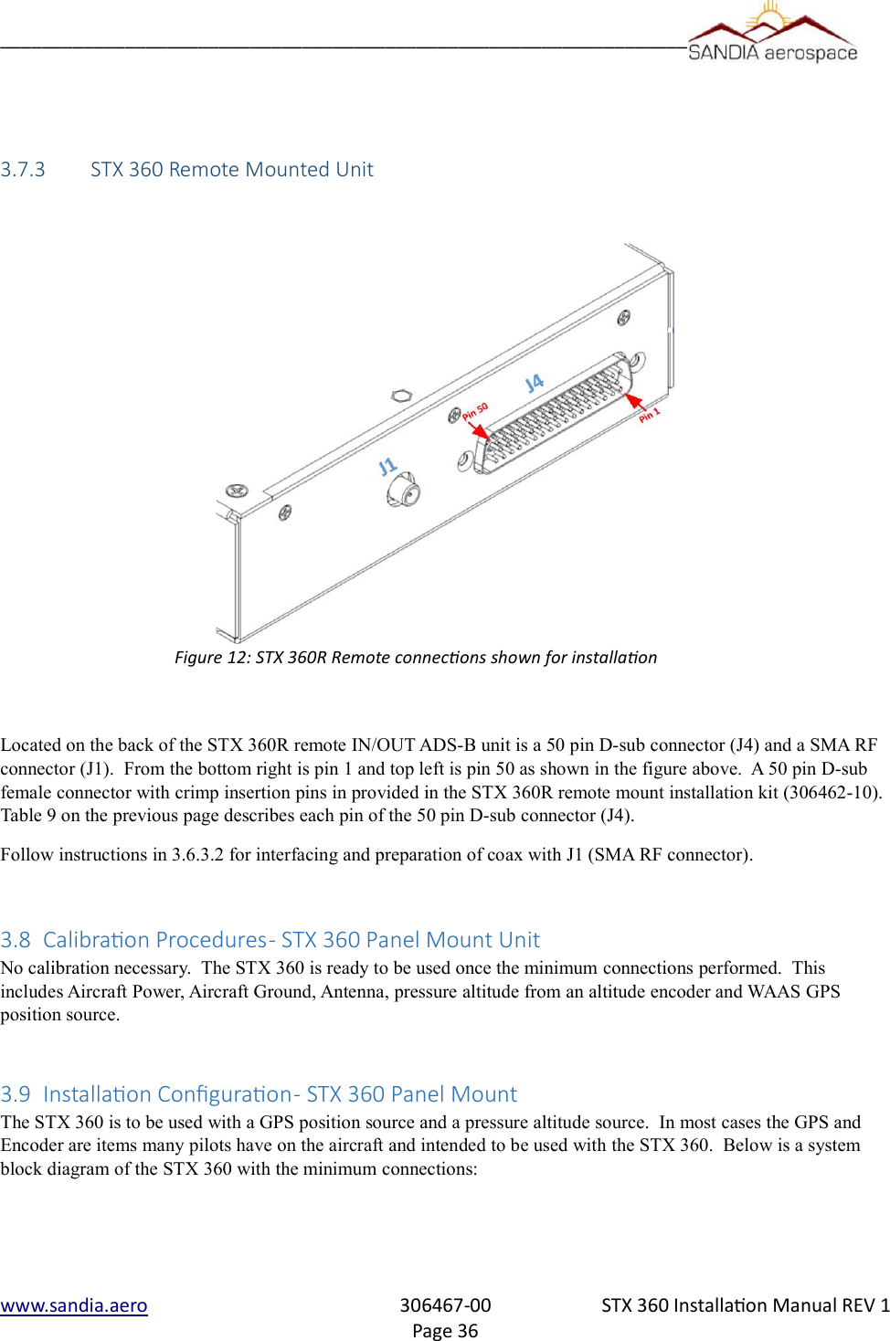
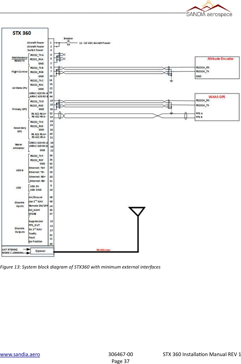
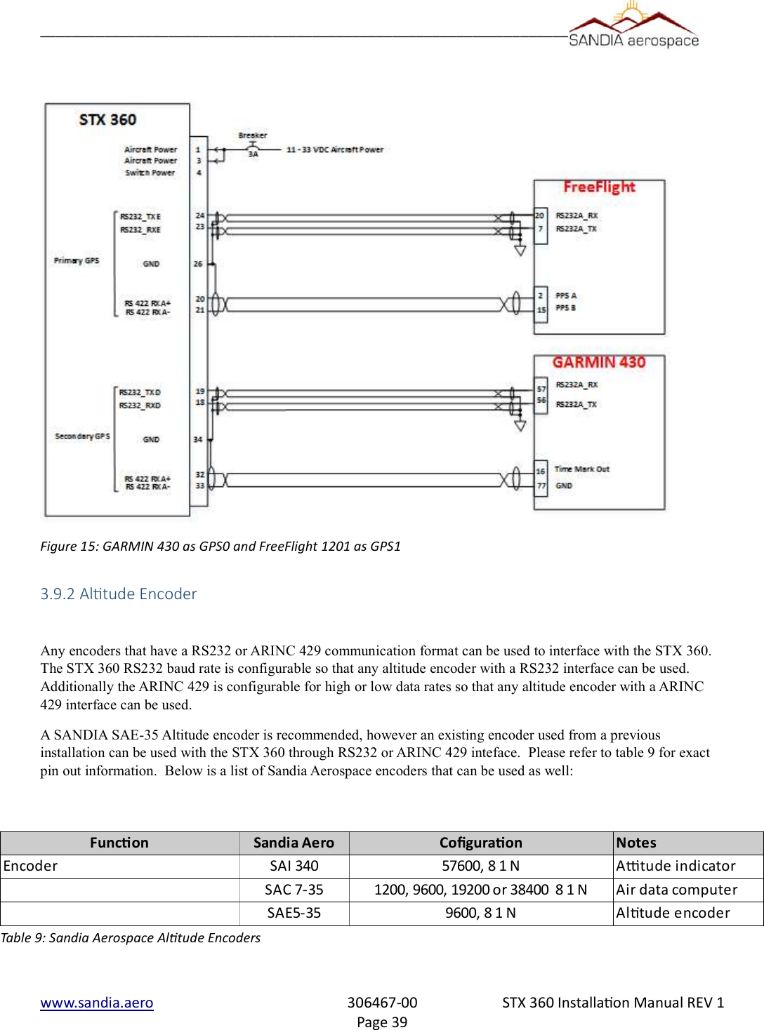
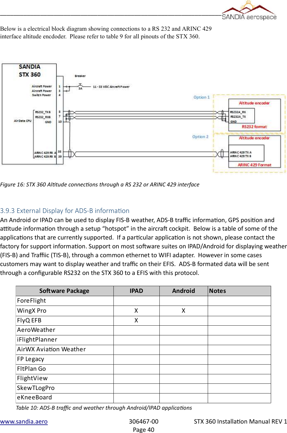
![__________________________________________________________________3.6 Electrical ConneconThe STX 360 and STX 360R are designed to operate on 11-32Vdc without any special wiring considerations. Powershould be supplied from aircraft power through a 2 amp fuse or circuit breaker to protect the Sentinel ADS-B unit. The STX 360 and STX 360R also output unswitched aircraft power (J4 pin 4 – see section 3.7.1 for more details ) tooperate other avionics. If this output is used (a Maximum of 1 Amp), the fuse or breaker size should be adjusted to accommodate the other system. Power and ground wires are 20 AWG. All other wires are 22 AWG unless otherwise noted. 3.6.1 STX 360 Panel Mounted UnitThe minimum installation for an operable STX 360 is Aircraft Power, Aircraft Ground, Antenna, pressure altitude from an altitude encoder and WAAS GPS position source. Aircraft power and ground are both found on J4 of the 50 pin D-sub connector. The STX 360 receives encoder altitude data in either RS 232 or ARINC 429. The STX 360 receives GPS position source through RS232 or RS422. The STX 360 has the ability to have two positions sources connected through either protocol as a primary or secondary. A radar altimeter can also be connected through a configurable high/low ARINC429 interface. ADS-B information such as TIS-B and FIS-B can be sent through ethernet or a configurable RS232 interface. An additional RS232 [38400-N-8-1] can be used for a flight control unit.An additional RS232 [115200-N-8-1] is used for remote operation or maintenance port. See table 1 for all connection details on D-sub 50 (J4).3.6.2 STX 360R Remote Mounted UnitThe minimum installation for an operable STX 360R is Aircraft Power, Aircraft Ground, Antenna, pressure altitude from an altitude encoder and WAAS GPS position source. Aircraft power and ground are both found on J4 of the 50 pin D-sub connector. The STX 360 receives encoder altitude data in either RS 232 or ARINC 429. The STX 360 receives GPS position source through RS232 or RS422. The STX 360 has the ability to have two positions sources connected through either protocol as a primary or secondary. A radar altimeter can also be connected through a configurable high/low ARINC429 interface. ADS-B information such as TIS-B and FIS-B can be sent through ethernet or a configurable RS232 interface. An additional RS232 [38400-N-8-1] can be used for a flight control unit.An additional RS232 [115200-N-8-1] is used for remote operation or maintenance port. See table 1 for all connection details on D-sub 50 (J4).3.6.3 Antenna Connector3.6.3.1 STX 360 Panel Mounted UnitThe STX 360 panel mount ADS-B antenna (installer supplied) should be mounted vertically on the bottom of the aircraft. The antenna requires the use of a ground plane that should have a minimum radius of approximately 4”. TheSTX 360 uses a BMA Panel mount RF connector (supplied). Instructions for assembling the BMA connector are shown below and a graphical stripping dimensions are shown in Figure 3-6.3.1 . The BMA panel mount connector is a rear mount floating connector that utilizes RG 400 or equivalent coaxial cable.Figure 3.6.3.1 shows how to to prepare the coaxial cable. 1. Place the provided heat-shrink tubing and outer sleeve on the cable2. Remove approximately 1” of the cable jacket 3. Strip the cable braid to length as shown4. Strip the cable with the inner conductor length as shown.5. Flare the cable braid from the dielectricwww.sandia.aero 306467-00 STX 360 Installaon Manual REV 1Page 29](https://usermanual.wiki/Sandia-Aerospace/DAGEDX/User-Guide-3334488-Page-29.png)
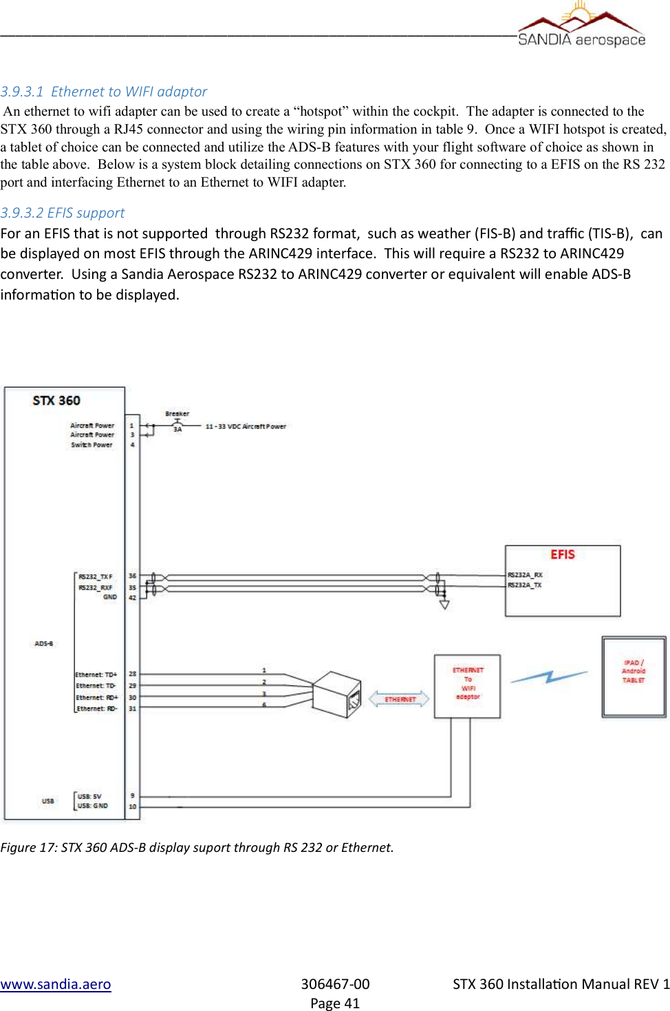
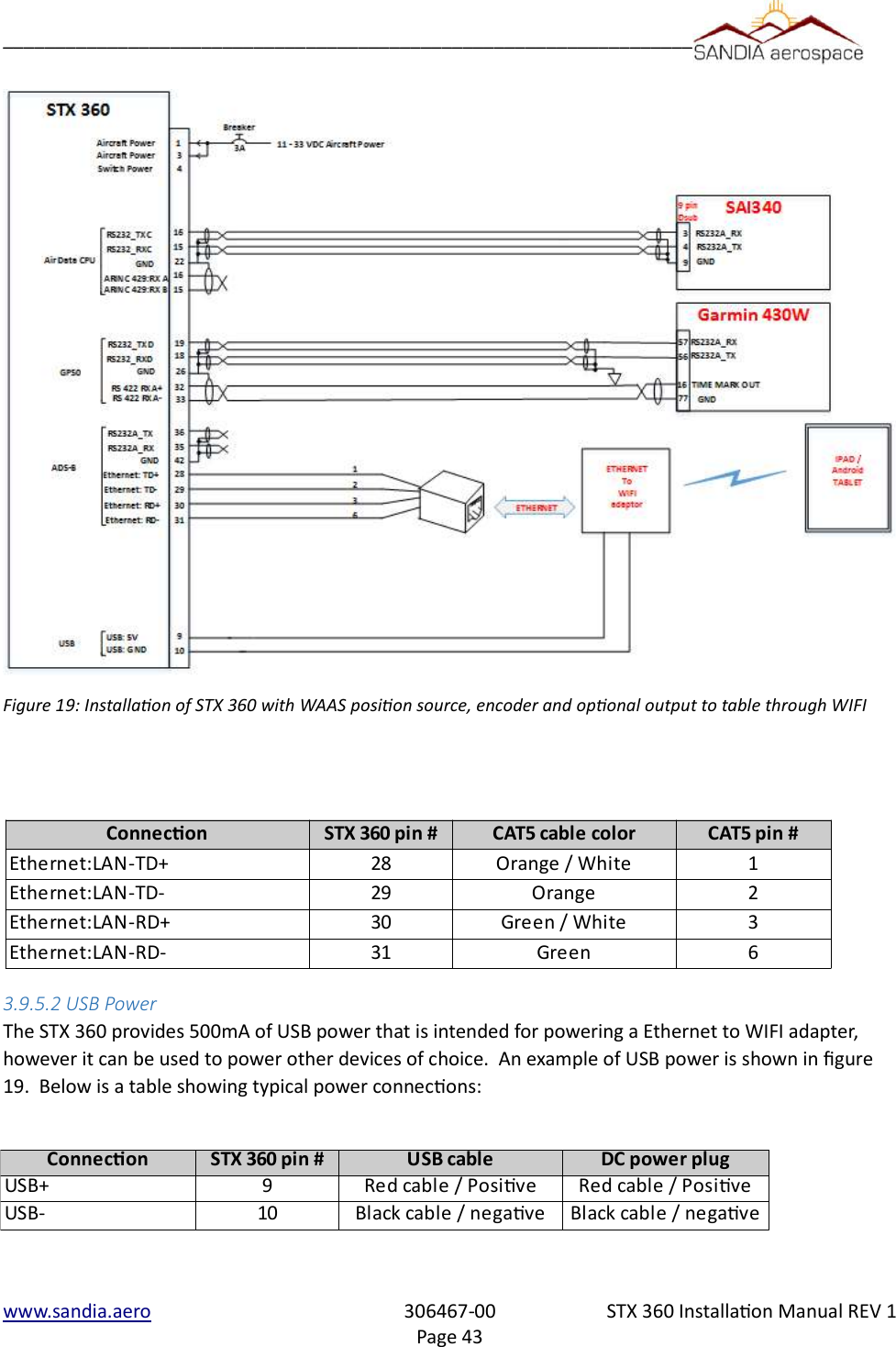
![__________________________________________________________________3.9.4 Annuciator conneconsThe Annunciator circuit supplies a ground. Do not connect voltage directly to this input as it may cause damage to internal circuitry. The annunciator light is required when no display is used and alerts the pilot when a fault or posion source has been lost.1. All wires should be a minimum of 22 AWG.2. ADS-B annunciation controls necessary for installations without a display.3. Use MS25041-8 light with [28VDC dimmer] MS25237-327 lamp or [14VDC dimmer] MS25237-330 lamp.4. Lamp voltage from annunciator dimmer circuit3.9.5 Typical installaon Below is a typically installation the includes the STX 360, SAI 340 attitude indicator (Encoder) , WAAS position source and the use of Ipad/Android tablet to display the ADS-B data using an application of choice.3.9.5.1 Ethernet to WIFIEthernet connection on the STX 360 may be used to interface directly to a device or through a Ethernet to WIFI adapter. Below are the necessary connections to interface the STX 360 to a CAT5 patch cable. Above in figure 19 is an example of wiring an CAT5 cable and below is a table showing STX 360 pin number with a CAT5 patch cable.www.sandia.aero 306467-00 STX 360 Installaon Manual REV 1Page 42Figure 18: Annunciaor connecons for STX 360](https://usermanual.wiki/Sandia-Aerospace/DAGEDX/User-Guide-3334488-Page-42.png)
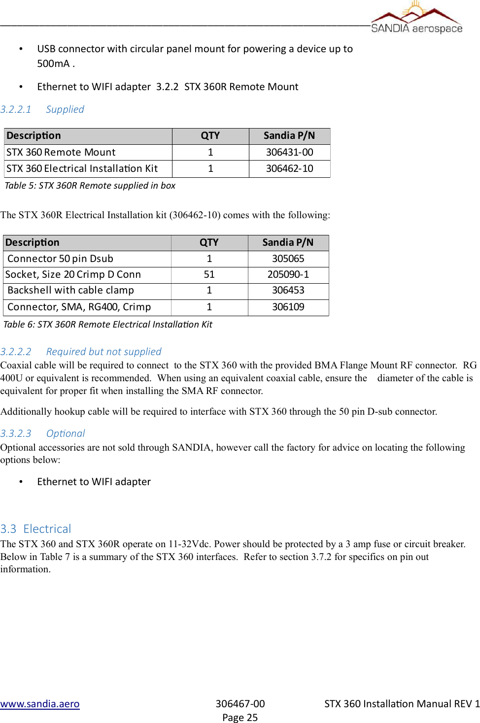
![__________________________________________________________________software information. Each of these pages can be selected by rotating the Select knobclockwise or counter clockwise to the highlighted page. Once a page is selected, the Select knob, Data knob and Data button are used to change/select values on each page.1 – [MODE] Left Encoder with push button2 – VFR Button3 – IDENT Button4 – Pages available on main menu. Highlighted bar is the current page.5 – Message Button The STX 360 displays errors/noficaons in the Message page. Message indicator field (le side of dis-play) blinks when a new message arrives and stays highlighted as long as there are acve messages. Once all the messages becomes inacve, the highlight goes away. The system could generate the follow-ing five messages.When multiple messages are active, the messages shall be listed on a scrollable list based on their priority as listed in Table 13. The highest priority message will be listed at the top.www.sandia.aero 306467-00 STX 360 Installaon Manual REV 1Page 48Figure 21: STX 360 front panel funconalityTable 13: STX 360 messages and priorityMessage Priority LevelINVALID ICAO ADDRESS 1GPS POSITION ERROR 2TRANSMIT INCAPABLE 3GDL90 FAULT 4ANONYMOUS NOT ACTIVE 5EMERGENCY NOT ACTIVE 6](https://usermanual.wiki/Sandia-Aerospace/DAGEDX/User-Guide-3334488-Page-48.png)
![__________________________________________________________________6 – Emergency ButtonEmergency button adds the convenience of built in emergency squawk codes.7 – Light Sensor8 – [Select / Data ] Dual concentric Encoder with push button4.3.1 Traffic display screenWhen the unit powers up, the STX 360 defaults to the first page. This first page displays the traffic. Items that can be changed on this window are:Each of these items above can be easily changed by first rotating the Data knob one rotation and then rotating the Select knob to the desired function (highlighted). Once the desired function is highlighted, the Data knob is rotated to pick the correct setting by rotating clockwise or counter clockwise. 4.3.2 METAR display screenRotating the Select knob clockwise one click (page 2) displays the METAR page. METARs are acquired over time through ground stations and aircraft. The newest airport information will show on top while the last will be the bottom of the list. The left pane displays the airport and the right pane displays the METAR data. 4.3.3 GPS Informaon screenRotating the Select knob clockwise two clicks (page 3) displays the GPS page. This page displays the latitude and longitude, GPS altitude, UTC time, ground speed and On Ground/In air status. This allows the user to easily see GPS information in a clear and concise format. GPS page shall display above listed information if they are available, otherwise dashes are displayed.4.3.4 brightness display screenThe brightness page displays/controls the current LCD brightness in terms of percentage. Turning the Top Right Encoder clockwise/counter clockwise while on Brightness Page shall increase/decrease thebrightness of the display in between 4% to 100% and set the brightness to the selected value disabling the auto brightness adjustment.4.3.5 CALL SIGN / TAIL number display screenThe call sign/tail number page allows the user to change the flight id to match to the aircraft. Additionally the mode C transponder anonymous mode can be changed from this screen.. It must be noted that the anonymous mode can only be used in VFR mode. The following steps shall be followed to edit a FLIGHT ID.1. Press Right Encoder Switch to enable field selection on the current page.2. Use Bottom Right Encoder to select the FLIGHT ID for editing.www.sandia.aero 306467-00 STX 360 Installaon Manual REV 1Page 49Field Possible ValuesRange 0.2, 0.5, 1, 2, 3, 4, 5, 6, 7, 8, 9, 10, 20, 40 nmTraffic Type BOTH, ON GND, IN AIRAltitude Disc in Flight Level ±10,15,20,25,30,35,40,45,50,60,70,80,90,99Track Type TRK UP, NRTH UP Ownship Position Bottom of the screen to Top of the screen.](https://usermanual.wiki/Sandia-Aerospace/DAGEDX/User-Guide-3334488-Page-49.png)

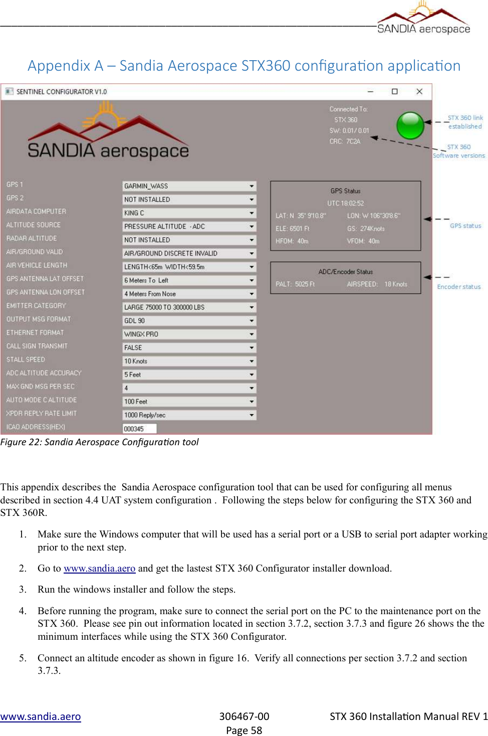
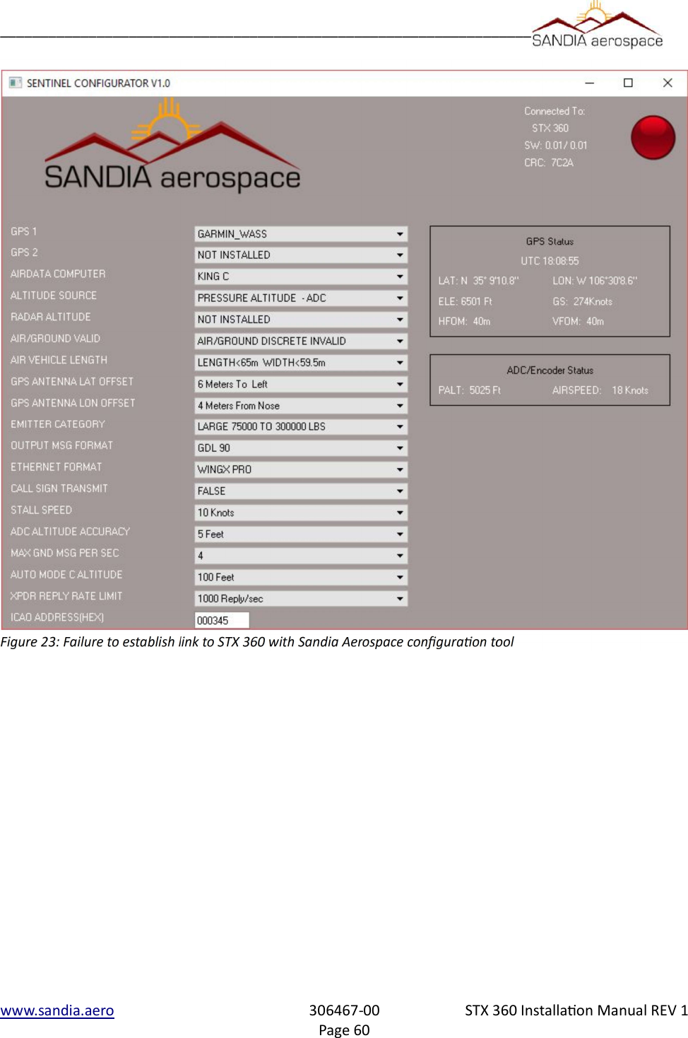
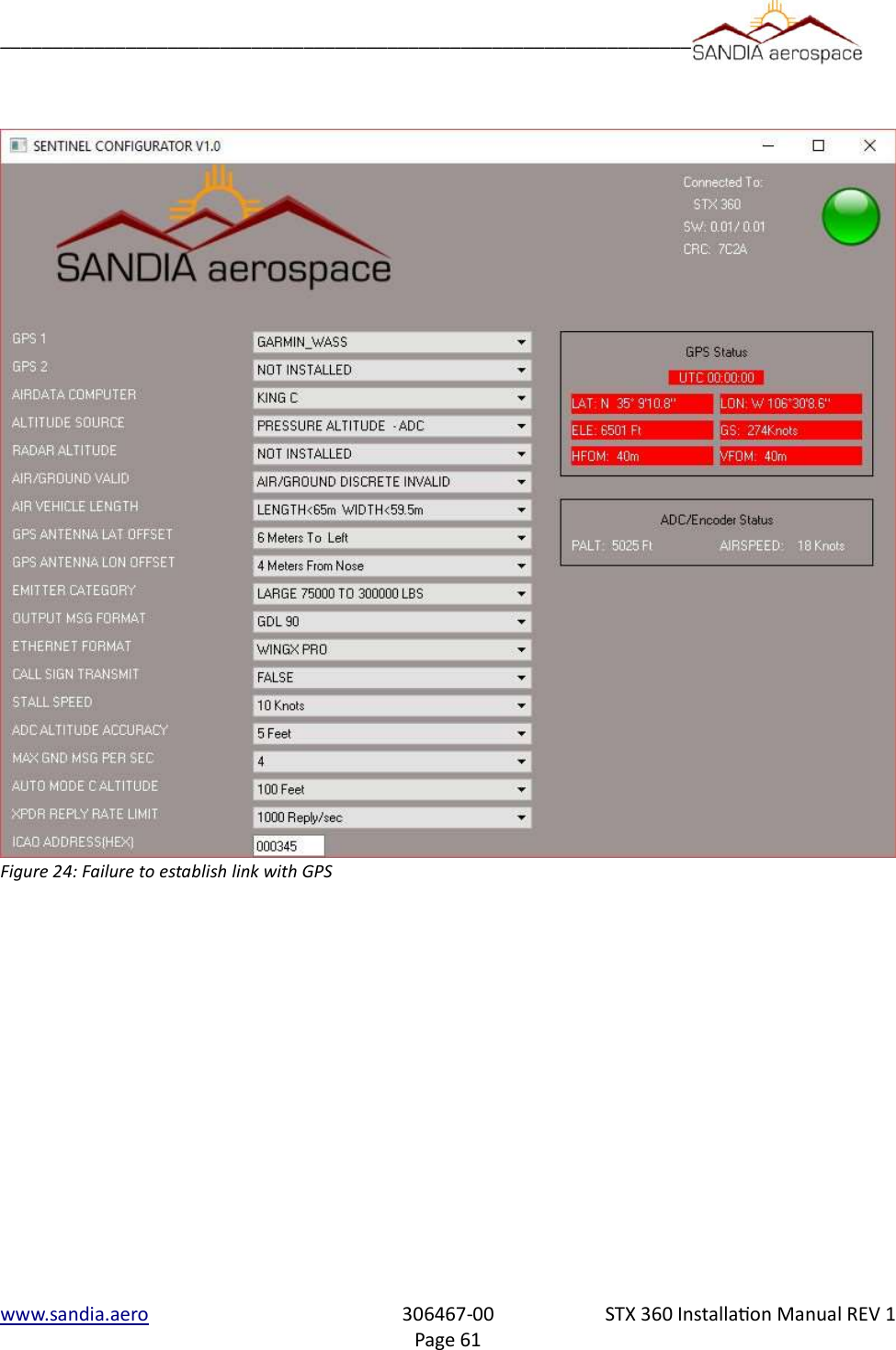
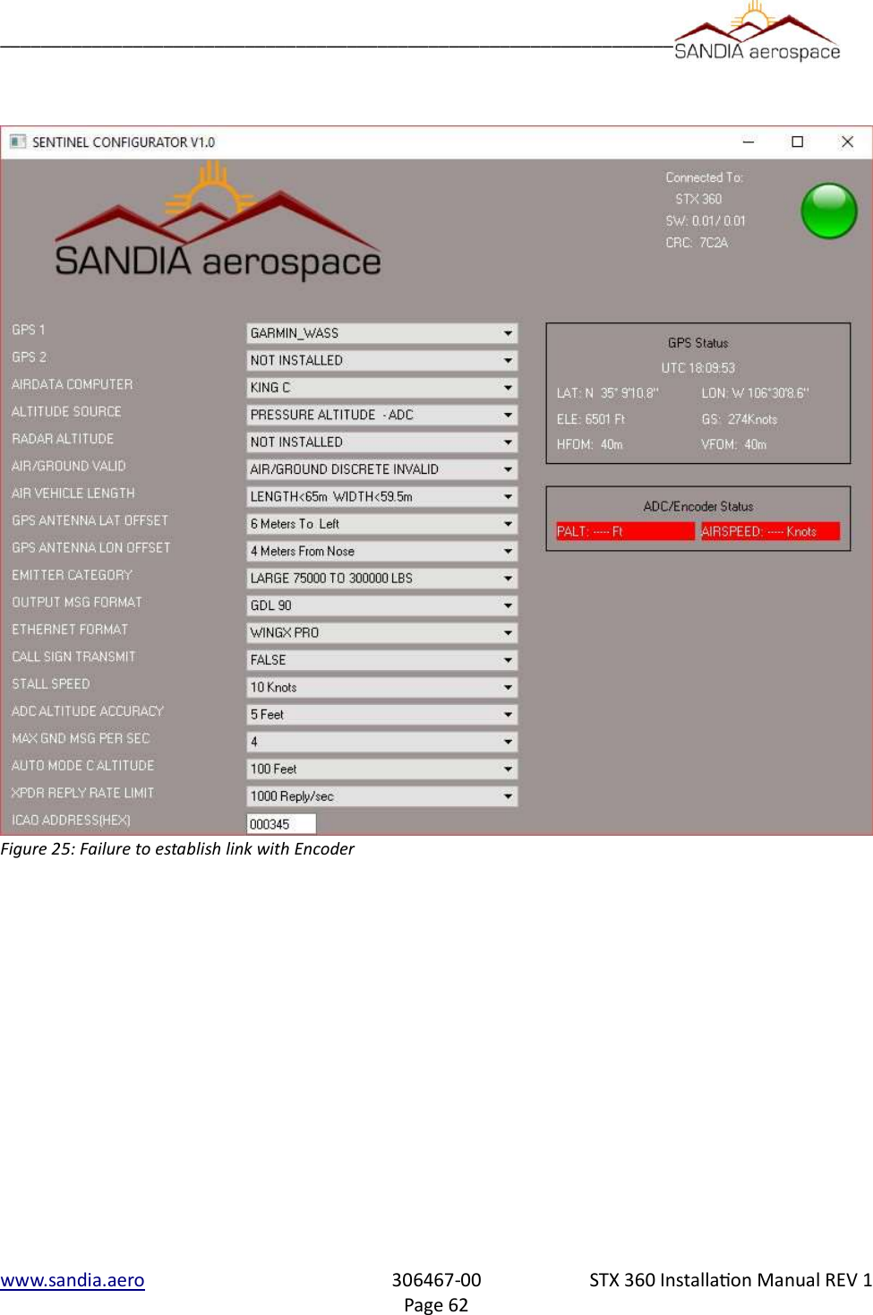
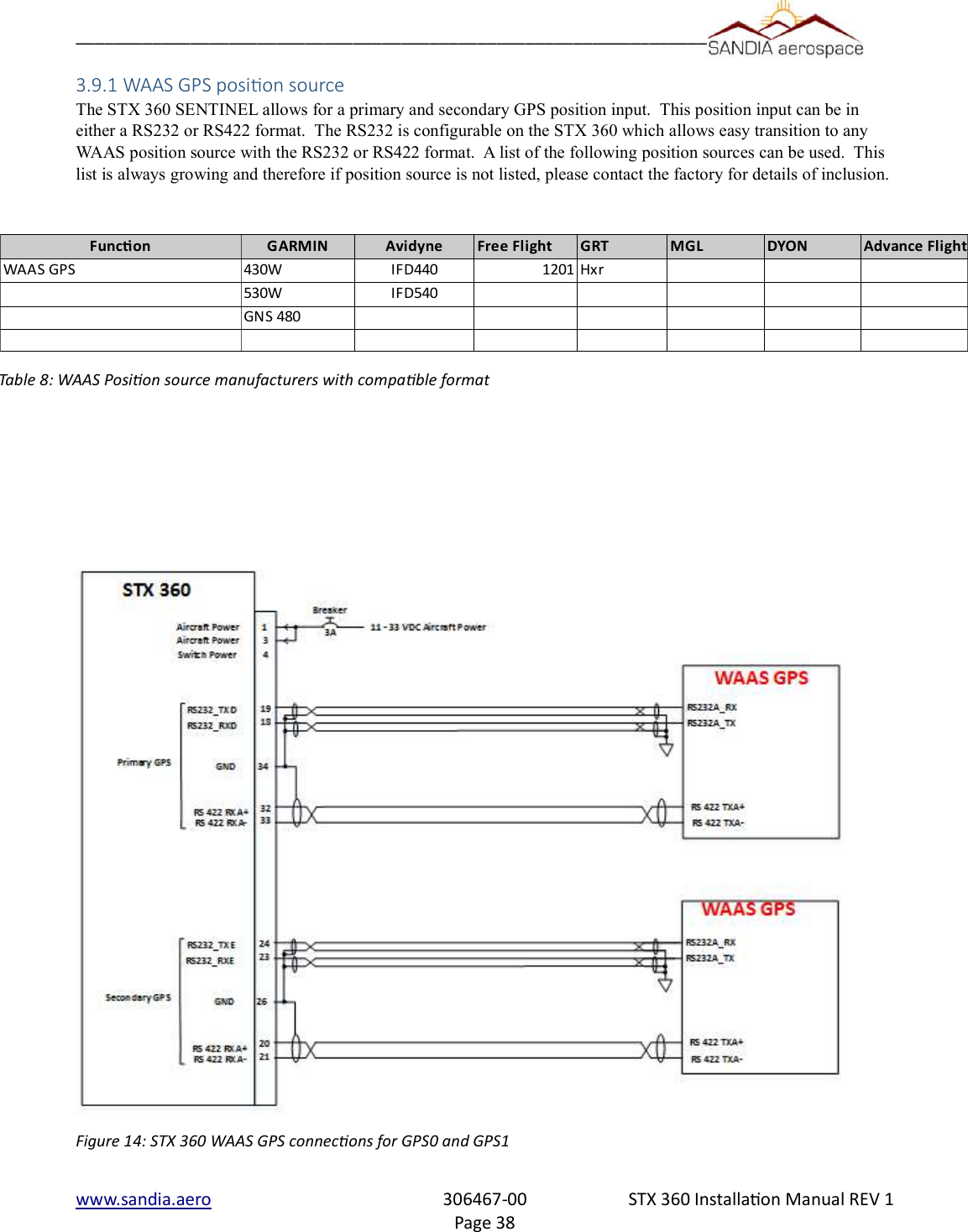
![__________________________________________________________________6. Connect an WAAS GPS source as shown in figure 14. Verify all connections persection 3.7.2 and section 3.7.3.7. Ensure the STX 360 antenna port is connected to a load /antenna prior to powering up the unit.8. Power up the STX 360, the green light should be present. If not check the wiring connection to the maintenance port [pins 6, 7 ].9. Once connections are made, run the software. The software will try to communicate with the STX 360. If a connection is made, a green light will be visible on the top right corner of the software. This indicates a communication link has been established. 10. Select the proper GPS timing source from the pull down menu. 11. Power GPS and make sure it is connected to the STX 360. If the connections are correct, GPS status information should be present. If only dotted lines are present, review the connections between the STX 360 and the GPS. Additionally make sure the correct GPS is selected from the pull down menu.12. Select the proper encocoder from the pull down menu. 13. Power Encoder and make sure it is connected to the STX 360. If the connections are correct, encoder statusinformation should be present. If only dotted lines are present, review the connections between the STX 360 and the encoder. Additionally make sure the correct encoder is selected from the pull down menu.14. The other pull down menus are for configuring the STX 360 and as long as the STX 360 light is green, the data selected will be sent to the STX 360.Below are error conditions when STX 360 link is not established, GPS link failure and Encoder link failure:www.sandia.aero 306467-00 STX 360 Installaon Manual REV 1Page 59](https://usermanual.wiki/Sandia-Aerospace/DAGEDX/User-Guide-3334488-Page-59.png)