Sandia Aerospace DAGEDX AVIATION TRANSPONDER User Manual STX360 032417 5ER
Sandia Aerospace Corporation AVIATION TRANSPONDER STX360 032417 5ER
User Manual

__________________________________________________________________
STX360 /STX360R
Installation Manual
www.sandia.aero 306467-00 STX 360 Installaon Manual REV 1
Page 1

__________________________________________________________________
This document and the informaon contained herein is the proprietary data of SANDIA aerospace
Corporaon. No part of this document may be transmied, reproduced, or copied in any form or by any
means without the prior wrien consent of SANDIA aerospace. Due to SANDIA aerospace’s connued
product and quality improvement programs, informaon contained in this document is subject to
change without prior noce Copyright 2017 SANDIA aerospace Corporaon, All right rights reserved.
Printed in USA
Information Subject To Export Control Laws
Revision Date Description Approval
1-ER 01/25/17 Initial Release Gabriel Martinez
2-ER 01/27/17 Updated page 2
menu items
Gabriel Martinez
3-ER 02/02/17 Page 33,42
updates
Gabriel Martinez
4-ER 03/07/17 Warning label
added
Gabriel Martinez
5-ER 03/24/17 emmision
designator
Gabriel Martinez
Sandia Aerospace Three year limited warranty
“SANDIA Aerospace warrants to the end purchaser of SANDIA Aerospace products, that said products are
free from defects in material and workmanship under normal use and service. The manufacturers obligation
under this warranty shall be limited to repair, replacement, or exchange of any part or parts, at SANDIA
Aerospace’s option, which may thus prove defective under normal use and service within three years from
the date of installation on aircraft of original purchaser, and which upon examination by the manufacturer,
shall disclose to its satisfaction to be thus defective. This warranty is expressly in lieu of all other
warranties, expressed or implied including warranties of merchantability and fitness for use, and of all other
obligations or liabilities on our part. We neither assume, nor authorize any person to assume for us, any
other liability in connection with the sale of SANDIA Aerospace products. This warranty shall not apply to
these parts, nor any part thereof, which has been subject to accident, negligence, alteration, abuse, or
misuse. We make no warranty whatsoever in respect to any accessories or parts not supplied by SANDIA
Aerospace, nor do we make or extend any warranty with respect to improper installation of SANDIA
Aerospace products. The term “original purchaser” as used in this warranty, shall be deemed to mean that
person for whom the SANDIA Aerospace products were originally installed. This warranty gives you
specific legal rights and you may have other rights, which may vary from state to state.”
www.sandia.aero 306467-00 STX 360 Installaon Manual REV 1
Page 2
__________________________________________________________________
WARNINGS
Radio Frequency Radiation
FCC – RADIO EQUIPMENT WARNING STATEMENT
Under FCC regulations, this radio transmitter may only operate using an antenna of a type
and maximum (or lesser) gain approved for the transmitter by FCC. To reduce potential
radio interference to other users, the antenna type and its gain should be so chosen that the
Equivalent Isotropically Radiated Power (EIRP) is not more than that necessary for success-
ful communication.
To comply with Industry Canada RF radiation exposure limits for general population,
the antenna(s) used for this transmitter must be installed to provide a minimum separation
distance from the user and bystanders as stated below. The detailed RF exposure
condition(s) are to be evaluated at the time of licensing. In addition, the antennas of this
transmitter must not be collocated with other antennas or transmitters.
HUMAN EXPOSURE TO RADIO FREQUENCY RADIATION (FCC)
WARNING
TO COMPLY WITH THE MAXIMUM PERMISSIBLE EXPOSURE
(MPE) LIMITS REFERENCED IN 47 CFR 1.1310 TABLE 1, THE
FOLLOWING MINIMUM SAFE OPERATING DISTANCES MUST
BE OBSERVED FOR THE GENERAL PUBLIC:
When using a 5.19 dBi (omni antenna) Frequency Range: 978 - 1090 MHz:
Safe distance ≥ 0.49 m
FCC PART 15 COMPLIANCE
THIS DEVICE COMPLIES WITH PART 15 OF THE FCC RULES.
OPERATION IS SUBJECT TO THE FOLLOWING TWO CONDI-
TIONS: (1) THIS DEVICE MAY NOT CAUSE HARMFUL INTER-
FERENCE, AND (2) THIS DEVICE MUST ACCEPT ANY INTER-
FERENCE RECEIVED, INCLUDING INTERFERENCE THAT MAY
CAUSE UNDESIRED OPERATION.
www.sandia.aero 306467-00 STX 360 Installaon Manual REV 1
Page 3

__________________________________________________________________
Table of Contents
1 General Descripon ..................................................................................................................................... 9
1.3 Acronyms .............................................................................................................................................. 9
1.5.1 System Funcons Panel Mount ................................................................................................... 12
1.5.2 System Funcons Remote Mount ............................................................................................... 12
1.5.3 Unit Outer Dimensions ................................................................................................................ 13
1.5.3.1 STX 360 Panel Mount ............................................................................................................... 13
1.5.3.2 STX 360R Remote .............................................................................................................. 13
1.3.2.1 MODE C Transponder ....................................................................................................... 14
1.3.2.2 Universal Access Transceiver ............................................................................................ 14
2 Installaon Consideraons ........................................................................................................................ 22
2.1 General ............................................................................................................................................... 22
2.2 Mounng Consideraons ................................................................................................................... 22
2.2.1 STX 360 Panel Mount .................................................................................................................. 22
2.2.1.1 Oponal ............................................................................................................................ 22
2.2.2 STX 360R Remote Mount ............................................................................................................ 22
SECTION 3 Installaon Procedures .............................................................................................................. 22
3.1 General ............................................................................................................................................... 22
3.2 Equipment Required .......................................................................................................................... 23
3.2.1 STX 360 Panel Mount .................................................................................................................. 23
3.2.1.1 Supplied ............................................................................................................................ 23
3.2.1.2 Required but not supplied ................................................................................................ 23
3.2.1.3 Oponal ............................................................................................................................ 23
3.2.2.1 Supplied ............................................................................................................................ 24
3.2.2.2 Required but not supplied ................................................................................................ 24
3.3.2.3 Oponal ............................................................................................................................ 24
3.3 Electrical ............................................................................................................................................. 24
3.4 AIRCRAFT MOUNTING ........................................................................................................................ 26
3.4.1 STX 360 ................................................................................................. 26
3.4.1.1 Mounng Tray ............................................................................ 26
www.sandia.aero 306467-00 STX 360 Installaon Manual REV 1
Page 4

__________________________________________________________________
3.4.2 STX 360R ............................................................................................... 27
3.4.2.2 STX 360R Flange Mounng ............................................................................................... 27
3.6 Electrical Connecon ......................................................................................................................... 28
3.6.1 STX 360 Panel Mounted Unit ...................................................................................................... 28
3.6.2 STX 360R Remote Mounted Unit ................................................................................................ 28
3.6.3 Antenna Connector ..................................................................................................................... 28
3.6.3.1 STX 360 Panel Mounted Unit ............................................................................................ 28
3.6.3.2 STX 360R Remote Mounted Unit ...................................................................................... 30
3.7 Connector Pin Out .............................................................................................................................. 31
3.7.2 STX 360 Panel Mounted Unit ...................................................................................................... 31
3.7.3 STX 360 Remote Mounted Unit .................................................................................................. 35
3.8 Calibraon Procedures - STX 360 Panel Mount Unit ......................................................................... 35
3.9 Installaon Configuraon - STX 360 Panel Mount ............................................................................. 35
3.9.1 WAAS GPS posion source .......................................................................................................... 37
3.9.2 Altude Encoder ......................................................................................................................... 38
3.9.3 External Display for ADS-B informaon ...................................................................................... 39
3.9.3.1 Ethernet to WIFI adaptor .................................................................................................. 40
3.9.3.2 EFIS support ...................................................................................................................... 40
3.9.4 Annuciator connecons .............................................................................................................. 41
3.9.5 Typical installaon ....................................................................................................................... 41
3.9.5.1 Ethernet to WIFI ............................................................................................................... 41
3.9.5.2 USB Power ........................................................................................................................ 42
3.10 Antenna Consideraons ................................................................................................................... 43
3.10.1 STX 360 terminaon .................................................................................................................. 43
3.10.2 Coaxial selecon ........................................................................................................................ 43
3.10.2 STX360 antenna ........................................................................................................................ 43
3.10.2.1 Antenna locaon ............................................................................................................ 44
3.10.2.2 Antenna Installaon ....................................................................................................... 44
4.1 MODE C funconality ......................................................................................................................... 45
4.1.1 RS 232 BAUD Rate Selecon ................................................................ 45
4.1.2 MAX REPLY RATE ................................................................................... 45
www.sandia.aero 306467-00 STX 360 Installaon Manual REV 1
Page 5

__________________________________________________________________
4.1.3 Exit Installer Set Up Mode .................................................................... 45
4.2 USER SET UP MODE ............................................................................................................................ 45
4.2.1 Altude Unit ................................................................................................................................ 45
4.2.2 AUTO MODE C ALT ...................................................................................................................... 46
4.2.3 MIN BRIGHTNESS ........................................................................................................................ 46
4.2.4 DEFAULT VFR CODE ..................................................................................................................... 46
4.2.5 Exit User Set Up Mode ................................................................................................................ 46
4.3 UAT Tranceiver Funconality – Main Menu ....................................................................................... 46
4.3.1 Traffic display screen ................................................................................................................... 48
4.3.2 METAR display screen ................................................................................................................. 48
4.3.3 GPS Informaon screen .............................................................................................................. 48
4.3.4 brightness display screen ............................................................................................................ 48
4.3.5 CALL SIGN / TAIL number display screen .................................................................................... 48
4.3.6 Status Informaon screen ........................................................................................................... 49
4.3.7 Soware informaon display screen .......................................................................................... 49
4.4 UAT system configuraon ................................................................................................................... 49
4.4.1 GPS1 SOURCE .............................................................................................................................. 49
4.4.2 GPS2 source selecon screen ..................................................................................................... 50
4.4.3 Airdata source selecon screen .................................................................................................. 50
4.4.4 Radar Almeter source selecon screen .................................................................................... 50
4.4.5 Altude source selecon screen ................................................................................................. 50
4.4.6 AIR/GROUND Discrete selecon screen ..................................................................................... 50
4.4.7 AIR VEHICLE LENGTH ................................................................................................................... 51
4.4.8 GPS 0 ANTENNA LAT OFFSET MENU ........................................................................................... 51
4.4.9 GPS 0 ANTENNA LON OFFSET MENU .......................................................................................... 52
4.4.10 GPS 1 ANTENNA LAT OFFSET MENU ......................................................................................... 53
4.4.11 GPS 1 ANTENNA LON OFFSET MENU ........................................................................................ 53
4.4.12 EMITTER CATEGORY ................................................................................................................. 54
4.4.13 OUTPUT MESSAGE FORMAT MENU .......................................................................................... 54
4.4.14 ETHERNET FORMAT MENU ....................................................................................................... 54
4.4.15 CALL SIGN ID TRANSMIT MENU ......................................................... 54
4.4.16 STALL SPEED ....................................................................................... 55
www.sandia.aero 306467-00 STX 360 Installaon Manual REV 1
Page 6

__________________________________________________________________
4.4.17 ADC ALTITUDE ACCURACY .................................................................. 55
4.4.18 GPS LON OFFSET ........................................................................................................................ 55
4.4.19 MAX GROUND MSG PER SEC .................................................................................................... 55
4.4.20 AUTO MODE C ALTITUDE .......................................................................................................... 55
4.4.21 XPDR REPLY RATE LIMIT ............................................................................................................ 55
4.4.22 A/C LOW VOLTAGE THRESHOLD ................................................................................................ 55
4.4.23 Default VFR ................................................................................................................................ 55
4.4.24 ICAO ADDRESS ........................................................................................................................... 55
4.5 Connued Airworthiness ................................................................................................................... 55
4.5.1 STX 360 Panel Mounted Unit ...................................................................................................... 55
4.5.2 STX 360R Remote ........................................................................................................................ 55
5.0 Wiring Interconnecon diagrams ...................................................................................................... 55
Appendix A – Sandia Aerospace STX360 configuraon applicaon ............................................................ 57
Index of Tables
Table 1: Equipment under STC.....................................................................................................................11
Table 2: STX 360 Panel Mount supplied components..................................................................................23
Table 3: STX 360 Mechanical Installaon Kit................................................................................................23
Table 4: STX 360 Electrical Installaon Kit....................................................................................................23
Table 5: STX 360R Remote supplied in box..................................................................................................24
Table 6: STX 360R Remote Electrical Installaon Kit....................................................................................24
Table 7: STX 360 Electrical interfaces...........................................................................................................25
Table 8: WAAS Posion source manufacturers with compable format.....................................................37
Table 9: Sandia Aerospace Altude Encoders..............................................................................................38
Table 10: ADS-B traffic and weather through Android/IPAD applicaons...................................................39
Table 11: STX360 coaxial cable examples.....................................................................................................43
Table 12: STX 360 antennas.........................................................................................................................44
Table 13: STX 360 messages and priority.....................................................................................................47
www.sandia.aero 306467-00 STX 360 Installaon Manual REV 1
Page 7

__________________________________________________________________
Index of Figures
Figure 1: Physical dimensions of STX 360 panel mount...............................................................................13
Figure 2: Physical dimensions of STX 360R remote.....................................................................................13
Figure 3: STX 360 system interface..............................................................................................................25
Figure 4: STX 360 panel mount tray.............................................................................................................26
Figure 5: STX 360 panel mount hole dimensions.........................................................................................27
Figure 6: STX 360R Remote physical dimensions.........................................................................................28
Figure 7: RG 400 coax or equivalent preparaon for BMA Flange Mnt connector.....................................30
Figure 8: BMA center pin and final assembly on RG 400 or equivalent coax..............................................30
Figure 9: RG 400 coax or equivalent preparaon for SMA connector.........................................................31
Figure 10: SMA center pin and final assembly on RG 400 or equvalent coax.............................................32
Figure 11: STX 360 panel mount with connecons shown for installaon..................................................32
Figure 12: STX 360R Remote connecons shown for installaon................................................................36
Figure 13: System block diagram of STX360 with minimum external interfaces.........................................37
Figure 14: STX 360 WAAS GPS connecons for GPS0 and GPS1..................................................................38
Figure 15: GARMIN 430 as GPS0 and FreeFlight 1201 as GPS1...................................................................39
Figure 16: STX 360 Altude connecons through a RS 232 or ARINC 429 interface...................................40
Figure 17: STX 360 ADS-B display suport through RS 232 or Ethernet........................................................42
Figure 18: Annunciaor connecons for STX 360........................................................................................43
Figure 19: Installaon of STX 360 with WAAS posion source, encoder and oponal output to table
through WIFI................................................................................................................................................44
Figure 20: STX 360 display with Transponder informaon..........................................................................45
Figure 21: STX 360 front panel funconality................................................................................................47
Figure 22: Sandia Aerospace Configuraon tool..........................................................................................54
Figure 23: Failure to establish link to STX 360 with Sandia Aerospace configuraon tool..........................56
Figure 24: Failure to establish link with GPS................................................................................................57
Figure 25: Failure to establish link with Encoder.........................................................................................58
Figure 26: Minimum system setup when using the STX 360 Configuator soware....................................59
www.sandia.aero 306467-00 STX 360 Installaon Manual REV 1
Page 8

__________________________________________________________________
This page is intentionally blank
www.sandia.aero 306467-00 STX 360 Installaon Manual REV 1
Page 9

__________________________________________________________________
1 General Descripon
1.1 Introducon
This manual describes the installation of the SANDIA aerospace STX360 and STX360R . It is intended for use by
FAA certified repair stations to install the STX360 and STX360R radios and includes both mechanical and electrical
installation information. Calibration, system configuration and checkout procedures are included. The installer
should ensure that all functions are operating according to their intended purpose in their particular installation.
The latest documentation including the latest revision of this installation manual for the STX 360 can be found at
www.sandia.aero in addition to other Sandia products. Information in this document is subject to change without
notice.
1.2 Terminology
“STX 360” references will apply to the panel mount or remote unit unless specified. Some sections are specific to
the remote or panel mount.
1.3 Acronyms
References in is document
AC…………………………………………..Advisory Circular
ADS-B……………………………….……...Automatic Dependent Surveillance-Broadcast
AIRMET….………………………………....Airmen's Meteorological Information
ASCII………………………………….…….American Standard Code for Information Interchange
ARINC………………………………….…...Aeronautical Radio Incorporated
ASSAP………………………………….…...Airborne Surveillance and Separation Assurance Processing
ATCRBS…………………………………….Air Traffic Control Radar Beacon System
CAN…………………………………………Controller Area Network
CBIT………………………………………...Continuous Built-In-Test
CPU …………………………………………Central Processuing Unit
CRC …………………………………………Cyclic Redundancy Check
DO……………………………………...……Document Order
EEPROM …………………………………….Electronically Eraseable Programmable Read Only Memory
EOC………………………………………….Executable Object Code
FIS-B………………………………………....Flight Information Service – Broadcast
FPGA…………………………………………Field Programmable Gate Array
GPS…………………………………………..Global Positioning System
METAR……………………………………….Meteorological Aerodrome Report
MSO……………………………………...…..Message Start Opportunity
www.sandia.aero 306467-00 STX 360 Installaon Manual REV 1
Page 10

__________________________________________________________________
NEXRAD……………………………………...Next Generation Weather Radar
NOTAM……………………………………….Notice to Airmen
NVM……………………………………....Non-Volatile Memory
PBIT……………………………………...……Power-up Built-In-Test
PIREP……………………………………...Pilot Report
RF……………………………………...………Radio Frequency
RS……………………………………...………Recommended Standard
RTCA……………………………………....Radio Technical Commission for Aeronautics
SRD …………………………………….....Software Requirements Data
SIGMET……………………………………….Significant Meteorological Information
SPECI……………………………………...Special Weather Report
SYS……………………………………......System Requirements Document
TAF …………………………………….....Terminal Aerodrome Forecast
TIS-B……………………………………....Traffic Information Service – Broadcast
TSO …………………………………….....Technical Standard Order
TTCS…………………………………….....Time Triggered Cooperative Scheduler
UAT ………………………………………..Universal Access Transciever
WAAS……………………………………....Wide Area Augmentation System
www.sandia.aero 306467-00 STX 360 Installaon Manual REV 1
Page 11

__________________________________________________________________
1.4 Scope
This installation manual covers equipment for the STC and is shown in Table 1. All equipment interfaced with the
STX 360 must be installed in accordance with the manufacturers data. Equipment interfacing with the STX 360 in
this manual are determined to be compatible.
1.5 STX 360 / STX 360R Product Descripon
The STX 360 is a self-contained, tray mounted ADSB dual mode radio that utilizes a Mode C transponder and UAT
IN and OUT. The SANDIA STX 360 accepts position data from WAAS GPS position source such as the
FREEFLIGHT WAAS/GPS 1201, the GARMIN 430W, 530W.
SANDIA STX 360 will accept a WAAS position source that has RS 232 or RS 422 interface.
SANDIA STX 360 accepts altitude data from altitude encoders:
•Air-Data (RS-232)
◦Icarus Format
◦Garmin G Format
▪SANDIA SAE 5-35 [Blind Encoder]
▪SANDIA SAC 7-35 [Air Data Computer]
▪SANDIA SAI 340 [Altitude Indicator]
•Air-Data (ARINC-429)
The STX 360R is a remote version that is also a self-contained ADSB dual mode radio that utilizes a MODE C
transponder and UAT IN and OUT. The SANDIA STX 360R accepts attitude data from altitude encoders, such as
the SANDIA SAE5-35, in either Gilham Grey code or RS 232 format. The SANDIA STX 360R accepts position
data from WAAS GPS position source such as the FREEEFLIGHT WAAS/GPS 1201, the GARMIN 430 W and
530W.
SANDIA STX 360 will accept a WAAS position source that has RS 232 or RS 422 interface.
Both units reply to ATCRBS interrogations with one of 4096 possible ‘squawk’ codes and an “anonymous mode”
when flying in VFR mode when enabled.
www.sandia.aero 306467-00 STX 360 Installaon Manual REV 1
Page 12
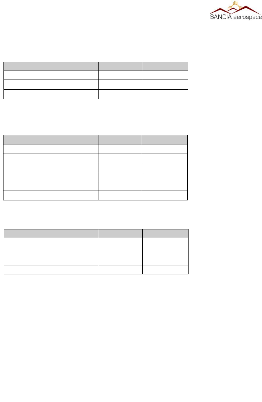
Table 1: Equipment under STC
Equipment covered by STC Equipment not covered by STC
SANDIA STX 360 Transponder/ UAT Antenna
SANDIA STX 360R GPS Antenna
WAAS GPS posion sources as shown in Table 6
Altude Encoders as shown in Table 7
Installaon kit, mechanical and Electrical – secon 3.2.1.1

__________________________________________________________________
1.5.1 System Funcons Panel Mount
The STX 360 panel mount unit performs the following functions:
•UAT ADS-B In and Out [XMT power 30W nom, RCV sensitivity -93dBm]
•Built in Mode C transponder [XMT power 200W nom, RCV sensitivity -74dBm]
•Built in Diplexer [single antenna installation]
•Display of traffic
•Display of METARs
•Single Entry for squawk code
•Built in Ethernet
•USB power - +5VDC @ 500mA max
•Automatic and Manual Brightness Control
•Display of aircraft power
•Selectable anonymous mode in VFR
•Built in emergency squawk codes
•Pass-thru TIS-B, FIS-B, ADS-B state and vector messages
•Tray Mounted
1.5.2 System Funcons Remote Mount
•UAT ADS-B In and Out [XMT power 30W nom, RCV sensitivity -93dBm]
•Built in Mode C transponder [XMT power 53.4dBm, RCV sensitivity -74dBm]
•Built in Diplexer [single antenna installation]
•SMA connector
•Built in Ethernet
•USB power - +5VDC @ 500mA max
•Pass-thru TIS-B, FIS-B, ADS-B state and vector messages
•Anonymous mode in VFR
•Built in emergency squawk codes
www.sandia.aero 306467-00 STX 360 Installaon Manual REV 1
Page 13
__________________________________________________________________
1.5.3 Unit Outer Dimensions
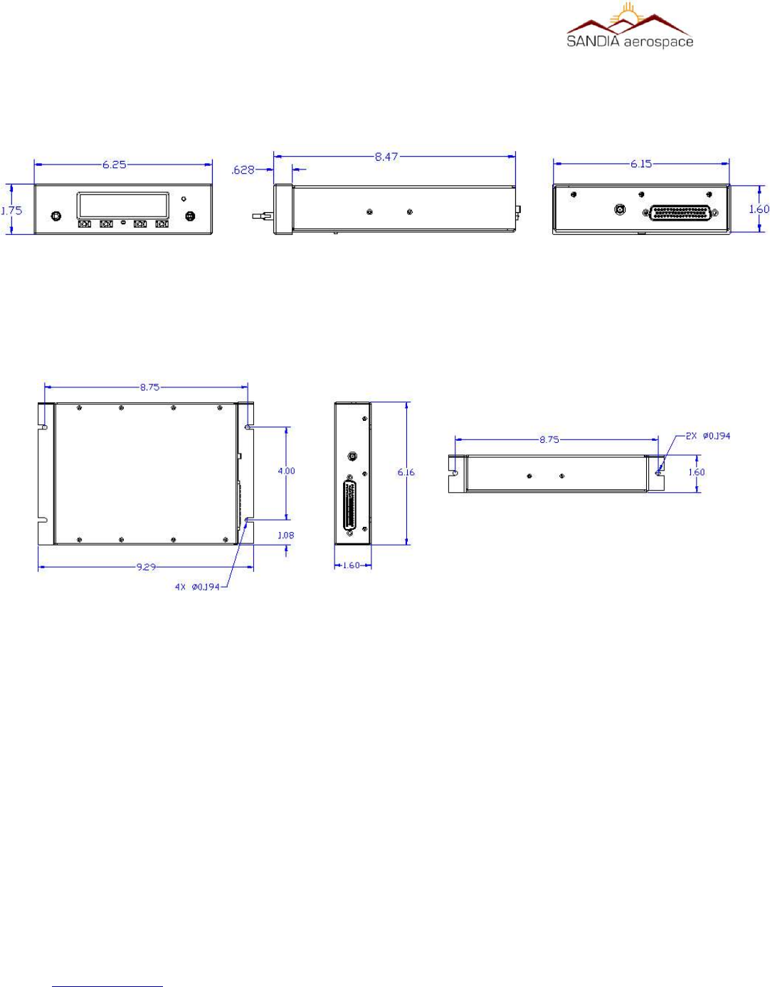
1.5.3.1 STX 360 Panel Mount
1.5.3.2 STX 360R Remote
1.6 Specificaons
1.6.1 Physical Characteriscs
1.6.1.1 STX 360 Panel Mount
Mounting……………………………………………..Refer to Figure 1: Physical dimensions of STX 360 panel mount
Bezel Dimensions …………………………………...1.75” H x 6.25”W x .628” L
Behind Panel Dimensions……………………………1.6” H x 6.15”W x 7.84” L
Weight……………………………………………….. 2.25 Lbs. (1.020kg)
Viewing Angle………………………………………..> 160°
Operating Temp………………………………………-40°C to +55°C
Power Input…………………………………………..11-32 VDC
www.sandia.aero 306467-00 STX 360 Installaon Manual REV 1
Page 14
Figure 1: Physical dimensions of STX 360 panel mount
Figure 2: Physical dimensions of STX 360R remote

__________________________________________________________________
Current……………………………………………….0.9A@11VDC and 0.32A@32VDC
1.2.1.1 STX 360R Remote Mount Unit
Overall Dimensions………………………………….1.6”H x 6.16W x 9.29” L
Weight……………………………………………….. 2.25 Lbs. (1.020kg)
Operating Temp………………………………………-40°C to +55°C
Power Input…………………………………………..11-32 VDC
Current………………………………………………..0.9A@11VDC and 0.32A@32VDC
1.2.2 Performance Characteriscs – STX 360 and STX 360R
1.3.2.1 MODE C Transponder
Power Out………………………………………………….200Watts Nominal
Transmitter Frequency……………………………………..1090 MHz
Receiver Frequency………………………………………..1030 MHz
Receviver Sensitivity………………………………………-74dBm Nominal at 90% reply rate
Modulaon……………………………………………………………...Pulse Posion – 15 long with each pulse 0.45uSec
long with 0.1uSec maximum rise me and 0.2 uSec fall me. The 15 pulses are 12 informaon pulses
spaced 1.45uSec between two framing pulses 20.3uSec apart.
Emission Designator………………………………………………...14M0M1D
1.3.2.2 Universal Access Transceiver
Power Out…………………….…………………………….40 Watts Maximum
Transmitter Frequency……….……………………………..978 MHz
Receiver Frequency………….……………………………..978 MHz
Receviver Sensitivity……………………………………….-93dBm Nominal at 90% reply rate
Tolerance…………………………………………………....+/- 20ppm
Data Rate…………………………………………………....1.04167 Mbps
Modulation…………………………………….…………….2FSK
Emission Designator…………………………………………1M30F1D
www.sandia.aero 306467-00 STX 360 Installaon Manual REV 1
Page 15

__________________________________________________________________
1.2.3 Operaonal Characterisics
1.2.3.1 STX 360 Panel Mount
Operaonal Voltage: 11 – 32Vdc
Current: All current readings are performed in Normal operaon (UAT and Mode C):
Aircra Power PRF Squawk Code Was Current
14Vdc 500 7777 16 1.14
14Vdc 500 1200 10 .73
Aircra Power PRF Squawk Code Was Current
28Vdc 500 7777 16 .55
28Vdc 500 1200 10 .36
Altude: -1000 to 18,000
1.2.3.2 STX 360R Remote Unit
Operaonal Voltage: 11 – 32Vdc
Current: All current readings are performed in Normal operaon (UAT and Mode C):
Aircra Power PRF Squawk Code Was Current
14Vdc 500 7777 16 1.14
14Vdc 500 1200 10 .73
Aircra Power PRF Squawk Code Was Current
28Vdc 500 7777 16 .55
28Vdc 500 1200 10 .36
Operang Temp: -20 deg C to +55 degC
Altude: -1000 to 18,000
www.sandia.aero 306467-00 STX 360 Installaon Manual REV 1
Page 16

__________________________________________________________________
1.2.4 Cerficaon
Transponder………………………………………………………..TSO-C74d - Class A
ADS-B (UAT)..……………………………………………………TSO-C154c - Class A1S
ADS-B (FIS-B)……………………………………………………TSO-C157b - Class 1
ADS-B (TIS-B).…………………………………………………...TSO-C195a - Class C1
Software……………………………………………………………DO-178B Level C
Environmental……………………………………………………...DO-160G (See qualification table)
STX 360 (A1C1)X]CAB(SM)XXXXXZBAB[BC][TT]M[A3B2]XXXX
STX 360R (A1C1)X]CAB(SM)XXXXXZBAB[BC][TT]M[A3B2]XXXX
FCC ID……………………………………………………………..YJL-DAGEDX
“The condions and test required for TSO approval of this arcle are minimum performance standards. It
is the responsibility of those desiring to install the arcle either on or within a specific type or class of
aircra to demonstrate that the aircra installaon condions are within the TSO standards. The arcle
may be installed only if installaon of the arcle is approved by the Administrator.”
www.sandia.aero 306467-00 STX 360 Installaon Manual REV 1
Page 17

__________________________________________________________________
Environmental Qualification Form for the STX 360 Sentinel
NOMENCLATURE: STX 360, Airbourne ADSB Equipment
TYPE/MODEL/PART No: STX 360 / 306XXX- [XX] & Electrical Install Kit P/N 306XXX
TSO NUMBER: C74d (transponder)
C154c (ADSB) - Class A1S
C157b ( FIS-B) - Class 1
C195a (ADSB) – Class C1
MANUFACTURE’S SPECIFICATION AND/OR OTHER APPLICABLE SPECIFICATION:
STX 360 INSTALL MANUAL, P/N 306467-00
QUALIFICATION TEST PLAN, STX 360 SENTINEL ADSB P/N 901XXX-QTP
MANUFACTURER: SANDIA AEROSPACE
ADDRESS: 3700 OSUNA RD NE, SUITE 711, ALBUQUERQUE, NM 87109
REVISION & CHANGE NUMBER OF DO-160: REV G DATED December 2010
DATE OF TESTS: 2016 STX 360 panel mount Environmental categories
Test Description DO-160G SEC-
TION
Conditions and Notes
Ground Survival and Operating Low Temperature 4.5.1 & 4.5.2 Category A1D1
Ground Survival and Operating High Temperature 4.5.3 & 4.5.4 Category A1D1
Altitude 4.6.1 Category A1D1
Decompression 4.6.2 Category A1D1
Overpressure 4.6.3 Category A1D1
Temperature Variation 5 Category B
Humidity 6.3 Category A
Operational Shock and Crash Safety 7 Category B
Sustained Crash Safety 7.3.3 Test Type 5
Vibration-standard 8.2.1.1 Category S – Curve B and M
Explosion 9N/A
Waterproof 10 N/A
Fluid Susceptibility 11 N/A
www.sandia.aero 306467-00 STX 360 Installaon Manual REV 1
Page 18

__________________________________________________________________
Sand and Dust 12 N/A
Fungus 13 N/A
Salt Spray 14 N/A
Magnetic Effect 15.3 Category Z
Power Input – Normal Operating Conditions 16.6.1.1 Category A
Power Input – Momentary Power Interruptions 16.6.1.3 Category A
Power Input – Normal Surge 16.6.1.4 Category A
Power Input – Engine Start Under Voltage 16.6.1.5 Category A
Power Input – Abnormal Operating conditions 16.6.2 Category A
Power Input – Momentary Under Voltage 16.6.2.3 Category A
Power Input – Abnormal Surge 16.6.2.4 Category A
Voltage Spike 17 Category A
Audio Frequency Susceptibility 18 Category Z
Induced Signal Susceptibility – Magnetic fields induced 19.3.1 Category ZC
Induced Signal Susceptibility – Electric fields induced 19.3.2 Category ZC
Induced Signal Susceptibility - Magnetic fields in cable 19.3.3 Category ZC
Induced Signal Susceptibility – Electric fields in cable 19.3.4 Category ZC
Induced Signal Susceptibility – Spikes induced 19.3.5 Category ZC
Radio Frequency Susceptibility Radiated
Radio Frequency Susceptibility Conducted
20
20
Category RR
Radio Frequency Emission - Radiated 21 Category H
Radio Frequency Emission - Conducted 21 Category H
Lightning – Cable Bundle 22 A3
Lightning – Pin Injection 22 B2
Lightning – Direct Effects 23 N/A
ICING 24 N/A
Electrostatic Discharge 25 N/A
www.sandia.aero 306467-00 STX 360 Installaon Manual REV 1
Page 19

__________________________________________________________________
Fire, Flammability 26 N/A
Environmental Qualification Form for the STX 360R Sentinel
NOMENCLATURE: STX 360, Airbourne ADSB Equipment
TYPE/MODEL/PART No: STX 360 / 306XXX- [XX] & Electrical Install Kit P/N 306XXX
TSO NUMBER: C74d (transponder)
C154c (ADSB) - Class A1H
C157b ( FIS-B) - Class 1
C195a (ADSB) – Class C1
MANUFACTURE’S SPECIFICATION AND/OR OTHER APPLICABLE SPECIFICATION:
STX 360 INSTALL MANUAL, P/N 306XXX-XX
QUALIFICATION TEST PLAN, STX 360 SENTINEL ADSB P/N 901XXX-QTP
MANUFACTURER: SANDIA AEROSPACE
ADDRESS: 3700 OSUNA RD NE, SUITE 711, ALBUQUERQUE, NM 87109
REVISION & CHANGE NUMBER OF DO-160: REV G DATED December 2010
DATE OF TESTS: 2016
Test Description DO-160G SECTION Conditions and Notes
Ground Survival and Operating Low Temperature 4.5.1 & 4.5.2 Category A1D1
Ground Survival and Operating High Temperature 4.5.3 & 4.5.4 Category A1D1
Altitude 4.6.1 Category A1D1
Decompression 4.6.2 Category A1D1
Overpressure 4.6.3 Category A1D1
Temperature Variation 5 Category B
Humidity 6.3 Category A
Operational Shock and Crash Safety 7 Category B
Sustained Crash Safety 7.3.3 Test Type 5
Vibration-standard 8.2.1.1 Category S – Curve B and M
Explosion 9N/A
www.sandia.aero 306467-00 STX 360 Installaon Manual REV 1
Page 20

__________________________________________________________________
Waterproof 10 N/A
Fluid Susceptibility 11 N/A
Sand and Dust 12 N/A
Fungus 13 N/A
Salt Spray 14 N/A
Magnetic Effect 15.3 Category Z
Power Input – Normal Operating Conditions 16.6.1.1 Category A
Power Input – Momentary Power Interruptions 16.6.1.3 Category A
Power Input – Normal Surge 16.6.1.4 Category A
Power Input – Engine Start Under Voltage 16.6.1.5 Category A
Power Input – Abnormal Operating conditions 16.6.2 Category A
Power Input – Momentary Under Voltage 16.6.2.3 Category A
Power Input – Abnormal Surge 16.6.2.4 Category A
Voltage Spike 17 Category A
Audio Frequency Susceptibility 18 Category Z
Induced Signal Susceptibility – Magnetic fields induced 19.3.1 Category ZC
Induced Signal Susceptibility – Electric fields induced 19.3.2 Category ZC
Induced Signal Susceptibility - Magnetic fields in cable 19.3.3 Category ZC
Induced Signal Susceptibility – Electric fields in cable 19.3.4 Category ZC
Induced Signal Susceptibility – Spikes induced 19.3.5 Category ZC
Radio Frequency Susceptibility Radiated
Radio Frequency Susceptibility Conducted
20
20
Category RR
Radio Frequency Emission - Radiated 21 Category H
Radio Frequency Emission - Conducted 21 Category H
Lightning – Cable Bundle 22 A3
Lightning – Pin Injection 22 B2
Lightning – Direct Effects 23 N/A
www.sandia.aero 306467-00 STX 360 Installaon Manual REV 1
Page 21

__________________________________________________________________
ICING 24 N/A
Electrostatic Discharge 25 N/A
Fire, Flammability 26 N/A
www.sandia.aero 306467-00 STX 360 Installaon Manual REV 1
Page 22

__________________________________________________________________
2 Installaon Consideraons
2.1 General
The STX 360 Sentinel is a UAT IN/OUT ADS-B unit with a built-in Mode A/C transponder. The STX 360 can
easily be installed in the same space as most existing panel mounted transponders, simplifying the installation. The
STX 360 has an internal diplexer that allows both the transponder and the UAT to share a single antenna. Because it
is a combination unit, there is a single point of entry for the squawk code which eliminates the possibility of
reporting two different codes. The STX 360 requires altitude input from an encoder, such as the Sandia SAE 5-35,
in RS 232 format as well as a position source from a WAAS GPS through a RS 232, or RS 422 interface.
The STX 360R is a remote version designed to be used with other navigation systems. SANDIA provides a Interface
Control Document to those that wish to interface with the STX 360R. The ICD can be obtained from SANDIA
Aerospace by contacting the factory at 505.341.2930. The STX 360R can be hard mounted in the aircraft. The STX
360R requires altitude input from an encoder, such as the Sandia SAE 5-35, in RS 232 format as well as a position
source from a WAAS GPS through a RS 232, or RS 422 interface.
2.2 Mounng Consideraons
2.2.1 STX 360 Panel Mount
The STX 360 is designed to be tray mounted in a standard cutout.
2.2.1.1 Oponal
2.2.2 STX 360R Remote Mount
The STX 360R is designed to be mounted behind aircraft panel, or under the seat or other remote locations where
panel space is available.
SECTION 3 Installaon Procedures
3.1 General
The STX 360 and STX 360R are supplied with one 50 pin Sub-D mating connector and clam shell. The Sub-D
connector use screws to secure the connector to the unit. Also supplied is a BMA connector for the panel mount
STX 360 unit and a SMA coax for the STX 360R for connecting the antenna coax. Recommended coax should be
RG400 or equivalent. It is important that proper installation techniques be observed in attaching wires and building
the antenna cable. See section 3.6.3 for proper assembly of antenna cable.
The STX 1360 and STX 360R must never be turned on without the antenna connected. FAILURE TO DO SO
COULD CAUSE DAMAGE TO THE TRANSMITTER.
www.sandia.aero 306467-00 STX 360 Installaon Manual REV 1
Page 23
__________________________________________________________________
3.2 Equipment Required
3.2.1 STX 360 Panel Mount
3.2.1.1 Supplied
The STX 360 Mechanical Installation kit (306481-00) comes with the following:
The STX 360 Electrical Installation kit (306462-00) comes with the following:
3.2.1.2 Required but not supplied
Coaxial cable will be required to connect to the STX 360 with the provided BMA Flange Mount RF
connector. RG 400U or equivalent is recommended. When using an equivalent coaxial cable, ensure the
diameter of the cable is equivalent for proper fit when installing the BMA Flange Mount RF connector.
Addionally hookup cable will be required to interface with STX 360 through the 50 pin D-sub connector.
3.2.1.3 Oponal
Optional accessories are not sold through SANDIA, however call the factory for advice on locating the following
options below:
www.sandia.aero 306467-00 STX 360 Installaon Manual REV 1
Page 24
Table 2: STX 360 Panel Mount supplied components
Descripon
QTY
Sandia P/N
STX 360 Panel Mount 1 306430-00
STX 360 Electrical Installaon Kit 1 306462-00
STX 360 Mechanical Installaon Kit 1 306481-00
Table 3: STX 360 Mechanical Installaon Kit
Descripon QTY Sandia P/N
STX 360 Tray 1 306438
Screw, 2-56, PHP, SS, 1/4” 3 305845-03
Screw, 4-40, PHP, SS, 1/4” 3 305042-03
Washer, Split Lock, SS #3 3 305179-02
Washer, Split Lock, SS #6 3 305179-04
Nut, Stn, Ptrn SS #2 3 305053-01
Table 4: STX 360 Electrical Installaon Kit
Descripon QTY Sandia P/N
Connector 50 pin Dsub 1 305065
Socket, Size 20 Crimp D Conn 51 205090-1
Backshell with cable clamp 1 306453
Conn, RF, BMA, Female, Flng Mnt 1 306364
__________________________________________________________________
•USB connector with circular panel mount for powering a device up to
500mA .
•Ethernet to WIFI adapter 3.2.2 STX 360R Remote Mount
3.2.2.1 Supplied
The STX 360R Electrical Installation kit (306462-10) comes with the following:
3.2.2.2 Required but not supplied
Coaxial cable will be required to connect to the STX 360 with the provided BMA Flange Mount RF connector. RG
400U or equivalent is recommended. When using an equivalent coaxial cable, ensure the diameter of the cable is
equivalent for proper fit when installing the SMA RF connector.
Additionally hookup cable will be required to interface with STX 360 through the 50 pin D-sub connector.
3.3.2.3 Oponal
Optional accessories are not sold through SANDIA, however call the factory for advice on locating the following
options below:
•Ethernet to WIFI adapter
3.3 Electrical
The STX 360 and STX 360R operate on 11-32Vdc. Power should be protected by a 3 amp fuse or circuit breaker.
Below in Table 7 is a summary of the STX 360 interfaces. Refer to section 3.7.2 for specifics on pin out
information.
www.sandia.aero 306467-00 STX 360 Installaon Manual REV 1
Page 25
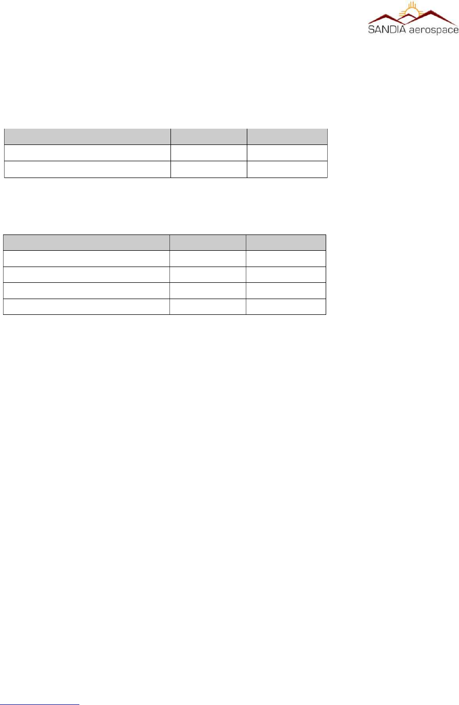
Table 5: STX 360R Remote supplied in box
Descripon QTY Sandia P/N
STX 360 Remote Mount 1 306431-00
STX 360 Electrical Installaon Kit 1 306462-10
Table 6: STX 360R Remote Electrical Installaon Kit
Descripon QTY Sandia P/N
Connector 50 pin Dsub 1 305065
Socket, Size 20 Crimp D Conn 51 205090-1
Backshell with cable clamp 1 306453
Connector, SMA, RG400, Crimp 1 306109
__________________________________________________________________
www.sandia.aero 306467-00 STX 360 Installaon Manual REV 1
Page 26
Table 7: STX 360 Electrical interfaces
Interface Type Number
RS232 TX/RX 6
RS422 TX/RX 2
ARINC 429 In 2
Ethernet (ADS-B) 1
Discrete Inputs 5
Discrete Outputs 6
5V power (USB) 1
Switch Power 11 – 33VDC out 1
RF port 1
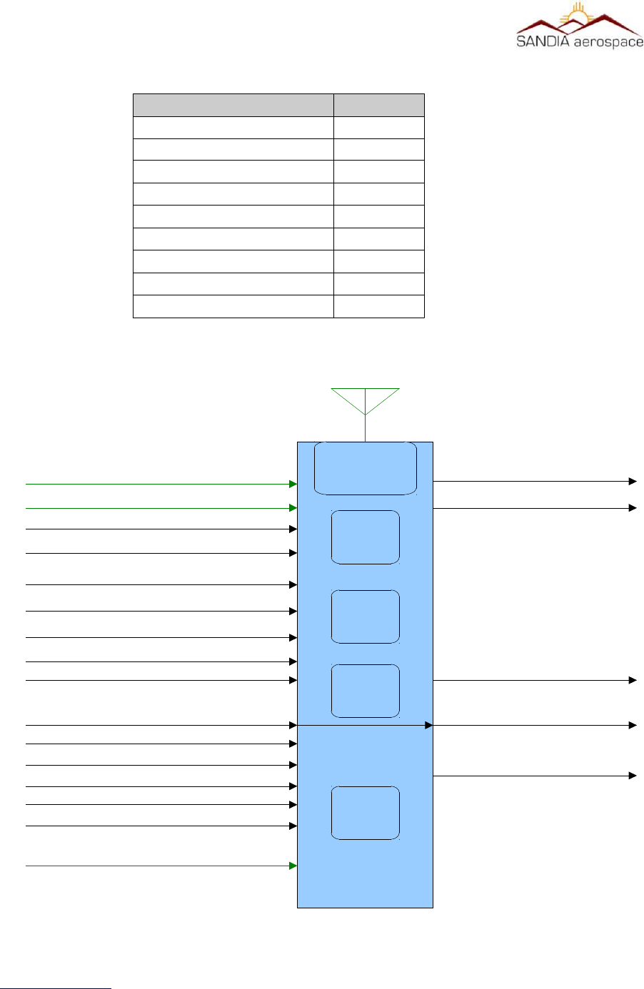
Figure 3: STX 360 system interface
STX 360
GPS_1 - RS232
Flight Control Unit - RS232
Autopilot Control Panel - RS232
Air Data Computer - RS232
Maintenance - RS232
Suppression – Discrete Input
Report/Display – RS232
On Ground - Discrete Input
Ident – Button/Discrete Input
4 Color Grayscale Display (256x64)
Radar Altimeter - RS232
Maintenance - RS232
GPS_1 Pulse Per Second – Discrete Input
GPS_2 - RS232
GPS_2 Pulse Per Second – Discrete Input
Report/Display – ETHERNET
3 Rotary Knobs – 6 Discrete Inputs
Emergency – Button
2 Knob Pushbuttons – 2 Discrete Inputs
FPGA
CPU
Diplexer
RF
Suppression – Discrete Output
Power
Supply
28 Volt Power and Aircraft Ground
__________________________________________________________________
WARNING: The STX 360 / STX 360R must NEVER be turned on without the antenna connected or a
proper aenuator aached to the antenna output connector. Failure to do so will result in the failure of
the transmier output device. This type failure is not covered by the manufacturer’s warranty
Installaon to be in accordance with FAA AC 43.13-1B
3.4 AIRCRAFT MOUNTING
3.4.1 STX 360
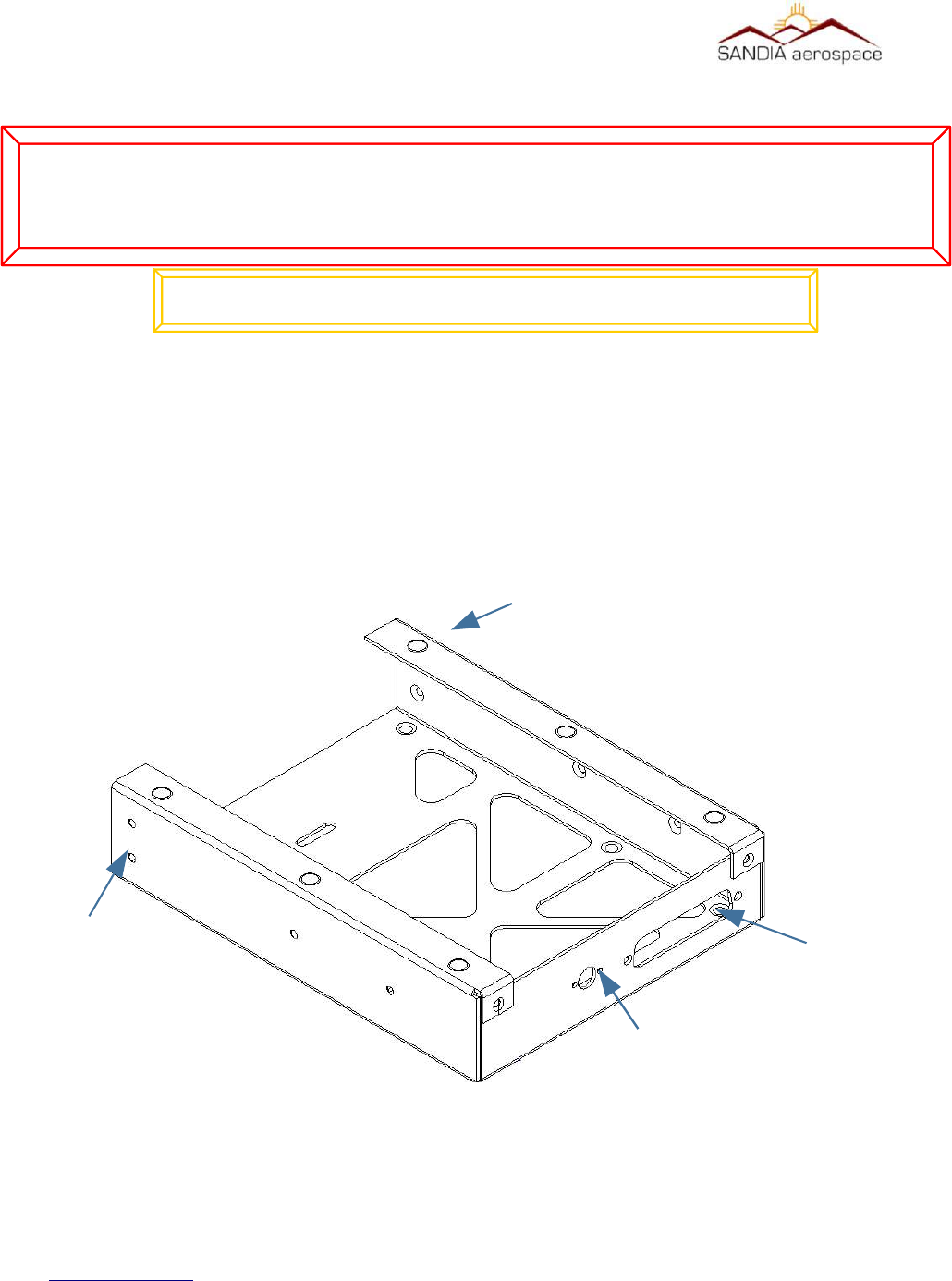
3.4.1.1 Mounng Tray
The STX 360 tray is mounted first into the aircraft panel using 2 shop fabricated L brackets. Hole locations are
provided to mount the L brackets to the tray.
Once the tray is secured in place, the STX 360 will not require any additional mechanical support. The panel cut out
is a standard “Mark” width and in many cases utilizes the existing cutout from the removal of a transponder. Allow
enough room behind the panel for the unit, connectors and harness.
For new panel installations where a cutout has not been performed before the panel cutout dimensions are shown
below:
www.sandia.aero 306467-00 STX 360 Installaon Manual REV 1
Page 27
Figure 4: STX 360 panel mount tray
L Bracket
L Bracket
BMA PNL MT
Cable assy
D-sub 50
Cable assy
__________________________________________________________________
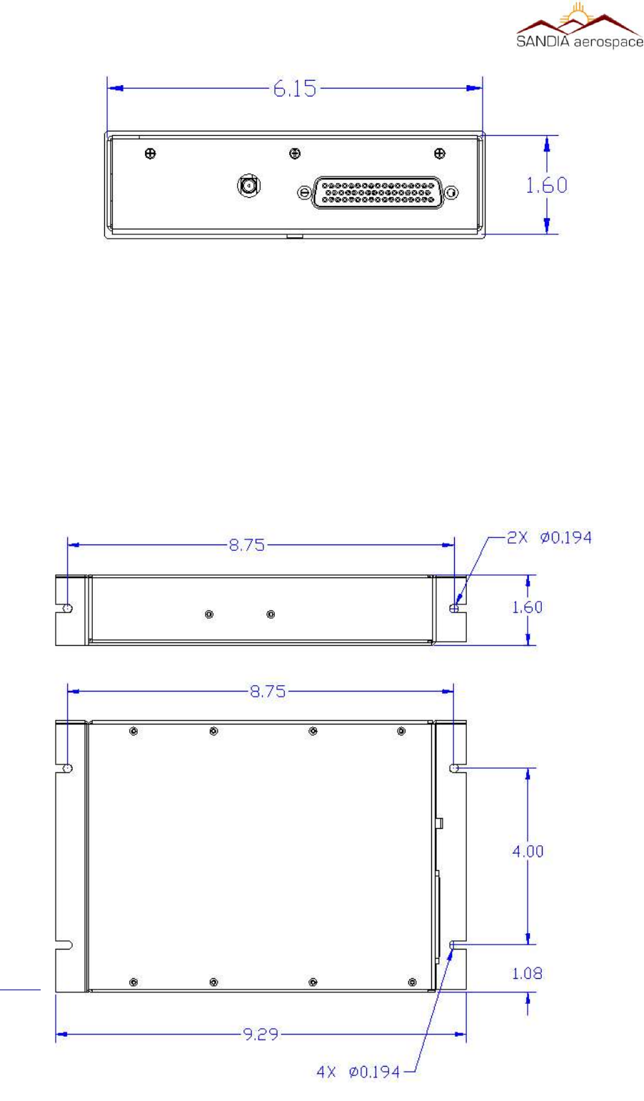
3.4.2 STX 360R
The STX 360R can be mounted either vertically or horizontally using the flanges on the outer case.
3.4.2.2 STX 360R Flange Mounng
The STX 360R can be hard mounted to the aircraft using the slotted flanges on the unit using either number 6 or
number 8 mounting screws. It can be mounted in either axis. When mounted on the narrow edge two screws are
used to fasten the unit. When on the wide edge, either three or four mounting screws are required. When mounting
the unit, ensure that enough clearance is allowed for the mating connectors.
www.sandia.aero 306467-00 STX 360 Installaon Manual REV 1
Page 28
Figure 5: STX 360 panel mount hole dimensions
Figure 6: STX 360R Remote physical dimensions

__________________________________________________________________
3.6 Electrical Connecon
The STX 360 and STX 360R are designed to operate on 11-32Vdc without any special wiring considerations. Power
should be supplied from aircraft power through a 2 amp fuse or circuit breaker to protect the Sentinel ADS-B unit.
The STX 360 and STX 360R also output unswitched aircraft power (J4 pin 4 – see section 3.7.1 for more details ) to
operate other avionics. If this output is used (a Maximum of 1 Amp), the fuse or breaker size should be adjusted to
accommodate the other system. Power and ground wires are 20 AWG. All other wires are 22 AWG unless otherwise
noted.
3.6.1 STX 360 Panel Mounted Unit
The minimum installation for an operable STX 360 is Aircraft Power, Aircraft Ground, Antenna, pressure altitude
from an altitude encoder and WAAS GPS position source. Aircraft power and ground are both found on J4 of the 50
pin D-sub connector. The STX 360 receives encoder altitude data in either RS 232 or ARINC 429. The STX 360
receives GPS position source through RS232 or RS422. The STX 360 has the ability to have two positions sources
connected through either protocol as a primary or secondary. A radar altimeter can also be connected through a
configurable high/low ARINC429 interface. ADS-B information such as TIS-B and FIS-B can be sent through
ethernet or a configurable RS232 interface. An additional RS232 [38400-N-8-1] can be used for a flight control unit.
An additional RS232 [115200-N-8-1] is used for remote operation or maintenance port. See table 1 for all
connection details on D-sub 50 (J4).
3.6.2 STX 360R Remote Mounted Unit
The minimum installation for an operable STX 360R is Aircraft Power, Aircraft Ground, Antenna, pressure altitude
from an altitude encoder and WAAS GPS position source. Aircraft power and ground are both found on J4 of the 50
pin D-sub connector. The STX 360 receives encoder altitude data in either RS 232 or ARINC 429. The STX 360
receives GPS position source through RS232 or RS422. The STX 360 has the ability to have two positions sources
connected through either protocol as a primary or secondary. A radar altimeter can also be connected through a
configurable high/low ARINC429 interface. ADS-B information such as TIS-B and FIS-B can be sent through
ethernet or a configurable RS232 interface. An additional RS232 [38400-N-8-1] can be used for a flight control unit.
An additional RS232 [115200-N-8-1] is used for remote operation or maintenance port. See table 1 for all
connection details on D-sub 50 (J4).
3.6.3 Antenna Connector
3.6.3.1 STX 360 Panel Mounted Unit
The STX 360 panel mount ADS-B antenna (installer supplied) should be mounted vertically on the bottom of the
aircraft. The antenna requires the use of a ground plane that should have a minimum radius of approximately 4”. The
STX 360 uses a BMA Panel mount RF connector (supplied). Instructions for assembling the BMA connector are
shown below and a graphical stripping dimensions are shown in Figure 3-6.3.1 .
The BMA panel mount connector is a rear mount floating connector that utilizes RG 400 or equivalent coaxial cable.
Figure 3.6.3.1 shows how to to prepare the coaxial cable.
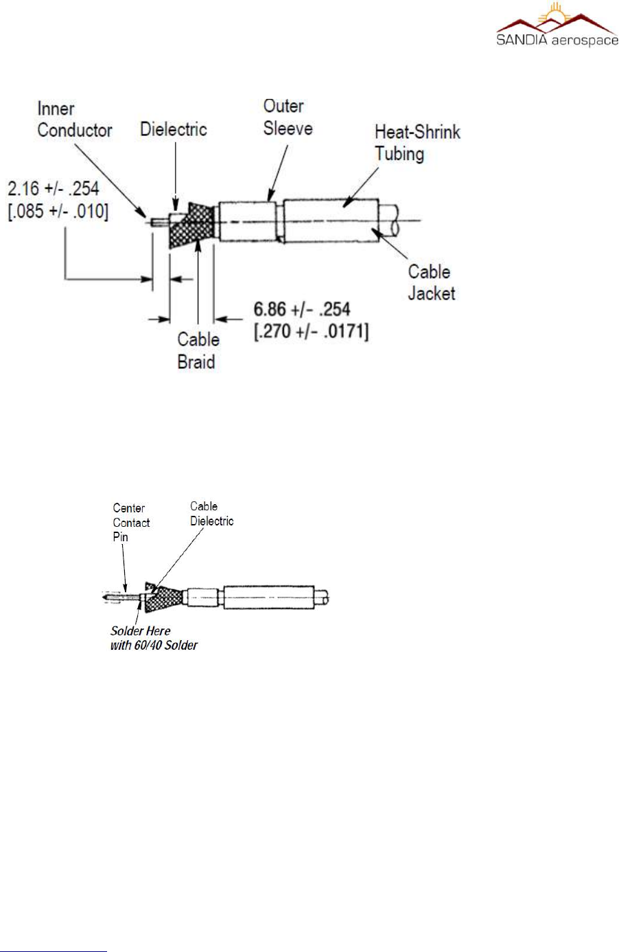
1. Place the provided heat-shrink tubing and outer sleeve on the cable
2. Remove approximately 1” of the cable jacket
3. Strip the cable braid to length as shown
4. Strip the cable with the inner conductor length as shown.
5. Flare the cable braid from the dielectric
www.sandia.aero 306467-00 STX 360 Installaon Manual REV 1
Page 29
__________________________________________________________________
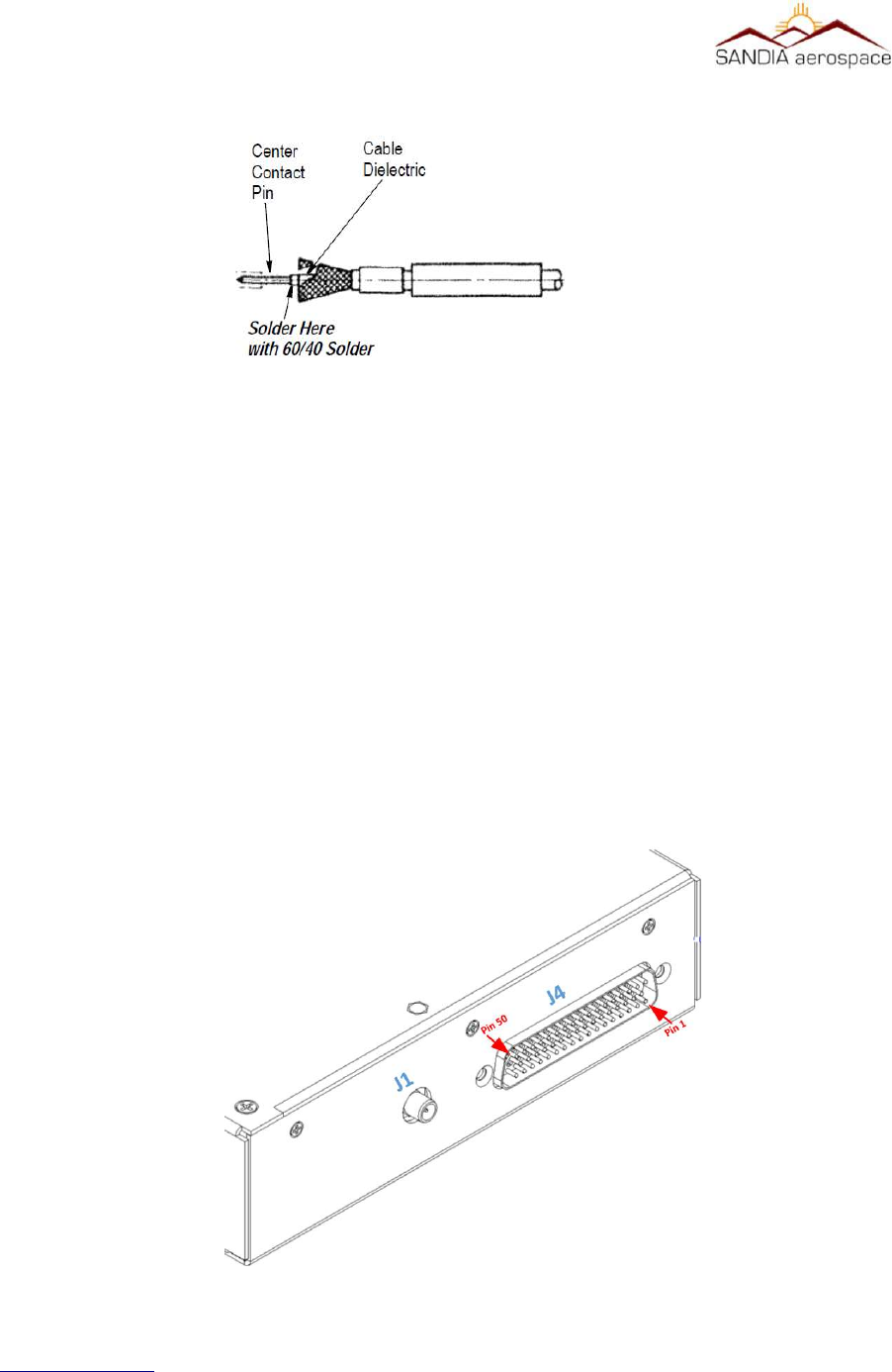
6. Tin the inner conductor of the cable
7. Push the center contact over the inner conductor of the cable and push firmly against cable dielectric while
heating the pin with a soldering iron.
8. Insert the cable into the BMA connector and seat firmly.
9. Slide the outer sleeve over the flared portion of the cable braid
10. Hold the assembly securely and bring the outer sleeve over the cable braid and crimp in place.
11. Slide the heat shrink tubing over the cable and housing subassembly.
12. Apply heat to shrink tubing
www.sandia.aero 306467-00 STX 360 Installaon Manual REV 1
Page 30
Figure 8: BMA center pin and final assembly on RG 400 or equivalent coax
Figure 7: RG 400 coax or equivalent preparaon for BMA Flange Mnt connector
__________________________________________________________________
3.6.3.2 STX 360R Remote Mounted Unit
The Sentinel ADS-B antenna (installer supplied) should be mounted vertically on the bottom of the aircraft. The
antenna requires the use of a ground plane that should have a radius of approximately 4”. The STX 360R uses a
SMA connector (supplied). Instruction for assembling the SMA connector are shown in Figure 3-6.3.2. A BNC to
SMA adapter can also be use without any measurable degradation of Transponder and UAT transceiver performance.
This adapter can be obtained from your avionics parts supplier.
The SMA panel mount connector is a rear mount floating connector that utilizes RG 400 or equivalent coaxial cable.
Figure 3.6.3.1 shows how to to prepare the coaxial cable.
1. Place the provided heat-shrink tubing and outer sleeve on the cable
2. Remove approximately 1” of the cable jacket
3. Strip the cable braid to length as shown
4. Strip the cable with the inner conductor length as shown.
5. Flare the cable braid from the dielectric
7. Tin the inner conductor of the cable
8. Push the center contact over the inner conductor of the cable and push firmly against cable dielectric while
heating the pin with a soldering iron.
www.sandia.aero 306467-00 STX 360 Installaon Manual REV 1
Page 31
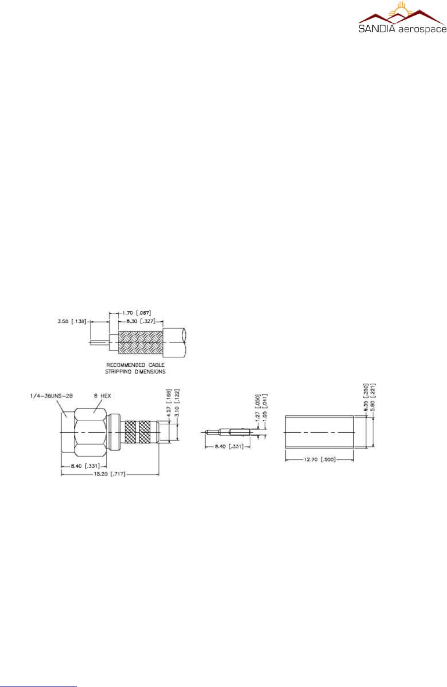
Figure 9: RG 400 coax or equivalent preparaon for SMA connector
__________________________________________________________________
9. Insert the cable into the SMA connector and seat firmly.
10. Slide the outer sleeve over the flared portion of the cable braid
11. Hold the assembly securely and bring the outer sleeve over the cable braid and crimp in place.
12. Slide the heat shrink tubing over the cable and housing subassembly.
13. Apply heat to shrink tubing
3.7 Connector Pin Out
3.7.2 STX 360 Panel Mounted Unit
www.sandia.aero 306467-00 STX 360 Installaon Manual REV 1
Page 32
Figure 10: SMA center pin and final assembly on RG 400 or equvalent coax
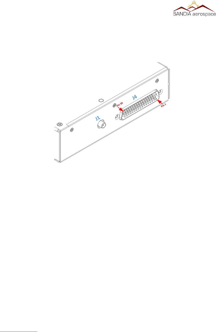
Figure 11: STX 360 panel mount with connecons shown for installaon

__________________________________________________________________
Located on the back of the STX 360 panel mount IN/OUT ADS-B unit is a 50 pin D-sub connector (J4) and a BMA
RF connector (J1). From the bottom right is pin 1 and top left is pin 50 as shown in the figure above. A 50 pin D-
sub female connector with crimp insertion pins in provided in the STX 360 panel mount installation kit (306462-10).
Table 9 on the next page describes each pin of the 50 pin D-sub connector (J4).
Follow instructions in 3.6.3.1 for interfacing and preparation of coax with J1 (BMA RF connector).
Description Pinout Protocol Format
Aircraft Power 11- 33VDC 1
Aircraft GND 2
Aircrft Power 11 - 33VDC 3
Switch Power 11 - 33VDC 4 OUTPUT
Maintenence / Remote 5 RS232:RXA
6 RS232:TXA
Altitude Encoder 7 RS232:RXB
8 RS232:TXB
USB Power 9 USB Power
10 USB Ground
FAULT (open collector) 11 Open/Closed switch Sinks
up to 500mA to drive an
LED/Lamp annunuciator
Open – UAT is operational
Close – UAT is failed
Pulse Per Second Out 12 RS-422 Level Output Pass through of first GPS or sec-
ond GPS depending on usage
Suppression 13 28V/GND (In/Out) High – Other equipment should
not transmit
Low – Other equipment may
transmit
Remote ON/OFF 14 Remote ON/OFF Open = ??
Ground = Holding it low for 3
www.sandia.aero 306467-00 STX 360 Installaon Manual REV 1
Page 33

__________________________________________________________________
Description Pinout Protocol Format
sec, turns the unit off
Flight Control Unit (FCU) 15 RS232:RXC <Config>-N-8-1
16 RS232:TXC <Config>-N-8-1
17 USB- Not available
GPS0 18 RS232:RXD <Config>-N-8-1
19 RS232:TXD <Config>-N-8-1
GPS1 – PPS 20 RS422B_RXA Pulse per Second for GPS1
21 RS422B_RXB Pulse per Second for GPS1
22 GND
GPS1 23 RS232:RXE <Config>-N-8-1
24 RS232:TXE <Config>-N-8-1
25 NC
26 GND
27 NC
ADS-B 28 Ethernet:LAN-TD+ 10/100 Mbit
29 Ethernet:LAN-TD- 10/100 Mbit
30 Ethernet:LAN-RD+ 10/100 Mbit
31 Ethernet:LAN-RD- 10/100 Mbit
GPS0-PPS 32 RS422A_RXA Pulse per Second for GPS0
33 RS422A_RXB Pulse per Second for GPS0
34 GND
35 RS232:RXF 115200-N-8-1
www.sandia.aero 306467-00 STX 360 Installaon Manual REV 1
Page 34

__________________________________________________________________
Description Pinout Protocol Format
36 RS232:TXF 115200-N-8-1
On 2nd NAV 37 Open/Closed switch Open – First GPS is being used.
Close – Second GPS is being used
Radar Altimeter 38 ARINC 429: RX A <Configurable High/Low>
39 ARINC 429: RX B <Configurable High/Low>
No Position 40 Open/Closed switch, Sinks
up to 500mA to drive a
LED/Lamp annunciator
Open – Position Available
Close – Position from GPS source
not available
Traffic 41 Open/Closed switch Open – No Traffic in vicinity
Close – Traffic in the vicinity
42 GND
43 ARINC 429: RX A <Configurable High/Low>
44 ARINC 429: RX B <Configurable High/Low>
Ext_Ident 45 Open/Ground Open = Ident not requested
Ground = Ident requested
46 USB+ Not available
Press Inibit 47 Open/Ground Reserved
Use 2nd NAV 48 Open/Ground Reserved
Air/Ground Discrete 49 Open/Ground Open = On Ground
Ground = In Air
Anonymous 50 Open/Ground Open = Anonymous not requested
Ground = Anonymous requested
www.sandia.aero 306467-00 STX 360 Installaon Manual REV 1
Page 35
__________________________________________________________________
3.7.3 STX 360 Remote Mounted Unit
Located on the back of the STX 360R remote IN/OUT ADS-B unit is a 50 pin D-sub connector (J4) and a SMA RF
connector (J1). From the bottom right is pin 1 and top left is pin 50 as shown in the figure above. A 50 pin D-sub
female connector with crimp insertion pins in provided in the STX 360R remote mount installation kit (306462-10).
Table 9 on the previous page describes each pin of the 50 pin D-sub connector (J4).
Follow instructions in 3.6.3.2 for interfacing and preparation of coax with J1 (SMA RF connector).
3.8 Calibraon Procedures - STX 360 Panel Mount Unit
No calibration necessary. The STX 360 is ready to be used once the minimum connections performed. This
includes Aircraft Power, Aircraft Ground, Antenna, pressure altitude from an altitude encoder and WAAS GPS
position source.
3.9 Installaon Configuraon - STX 360 Panel Mount
The STX 360 is to be used with a GPS position source and a pressure altitude source. In most cases the GPS and
Encoder are items many pilots have on the aircraft and intended to be used with the STX 360. Below is a system
block diagram of the STX 360 with the minimum connections:
www.sandia.aero 306467-00 STX 360 Installaon Manual REV 1
Page 36
Figure 12: STX 360R Remote connecons shown for installaon
__________________________________________________________________
www.sandia.aero 306467-00 STX 360 Installaon Manual REV 1
Page 37
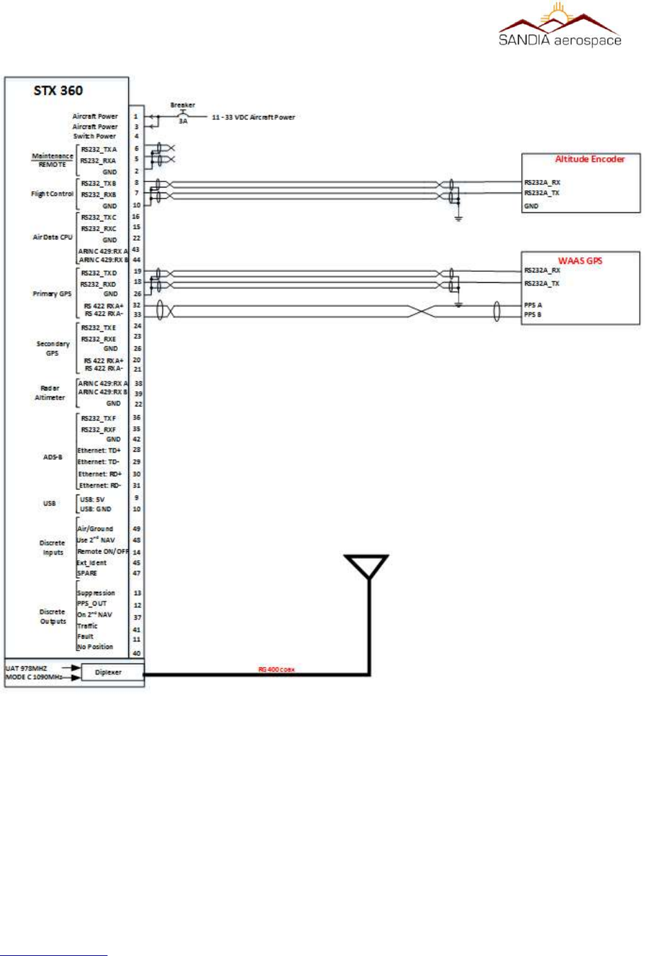
Figure 13: System block diagram of STX360 with minimum external interfaces
__________________________________________________________________
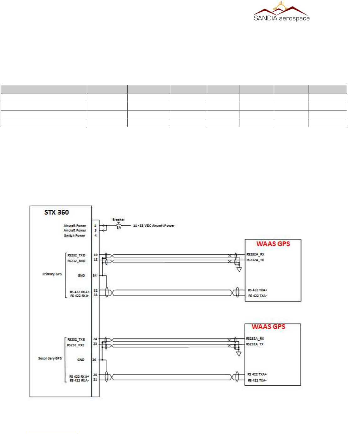
3.9.1 WAAS GPS posion source
The STX 360 SENTINEL allows for a primary and secondary GPS position input. This position input can be in
either a RS232 or RS422 format. The RS232 is configurable on the STX 360 which allows easy transition to any
WAAS position source with the RS232 or RS422 format. A list of the following position sources can be used. This
list is always growing and therefore if position source is not listed, please contact the factory for details of inclusion.
www.sandia.aero 306467-00 STX 360 Installaon Manual REV 1
Page 38
Table 8: WAAS Posion source manufacturers with compable format
Funcon GARMIN Avidyne Free Flight GRT MGL DYON Advance Flight
WAAS GPS 430W IFD440 1201 Hxr
530W IFD540
GNS 480
Figure 14: STX 360 WAAS GPS connecons for GPS0 and GPS1
__________________________________________________________________
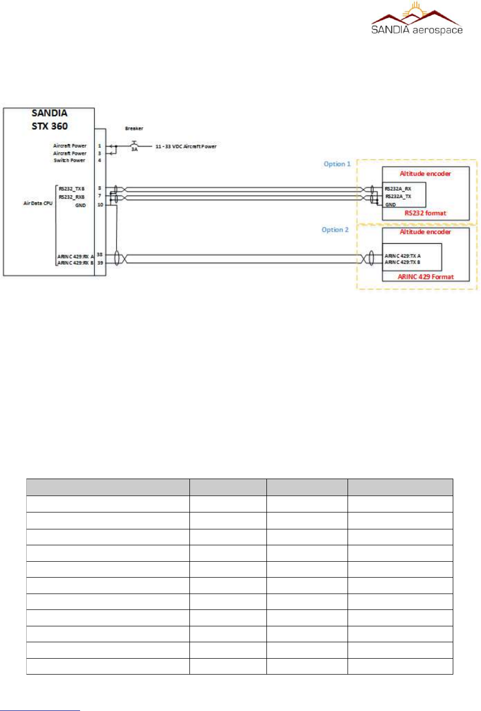
3.9.2 Altude Encoder
Any encoders that have a RS232 or ARINC 429 communication format can be used to interface with the STX 360.
The STX 360 RS232 baud rate is configurable so that any altitude encoder with a RS232 interface can be used.
Additionally the ARINC 429 is configurable for high or low data rates so that any altitude encoder with a ARINC
429 interface can be used.
A SANDIA SAE-35 Altitude encoder is recommended, however an existing encoder used from a previous
installation can be used with the STX 360 through RS232 or ARINC 429 inteface. Please refer to table 9 for exact
pin out information. Below is a list of Sandia Aerospace encoders that can be used as well:
www.sandia.aero 306467-00 STX 360 Installaon Manual REV 1
Page 39
Table 9: Sandia Aerospace Altude Encoders
Funcon Sandia Aero Cofiguraon Notes
Encoder SAI 340 57600, 8 1 N Atude indicator
SAC 7-35 1200, 9600, 19200 or 38400 8 1 N Air data computer
SAE5-35 9600, 8 1 N Altude encoder
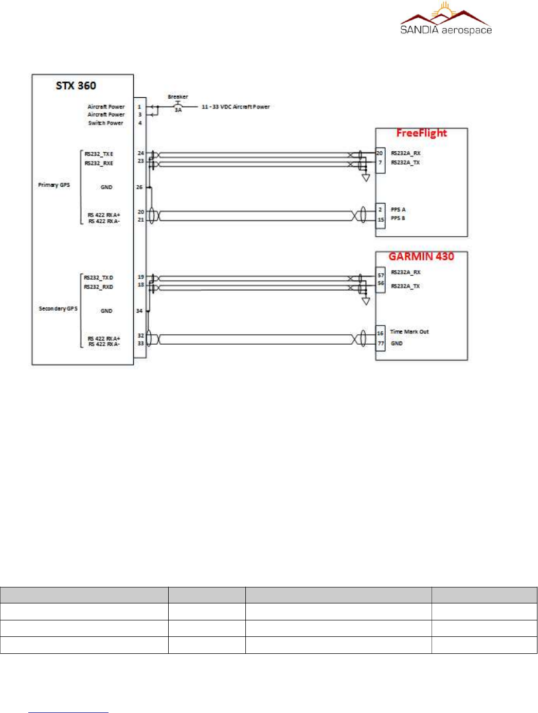
Figure 15: GARMIN 430 as GPS0 and FreeFlight 1201 as GPS1
__________________________________________________________________
Below is a electrical block diagram showing connections to a RS 232 and ARINC 429
interface altitude encdoder. Please refer to table 9 for all pinouts of the STX 360.
3.9.3 External Display for ADS-B informaon
An Android or IPAD can be used to display FIS-B weather, ADS-B traffic informaon, GPS posion and
atude informaon through a setup “hotspot” in the aircra cockpit. Below is a table of some of the
applicaons that are currently supported. If a parcular applicaon is not shown, please contact the
factory for support informaon. Support on most soware suites on IPAD/Android for displaying weather
(FIS-B) and Traffiic (TIS-B), through a common ethernet to WIFI adapter. However in some cases
customers may want to display weather and traffic on their EFIS. ADS-B formated data will be sent
through a configurable RS232 on the STX 360 to a EFIS with this protocol.
www.sandia.aero 306467-00 STX 360 Installaon Manual REV 1
Page 40
Table 10: ADS-B traffic and weather through Android/IPAD applicaons
Soware Package IPAD Android Notes
ForeFlight
WingX Pro X X
FlyQ EFB X
AeroWeather
iFlightPlanner
AirWX Aviaon Weather
FP Legacy
FltPlan Go
FlightView
SkewTLogPro
eKneeBoard
Figure 16: STX 360 Altude connecons through a RS 232 or ARINC 429 interface
__________________________________________________________________
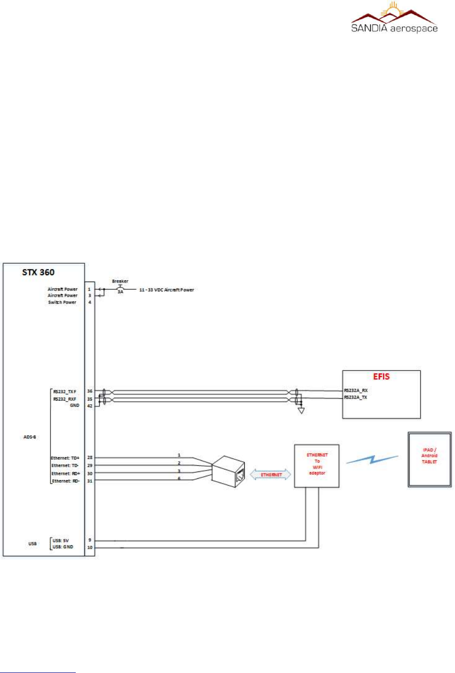
3.9.3.1 Ethernet to WIFI adaptor
An ethernet to wifi adapter can be used to create a “hotspot” within the cockpit. The adapter is connected to the
STX 360 through a RJ45 connector and using the wiring pin information in table 9. Once a WIFI hotspot is created,
a tablet of choice can be connected and utilize the ADS-B features with your flight software of choice as shown in
the table above. Below is a system block detailing connections on STX 360 for connecting to a EFIS on the RS 232
port and interfacing Ethernet to an Ethernet to WIFI adapter.
3.9.3.2 EFIS support
For an EFIS that is not supported through RS232 format, such as weather (FIS-B) and traffic (TIS-B), can
be displayed on most EFIS through the ARINC429 interface. This will require a RS232 to ARINC429
converter. Using a Sandia Aerospace RS232 to ARINC429 converter or equivalent will enable ADS-B
informaon to be displayed.
www.sandia.aero 306467-00 STX 360 Installaon Manual REV 1
Page 41
Figure 17: STX 360 ADS-B display suport through RS 232 or Ethernet.
__________________________________________________________________
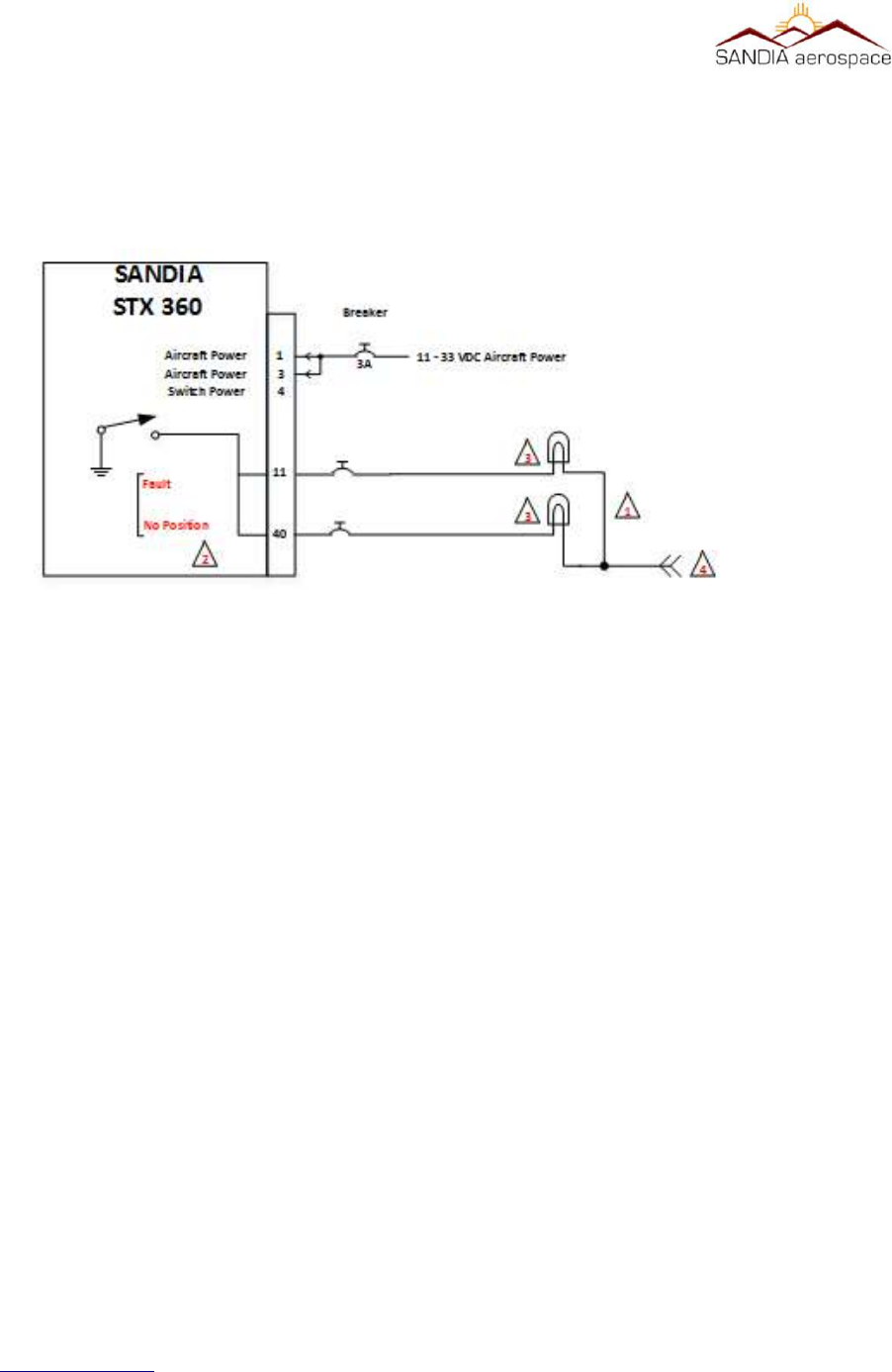
3.9.4 Annuciator connecons
The Annunciator circuit supplies a ground. Do not connect voltage directly to this input as it may cause
damage to internal circuitry. The annunciator light is required when no display is used and alerts the
pilot when a fault or posion source has been lost.
1. All wires should be a minimum of 22 AWG.
2. ADS-B annunciation controls necessary for installations without a display.
3. Use MS25041-8 light with [28VDC dimmer] MS25237-327 lamp or [14VDC dimmer] MS25237-330
lamp.
4. Lamp voltage from annunciator dimmer circuit
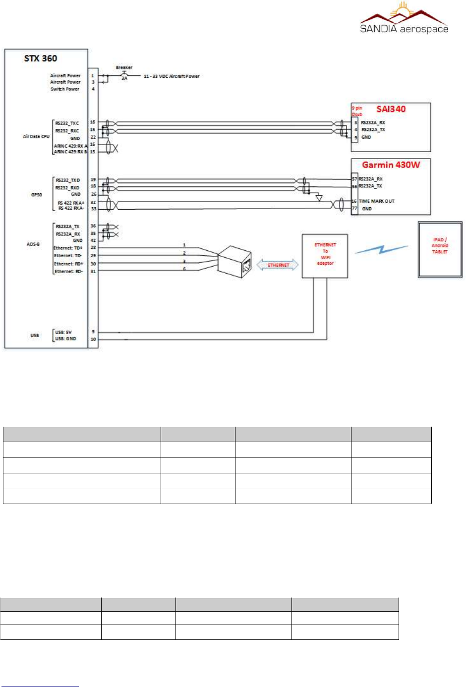
3.9.5 Typical installaon
Below is a typically installation the includes the STX 360, SAI 340 attitude indicator (Encoder) , WAAS position
source and the use of Ipad/Android tablet to display the ADS-B data using an application of choice.
3.9.5.1 Ethernet to WIFI
Ethernet connection on the STX 360 may be used to interface directly to a device or through a Ethernet to WIFI
adapter. Below are the necessary connections to interface the STX 360 to a CAT5 patch cable. Above in figure 19
is an example of wiring an CAT5 cable and below is a table showing STX 360 pin number with a CAT5 patch cable.
www.sandia.aero 306467-00 STX 360 Installaon Manual REV 1
Page 42
Figure 18: Annunciaor connecons for STX 360
__________________________________________________________________
3.9.5.2 USB Power
The STX 360 provides 500mA of USB power that is intended for powering a Ethernet to WIFI adapter,
however it can be used to power other devices of choice. An example of USB power is shown in figure
19. Below is a table showing typical power connecons:
www.sandia.aero 306467-00 STX 360 Installaon Manual REV 1
Page 43
Connecon STX 360 pin # CAT5 cable color CAT5 pin #
Ethernet:LAN-TD+ 28 Orange / White 1
Ethernet:LAN-TD- 29 Orange 2
Ethernet:LAN-RD+ 30 Green / White 3
Ethernet:LAN-RD- 31 Green 6
Figure 19: Installaon of STX 360 with WAAS posion source, encoder and oponal output to table through WIFI
Connecon
STX 360 pin #
USB cable
DC power plug
USB+
9
Red cable / Posive Red cable / Posive
USB-
10
Black cable / negave Black cable / negave
__________________________________________________________________
3.10 Antenna Consideraons
The RF section is very important as to ensuring termination of the STX360 to the type of coax cable type used to
considerations of mounting the antenna.
3.10.1 STX 360 terminaon
The STX360 antenna output should always be terminated prior to turning on the unit. Testing of the unit prior to
installation should have a 50 ohm load terminated on STX360. Prior to powering STX360 in aircraft, ensure that all
coaxial cable is routed and terminated to the tray (STX360) or terminated directly to unit (STX360R) and the other
end of the coaxial cable terminated to an aircraft transponder antenna. For coaxial cable and antenna considerations,
please see sub-sections below for specifics.
3.10.2 Coaxial selecon
When routing the antenna cable, sharp bends and routing near motors and generators should be avoided. The
antenna cable should be kept as short as possible. The length of coaxial should be < 1.5 dB of insertion loss (S21).
RG 400U or equivalent is the recommended coax to use for the antenna cable.
Note: coaxial types above is for reference only to emphasize cable loss by type. Pleas refer to manufacturers data
sheet to get exact insertion loss per foot information.
3.10.2 STX360 antenna
The typical antenna used is a monopole that adheres to the following specifications:
•50 ohm impedance
•VSWR ≤ 1.7:1 for UAT (978MHz) and VSWR ≤ 1.5:1 for ATCRBS (1090MHz)
•TSO-C74 / TSO-C66 / TSO-C112 antennas meeting VSWR specification.
www.sandia.aero 306467-00 STX 360 Installaon Manual REV 1
Page 44
Table 11: STX360 coaxial cable examples
Coaxial Type
RG-400 18.5 8.5 1.57dB
RG-393 9.2 17 1.564dB
RG-304 11.1 14 1.554dB
Inseron Loss
(dB/100)
Maximum
Length
Inseron
Loss (S21)

__________________________________________________________________
Note: antennas listed in table 12 above are not a complete list but an example of antennas that meet the VSWR
specification.
3.10.2.1 Antenna locaon
The antenna should be at least 3 feet away from the STX360
3.10.2.2 Antenna Installaon
4.1 MODE C funconality
www.sandia.aero 306467-00 STX 360 Installaon Manual REV 1
Page 45
Table 12: STX 360 antennas
Manufacturer Type MFN P/N Connector Impedance Polarization Frequency VSWR
COMANT DME/Trans ponder CI-105 BNC 50 Vertical Open circuit
COMANT DME/Trans ponder CI -105-16 BNC 50 Vertical Open circuit
COMANT DME/Trans ponder CI -105-6 BNC 50 Vertical Open circuit
COMANT DME/Trans ponder CI -105-3 BNC 50 Vertical Open circuit
COMANT DME/Trans ponder CI -105-9 BNC 50 Vertical Open circuit
COMANT DME/Trans ponder CI110-40 C 50 Vertical 1.5:1 960 to 1220 MHz Open circuit
COMANT DME/Trans ponder CI -110-60-30 C 50 Vertical 1.5:1 960 to 1220 MHz Open circuit
RAMI DME/Transponder AV74-1 BNC 50 Vertical 1.5:1 960 to 1220 MHz Open circuit
RAMI Transponder AV-22 BNC 50 1.3:1 Max
DC
impedance
960 -
1220MHz
1.5:1 960 to 1220 MHz
1.3:1 1030 to 1090 MHz
960 -
1220MHz
1.5:1 960 to 1220 MHz
1.3:1 1030 to 1090 MHz
960 -
1220MHz
1.5:1 960 to 1220 MHz
1.3:1 1030 to 1090 MHz
960 -
1220MHz
1.5:1 960 to 1220 MHz
1.3:1 1030 to 1090 MHz
960 -
1220MHz
1.5:1 960 to 1220 MHz
1.3:1 1030 to 1090 MHz
960 -
1220MHz
960 -
1220MHz
960 -
1220MHz
1030-
1090MHz
__________________________________________________________________
4.1.1 RS 232 BAUD Rate Selecon
The STX 360 RS 232 baud rate is configurable to work with any altude encoders baud rate. The factory
default seng is 9600 baud
4.1.2 MAX REPLY RATE
TSO requires a replay rate of 500 PRF to 1200 PRF. The factory default for the replay rate is 1200 PRF and this is
the recommended setting. In some instances where the STX 360 is operating on a battery the operator may wish this
setting to be lower than the maximum of 1200 in order to conserve battery power. 1. Rotate the Data knob to select
the MAX REPLY RATE page 2. Press the Enter pushbutton. The brackets will extinguish and the Reply Rate will
begin blinking. 3. Rotate the Data knob counter clockwise to decrease the replay rate (a minimum of 500 PRF) and
clockwise to increase the reply rate (a maximum of 1200 PRF)
4.1.3 Exit Installer Set Up Mode
To exit the installer set up mode, Press the Mode pushbutton twice.
4.2 USER SET UP MODE
4.2.1 Altude Unit
This changes the altitude display to the pilot between feet and meters. All altitude functions will be set to the
selected unit. 1. Rotate the Select knob counter clockwise to select Meters display and clockwise to select Feet
display.
www.sandia.aero 306467-00 STX 360 Installaon Manual REV 1
Page 46
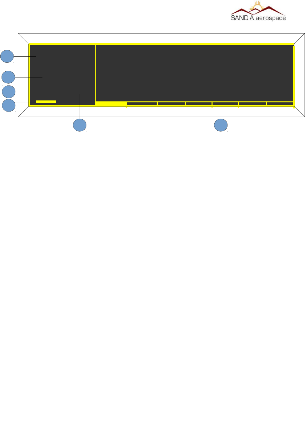
Figure 20: STX 360 display with Transponder informaon
MSGALT
FL220
1200
1
2
3
4
5
1 – Squawk Code
2 – Flight Level
3 – Transponder Mode
4 – Reply Light Blinker
5 – Message Indicator
6 – Information Pages with scroll bar
6
(From Altude input – non baro corrected)

__________________________________________________________________
4.2.2 AUTO MODE C ALT
The STX 360 can be set to automatically select Mode C either at turn on or at a pre specified altitude after take off.
The altitude after take off is the differential altitude from where the aircraft was tuned on as sensed by the external
encoder. This function can also be turned off, in which case it will turn on and stay in the SBY Mode until the pilot
selects an alternative mode.
1. Rotate the Data knob until the Auto Mode C Alt page is selected.
2. Press the Enter pushbutton. The brackets will extinguish and the data will blink.
3. Rotate the Data knob to select the differential altitude at which you wish the Mode C to be automatically selected.
Note that if you select 0 feet, Mode C will be selected at unit turn on.
4. Press the Enter pushbutton to select the EFT Altitude.
4.2.3 MIN BRIGHTNESS
The STX 360 uses a photo cell to sense the ambient light conditions and automatically adjust the brightness of the
display. This page allow the pilot to set the minimum brightness of the display to match other panel displays or his
preference. Note that the maximum brightness is preset at the factory and not adjustable.
1. Rotate the Data knob to display the MIN Brightness page.
2. Press the Enter pushbutton. The brackets will extinguish and the display will show the level of the minimum
brightness selected.
3. Rotate the Data knob clockwise to increase the minimum brightness and counter clockwise to decrease the
minimum brightness to the desired level.
4. Press the Enter pushbutton.
4.2.4 DEFAULT VFR CODE
The factory default VFR code is set to 1200, the normal US VFR code. The pilot can change the VFR code to the
one used in his local area.
1. Rotate the Data knob to select DEFAULT VFR
2. Press the Enter pushbutton. The brackets will extinguish and the first digit in the squawk code will blink,
indicating it is ready for programming.
3. Rotate the Data knob to select the desired digit.
4. Rotate the Select knob clockwise and the second digit will blink showing that it can now be programmed.
5. Continue 3 and 4 above until all digits are programmed to the desired squawk code.
6. Press the Enter pushbutton.
4.2.5 Exit User Set Up Mode
To exit the user set up mode, Press the Mode pushbutton once
4.3 UAT Tranceiver Funconality – Main Menu
The main menu has 8 pages, with each page shown as a solid bar at the bottom of the UAT display. Page 1 displays
traffic, page 2 displays METAR data, page 3 displays WAAS GPS information, page 4 displays LCD brightness,
page 5 displays call sign/tail number, page 6 displays communication status and aircraft voltage, page 7 displays
www.sandia.aero 306467-00 STX 360 Installaon Manual REV 1
Page 47
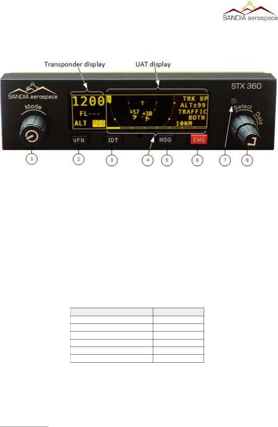
__________________________________________________________________
software information. Each of these pages can be selected by rotating the Select knob
clockwise or counter clockwise to the highlighted page. Once a page is selected, the Select knob, Data knob and
Data button are used to change/select values on each page.
1 – [MODE] Left Encoder with push button
2 – VFR Button
3 – IDENT Button
4 – Pages available on main menu. Highlighted bar is the current page.
5 – Message Button
The STX 360 displays errors/noficaons in the Message page. Message indicator field (le side of dis-
play) blinks when a new message arrives and stays highlighted as long as there are acve messages.
Once all the messages becomes inacve, the highlight goes away. The system could generate the follow-
ing five messages.
When multiple messages are active, the messages shall be listed on a scrollable list based on
their priority as listed in Table 13. The highest priority message will be listed at the top.
www.sandia.aero 306467-00 STX 360 Installaon Manual REV 1
Page 48
Figure 21: STX 360 front panel funconality
Table 13: STX 360 messages and priority
Message Priority Level
INVALID ICAO ADDRESS 1
GPS POSITION ERROR 2
TRANSMIT INCAPABLE 3
GDL90 FAULT 4
ANONYMOUS NOT ACTIVE 5
EMERGENCY NOT ACTIVE 6
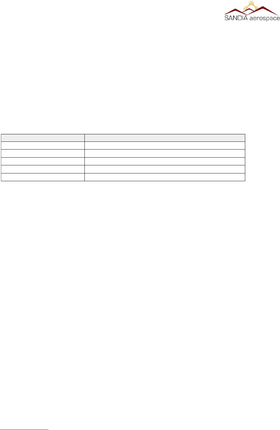
__________________________________________________________________
6 – Emergency Button
Emergency button adds the convenience of built in emergency squawk codes.
7 – Light Sensor
8 – [Select / Data ] Dual concentric Encoder with push button
4.3.1 Traffic display screen
When the unit powers up, the STX 360 defaults to the first page. This first page displays the traffic. Items that can
be changed on this window are:
Each of these items above can be easily changed by first rotating the Data knob one rotation and then rotating the
Select knob to the desired function (highlighted). Once the desired function is highlighted, the Data knob is rotated
to pick the correct setting by rotating clockwise or counter clockwise.
4.3.2 METAR
display screen
Rotating the Select knob clockwise one click (page 2) displays the METAR page. METARs are acquired over time
through ground stations and aircraft. The newest airport information will show on top while the last will be the
bottom of the list. The left pane displays the airport and the right pane displays the METAR data.
4.3.3 GPS Informaon screen
Rotating the Select knob clockwise two clicks (page 3) displays the GPS page. This page displays the latitude and
longitude, GPS altitude, UTC time, ground speed and On Ground/In air status. This allows the user to easily see
GPS information in a clear and concise format. GPS page shall display above listed information if they
are available, otherwise dashes are displayed.
4.3.4 brightness display screen
The brightness page displays/controls the current LCD brightness in terms of percentage. Turning the Top
Right Encoder clockwise/counter clockwise while on Brightness Page shall increase/decrease the
brightness of the display in between 4% to 100% and set the brightness to the selected value
disabling the auto brightness adjustment.
4.3.5 CALL SIGN / TAIL number display screen
The call sign/tail number page allows the user to change the flight id to match to the aircraft. Additionally the mode
C transponder anonymous mode can be changed from this screen.. It must be noted that the anonymous mode can
only be used in VFR mode.
The following steps shall be followed to edit a FLIGHT ID.
1. Press Right Encoder Switch to enable field selection on the current page.
2. Use Bottom Right Encoder to select the FLIGHT ID for editing.
www.sandia.aero 306467-00 STX 360 Installaon Manual REV 1
Page 49
Field Possible Values
Range 0.2, 0.5, 1, 2, 3, 4, 5, 6, 7, 8, 9, 10, 20, 40 nm
Traffic Type BOTH, ON GND, IN AIR
Altitude Disc in Flight Level ±10,15,20,25,30,35,40,45,50,60,70,80,90,99
Track Type TRK UP, NRTH UP
Ownship Position Bottom of the screen to Top of the screen.

__________________________________________________________________
3. Press Right Encoder Switch to initiate editing.
4. Only the first character will be present.
5. Use the Top Right Encoder to select an alphanumeric character.
6. Turn the Bottom Right Encoder clockwise to move to the next character.
7. Steps 5 and 6 can be repeated up to 8 times to select 8 FLIGHT ID characters.
8. Turning the Bottom Right Encoder counter clockwise will delete the previously entered characters.
9. Pressing Right Encoder Switch at any time will set the new Flight Id.
10. No activity for 5±1 seconds will timeout the editing and will restore the previous flight
id.
ANONYMOUS MODE field could be selected to be either YES or NO. The following steps shall be followed to
change the ANONYMOUS MODE state:
1. Press Right Encoder Switch to enable field selection on the current page.
2. Use Bottom Right Encoder to select the ANONYMOUS MODE for editing.
3. Turn Top Right Encoder to select between YES or NO.
4. Pressing Right Encoder Switch or no activity for 5±1seconds will timeout the editing.
If ANONYMOUS MODE is selected YES when the Squawk Code is not the same as the VFR code (coded setup
during configuration), it shall keep the ANONYMOUS MODE to NO and display a message “NOT IN VFR
MODE” until Right Encoder Switch is pressed.
4.3.6 Status Informaon screen
The Status screen displays how many towers were communicated with,
4.3.7 Soware informaon display screen
4.4 UAT system configuraon
4.4.1 GPS1 SOURCE
www.sandia.aero 306467-00 STX 360 Installaon Manual REV 1
Page 50
GPS 1 Source
Not Installed
GARMIN ADSB OUT
GARMIN ADSB OUT+
FFS1201
ARINC 429 1
ARINC 429 2
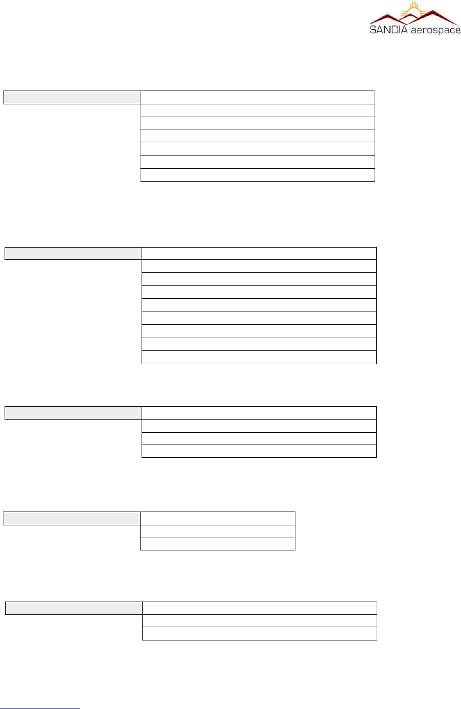
__________________________________________________________________
4.4.2 GPS2 source selecon screen
4.4.3 Airdata source selecon screen
4.4.4 Radar Almeter source selecon screen
4.4.5 Altude source selecon screen
4.4.6 AIR/GROUND Discrete selecon screen
www.sandia.aero 306467-00 STX 360 Installaon Manual REV 1
Page 51
Altitude Source
Pressure – ADC
GEOMETRIC – GPS
GPS 2 Source
Not Installed
GARMIN ADSB OUT
GARMIN ADSB OUT+
FFS1201
ARINC 429 1
ARINC 429 2
Air data Source
Not Installed
SANDIA ICARUS
SANDIA EXTENDED
GARMIN Z FORMAT
SAI 340
KING C
ARINC 429 1
ARINC 429 2
RALT Source
NOT INSTALLED
ARINC 429 1
ARINC 429 2
AIR / GROUND DISCRETE
VALID
INVALID
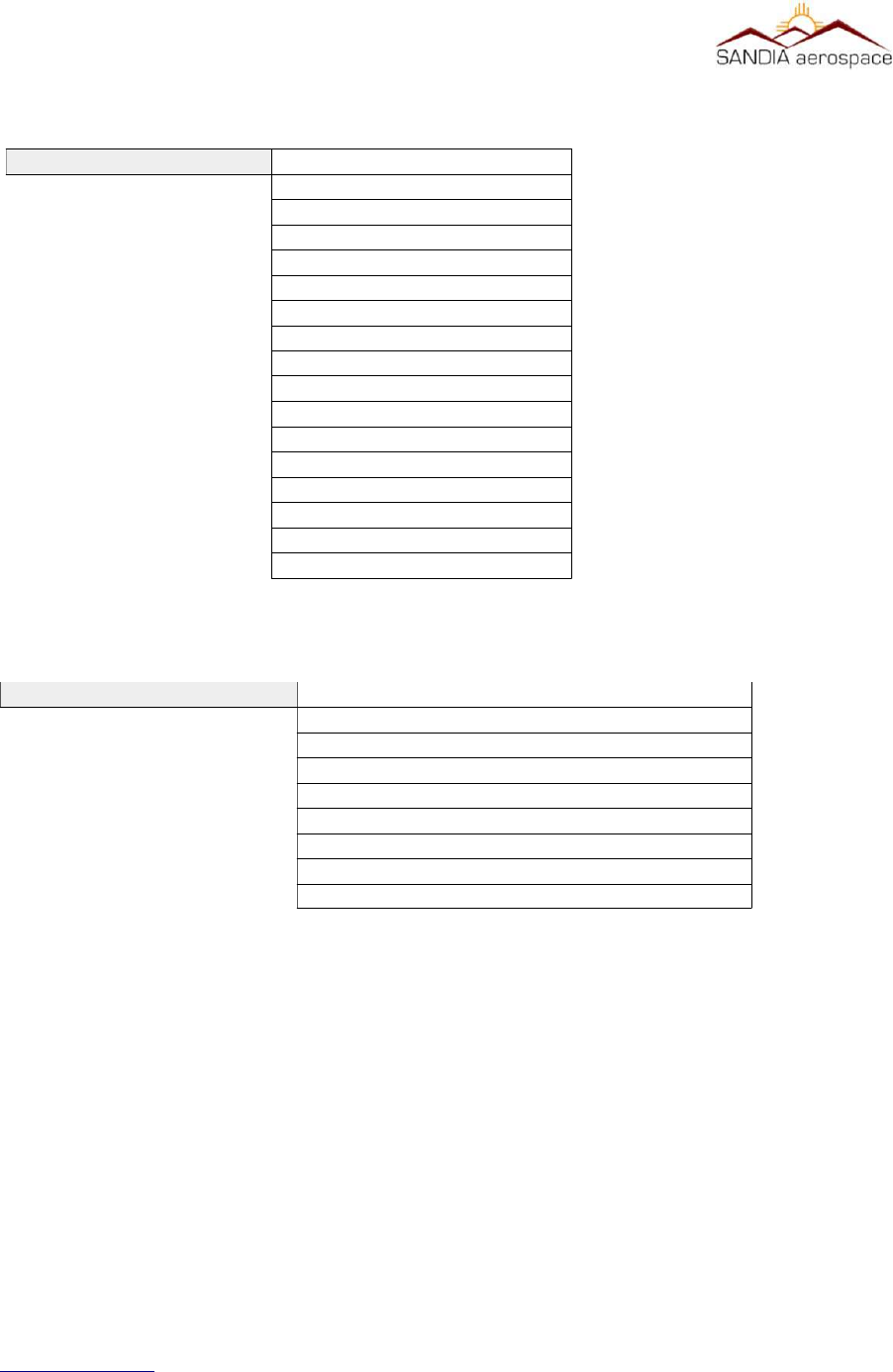
__________________________________________________________________
4.4.7 AIR VEHICLE LENGTH
Menu of lengths from < 15 m to >85m and widths from < 23m to > 80m
4.4.8 GPS 0 ANTENNA LAT OFFSET MENU
www.sandia.aero 306467-00 STX 360 Installaon Manual REV 1
Page 52
Air Vehicle Length
Not Available
Length <15m Width<23m
Length <25m Width<28.5m
Length <25m Width<34m
Length <35m Width<33m
Length <35m Width<38m
Length <45m Width<39.5m
Length <45m Width<45m
Length <55m Width<45m
Length <55m Width<52m
Length <65m Width<59.5m
Length <65m Width<67m
Length <75m Width<72.5m
Length <75m Width<80m
Length <85m Width<80m
Length >=85m Width>=80m
GPS 0 ANTENNA LAT OFFSET
NOT AVAILABLE
2 METERS TO LEFT
4 METERS TO LEFT
6 METERS TO LEFT
0 METERS TO RIGHT
2 METERS TO RIGHT
4 METERS TO RIGHT
6 METERS TO RIGHT

__________________________________________________________________
4.4.9 GPS 0 ANTENNA LON OFFSET MENU
www.sandia.aero 306467-00 STX 360 Installaon Manual REV 1
Page 53
GPS 0 ANTENNA LON OFFSET
NOT AVAILABLE
OFFSET APPLIED BY GPS
2 METERS FROM NOSE
4 METERS FROM NOSE
6 METERS FROM NOSE
8 METERS FROM NOSE
10 METERS FROM NOSE
12 METERS FROM NOSE
14 METERS FROM NOSE
16 METERS FROM NOSE
18 METERS FROM NOSE
20 METERS FROM NOSE
22 METERS FROM NOSE
24 METERS FROM NOSE
26 METERS FROM NOSE
28 METERS FROM NOSE
30 METERS FROM NOSE
32 METERS FROM NOSE
34 METERS FROM NOSE
36 METERS FROM NOSE
38 METERS FROM NOSE
40 METERS FROM NOSE
42 METERS FROM NOSE
44 METERS FROM NOSE
46 METERS FROM NOSE
48 METERS FROM NOSE
50 METERS FROM NOSE
52 METERS FROM NOSE
54 METERS FROM NOSE
56 METERS FROM NOSE
58 METERS FROM NOSE
60 METERS FROM NOSE

__________________________________________________________________
4.4.10 GPS 1 ANTENNA LAT OFFSET MENU
4.4.11 GPS 1 ANTENNA LON OFFSET MENU
www.sandia.aero 306467-00 STX 360 Installaon Manual REV 1
Page 54
GPS 1 ANTENNA LAT OFFSET
NOT AVAILABLE
2 METERS TO LEFT
4 METERS TO LEFT
6 METERS TO LEFT
0 METERS TO RIGHT
2 METERS TO RIGHT
4 METERS TO RIGHT
6 METERS TO RIGHT
GPS 1 ANTENNA LON OFFSET
NOT AVAILABLE
OFFSET APPLIED BY GPS
2 METERS FROM NOSE
4 METERS FROM NOSE
6 METERS FROM NOSE
8 METERS FROM NOSE
10 METERS FROM NOSE
12 METERS FROM NOSE
14 METERS FROM NOSE
16 METERS FROM NOSE
18 METERS FROM NOSE
20 METERS FROM NOSE
22 METERS FROM NOSE
24 METERS FROM NOSE
26 METERS FROM NOSE
28 METERS FROM NOSE
30 METERS FROM NOSE
32 METERS FROM NOSE
34 METERS FROM NOSE
36 METERS FROM NOSE
38 METERS FROM NOSE
40 METERS FROM NOSE
42 METERS FROM NOSE
44 METERS FROM NOSE
46 METERS FROM NOSE
48 METERS FROM NOSE
50 METERS FROM NOSE
52 METERS FROM NOSE
54 METERS FROM NOSE
56 METERS FROM NOSE
58 METERS FROM NOSE
60 METERS FROM NOSE
__________________________________________________________________
4.4.12 EMITTER CATEGORY
4.4.13 OUTPUT MESSAGE FORMAT MENU
4.4.14 ETHERNET FORMAT MENU
4.4.15 CALL SIGN ID TRANSMIT MENU
www.sandia.aero 306467-00 STX 360 Installaon Manual REV 1
Page 55
Emitter Category
No Aircraft Information
Light < 15500 lbs
Small 15500 to 75000 lbs
Large 75000 to 300000 lbs
high vortex large
Heavy > 300000 lbs
Highly Maneuverable > 5G
Rotorcraft
Glider Sailplane
Lighter than air
Parachutist Sky Diver
Ultralight Glider
Unmanned Aerial Vehicle
Transatmospheric Vehicle
Surface Emergency Vehicle
Surface Service Vehicle
Point Obstacle
Tethered Balloons
Cluster Obstacle
Line Obstacle
Output Message Format
GDL 90
RAW
Ethernet Format
GDL 90
WINGX PRO
FOREFLIGHT
Call Sign ID transmit
ENABLED
DISABLED

__________________________________________________________________
4.4.16 STALL SPEED
Configurable from 0 Knots to 150 Knots
4.4.17 ADC ALTITUDE ACCURACY
Configurable from 0 Feet to 125 Feet
4.4.18 GPS LON OFFSET
Configurable from 0 Feet to 125 Feet
4.4.19 MAX GROUND MSG PER SEC
Configurable from 1 message per second to 5 messages per second
4.4.20 AUTO MODE C ALTITUDE
Configurable from 0 Feet to 500 Feet
4.4.21 XPDR REPLY RATE LIMIT
Configurable from500 replies per second to 12 replies per second
4.4.22 A/C LOW VOLTAGE THRESHOLD
Configurable from 10 Volts to 32 Volts
4.4.23 Default VFR
Squawk code default is 1200, however this squawk code can be defaulted to any squawk code. Once
configured, pressing the VFR buon will show the defaulted squawk code.
4.4.24 ICAO ADDRESS
ICAO address default is ADFBA4, however this address can be set from 000000 to FFFFFF. This is
accomplished by pressing the data encoder to highlight the digit. The highlighted digit is then changed
by turning the data encoder clockwise/counterwise. Once the correct value is selected, turning the
select clockwise/counterwise to advance to the next/previous digit. Pressing the Data buon will
deselect the highlighted value. Once the new address is correct and shown with brackets, press the
Mode buon to return to main menu.
4.5 Connued Airworthiness
4.5.1 STX 360 Panel Mounted Unit
Continued Airworthiness of the STX 360 panel mount is on condition only
4.5.2 STX 360R Remote
Continued Airworthiness of the STX 360R Remote is on condition only
5.0 Wiring Interconnecon diagrams
This section shows the different types of equipment that interface with the STX 360 SENTINEL.
www.sandia.aero 306467-00 STX 360 Installaon Manual REV 1
Page 56

__________________________________________________________________
www.sandia.aero 306467-00 STX 360 Installaon Manual REV 1
Page 57
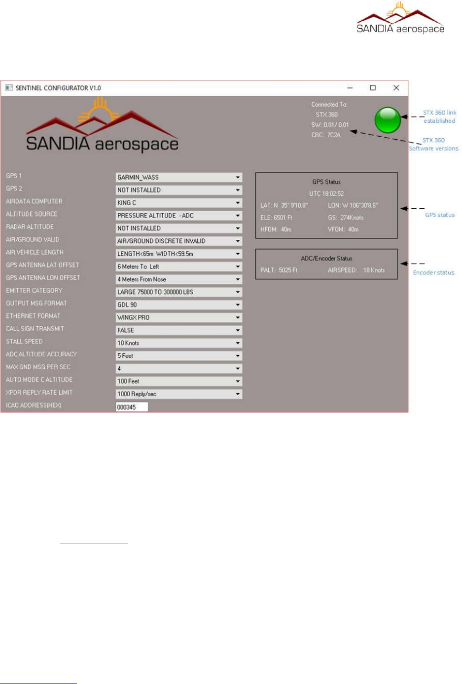
__________________________________________________________________
Appendix A – Sandia Aerospace STX360 configuraon applicaon
This appendix describes the Sandia Aerospace configuration tool that can be used for configuring all menus
described in section 4.4 UAT system configuration . Following the steps below for configuring the STX 360 and
STX 360R.
1. Make sure the Windows computer that will be used has a serial port or a USB to serial port adapter working
prior to the next step.
2. Go to www.sandia.aero and get the lastest STX 360 Configurator installer download.
3. Run the windows installer and follow the steps.
4. Before running the program, make sure to connect the serial port on the PC to the maintenance port on the
STX 360. Please see pin out information located in section 3.7.2, section 3.7.3 and figure 26 shows the the
minimum interfaces while using the STX 360 Configurator.
5. Connect an altitude encoder as shown in figure 16. Verify all connections per section 3.7.2 and section
3.7.3.
www.sandia.aero 306467-00 STX 360 Installaon Manual REV 1
Page 58
Figure 22: Sandia Aerospace Configuraon tool

__________________________________________________________________
6. Connect an WAAS GPS source as shown in figure 14. Verify all connections per
section 3.7.2 and section 3.7.3.
7. Ensure the STX 360 antenna port is connected to a load /antenna prior to powering up the unit.
8. Power up the STX 360, the green light should be present. If not check the wiring connection to the
maintenance port [pins 6, 7 ].
9. Once connections are made, run the software. The software will try to communicate with the STX 360. If
a connection is made, a green light will be visible on the top right corner of the software. This indicates a
communication link has been established.
10. Select the proper GPS timing source from the pull down menu.
11. Power GPS and make sure it is connected to the STX 360. If the connections are correct, GPS status
information should be present. If only dotted lines are present, review the connections between the STX
360 and the GPS. Additionally make sure the correct GPS is selected from the pull down menu.
12. Select the proper encocoder from the pull down menu.
13. Power Encoder and make sure it is connected to the STX 360. If the connections are correct, encoder status
information should be present. If only dotted lines are present, review the connections between the STX
360 and the encoder. Additionally make sure the correct encoder is selected from the pull down menu.
14. The other pull down menus are for configuring the STX 360 and as long as the STX 360 light is green, the
data selected will be sent to the STX 360.
Below are error conditions when STX 360 link is not established, GPS link failure and Encoder link failure:
www.sandia.aero 306467-00 STX 360 Installaon Manual REV 1
Page 59
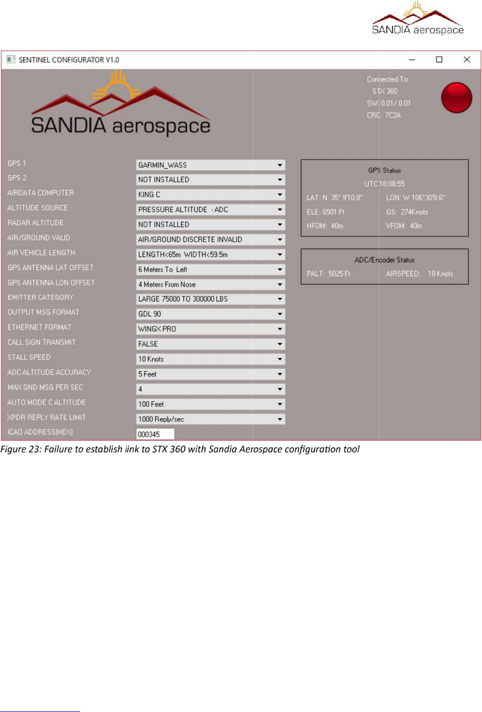
__________________________________________________________________
www.sandia.aero 306467-00 STX 360 Installaon Manual REV 1
Page 60
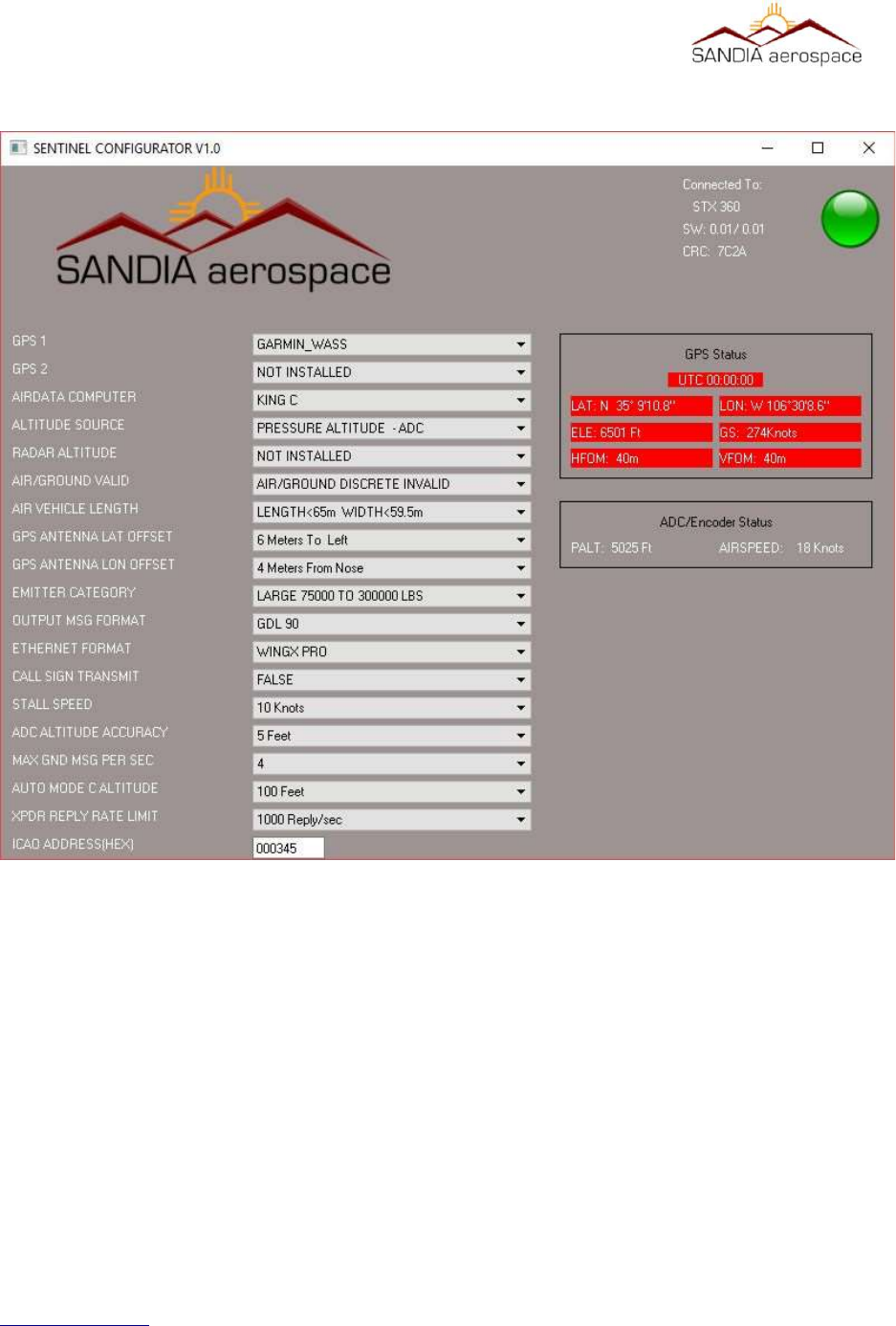
__________________________________________________________________
www.sandia.aero 306467-00 STX 360 Installaon Manual REV 1
Page 61
Figure 24: Failure to establish link with GPS
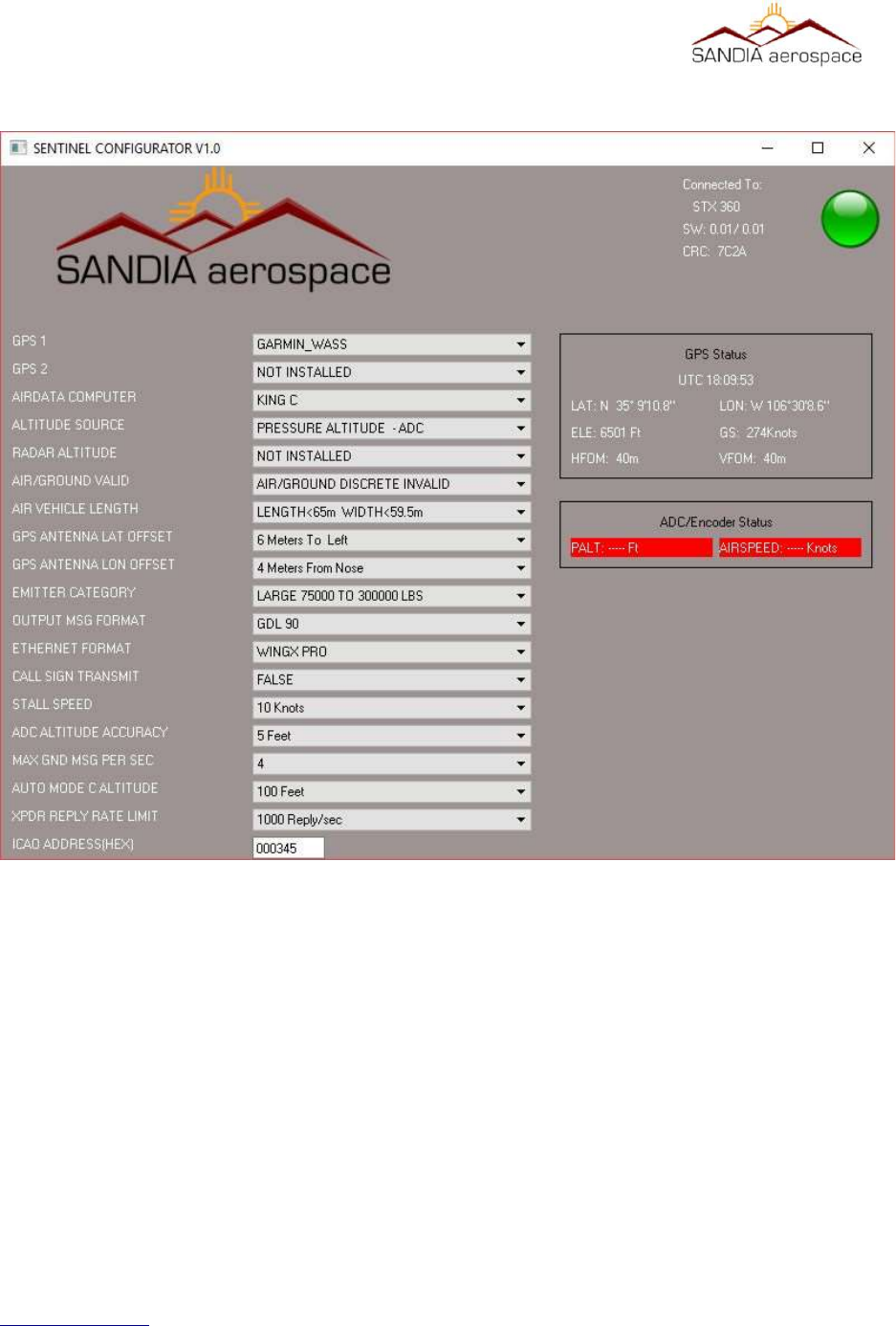
__________________________________________________________________
www.sandia.aero 306467-00 STX 360 Installaon Manual REV 1
Page 62
Figure 25: Failure to establish link with Encoder
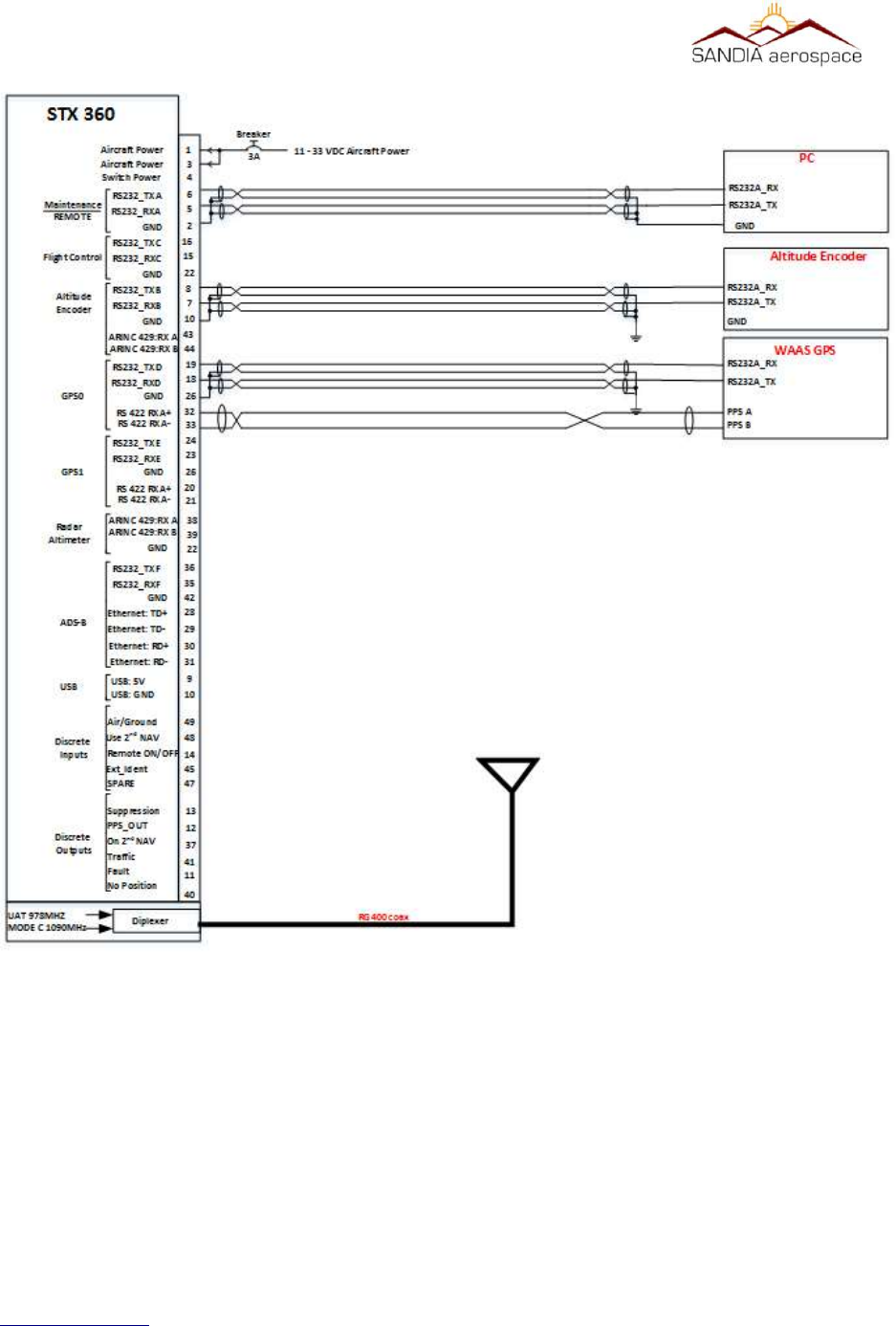
__________________________________________________________________
www.sandia.aero 306467-00 STX 360 Installaon Manual REV 1
Page 63
Figure 26: Minimum system setup when using the STX 360 Configuator soware