Saris Cycling Group CPU2FT3 Bicycle Monitoring Transmitter User Manual Rev 29 After Translations Joule 2 indd
Saris Cycling Group Inc Bicycle Monitoring Transmitter Rev 29 After Translations Joule 2 indd
Contents
- 1. manual
- 2. final manual
final manual
Joule 2.0 User Guide page 1
The Leader in P o we r .
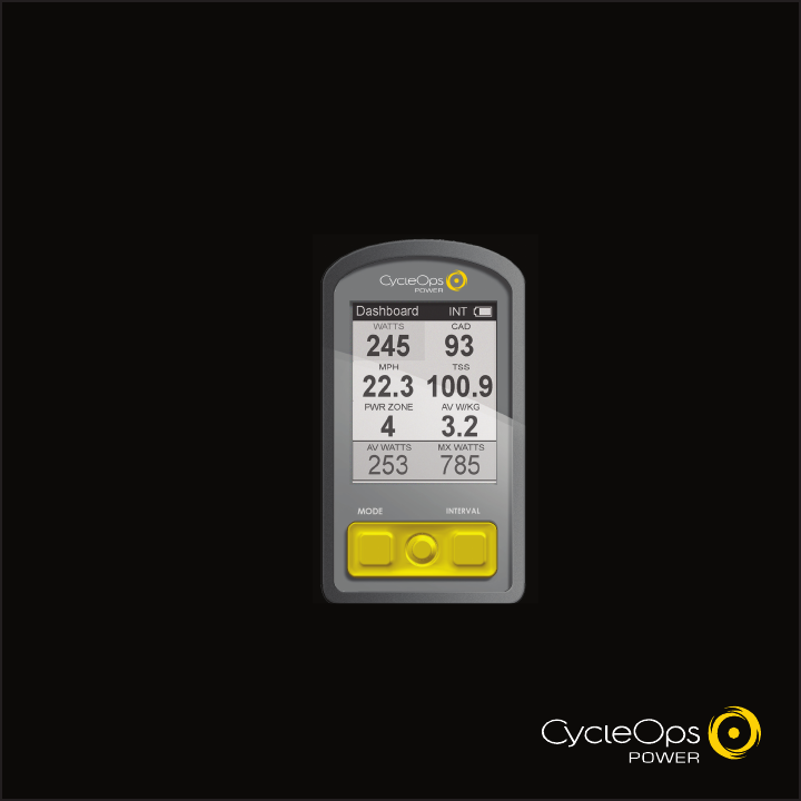
CycleOps Joule™ 2.0
User Guide

Joule 2.0 User Guide page 2
Joule 2.0 User Guide page 3
© 2009 Saris Cycling Group, Inc.
5253 Verona Road
Madison WI 53711 USA
Telephone: 800.783.7257 or 608.274.6550
Fax: 608.274.1702
All rights reserved. No part of this publication may be copied, photographed, reproduced, translated,
transmitted electronically or placed on digital media without the prior written consent of Saris Cycling
Group, Inc.
Trademarks
Saris Cycling Group, Inc , Joule 2.0, Joule 3.0, CycleOps, CycleOps logo, PowerTap and the PowerTap logo,
are all registered trademarks of Saris Cycling Group, Inc. All other product, brand, or trade names used in
this manual may be trademarks or registered trademarks of their respective owners.
Modifications
Saris Cycling Group, Inc reserves the right to make improvements and/or updates to the products
described herein at any time without notice.
Table of Contents: Chapters
1. Starting Out....................................................................................................................................5
Compatibility................................................................................................................6
Installing CycleOps Joule 2.0 Using Standard Mount....................................7
CycleOps (ANT+) Heart Rate Strap........................................................................9
Charging Battery.......................................................................................................10
Installing MicroSD Card..........................................................................................11
2. Navigation....................................................................................................................................12
Overview of CycleOps Joule™ 2.0......................................................................13
3.Data File Management.............................................................................................................14
Pausing, Saving and/or Deleting a Ride...........................................................15
3. Dashboard Mode.......................................................................................................................18
Alerts.............................................................................................................................18
Using Dashboard......................................................................................................19
Dashboard Categories............................................................................................21
4. Intervals.........................................................................................................................................22
5. Reports Mode..............................................................................................................................23
Using Reports............................................................................................................23
Report Details............................................................................................................27
Report Definitions....................................................................................................29

Joule 2.0 User Guide page 4
Joule 2.0 User Guide page 5
Chapter 1: Starting Out
Thank you for purchasing CycleOps Joule 2.0, the first cycling computer designed for cyclists who
train with power.
This user guide is just one of the resources to help you understand all the features Joule 2.0 has to
offer.
Please visit www.cycleops.com to:
Learn more about Joule 2.0 and the CycleOps system of products including stationary •
trainers, indoor cycles, software and power meters
Register all CycleOps products and activate warranty•
View instructional videos•
Sign up for the CycleOps Power newsletter- your source for the latest news and techni-•
cal updates from CycleOps Power
WARNING: Always consult a physician before beginning or modifying any exercise program.
Unpacking Joule 2.0
Remove all parts from the box to ensure the following contents are included:
PACKAGE CONTENTS:
Item Part Description Qty
Joule 2.0 computer 1•
Heart rate strap 1•
Standard mount 1•
Indoor cycle mount 1•
Mount bolts 2•
Mount knobs 2•
Training with Power DVD 1•
PowerAgent CD 1•
USB cable 1•
Please contact your local dealer or Saris Cycling Group with any questions at 1-800-783-7257.
6. Workouts.......................................................................................................................................35
Using Workouts.........................................................................................................35
Using Manual Workouts on CycleOps 400 Pro Indoor Cycle.....................37
Using Manual Workouts on CycleOps PowerBeam Pro Trainer................39
Using Saved Workouts on CycleOps 400 Pro Indoor Cycle........................41
Using Saved Workouts on CycleOps 400 Pro Indoor Cycle........................43
Pausing, Saving and/or Deleting a Workout....................................................45
7. Sensors...........................................................................................................................................46
Setting Up....................................................................................................................46
Calibrating Devices..................................................................................................53
8. Setup CycleOs Joule ™ 2.0......................................................................................................62
9. Setup User.....................................................................................................................................64
10. History..........................................................................................................................................66
Previous Rides............................................................................................................66
Maximum History......................................................................................................67
Total History................................................................................................................68
11. Troubleshooting CycleOps Joule™ 2.0.............................................................................69
12. Important Precautions...........................................................................................................70
13. Technical Specifications for CycleOps Joule ™ 2.0......................................................73
14. CycleOps Joule™ 2.0 Warranty............................................................................................74
14. Definition of Common Training Terms.............................................................................75
Table of Contents: Chapters...continued

Joule 2.0 User Guide page 6
Joule 2.0 User Guide page 7
Chapter 1: Starting Out
Compatibility
Joule 2.0 is compatible with any ANT+ compatible power meter, speed sensor, cadence sensor
or heart rate strap. For more information on ANT+ compatible devices, please visit www.thisi-
sant.com. Note: Joule 2.0 is not compatible with combination speed/cadence sensors, wired
version of PowerTap and non-ANT+ PowerTap models such as the SL 2.4.
In addition, Joule 2.0 is compatible with the following CycleOps products:
PowerTap 2.4+ Power Meter1.
PowerTap Elite+ Power Meter2.
PowerTap Pro+ Power Meter3.
PowerTap SL+ Power Meter4.
PowerTap SLC+ Power Meter5.
PowerBeam Pro Trainer*6.
200 Pro Indoor Cycle7.
300 Pro Indoor Cycle8.
400 Pro Indoor Cycle*9.
CycleOps PowerAgent Software10.
*Important: Unit must be plugged in to work with Joule.
Chapter 1: Starting Out
3. Slide Joule 2.0 forward into
mount until it snaps into place.
5. To remove Joule 2.0 , press down on
the release lever and slide Joule 2.0
back. Note: additional sticky pads may
be used if release lever is not acces-
sible due to stem length or angle.
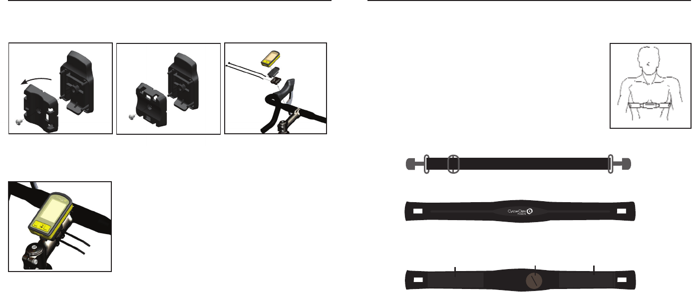
Installing CycleOps Joule™ 2.0 Using Standard Mount
The standard mount can be installed in either stem or handlebar orientations for use on any
handlebar or stem. The mount is preassembled for the stem orientation.
1. For stem orientation insert two
zip ties through bottom of mount
and attach sticky pad. Secure to
stem.
2. Position Joule 2.0 slightly behind
mount.
4. Be sure to check Joule 2.0 is
secure in mount before riding.
Press to
release
Joule 2.0 User Guide page 8
Joule 2.0 User Guide page 9
Chapter 1: Starting Out
2. Insert screw threw bottom of
mount.
3. Insert two zip ties through bot-
tom of mount. Apply sticky pad and
tighten zip ties to secure mount.
1. Remove screw that holds
bottom of mount and rotate 90
degrees.
Installing CycleOps Joule™ 2.0 Using Standard Mount
For handlebar orientation, change the standard mount from the preassembled stem orientation.
4. Handlebar orientation. Be sure
to check Joule 2.0 is secure in
mount before riding.
CycleOps (ANT+) Heart Rate Strap
Wearing the heart rate strap, position it above torso as pictured. The
strap should rest just beneath the pectoralis muscles of the chest. For
best results slightly moisten the electrodes where contact is made with
skin. The heart rate strap must be worn to enable the heart rate function.
It should be snug enough to stay in place during the ride.
NOTE: Joule 2.0 is compatible with any ANT+ compatible heart rate strap.
The CycleOps heart rate strap contains a user replaceable CR2032 bat-
tery; with an expected life of three years, assuming one hour of use per
day. After replacing sensor battery, Joule must be re-paired to heart rate
sensor. See Sensor section on page 39.
Chapter 1: Starting Out
Band
Front of Heart Rate Strap
Back of Heart Rate Strap
Electrodes
Electrodes Battery Door
Joule 2.0 User Guide page 10
Joule 2.0 User Guide page 11
Charging Battery
The Joule 2.0 is powered by a user replaceable lithium-ion battery that can be recharged using
the included USB cable and a computer. A 5VDC 400mA charger can also be used (not included).
A fully charged battery can run for approximately 20 hours before it must be recharged. Recharg-
ing completely, via USB cable or AC adapter will take approximately six hours. The battery level is
indicated in the title bar. The Joule 2.0 is fully charged at the factory, but shipping and handling
may inadvertently consume charge. For more information see Important Precautions section on
page 38.
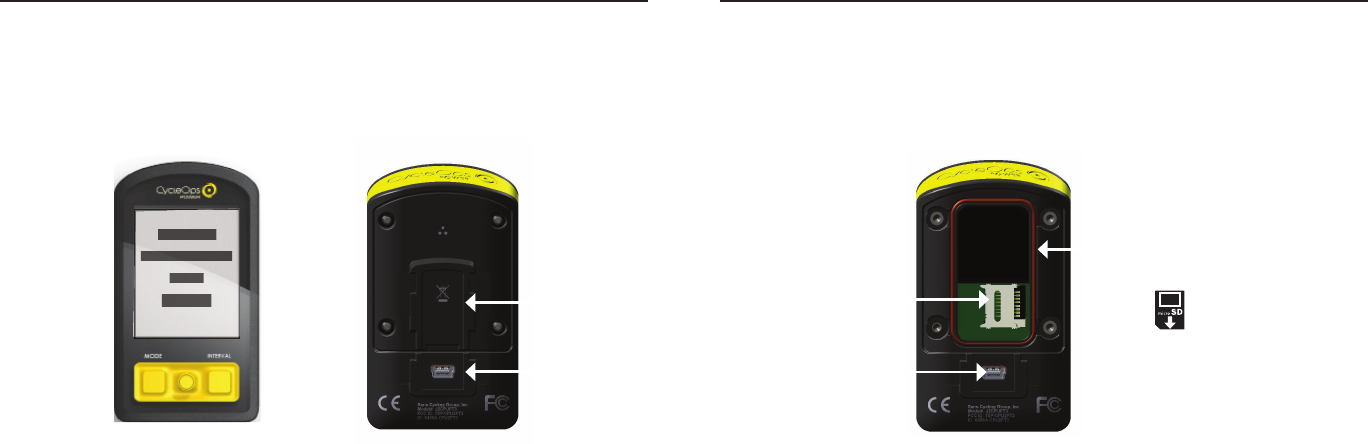
Chapter 1: Starting Out
1. Press in release [MODE] button or [INTERVAL] button to turn on Joule 2.0. Note: Pressing [JOYSTICK] will not
turn Joule 2.0 on.
2. Plug the mini-USB cable into the mini-USB port on the back of Joule 2.0 and plug the other end into an avail-
able USB port on a computer.
3. A standard AC adapter to wall outlet is available separately.
4. Once connected to a computer or AC adapter, Joule 2.0 displays the connection and charge screen (charging
or charge complete). No data will be displayed.
Connected
Firmware Version
14.045
Charging
Mini-
USB
port
Front of Joule Back of Joule
Chapter 1: Starting Out
Mini-USB
port
Installing MicroSD Card
Joule 2.0 provides 4 MB of onboard memory for storing activities, history and workouts. Activity
fi le size increases with ride time but a one hour ride is approximately 150 KB, history fi les are
always 1 KB (1,000 history fi les = 1 MB) and workout fi les also increase with workout size but a
workout containing 500 segments will be approximately 50 KB. A microSD card slot is available
under the battery for additional memory. Once a microSD card is installed, all fi les are stored on
the card. For more information see Data Management section on page 16.
MicroSD
card
holder
1. Remove the four screws attaching battery cover to Joule 2.0.
2. Remove battery cover. Remove battery. Note: disconnecting the battery is not necessary. Be careful not to
damage the o-ring
3. Slide microSD card into microSD card holder, behind battery.
4. Attach battery cover and four bolts, using screwdriver. Make sure red O-ring is clean and in place before
attaching battery cover. O-rings should be inspected and replaced if necessary whenever the battery cover is
removed. Use a light coating of grease when re-installing the battery cover on the O-rings.
Battery
cover
Red O-ring
Joule 2.0 User Guide page 12
Joule 2.0 User Guide page 13
Chapter 1: Starting Out
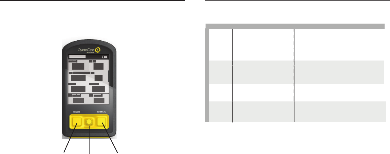
[MODE] button [JOYSTICK] [INTERVAL] button
Navigation Overview CycleOps Joule™ 2.0
There are two buttons and one [JOYSTICK] to navigate Joule 2.0. To help navigate Joule 2.0 display
and this user guide note; bold letters will bring special attention to Menu items as they appear
on the screen. Letters appearing in all [CAPs] denote an actual button.
Chapter 1: Starting Out
Button Function
[JOYSTICK] Press left/right Move within a screen or change screens
Press up/down Move within a screen or scroll up/down screen
Press in and release Change metrics in dashboard, change date
ranges in reports or select settings in menu
Press and hold for 2 seconds Initate list for changing dashboard categorysettings
[MODE] Press and release Change between dashboard, reports, activities,
menu
Press and release Navigate “back” in menu mode
Press and hold for 2 seconds Display “Ride Paused” screen
[INTERVAL] Press and release Stop current interval and start next interval
Press and hold for 2 seconds Change dashboard to and from “Interval Mode”
[MODE] Press and hold for 2 seconds Initiates fi nding previously paired sensors
+
[INTERVAL]
Display Actions
Navigation Overview CycleOps Joule™ 2.0
[JOYSTICK] Press left/right Move within a screen or change screens
Press up/down Move within a screen or scroll up/down screen
Press in and release Change metrics in dashboard, change date
ranges in reports or select settings in menu
Press and hold for 2 seconds Initate list for changing dashboard categorysettings
[MODE] Press and release Change between dashboard, reports, activities,
menu
Press and release Navigate “back” in menu mode
Press and hold for 2 seconds Display “Ride Paused” screen
[INTERVAL] Press and release Stop current interval and start next interval
Press and hold for 2 seconds Change dashboard to and from “Interval Mode”
[MODE] Press and hold for 2 seconds Initiates fi nding previously paired sensors
Dashboar
d
W/
W/
W/
KG
MX
WA
TT
WATTWA
S
AV
WA
TT
WATTWA
S
212
876
407
5.2
MP
HC
HC
AD
27.4
98
MILES
FT GAIN
37.8
987
WA
TT
WATTWA
S
Joule 2.0 User Guide page 14
Joule 2.0 User Guide page 15
Chapter 1: Starting Out
Data File Management
Joule 2.0 saves three types of fi les into memory, activities, workouts and history. Activities fi les
contain second by second ride data for analysis by PC or Mac on software such as CycleOps
PowerAgent. History fi les contain summary data only and are used by Joule 2.0 for calculating
averages, maximums and totals for Reports. Workout fi les are created in PowerAgent and sent to
Joule 2.0.
Whenever ride time is accumulated an activities fi le is created and saved automatically. A history
fi le is generated anytime a ride is stopped and saved. Note: because history fi les are used by
Reports for calculating averages, maximums and totals it is important to manage them carefully,
only saving rides that you want to contribute to these calculations. Because Joule 2.0 acts as a
mass storage device, activities and history fi les may also be viewed from a PC or Mac when con-
nected via USB cable.
File Type Description Size
Activtiies Second by second complete ride storage 1hr=150K
Workouts Summarized ride data for reports and history 1 ride=1KB
History Created by PowerAgent for training a precise power
output, powerzone or terrain (slope).
500 segments=5KB
Chapter 1: Starting Out
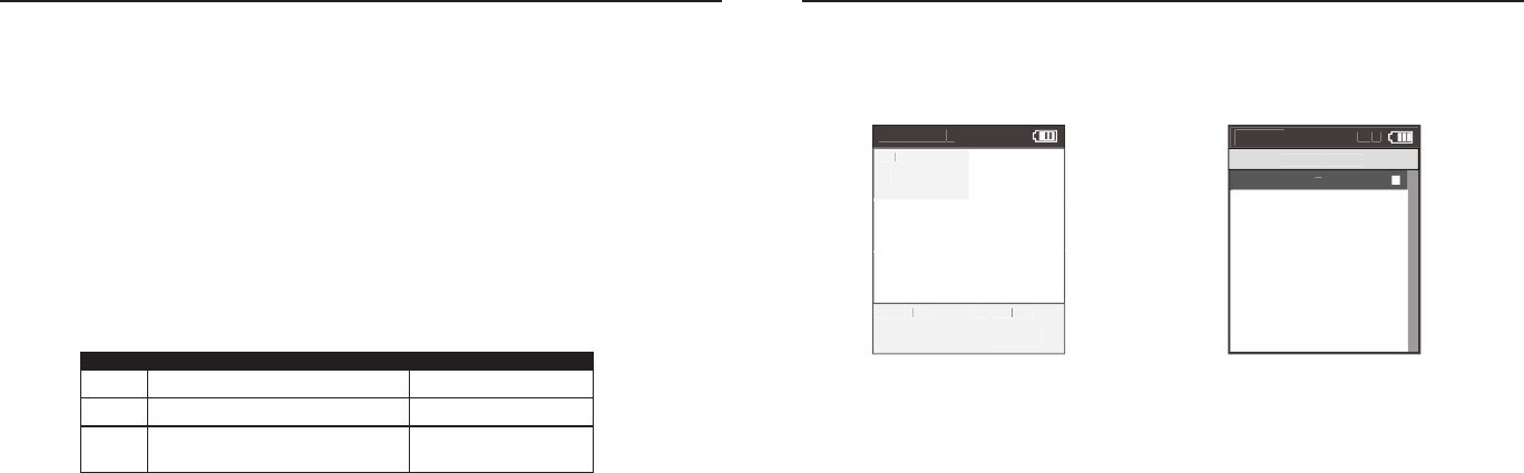
Pausing, Saving and/or Deleting a Ride
A ride may be paused at any time. Joule 2.0 will turn off automatically if paused for longer than
the designated sleep time. See page 34 for how to change sleep time.
1. Press and hold [MODE] button for two seconds
to access ride paused screen from any mode.
2. Press [JOYSTICK] in and release to resume ride.
Dashboar
d
W/
W/
W/
KG
MX
WA
TT
WATTWA
S
AV
WA
TT
WATTWA
S
212
876
407
5.2
MP
HC
HC
AD
27.4
98
MILES
FT GAIN
37.8
987
WA
TT
WATTWA
S
>
Resume rid
e
>
>
>
>
Stop and Save
>
Stop and Delete
>
12:02p
IN
T
Ride P
aused
Joule 2.0 User Guide page 16
Joule 2.0 User Guide page 17
Chapter 1: Starting Out
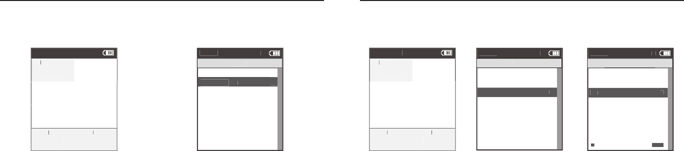
Pausing, Saving and/or Deleting a Ride
Stopping and saving a ride creates a history fi le. History fi les are used for calculating averages,
maximums and totals for Reports.
1. Hold [MODE] button for
two seconds to access ride
paused screen from any mode.
2. Press [JOYSTICK] up/down
to highlight stop and save.
Press [JOYSTICK] in and
release to select.
Chapter 1: Starting Out
Pausing, Saving and/or Deleting a Ride
A ride may be deleted at any time. If a ride is deleted no history fi le is created.
1. Press and hold [MODE]
button to access ride paused
screen from any mode.
2. Press [JOYSTICK] up/down
to highlight stop and delete.
Press [JOYSTICK] in and re-
lease to select stop and delete.
3. Press [JOYSTICK] in and
release to confi rm deletion.
Dashboar
d
W/
W/
W/
KG
MX
WA
TT
WATTWA
S
AV
WA
TT
WATTWA
S
212
876
407
5.2
MP
HC
HC
AD
27.4
98
MILES
FT GAIN
37.8
987
WA
TT
WATTWA
S
Dashboar
d
W/
W/
W/
KG
MX
WA
TT
WATTWA
S
AV
WA
TT
WATTWA
S
212
876
407
5.2
MP
HC
HC
AD
27.4
98
MILES
FT GAIN
37.8
987
WA
TT
WATTWA
S
Resume rid
e
>
Stop and
Sa
ve
>
Menu
IN
T
Ride
Stop and Delete
>
Resume rid
e
>
Stop and Save
Menu
IN
T
Ride
Stop and Delete
>
>
Are you sure
Are you sure
No
Exit to Main Menu
<
Menu
IN
T
Stop and Delete
Stop and DeleteStop and Delete
Ye
s
>
>
<
<
<
<
Back
Exit to Main Menu
Back
Exit to Main Menu

Joule 2.0 User Guide page 18
Joule 2.0 User Guide page 19
Alerts
Notifi cations indicated in the title bar alerting users to prepare to action step to optimize Joule
2.0 functionality.
Battery Low: indicating Joule 2.0 battery is low. Need to plug in and charge to computer or AC
adapter. If one bar remains on the battery icon, there is approximately a half an hour of use left
before Joule 2.0 battery dies.
Connected: indicating Joule 2.0 is connected to a computer or AC adapter and is receiving a
charge. Charging may take three hours to complete.
Hub Battery Low: indicating the CycleOps PowerTap hub battery is low. Reference CycleOps Pow-
erTap User Guide to change battery in hub.
Finding: indicatingJoule 2.0 is attempting to fi nd activated sensors.
RU Lost: indicating the resistance unit that was activated and paired to Joule 2.0 has been lost.
Hub Lost: indicating the power meter that was activated and paired to Joule 2.0 has been lost.
Memory Full: indicating the memory on the Joule 2.0 has reached its limit. Insert new microSD
card or delete fi les to create more memory.
Title bar
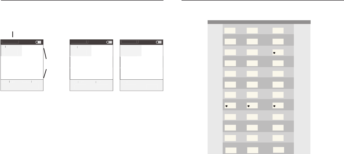
Chapter 2: Dashboard Mode
Dashboard
Detailed
view
Using Dashboard Mode
Joule 2.0 has four modes of operation: dashboard, reports, activities and menu indicated by the
title bar. Note: after the mode is displayed in the title bar for fi ve seconds, the time of day will be
displayed. Press and release [MODE] button to change to dashboard mode.
Selected
metric
Battery
indicator
Interval
On/Off
Mode level
indicator
Dashboar
d
W/
W/
W/
KG
MX
W
AT
WAT W
TS
AV
W
AV WAV
AT
WAT W
TS
212
876
402
402
5.2
MP
HC
HC
AD
27.4
98
MILES
FT GAIN
37.8
987
WA
TT
WATTWA
S
IN
T
Chapter 2: Dashboard Mode
Joule 2.0 User Guide page 20
Joule 2.0 User Guide page 21
1. Press [JOYSTICK] left/right
or up/down to highlight a
metric. Note: when a new met-
ric is highlighted, the detailed
view changes to show related
metrics.
2.Press in and release [JOY-
STICK] to rotate metrics from
detailed view to dashboard.
(Example: watts, av watts, mx
watts).
3. Press in and hold [JOYSTICK]
to change the metric category
displayed in the dashboard.
Chapter 2: Dashboard Mode
Using Dashboard Mode
Dashboard mode shows current ride data. It displays six metrics, out of a choice of eighteen,
that can be easily customized. The detailed view shows additional metrics related to the selected
metric in the dashboard.
Detailed view
Selected
metric
Chapter 2: Dashboard Mode
Dashboard Categories
Each dashboard category is made up of three metrics. There are twelve available dashboard cat-
egories. Press and hold [JOYSTICK] to change the metric category displayed in the dashboard.
Category Metric 1Metric 2Metric 3
Watts watts average watts
average watts/kg
current power zone average power zone
maximum watts/kg
maximum watts
Watts/kg watts/kg
Zones
Peak Power
Scores
Work
Speed
VAM
2999 29992999
WATTS
W/KG
AV W ATTSMXWA T TS
20.0
PWR ZONE
6
AV PWR ZONE
4.2
heart rate zone
HR ZONE
3
5sec Peak Power 5min Peak Power
5 SEC
2999
5 MIN
2999
20 min Peak Power
20 MIN
2999
training stress score normalized power
TSS
500.1
NORM PWR
2999
intensity factor
IF
2.000
kilojoules kilojoules / hour
KJ
9999
KJ/HR
9999
training stress score
TSS
9999
RPM rpmaverage rpm
CAD
250
AV CAD
250
maximum rpm
MX CAD
250
current speed average speed
MPH
99.9
AV MPH
99.9
maximum speed
MX MPH
99.9
current grade current altitude ft or m
current altitude ft or m
% GRADE
45.0
ALTITUDE FT
29999
total ascent ft or m
total ascent ft or m
FT GAIN
9999
vertical ascent
VA M
Heart Rate
% Grade
heart rate average heart rate
HR
250
AV HR
250
MX HR
250
maximum heart rate
AV W/KG
20.0
MX W/KG
20.0
Ride ride time
99:59:59
MILE
time of day
12:59
99.99
ride distance
RIDE TIME HR CLOCK PM
29999 9999
ALTITUDE FTFT GAIN
45.0
Dashboar
d
W/
W/
W/
KG
MX
WA
TT
WATT
WA
S
AV
WA
TT
WATT
WA
S
212
876
407
5.2
MP
HC
HC
AD
27.4
98
MILES
FT GAIN
37.8
987
WA
TT
WATTWA
S
Dashboar
d
W/
W/
W/
KG
WA
TT
WATTWA
S
MX
W
AT
WAT W
TS
876
407
212
5.2
MP
HC
HC
AD
27.4
98
MILES
FT GAIN
37.8
987
AV
W
AV WAV
AT
WAT W
TS
Dashboar
d
W/
W/
W/
KG
20 MI
N
5 MI
N
435
307
512
512
5.2
MP
HC
HC
AD
27.4
98
MILES
FT GAIN
37.8
987
5 SEC
Joule 2.0 User Guide page 22
Joule 2.0 User Guide page 23
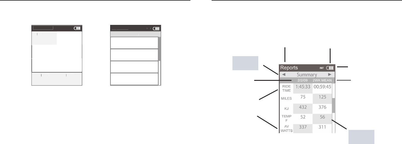
Title bar
Todays
Ride
Report
Type
Chapter 3: Reports Mode
Using Reports Mode
Joule 2.0 has four modes of operation: dashboard, reports, activities and menu indicated by the
title bar. Note: after the mode is displayed in the title bar for fi ve seconds, the time of day will be
displayed. Press and release [MODE] button to change from dashboard mode to report mode.
Better
Metric
Comparable
Timeframe
Report Metrics
Battery
indicator
Mode level
indicator
Chapter 2: Intervals
1. Intervals can be started at any point during the ride and from any mode. Press and release [INTERVAL]. To stop
the existing interval and start the next one, press and release [INTERVAL] again.
2. To view intervals from the dashboard press and hold [INTERVAL] until “INT” is displayed in the title bar. Note:
All dashboard data now pertains to the active interval only.
3. To exit interval mode, press and hold [INTERVAL] again. Note: all dashboard data will now pertain to the entire
ride.
4. To view all interval data press and release [MODE] to navigate to activities mode.
Note: Activities mode shows all intervals completed with the current interval at the top of the list. Average
power, heart rate, interval time and distance are displayed for each interval.
Intervals are disabled during saved workouts.
Intervals
Intervals may be viewed from activities mode or dashboard mode. Intervals are useful for view-
ing ride data specifi c to a section of your ride such as a hill or other period of high intensity
riding.
Inte
rv
al
s
Ac
tivities
4
168
w
182
hr
0:18:22
5.
1
mi
3
142
w
0:33:16
12.
3
mi
2
139
w
182
hr
0:30:04
9.
9
mi
1
11
9
w
170
hr
00:
11
:2
7
3.
4
mi
184
hr
IN
T
Dashboar
d
W/
W/
W/
KG
MX
W
AT
WAT
W
TS
AV
W
AV WAV
AT
WAT W
TS
212
876
402
402
5.2
MP
HC
HC
AD
27.4
98
MILES
FT GAIN
37.8
987
WA
TT
WATT
WA
S
IN
T
Joule 2.0 User Guide page 24
Joule 2.0 User Guide page 25
1. From dashboard mode, press and release [MODE] button. Press [JOYSTICK] left/right to change reports.
2. Press [JOYSTICK] up/down to scroll screen. Reports may also be accessed through History, see page 55.
3. Press in and release [JOYSTICK] to change date ranges from two weeks, four weeks, eight weeks, six months
and twelve months.
4. Move [JOYSTICK] left and right to show the other reports. There are eight available reports.
Using Reports Mode
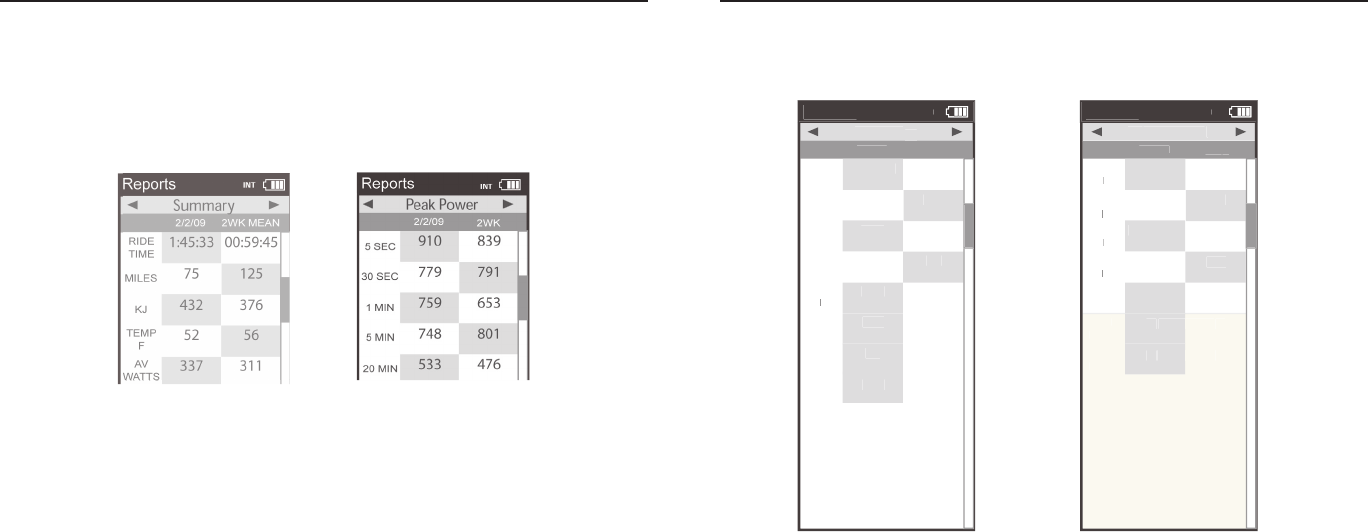
Joule 2.0 provides eight reports with an easy comparison of the current ride and historical aver-
ages so information can be seen in context. Each report contains three columns; the fi rst column
is the metric label, the second column is the data for a given metric on the current ride, the third
column is the average of all rides completed over the selected date range. Note: the highlighted
metrics represents the higher of the two metrics. For more information see Report Defi nitions for
an explanation of each metric in reports from pages 31-32.
Chapter 3: Reports Mode Chapter 3: Reports Mode
Report Details
Joule 2.0 provides eight reports that provide an easy comparison of the ride and historical aver-
ages so information can be seen in the context. For more information see Report Defi nitions for
an explanation of each metric in reports from pages 31-32.
2. In depth view of power specifi c
information for new insight into
ride intensity and characteristics.
Includes normalized power, watts
per kilogram of body weight and
time spent at zero watts.
1. Basic information with minimal
manipulation or calculation and
how they compare to previous
rides. Note: Ride time equals time
moving. Average watts is calcu-
lated without zeros and is time
weighted.
Reports
2/2/09
RIDE
TIME
AV
WA
TTS
WATTSWA
AV
CAD
2WK MEAN
Summa
ry
ry
MILE
S
75
125
KJ
432
376
337
311
TEM
P
F
52
56
105
94
AV
MP
H
22
20
AV
HR
167
165
1:45:33
00:59:45
IN
T
Reports
2/2/09
AV
WA
TTS
WATTS
WA
ZERO
WA
TTS
WATTS
WA
NP
2W
K
Po
wer Detai
l
MX
WA
TTS
WATTS
WA
478
641
ZERO
WA
TTS
WATTSWA
10%
6%
258
205
AV
W/KG
3.
12
12
.2
MX
W/KG
7.
35
35
.2
378
299
00:05:12
00:09:06
IN
T
Joule 2.0 User Guide page 26
Joule 2.0 User Guide page 27
Chapter 3: Reports Mode
Report Details
For more information see Report Defi nitions for an explanation of each metric in reports from
pages 31-32.
3. Key measures for quantify-
ing work completed, including
TrainingPeaks’ Training Stress
Score (TSS) and Intensity
Factor (IF).
4. Full array of peak power
data for indication of ride
intensity at key physiologi-
cal markers of current fi tness
compared to previous perfor-
mances.
Reports
2/2/09
KJ
2W
K
Wo
rk
KJ/H
R
289
482
TSS
3.
71
71
.0
IF
2.
03
03
.1
653
329
IN
T
Reports
2/2/09
5 SEC
5 MI
N
20 MI
N
2WK
P
eak
Po
we
r
30 SEC
779
791
1 MI
N
759
653
748
801
533
476
30 MI
N
512
419
40 MI
N
349
382
60 MI
N
291
196
910
839
IN
T
Chapter 3: Reports Mode
Report Details
For more information see Report Defi nitions for an explanation of each metric in reports from
pages 31-32.
5. Time spent in physiological
relevant power zones in abso-
lute minutes and as a percent
of total time.
6. Time spent in physiologi-
cal relevant heart rate zones
in absolute minutes and as
percent of total time.
Reports
2/2/09
1
4
5
2W
K
Time in P
ower Zones
2
00:20:22
00:24:51
3
00:44:16
00:49:23
01:00:29
01:01:44
00:13:34
00:12:31
6
00:08:03
00:05:01
1
10%
12%
2
15%
14%
3
30%
23%
4
41%
45%
5
12%
11%
6
3%
5%
00:15:04
00:12:33
IN
T
Reports
2/2/09
1
4
5
2W
K
Time in HR Z
one
s
2
00:05:09
00:09:4
5
3
00:49:03
00:35:1
4
00:19:58
00:15:3
2
00:05:02
00:03:2
1
1
11%
10%
2
9%
13%
3
70%
40%
4
21%
18%
5
6%
8%
00:09:51
00:07:3
1
IN
T

Joule 2.0 User Guide page 28
Joule 2.0 User Guide page 29
Chapter 3: Reports Mode
Report Details
For more information see Report Defi nitions for an explanation of each metric in reports from
pages 31-32.
7. Detailed indication of climbing in-
cluding total altitude gained and lost,
vertical ascent (VAM) and grade.
Note: climbing related data is only
functional when riding outdoors and is
subject to weather changes. See Techni-
cal Specifi cations on page 57.
8. Quantifi cation of how many
accelerations occured during a
ride over 4, 6, 8 and 10 watts per
kilogram. Note: A surge is count-
ed whenever three consecutive
values above a watt per kilogram
threshold are achieved.
Reports
2/2/09
FT
GAI
N
VA
M
2W
K
Climbing
Climbing
AV
GRADE
10%
15%
FT
LOST
226
112
349
509
2156
958
IN
T
Reports
2/2/09
>4
W/KG
>10
W/KG
2W
K
Surges
Surges
>6
W/KG
79
79
>8
W/KG
11
10
13
15
54
54
IN
T
Chapter 4: Reports Mode
Report Defi nitions
Summary Report
Ride Time
Time of ride defi ned as any time spent moving. Note: time spent stopped can be included if Joule Mode set-
tings are changed from speed record control to heart rate record control.
MI/KM
The ride length from start to fi nish measured in kilometers or miles.
KJ
1. 1000 Joules. 2. A unit of energy equal to the work done by a force of 1000 newtons acting through a distance
of 1 meter. 3. A measure of mechanical energy or the energy released when a force is applied to an object or
body. 4. A common unit used to express the total volume or work accomplished during a given workout, ride, or
exercise bout. 5. A unit or measure used to express the total training load. 6. The average power output in watts
multiplied by the time in seconds divided by 1000
TEMP C/F
The current temperature measured by Joule’s internal sensor.
AV WATTS
1. Average power during a ride. 2. A common unit used to express effort or intensity amongst cyclists. Note: Av-
erage calculation may or may not include zeros (time spent coasting or with no power) depending on Joule’s set
up. By default, zeros are included. For 2 WK, 4 WK rolling averages are time weighted over the selected period.
AV CAD
Average pedal revolutions per minute during a ride. Note: Average calculation may or may not include zeros
(time spent coasting or with no power) depending on Joule’s set up. By default, zeros are included. For 2 WK, 4
WK rolling averages a time weighted average over the selectable time period is used.
AV MPH/KPH
Average speed in miles per hour or kilometers per hour during a ride.
AV HR
Average heart rate in beats per minute during a ride. Note: For 2 WK, 4 WK rolling averages a time weighted
average over the selectable time period is used.

Joule 2.0 User Guide page 30
Joule 2.0 User Guide page 31
Chapter 4: Reports Mode
Report Definitions
Power Detail Report
AV WATTS
1. Average power during a ride. 2. A common unit used to express effort or intensity amongst cyclists. Note:
Average calculation may or may not include zeros (time spent coasting or with no power) depending on Joule’s
set up. By default, zeros are included. For 2 WK, 4 WK rolling averages a time weighted average over the select-
able time period is used.
MX WATTS
Maximum power in watts during a ride. Note: For 2 WK, 4 WK rolling averages a time weighted average over the
selectable time period is used.
ZERO WATTS
Cumulative ride time when Power is zero displayed in absolute minutes or as percentage of total ride time.
NORM POWER
An estimate of the power that you could have maintained for the same physiological “cost” if your power output
had been perfectly constant developed by Training Peaks.
AV W/KG
Average power in watts divided by rider weight in kg during a ride.
MX W/KG
Maximum power in watts divided by rider weight in kg during a ride.
Chapter 4: Reports Mode
Report Definitions
Work Report and Peak Power Report
KJ
1. 1000 Joules. 2. A unit of energy equal to the work done by a force of 1000 newtons acting through a distance
of 1 meter. 3. A measure of mechanical energy or the energy released when a force is applied to an object or
body. 4. A common unit used to express the total volume or work accomplished during a given workout, ride, or
exercise bout. 5. A unit or measure used to express the total training load. 6. The average power output in watts
multiplied by the time in seconds divided by 1000
KJ/HR
Average Kj’s per hour of riding during a ride
TSS
Training Stress Score estimating the total amount of glycogen burned on a ride.
IF
Ratio of the normalized power to threshold power. Joule uses the mid-point between the threshold zone (zone
3) and the race pace zone (zone 4) as the threshold power value.
Peak Power
The highest average power output that can be held for a given duration. 2. For most individuals a peak sustain-
able power or peak power output lasting 4 to 8 minutes is equivalent to an intensity that elicits their VO2 max,
or maximal capacity to consume oxygen. 3. For most individuals a peak sustainable power output lasting 20 to
40 minutes is equivalent to an intensity that elicits their lactate threshold or a value of blood lactate 2 to3 mM
above their baseline blood lactate. 4. For most individuals a peak sustainable power output lasting 40 minutes
to 2 hours is equivalent to an intensity that elicits their lactate threshold, or a value of blood lactate just above
to 1 mM above their baseline blood lactate. 5. In cycling, the peak sustainable power for any given duration
is analogous to their best performance for a given time. For example, a runner might have a personal best of
5 minutes in a mile run and 35 minutes in a 10 km run, whereas a cyclist might have a personal best or peak
sustainable power of 400 watts for 5 minutes and 340 watts for 35 minutes.

Joule 2.0 User Guide page 32
Joule 2.0 User Guide page 33
Chapter 4: Reports Mode
Report Definitions
Time in Zones Report
Training Zones
1. Discrete bins or intervals specific to a particular energy or physiological system. From short maximal efforts
to long maximal efforts these energy systems run along a continuum from anaerobic to aerobic metabolic
pathways. Common reference points for this continuum include the power at lactate threshold and power at
VO2 max.
Recovery Zone (Zone 1)
1. An easy exercise intensity where there is minimal stress or strain on the body. 2. On a 1 to 10 rating of per-
ceived exertion scale, the recovery zone corresponds to a 1 to 2 or “really easy” to “easy”. 3. On a 6 to 20 rating
of perceived exertion scale, the recovery zone corresponds to a 6 to 10 or “very very light” to “very light.” 4. An
exercise intensity dependent solely on aerobic metabolism of primarily fat. 5. An exercise intensity that can be
held for an indefinite time frame.
Endurance Zone (Zone 2)
1. A moderate exercise intensity where there is some stress or strain on the body 2. On a 1 to 10 RPE scale,
an intensity corresponding to 3 to 4 or “moderate” to “sort of hard”. 3. On a 6 to 20 RPE scale, an intensity cor-
responding to a 10 to 13 or “fairly light” to “somewhat hard.” 4. An exercise intensity depending on the aerobic
metabolism of both fat and carbohydrate. 5. An exercise intensity that can be held as long as the athlete were
supplied with an influx of carbohydrate (i.e., allowed to eat).
Lactate Threshold (LT) Zone (Zone 3)
1. A hard intensity zone marked by a sudden increase in breathing rate. 2. On a 1 to 10 RPE scale, an intensity
corresponding to a 5 to 7 or “hard” to “really hard.” 3. On a 6 to 20 RPE scale, an intensity corresponding to a 13
to 16 or “somewhat hard” to “very hard”. 4. A range of exercise intensity beginning at a slight inflection or rise in
the blood lactate over a resting baseline to an intensity corresponding with a blood lactate 2 to 3 mM above a
resting baseline. 5. A demarcation between aerobic metabolism to a mix of anaerobic and aerobic metabolism.
6. An all out exercise intensity that can be held between 40 minutes to 2 hours depending on the availability of
stored carbohydrate or glycogen within the body.
Chapter 4: Reports Mode
Report Definitions
Time in Zones Report...continued
Race Pace Zone (Zone 4)
1. An extremely hard or all out intensity zone. 2. On a 1 to 10 RPE scale, an intensity corresponding to a 7 to 8
or “really hard” to “really really hard.” 3. On a 6 to 20 RPE sale, an intensity corresponding to a 16 to 18 or “very
hard” to “very very hard.” 4. An exercise intensity dependent primarily on the aerobic and anaerobic metabolism
of carbohydrate. 5. An all out exercise intensity that can be held between 10 minutes to 30 minutes.
Max Zone (Zone 5)
1. An all out or maximal intensity zone. 2. On a 1 to 10 RPE scale, an intensity corresponding to a 9 to 10 or “really
really hard” to “maximal.” 3. On a 6 to 20 RPE scale, an intensity corresponding to an 18 to 20, or “very very hard”
to “maximal.” 4. An exercise intensity that elicits the causes the body to reach its maximal capacity to consume
oxygen (i.e., an exercise intensity that elicits VO2 max). 5. An all out or maximal effort that can be held between
2 to 8 minutes or an average of 4 minutes.
Supra-Max Zone (Zone 6)
1. A very short, all out effort that exceeds the power output associated with VO2 max or a person’s max zone. 2.
An exercise intensity that is almost entirely dependent on the anaerobic metabolism of stored ATP, Phospha-
gens, and carbohydrates. 3. An all out effort lasting 1 second to 2 minutes.

Joule 2.0 User Guide page 34
Joule 2.0 User Guide page 35
Chapter 4: Reports Mode
Report Defi nitions
Climbing and Surges Report
M/FT GAIN
The total vertical distance in feet or meters traveled or climbed over a given distance ridden.
AV% GRADE
The rise or vertical increase in elevation divided by the run or horizontal distance traveled multiplied by 100
(rise ÷ run x 100).
M/FT LOST
The total vertical distance in feet or meters descended over a given distance ridden.
VAM
1. The rate of vertical ascent in meters per hour. Note: At an 8% grade, a rate of ascent of 1800 meters per hour
requires a power output of 6.3 watts per kg and is considered the upper limit for climbing speed in professional
cyclists.
Surges
A surge is a sudden, short acceleration lasting a minimum of 3 seconds within a particular w/kg zone. The value
is simply displayed as the number of times this occurs per watts/kg zone. Once a surge is recorded in a w/kg
zone, the w/kg value must drop at least 0.1 w/kg below the minimum zone value before a positive increase in
value back into that zone can be considered a new surge.
Title bar
Customizable
Metrics
Activities
Type
Using Activities Mode
Joule 2.0 has four modes of operation: dashboard, reports, activities and menu indicated by the
title bar. Note: after the mode is displayed in the title bar for fi ve seconds, the time of day will be
displayed. Press and release [MODE] button to change from dashboard mode to report mode to
activites mode.
Upcoming Segments
Manual
Wo
rkout
4:38P
TR
G
PWR
300
300
WA
TT
WATT
WA
S
289
Current:6
01:42:23
2999w
250b
999.9m
i
Interval:5
01:42:23
2999w
250b
999.9m
i
Interval:4
01:42:23
2999w
250b
999.9m
i
Interval:3
01:42:23
2999w
250b
999.9m
i
Battery
indicator
Interval
On/Off
Mode level
indicator
Chapter 5: Workouts

Joule 2.0 User Guide page 36
Joule 2.0 User Guide page 37
Using Workouts
Joule 2.0 offers two types of workouts, manual and saved, each managed in the Activities Mode.
Manual workouts may only be performed with a CycleOps 400 Pro indoor cycle or PowerBeam
Pro trainer. Saved workotus are created using PowerAgent software and transferred to Joule 2.0
Both workout types are helpful for making sure a specifi c workout plan is followed by displaying
the workout in a series of segments with target intenisty and rest indicated.
Chapter 5: Workouts
Using Manual Workouts with CycleOps 400 Pro Indoor Cycle
The controlled resistance technology offered on the CycleOps 400 Pro indoor cycle allows workout
intensity to be precisely managed by targeting slope or a specifi c power output.
Sensor
s
>
Setup Joule
>
Setup User
>
Wo
rkout
s
>
Hist
or
y
>
Sensor
s
>
Main
>
Exit Menu
<
Menu
Menu
Main
Hill
Wo
rkout
Ac
tivities
10%
WA
TT
WATTWA
S
2999
Current Segment:6 00:42:23
10%
250b
999.9m
i
Segment:5
01:42:23
8%
250b
999.9m
i
Segment:4
01:42:23
7%
250b
999.9m
i
Segment:3
01:42:23
15%
250b
999.9m
i
Chapter 5: Workouts
Workouts can be ridden in dashboard mode and activities mode.
1. Press and release [MODE] until Menu mode is displayed.
2. Press [JOYSTICK] up/down to highlight Workouts. Press [JOYSTICK] in and release to select Workouts.
3. If Joule 2.0 has been paired to the 400 Pro resistance unit a manual workout will be started automatically once
the resistance unit is found by Joule 2.0. For more information on pairing and fi nding sensors please refer to
page 56. It is also possible to select manual workout by selecting workouts from Menu mode and then manual
workout.
4. Press [JOYSTICK] up/down to adjust the target power from any mode once a manual workout is started in 10
watt increments from 30 watts to 1000 watts. Note: The 400 Pro will automatically adjust the resistance to match
the target power output. Power is a combination of speed and torque. Because of this, you experience less resis-
tance the faster you pedal, keeping your power output at the targeted level. Not all power levels are available at
all speeds. When the 400 Pro cannot add any more resistance, you should speed up to achieve the target power.
When the 400 Pro cannot remove any more resistance you should slow down to achieve the target power.
Joule 2.0 User Guide page 38
Joule 2.0 User Guide page 39
Using Manual Workouts with CycleOps 400 Pro Indoor Cycle...continued
Gear Ratios
Hill
Wo
rkout
Ac
tivities
R
S
P
10%
WA
TT
WATT
WA
S
2999
Current Segment:6 00:42:23
10%
250b
999.9m
i
Segment:5
01:42:23
8%
250b
999.9m
i
Segment:4
01:42:23
7%
250b
999.9m
i
Segment:3
01:42:23
15%
250b
999.9m
i
Chapter 5: Workouts
Using Manual Workouts with CycleOps PowerBeam Pro Trainer
The controlled resistance technology offered on the CycleOps PowerBeam Pro trainer allows
workout intensity to be precisely managed by targeting slope or a specifi c power output.
Manual
Wo
rkout
>
Select
W
orkout
Workout W
Back
<
3:16p
Wo
rkout
s
Manual
Wo
rkout
4:38P
TR
G
PWR
G
PWR
G
300
300
WA
TT
WATTWA
S
289
Current:6
01:42:23
2999w
250b
999.9m
i
Interval:5
01:42:23
2999w
250b
999.9m
i
Interval:4
01:42:23
2999w
250b
999.9m
i
Interval:3
01:42:23
2999w
250b
999.9m
i
Chapter 5: Workouts
Chainring Sprocket Display Gear Diffi culty
50 10 1 Hardest
53 11 2 Harder
50 11 3 Harder
50 12 4 Harder
50 13 5 Harder
50 14 6 Harder
50 15 7 Harder
50 11 8 Harder
34 17 9 Harder
50 12 10 Harder
34 19 11 Harder
34 14 12 Easier
50 15 13 Eaiser
34 23 14 Easier
34 17 15 Easier
34 19 16 Easier
34 21 17 Easier
34 23 18 Easier
34 25 19 Easier
34 27 20 Easier
34 30 21 Easier
34 34 22 Easiest
5. Press [JOYSTICK] in and release to change the resistance type from target power to target slope. Slope
measures grade steepness of your simulated climb. You can choose a grade between 0 and 25. The higher the
number, the steeper the slope you’re climbing. While in slope mode, the 400 Pro provides the resistance for the
selected slope at whatever speed you’re riding. The faster you pedal, the more resistance you’ll need to over-
come, just like riding up an actual hill. The resistance the 400 Pro simulates is calculated considering the power
needed to climb the target slope on a road bike with slick tires and the user weight saved in Joule’s User Setup.
For information on setting up user weight see pages 66-67 or connect Joule to PowerAgent software to adjust
user weight.
6. Press [JOYSTICK] in and release again to change from target slope to gearing. The gearing setting uses the
previously set target slope but allows you to change the gear ratio simulated by the 400 Pro. This is useful for
understanding what gear combination is best for you on various slopes so you can train for your goal terrain.
The gears and ratios simulated by the 400 Pro are listed above:
7. Press and release [INTERVAL] at anytime during a manual workout to start a new interval and end a previous
interval. To review intervals during a manual workout, press [MODE] to navigate to Activities Mode and then
pess the [JOYSTICK] left/right to highlight the intervals then press [JOYSTICK] up/down to scroll list.
1. Press and release [MODE] until Menu mode is displayed.
2. Press [JOYSTICK] up/down to highlight Workouts. Press [JOYSTICK] in and release to select Workouts.
3. If Joule 2.0 has been paired to the PowerBeam Pro resistance unit a manual workout will be started automati-
cally once the resistance unit is found by Joule 2.0 and speed is detected. For more information on pairing and
fi nding sensors please refer to pages 48-54.
4. Press the [JOYSTICK] up/down to adjust the target power from any mode once a manual workout is started
in 10 watt increments from 30 watts to 1000 watts. Note: The PowerBeam Pro will automatically adjust the
resistance to match the target power output. Power is a combination of speed and torque. Because of this, you
experience less resistance the faster you pedal, keeping your power output at the targeted level. Not all power
levels are available at all speeds.
5. When the PowerBeam Pro cannot add any more resistance, you should speed up to achieve the target power.
When the PowerBeam Pro cannot remove any more resistance you should slow down to achieve the target
power.
Joule 2.0 User Guide page 40
Joule 2.0 User Guide page 41
Using Manual Workouts with CycleOps PowerBeam Pro Trainer...continued
Manual
Wo
rkout
>
Select
W
orkout
Workout W
Back
<
3:16p
Wo
rkout
s
Manual
Wo
rkout
4:38P
TR
G
PWR
G
PWR
G
300
300
WA
TT
WATTWA
S
289
Current:6
01:42:23
2999w
250b
999.9m
i
Interval:5
01:42:23
2999w
250b
999.9m
i
Interval:4
01:42:23
2999w
250b
999.9m
i
Interval:3
01:42:23
2999w
250b
999.9m
i
Chapter 5: Workouts
6. Press [JOYSTICK] in and release to change the resistance type from target power to target slope. Slope mea-
sures grade steepness of your simulated climb. You can choose a grade between 0 and 10 for the slope. The
higher the number, the steeper the slope you’re climbing. While in slope mode, the PowerBeam Pro provides
the resistance for the selected slope at whatever speed you’re riding. The faster you pedal, the more resistance
you’ll need to overcome, just like riding up an actual hill. The resistance the PowerBeam Pro simulates is calcu-
lated considering the power needed to climb the target slope on a road bike with slick tires and the user weight
saved in Joule’s User Setup. For information on setting up user weight see pages 66-67 or connect Joule to
PowerAgent software to adjust user weight.
7. Shift gears on your bicycle to adjust the intensity at the target slope.
8. Press in and release INTERVAL] at anytime during a manual workout to start a new interval and end a previous
interval. To review intervals during a manual workout, press [JOYSTICK] left/right to highlight the intervals then
press [JOYSTICK] up/down to scroll list.
Using Saved Workouts with CycleOps 400 Pro Indoor Cycle
Workouts may be created in PowerAgent software and saved to Joule for use on the 400 Pro
indoor cycle. The advantage of saved workouts over manual workouts is that the resistance will
change automatically based on the saved time or distance of each segment. This is helpful for du-
plicating a specifi c course you are training for. Note: Resistance target and type can be changed
during a ride in a saved workout in the same way as a manual workout.
Chapter 5: Workouts
1. Press and release [MODE] until Menu mode is displayed.
2. Press [JOYSTICK] up/down to highlight Workouts. Press [JOYSTICK] in and release to select Workouts.
3. Press [JOYSTICK] up/down to highlight the desired saved workout. Press [JOYSTICK] in and release to select
the desired saved workout.
4. Once the saved workout is selected, Joule 2.0 will display activities mode and the segments associated with
the saved workout. The fi rst segment of the workout will begin as soon as pedaling begins.
5. Pressing [JOYSTICK] up/down adjusts the target resistance from any mode once a saved workout is started.
Note: The 400 Pro will automatically adjust the resistance to match the target resistance from the saved work-
out. Power is a combination of speed and torque. Because of this, you experience less resistance the faster you
pedal, keeping your power output at the targeted level. Not all power levels are available at all speeds. When
the 400 Pro cannot add any more resistance, you should speed up to achieve the target power. When the 400
Pro cannot remove any more resistance you should slow down to achieve the target power.
Manual
Wo
rkout
>
Select
W
orkout
Workout W
Back
<
3:16p
Wo
rkout
s
Hill
Wo
rkout
Ac
tivities
R
S
P
10%
WA
TT
WATT
WA
S
2999
Current Segment:6 00:42:23
10%
250b
999.9m
i
Segment:5
01:42:23
8%
250b
999.9m
i
Segment:4
01:42:23
7%
250b
999.9m
i
Segment:3
01:42:23
15%
250b
999.9m
i

Joule 2.0 User Guide page 42
Joule 2.0 User Guide page 43
Using Saved Workouts with CycleOps PowerBeam Pro Trainer
Workouts may be created in PowerAgent software and saved to Joule for use on the PowerBeam
Pro trainer. The advantage of saved workouts over manual workouts is that the resistance will
change automatically based on the saved time or distance of each segment created in Power-
Agent software. This is helpful for duplicating a specifi c course you are training for. Note: Resis-
tance target and type can be changed in a saved workout in the same way as a manual workout.
Manual
Wo
rkout
>
Select
W
orkout
Workout W
Back
<
3:16p
Wo
rkout
s
Hill
Wo
rkout
Ac
tivities
R
S
P
10%
WA
TT
WATT
WA
S
2999
Current Segment:6 00:42:23
10%
250b
999.9m
i
Segment:5
01:42:23
8%
250b
999.9m
i
Segment:4
01:42:23
7%
250b
999.9m
i
Segment:3
01:42:23
15%
250b
999.9m
i
Chapter 5: Workouts
Using Saved Workouts with CycleOps 400 Pro Indoor Cycle...continued
Chapter 5: Workouts
Slope measures grade steepness of your simulated climb. You can choose a grade between 0 and 25 for the
slope. The higher the number, the steeper the slope you’re climbing. While in slope mode, the 400 Pro provides
the resistance for the selected slope at whatever speed you’re riding. The faster you pedal, the more resistance
you’ll need to overcome, just like riding up an actual hill. The resistance the 400 Pro simulates is calculated con-
sidering the power needed to climb the target slope on a road bike with slick tires and the user weight saved in
Joule’s User Setup. For information on setting up user weight see pages 66-67 or connect Joule to PowerAgent
software to adjust user weight.
6. Press [JOYSTICK] in and release to change from target slope to gearing. The gearing setting uses the previ-
ously set target slope but allows you to change the gear ratio simulated by the 400 Pro. This is useful for un-
derstanding what gear combination is best for you on various slopes so you can train for your goal terrain. The
gears and ratios simulated by the 400 Pro are listed on page 40.
7. When a saved workout is completed each saved segment is automatically converted to an interval. Press
[JOYSTICK] left/right to highlight the intervals. Press [JOYSTICK] up/down to scroll up/down and review the
intervals. Note: when a saved workout is completed the target resistance defaults to 100 watts. Note: Intervals
are disabled during while riding saved workouts.
1. Press and release [MODE] until Menu mode is displayed.
2. Press [JOYSTICK] up/down to highlight Workouts. Press [JOYSTICK] in and release to select Workouts.
3. Press [JOYSTICK] up/down to highlight the desired saved workout. Press [JOYSTICK] in and release to select
the desired saved workout.
4. Once the saved workout is selected, Joule 2.0 will display Activities Mode and the segments associated with
the saved workout. The fi rst segment of the workout will begin as soon as pedaling begins.
5. Pressing [JOYSTICK] up/down adjusts the target resistance from any mode once a saved workout is started
Note: The PowerBeam Pro will automatically adjust the resistance to match the target power output. Power is a
combination of speed and torque. Because of this, you experience less resistance the faster you pedal, keeping
your power output at the targeted level. Not all power levels are available at all speeds. When the PowerBeam
Pro cannot add any more resistance, you should speed up to achieve the target power. When the PowerBeam
Pro cannot remove any more resistance you should slow down to achieve the target power.
Joule 2.0 User Guide page 44
Joule 2.0 User Guide page 45
Using Saved Workouts with CycleOps PowerBeam Pro Trainer...continued
Manual
Wo
rkout
>
Select
W
orkout
Workout W
Back
<
3:16p
Wo
rkout
s
Hill
Wo
rkout
Ac
tivities
R
S
P
10%
WA
TT
WATT
WA
S
2999
Current Segment:6 00:42:23
10%
250b
999.9m
i
Segment:5
01:42:23
8%
250b
999.9m
i
Segment:4
01:42:23
7%
250b
999.9m
i
Segment:3
01:42:23
15%
250b
999.9m
i
Chapter 5: Workouts
Slope measures grade steepness of your simulated climb. You can choose a grade between 0 and 10 for the
slope. The higher the number, the steeper the slope you’re climbing. While in slope mode, the PowerBeam
Pro provides the resistance for the selected slope at whatever speed you’re riding. The faster you pedal, the
more resistance you’ll need to overcome, just like riding up an actual hill. The resistance the PowerBeam Pro
simulates is calculated considering the power needed to climb the target slope on a road bike with slick tires
and the user weight saved in Joule’s User Setup. For information on setting up user weight see pages 66-67 or
connect Joule to PowerAgent software to adjust user weight.
6. Shift gears on your bicycle to adjust the intensity at the target slope.
7. When a saved workout is completed each saved segment is automatically converted to an interval. Press
[JOYSTICK] left/right to highlight the intervals. Press [JOYSTICK] up/down to scroll up/down and review the
intervals. Note: when a saved workout is completed the target resistance defaults to 100 watts. Note: Intervals
are disabled during while riding saved workouts.
Pausing, Saving or Deleting a Workout
A workout, like any ride can be paused, saved or deleted.
1. Press and hold [MODE] button to access Ride Paused screen.
2. Press [JOYSTICK] up/down to highlight Pause, Stop and Save or Stop and Delete workout. Press [JOYSTICK]
in and release to save changes.
Note: there will be a confi rmation screen before deleting a ride. Stop and save will stop the workout and save it
to History.
>
Resume rid
e
>
>
>
>
Stop and Save
>
Stop and Delete
>
12:02p
IN
T
Ride P
aused
Inte
rv
al
s
Ac
tivities
R
PWR
300
300
WA
TT
WATTWA
S
289
Current:6
01:42:23
2999w
250b
999.9m
i
Interval:5
01:42:23
2999w
250b
999.9m
i
Interval:4
01:42:23
2999w
250b
999.9m
i
Interval:3
01:42:23
2999w
250b
999.9m
i
IN
T
Chapter 5: Workouts

Joule 2.0 User Guide page 46
Joule 2.0 User Guide page 47
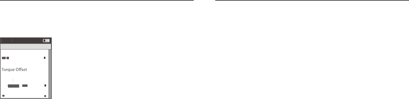
1. Press and release the [MODE] button until Menu mode is displayed.
2. Press [JOYSTICK] in and release to select Sensors.
3. Press [JOYSTICK] in and release to select Power Sensor.
4. Press [JOYSTICK] up/down to highlight the desired Sensor Type. For CycleOps PowerTap Plus series hubs
press [JOYSTICK] in and release to select Add PowerTap. For CycleOps Pro Series indoor cycles select Add IC
Power. For any ANT+ compatible power sensor select Add ANT+.
5. Make sure the power sensor is awake and isolated from other active sensors by 65 feet/20 meters. For Power-
Tap and IC Power sensors rotate the hub/wheel at least one revolution. For ANT+ sensors see that sensor’s user
guide for information on waking up the sensor.
6. Press the [JOYSTICK] in and release to Start Pairing. Pairing may take up to 60 seconds. Once pairing is suc-
cessful, the sensor ID will be displayed.
7. Press [JOYSTICK] up/down to highlight Name. Press [JOYSTICK] in and release to select name and change the
name of the paired power sensor.
8. For PowerTap sensors only, press [JOYSTICK] up/down to highlight the wheel circumference and press [JOY-
STICK] in and release to select wheel circumference. Press [JOYSTICK] up/down to change wheel circumference.
Press JOYSTICK in and release to save changes. For a list of common wheel circumferences see FAQ section.
Chapter 6: Sensors
Setting Up Power Sensors
Joule 2.0 is compatible with many ANT+ sensors, each having a unique code. A sensor is defined
as any ANT + compatible power meter, cadence sensor, speed sensor, heart rate strap and
CycleOps resistance unit. Joule 2.0 needs to be paired to each sensor to ensure proper function-
ality. Common CycleOps power sensors include the PowerTap hub, 300 Pro and 400 Pro indoor
cycles. Once set up, sensors can be managed using PowerAgent software. Note: if you purchased
a CycleOps 200 Pro, 300 Pro, 400 Pro indoor cycle or PowerBeam trainer all available sensors have
been paired at the factory.
Setting Up Power Sensors...continued.
9. Press [JOYSTICK] up/down to highlight Auto Zero Yes or No. Press [JOYSTICK] in and release to select Auto
Zero Yes or No. Press [JOYSTICK] up/down to change Auto Zero Yes or No. Note: Auto Zero setting should
remain set to Yes in all cases except when using a Track PowerTap.
10. Press [JOYSTICK] up/down to highlight Activate Sensor.
11. Press [JOYSTICK] in and release to Activate Sensor. Note: active sensor is designated by a hash mark next to
the sensor name in the sensor list. When switching speed sensors, be sure to activate the appropriate sensor.
12. Once a sensor has been paired and activated Joule 2.0 will automatically find the active sensor whenever it
is turned on.
Note: multiple sensors can be stored by Joule 2.0 but only one can be active per sensor category at a given time.
Chapter 6: Sensors
Joule 2.0 User Guide page 48
Joule 2.0 User Guide page 49
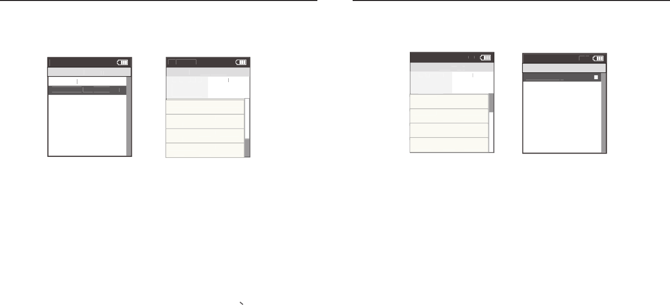
1. Press and release the [MODE] button until Menu mode is displayed.
2. Press [JOYSTICK] in and release to select Sensors.
3. Press [JOYSTICK] in and release to select Power Sensor.
4. Press [JOYSTICK] up/down to highlight the Active Sensor. Press [JOYSTICK] in
and release to select the Active Sensor. Note active sensor is designated by a
hash mark next to the sensor name in the sensor list.
5. Make sure the power sensor is awake. For PowerTap and IC Power sensors
rotate the hub/wheel at least one revolution. For ANT+ sensors see that sensor’s
user guide for information on waking up the sensor.
6. Press [JOYSTICK] up/down to highlight Manual Zero. Press [JOYSTICK] in and
release to select Manual Zero.
7. The raw torque value, offset and fi rmware version will be shown. If the raw
value and offset value does not match a manual zero should be performed.
8. Press [JOYSTICK] up/down to highlight Manual Zero. Press [JOYSTICK] in and
release to perform Manual Zero.
Power Sensor Manual Zero
Like a kitchen scale, it is possible for power sensors to incur an offset that needs to be zeroed. This
can happen due to large temperature changes which effect the material the power sensors are
attached to and often results in power being displayed even while coasting.
Chapter 6: Sensors
Setting up Cadence Sensors
Joule 2.0 is compatible with many ANT+ cadence sensors, each having a unique code. A sensor is
defi ned as any ANT + compatible power meter, cadence sensor, speed sensor, heart rate strap and
CycleOps resistance unit. Joule 2.0 needs to be paired to each sensor to ensure proper functional-
ity. Once set up, sensors can be managed using PowerAgent software. Note: some power sensors
do not require a separate cadence sensor in order to display cadence data.
1. Press and release the [MODE] button until Menu mode is displayed.
2. Press [JOYSTICK] in and release to select Sensors.
3. Press [JOYSTICK] in and release to select Cadence Sensor.
4. Press [JOYSTICK] up/down to highlight Add New Sensor. Press [JOYSTICK] in and release to select Add New
Sensor.
5. Make sure the power sensor is awake and isolated from other active sensors by 65 feet/20 meters. Rotate the
crank to wake up the cadence sensor.
6. Press the [JOYSTICK] in and release to Start Pairing. Pairing may take up to 60 seconds. Once pairing is suc-
cessful, the sensor ID will be displayed.
7. Press [JOYSTICK] up/down to highlight Name. Press [JOYSTICK] in and release to select Name and change
the name of the paired power sensor. Press [JOYSTICK] in and release to save changes.
8. Press [JOYSTICK] up/down to select Activate Sensor. Press [JOYSTICK] in and release to Activate Sensor.
Note: The active sensor is designated by a hash mark next to the sensor name in the sensor list. When switch-
ing cadence sensors, be sure to activate the appropriate sensor.
9. Once a sensor has been paired and activated Joule 2.0 will automatically fi nd the active sensor whenever it is
turned on.
Chapter 6: Sensors
Manual
Ze
ro
>
X
X
>
To
X
To
X
rque R
rque R
Xrque R
X
X
rque R
X
AW
>
>
>
>
SEARCHING
>
To
r
que O
set
>
Manual C
alibration
>
To
r
que O
set
>
Pa
To
Pa
To
ir
r
ir
r
que O
ir
que O
>
>
>
>
>
>
>
>
Bac
k
>
k
>
<
To
<
To
Menu
Calibration
>
SEARCHING
>
Hub
V
ersion
Version V
>
SEARCHING
r SEARCHING
r
que O
SEARCHING
que O
SEARCHING
set
SEARCHING
set
ir
SEARCHING
ir
r
ir
r SEARCHING
r
ir
r
que O
ir
que O
SEARCHING
que O
ir
que O
>
>
>
>
>
>
>
>
>
>
>

Joule 2.0 User Guide page 50
Joule 2.0 User Guide page 51
Setting Up Speed Sensors
Joule 2.0 is compatible with ANT+ speed sensors, each having a unique code. Joule 2.0 needs to
be paired to each sensor to ensure proper functionality. Once set up, sensors can be managed
using PowerAgent software.
1. Press and release the [MODE] button until Menu mode is displayed.
2. Press [JOYSTICK] in and release to select Sensors.
3. Press [JOYSTICK] up/down to highlight Speed Sensor. Press [JOYSTICK] in and release to select Speed
Sensor.
4. Press [JOYSTICK] up/down to highlight Add New Sensor. Press [JOYSTICK] in and release to select Add New
Sensor.
5. Make sure the Speed Sensor is awake and isolated from other active sensors by 65 feet/20 meters. Note: For
most Speed Sensors, rotating the wheel will wake up the sensor.
6. Press the [JOYSTICK] in and release to Start Pairing. Pairing may take up to 60 seconds. Once pairing is suc-
cessful, the sensor ID will be displayed.
7. Press [JOYSTICK] up/down to highlight Name. Press [JOYSTICK] in and release to select Name and change
the name of the paired speed sensor. Press [JOYSTICK] in and release to save changes.
8. Press [JOYSTICK] up/down to highlight the Wheel Circumference and press [JOYSTICK] in and release to
select wheel circumference. For a list of common wheel circumferences see FAQ section.
9. Press [JOYSTICK] up/down to highlight Activate Sensor. Press [JOYSTICK] in and release to Activate Sensor.
Note: active sensor is designated by a hash mark next to the sensor name in the sensor list. When switching
speed sensors, be sure to activate the appropriate sensor.
10. Once a sensor has been paired and activated Joule 2.0 will automatically find the active sensor whenever it
is turned on.
Chapter 6: Sensors
Setting Up Heart Rate Sensors
Joule 2.0 is compatible with ANT+ heart rate sensors, each having a unique code. Joule 2.0 needs
to be paired to each sensor to ensure proper functionality. Once set up, sensors can be managed
using PowerAgent software.
1. Press and release the [MODE] button until Menu mode is displayed.
2. Press [JOYSTICK] in and release to select Sensors.
3. Press [JOYSTICK] up/down to highlight Heart Rate Sensor. Press [JOYSTICK] in and release to select Heart
Rate Sensor.
4. Press [JOYSTICK] up/down to highlight Add New Sensor. Press [JOYSTICK] in and release to select Add New
Sensor.
5. Make sure the Heart Rate Sensor is being worn and isolated from other active sensors by 65 feet/20 meters.
6. Press the [JOYSTICK] in and release to Start Pairing. Pairing may take up to 60 seconds. Once pairing is suc-
cessful, the sensor ID will be displayed.
7. Press [JOYSTICK] up/down to highlight Name. Press [JOYSTICK] in and release to select Name and change
the name of the paired heart rate sensor. Press [JOYSTICK] in and release to save changes.
8. Press [JOYSTICK] up/down to highlight Activate Sensor. Press [JOYSTICK] in and release to Activate Sensor.
Note: active sensor is designated by a hash mark next to the sensor name in the sensor list. When switching
heart rate sensors, be sure to activate the appropriate sensor.
9. Once a sensor has been paired and activated Joule 2.0 will automatically find the active sensor whenever it is
turned on.
Chapter 6: Sensors

Joule 2.0 User Guide page 52
Joule 2.0 User Guide page 53
Setting Up Resistance Unit Sensors
Joule 2.0 is compatible with CycleOps electronic resistance units (RU) found on the CycleOps
400 Pro indoor cycle and PowerBeam Pro trainer. In order to be paired, CycleOps electronic
resistance units need to be set for pairing by unplugging them for 5 seconds and the plugging
them back in.
1. Press and release the [MODE] button until Menu mode is displayed.
2. Press [JOYSTICK] in and release to select Sensors.
3. Press [JOYSTICK] up/down to highlight RU Sensor. Press [JOYSTICK] in and release to select RU Sensor.
4. Press [JOYSTICK] up/down to highlight Add New Sensor. Press [JOYSTICK] n and release to select Add New
Sensor.
5. Make sure the RU sensor has been unplugged and plugged back in in the last 30 seconds.
6. Press the [JOYSTICK] in and release to Start Pairing. Pairing may take up to 60 seconds. Once pairing is suc-
cessful, the sensor ID will be displayed.
7. Press [JOYSTICK] up/down to highlight Name. Press [JOYSTICK] in and release to select name and change
the name of the paired RU sensor. Press [JOYSTICK] in and release to save changes.
8. Press [JOYSTICK] up/down to highlight Activate Sensor. Press [JOYSTICK] in and release to Activate Sensor.
Note: active sensor is designated by a hash mark next to the sensor name in the sensor list. When switching RU
sensors, be sure to activate the appropriate sensor.
9. Once a sensor has been paired and activated Joule 2.0 will automatically find the active sensor whenever it is
turned on.
Chapter 6: Sensors Chapter 7: Setting Up CycleOps Joule 2.0
Manual Calibration for CycleOps PowerBeam Pro Trainer
If you use a power meter such as the PowerTap, you can perform a manual calibration to more
accurately calibrate your CycleOps PowerBeam Pro trainer. Note: the power meter must be paired
to Joule 2.0 prior to performing the manual calibration.
1. Before entering the calibration routine,
warm up the PowerBeam Pro and tires by
riding the system for five minutes.
2. Press and release the [MODE] button
until Menu mode is displayed.
3. Press [JOYSTICK] in and release to
select Sensors.
4. Press [JOYSTICK] up/down to highlight
RU Sensor. Press [JOYSTICK] in and
release to select RU Sensor.
5. Press [JOYSTICK] up/down to highlight
the active RU Sensor. Note: the active
RU Sensor is indicated by a hash mark next to the name in the RU Sensor list. Press [JOYSTICK] in and release to
select the active RU Sensor.
6. Press [JOYSTICK] up/down to highlight Calibration. Press [JOYSTICK] up/down to select Calibration.
7. Press [JOYSTICK] up/down to highlight Manual Calibration. Press [JOYSTICK] in and release to select Manual
Calibration.
8. Joule 2.0 will show the measured power using the current rolling resistance calibration.
9. Pedal at a constant speed to stabilize the resistance. Target 20 mph and press [JOYSTICK] up/down to change
the calibration until the displayed power matches the measured power.
10. When the two values match, press [JOYSTICK ].
11.The unique rolling resistance calibration is now incorporated into the factory calibration. This calibration will
remain in the system until another calibration is performed. Note: The Roll Down Calibration and the Manual
Calibration adjust the same calibration values. Only the last calibration values are saved.
OK >
Name: >
12345 >
12345 >
Weight - lbs: >
12.1 >
Wheel Circumference:>
1234 >
Auto Zero (Y or N): >
Y>
>
Auto Zero (Y or N):
>
Cervelo >
Sensor ID: >
12345 >
Calibration >
ERU Data>
Re-Pair Sensor
>
>
Delete Sensor >
Delete Sensor >
Delete Sensor >
Delete Sensor >
Delete Sensor >
Delete Sensor >
Delete Sensor >
Delete Sensor >
Delete Sensor >
Delete Sensor >
Back
<
Report
Menu
INT
PowerBeam1
Scenerio:
ERU Calibration
Roll Down >
Manual >
Reset to Defaults >
Sensor ID
Sensor ID
The Gun Show >
Torque Offset >
Manual Calibration >
Torque Offset >
Back
<
Report
Menu
INT
Calibration
Power Sensor: 9999 w >
>
Roll Down Calibration
Wheel Circumference >
Wheel Circumference >
The Gun Show >
Auto Zero>
Auto Zero>
Pair >
Roll Down >
Manual >
Reset to Defaults >
Sensor ID
Sensor ID
The Gun Show >
Torque Offset >
Manual Calibration >
Torque Offset >
Pair New Sensor >
Back
<
Report
Menu
INT
Calibration
Pedal to 18-22 MPH >
XX
Hold for (sec):
XXX
Current Speed:
XX.X >
Torque Offset >
Manual Calibration >
Torque Offset >
Pair >
Completed >
Back
<
Report
Menu
INT
Roll Down
Use up/down to >
match ERU to power
sensor number.
Tu:
XXXXX
ERU Power: >
Torque Offset >
Manual Calibration >
Torque Offset >
XXX >
Power Sensor:
XXX >
Back
<
Report
Menu
INT
Manual Calibration
Power Sensor: 9999 w >
>
Roll Down Calibration
Wheel Circumference >
Wheel Circumference >
The Gun Show >
Auto Zero>
Auto Zero>
Pair >
Roll Down >
Manual >
Reset to Defaults >
Sensor ID
Sensor ID
The Gun Show >
Torque Offset >
Manual Calibration >
Torque Offset >
Pair New Sensor >
Back
<
Report
Menu
INT
Calibration
Restoring Defaults >
match ERU to power
sensor number.
ERU Power
Completed
The Gun Show >
Torque Offset >
Manual Calibration >
Torque Offset >
Completed >
Pair New Sensor >
Back
<
Report
Menu
INT
Reset Calibration
Tu is the only user
selectable field.The
Joystick up/down causes
the Tu value to
increase/decrease in steps
of fifty.
Activate Sensor>
Name: >
12345 >
12345 >
Weight - lbs: >
12.1 >
1234 >
Auto Zero (Y or N): >
Y>
>
RUSENSOR1 >
Sensor ID: >
60054 >
>
>
>
>
Delete Sensor >
>
>
>
Back
<
Report
Menu
RUSensor1
Cancel Pairing
Delete Sensor
RU Data
Calibration
>
>
Start Pairing
>
Roll Down >
Manual >
Reset to Defaults >
Sensor ID
Sensor ID
The Gun Show >
Torque Offset >
Manual Calibration >
Torque Offset >
Back
Report
Menu
Calibration
Power Sensor: 9999 w >
>
Roll Down Calibration
Wheel Circumference >
Wheel Circumference >
The Gun Show >
Auto Zero>
Auto Zero>
Pair >
Roll Down >
Manual >
Reset to Defaults >
Sensor ID
Sensor ID
The Gun Show >
Torque Offset >
Manual Calibration >
Torque Offset >
Pair New Sensor >
Back
<
Report
Menu
Calibration
Pedal to 18-22 MPH >
XX
Hold for (sec):
XXX
Current Speed:
XX.X >
Torque Offset >
Manual Calibration >
Torque Offset >
Pair >
Completed >
Back
<
Report
Menu
Roll Down
Use up/down to >
match ERU to power
sensor number.
Tu:
XXXXX
ERU Power: >
Torque Offset >
Manual Calibration >
Torque Offset >
XXX >
Power Sensor:
XXX >
Back
<
Report
Menu
Manual Calibration
Power Sensor: 9999 w >
>
Roll Down Calibration
Wheel Circumference >
Wheel Circumference >
The Gun Show >
Auto Zero>
Auto Zero>
Pair >
Roll Down >
Manual >
Reset to Defaults >
Sensor ID
Sensor ID
The Gun Show >
Torque Offset >
Manual Calibration >
Torque Offset >
Pair New Sensor >
Back
<
Report
Menu
Calibration
Restoring Defaults >
match ERU to power
sensor number.
ERU Power
Completed
The Gun Show >
Torque Offset >
Manual Calibration >
Torque Offset >
Completed >
Pair New Sensor >
Back
<
Report
Menu
Reset Calibration

Joule 2.0 User Guide page 54
Joule 2.0 User Guide page 55
Chapter 7: Setting Up CycleOps Joule 2.0
Roll Down Calibration for CycleOps PowerBeam Pro Trainer
The CycleOps PowerBeam Pro resistance unit is calibrated at the factory. This enables it to ac-
curately measure power using similar technology as a PowerTap. Rolling resistance is calibrated
into each individual resistance unit, but can vary depending on tire type, tire pressure, clamping
pressure and other conditions. To obtain the most accurate results, follow these guidelines:
• PerformtheManualCalibrationdescribedbelow.
• Inflatetirestotheratedpressure.
• AttachthebicycleaccordingtothePowerBeamProtraineruserguide
• ClamptheresistanceunittothereartireaccordingtothePowerBeamProtraineruser
guide
• Formountainbicycles,usesmoothtires.Knobbytiresarenoisyandcontributetoinac
curacies.
1.Before entering the calibration routine, warm up the PowerBeam Pro and tires by riding the system for five
minutes.
1. Press and release the [MODE] button until Menu mode is displayed.
3. Press [JOYSTICK] in and release to select Sensors.
4. Press [JOYSTICK] up/down to highlight RU Sensor. Press [JOYSTICK] in and release to select RU Sensor.
5. Press [JOYSTICK] up/down to highlight the active RU Sensor. Note: the active RU Sensor is indicated by a
hash mark next to the name in the RU Sensor list. Press [JOYSTICK] in and release to select the active RU Sensor.
6. Press [JOYSTICK] up/down to highlight Calibration. Press [JOYSTICK] up/down to select Calibration.
7. Press [JOYSTICK up/down to highlight Roll Down calibration. Press [JOYSTICK] in and release to select Roll
Down calibration.
Chapter 7: Setting Up CycleOps Joule 2.0
Roll Down Calibration for CycleOps PowerBeam Pro Trainer...continued
8. Once selected, the roll down calibration process will begin with instructions to pedal at 18 mph.
9. Once at 18 mph, hold this speed for two minutes. A count down timer displays your remaining time.
10. After two minutes, immediately stop pedaling and allow the bicycle wheel to coast to a complete stop.
11. Do not touch or disturb the resistance unit while coasting. Do not pedal or apply the brakes while coasting.
12. After the resistance unit comes to a complete stop, a “Calibration Passed” message will be shown. Note: if
you do not wait the full two minutes or another issue occurs during calibration, a “Calibration Failed” message
will be shown and calibration must be repeated. Note: If calibration continues to fail, contact Saris Cycling
Group at 1-800-783-7257.
13. The unique rolling resistance calibration is now incorporated into the factory calibration. This calibration will
remain in the system until another calibration is performed.
OK >
Name: >
12345 >
12345 >
Weight - lbs: >
12.1 >
Wheel Circumference:>
1234 >
Auto Zero (Y or N): >
Y>
>
Auto Zero (Y or N):
>
Cervelo >
Sensor ID: >
12345 >
Calibration >
ERU Data>
Re-Pair Sensor
>
>
Delete Sensor >
Delete Sensor >
Delete Sensor >
Delete Sensor >
Delete Sensor >
Delete Sensor >
Delete Sensor >
Delete Sensor >
Delete Sensor >
Delete Sensor >
Back
<
Report
Menu
INT
PowerBeam1
Scenerio:
ERU Calibration
Roll Down >
Manual >
Reset to Defaults >
Sensor ID
Sensor ID
The Gun Show >
Torque Offset >
Manual Calibration >
Torque Offset >
Back
<
Report
Menu
INT
Calibration
Power Sensor: 9999 w >
>
Roll Down Calibration
Wheel Circumference >
Wheel Circumference >
The Gun Show >
Auto Zero>
Auto Zero>
Pair >
Roll Down >
Manual >
Reset to Defaults >
Sensor ID
Sensor ID
The Gun Show >
Torque Offset >
Manual Calibration >
Torque Offset >
Pair New Sensor >
Back
<
Report
Menu
INT
Calibration
Pedal to 18-22 MPH >
XX
Hold for (sec):
XXX
Current Speed:
XX.X >
Torque Offset >
Manual Calibration >
Torque Offset >
Pair >
Completed >
Back
<
Report
Menu
INT
Roll Down
Use up/down to >
match ERU to power
sensor number.
Tu:
XXXXX
ERU Power: >
Torque Offset >
Manual Calibration >
Torque Offset >
XXX >
Power Sensor:
XXX >
Back
<
Report
Menu
INT
Manual Calibration
Power Sensor: 9999 w >
>
Roll Down Calibration
Wheel Circumference >
Wheel Circumference >
The Gun Show >
Auto Zero>
Auto Zero>
Pair >
Roll Down >
Manual >
Reset to Defaults >
Sensor ID
Sensor ID
The Gun Show >
Torque Offset >
Manual Calibration >
Torque Offset >
Pair New Sensor >
Back
<
Report
Menu
INT
Calibration
Restoring Defaults >
match ERU to power
sensor number.
ERU Power
Completed
The Gun Show >
Torque Offset >
Manual Calibration >
Torque Offset >
Completed >
Pair New Sensor >
Back
<
Report
Menu
INT
Reset Calibration
Tu is the only user
selectable field.The
Joystick up/down causes
the Tu value to
increase/decrease in steps
of fifty.
Activate Sensor>
Name: >
12345 >
12345 >
Weight - lbs: >
12.1 >
1234 >
Auto Zero (Y or N): >
Y>
>
RUSENSOR1 >
Sensor ID: >
60054 >
>
>
>
>
Delete Sensor >
>
>
>
Back
<
Report
Menu
RUSensor1
Cancel Pairing
Delete Sensor
RU Data
Calibration
>
>
Start Pairing
>
Roll Down >
Manual >
Reset to Defaults >
Sensor ID
Sensor ID
The Gun Show >
Torque Offset >
Manual Calibration >
Torque Offset >
Back
Report
Menu
Calibration
Power Sensor: 9999 w >
>
Roll Down Calibration
Wheel Circumference >
Wheel Circumference >
The Gun Show >
Auto Zero>
Auto Zero>
Pair >
Roll Down >
Manual >
Reset to Defaults >
Sensor ID
Sensor ID
The Gun Show >
Torque Offset >
Manual Calibration >
Torque Offset >
Pair New Sensor >
Back
<
Report
Menu
Calibration
Pedal to 18-22 MPH >
XX
Hold for (sec):
XXX
Current Speed:
XX.X >
Torque Offset >
Manual Calibration >
Torque Offset >
Pair >
Completed >
Back
<
Report
Menu
Roll Down
Use up/down to >
match ERU to power
sensor number.
Tu:
XXXXX
ERU Power: >
Torque Offset >
Manual Calibration >
Torque Offset >
XXX >
Power Sensor:
XXX >
Back
<
Report
Menu
Manual Calibration
Power Sensor: 9999 w >
>
Roll Down Calibration
Wheel Circumference >
Wheel Circumference >
The Gun Show >
Auto Zero>
Auto Zero>
Pair >
Roll Down >
Manual >
Reset to Defaults >
Sensor ID
Sensor ID
The Gun Show >
Torque Offset >
Manual Calibration >
Torque Offset >
Pair New Sensor >
Back
<
Report
Menu
Calibration
Restoring Defaults >
match ERU to power
sensor number.
ERU Power
Completed
The Gun Show >
Torque Offset >
Manual Calibration >
Torque Offset >
Completed >
Pair New Sensor >
Back
<
Report
Menu
Reset Calibration

Joule 2.0 User Guide page 56
Joule 2.0 User Guide page 57
Deleting Sensors
Sensors can be deleted at anytime. If the active sensor is deleted a new sensor must be activated
or added.
1. Press and release the [MODE] button until Menu mode is displayed.
2. Press [JOYSTICK] in and release to select desired action select Sensors.
3. Press [JOYSTICK] up/down to select the sensor type to be deleted.
4. Press [JOYSTICK] up/down to highlight the sensor to be deleted.
5. Press [JOYSTICK] in and release to select the sensor to be deleted.
6. Press [JOYSTICK] up/down to highlight Delete Sensor.
Select Sensor >
- PowerSensor1 >
Sensor
Power >
e n S ow >
or e set >
or e set >
or e set >
Power>
>
Pr ew Sensor >
c
eort
Menu
Power Sensor
ct te Sensor >
>
>
eel rc erence >
02096 >
to ero or >
>
to ero or >
>
>
to ero or
>
e-P r Sensor >
ncel P rn >
elete Sensor >
lrton>
Pr >
Pr ew Sensor >
c
eort
Menu
PowerSensor1
Sensor
PowerSensor1
Scener o
P Sensor
Power Sensor >
- PowerSensor1
ence Sensor >
See Sensor >
- SpeedSensor1 >
ert te Sensor >
- Sensor1 >
Sensor >
-RUSensor1 >
>
>
to ero or
>
Re-P r Sensor >
Re-P r Sensor >
elete Sensor >
P t>
Pr >
Pr ew Sensor >
c
Report
Menu
Sensors
- CadenceSensor1
ae >
Start Parn>
ct ate Sensor >
>
P R >
eel C rc erence >
02096 >
to ero or >
>
to ero or >
>
>
to ero or
>
Re-Pa r Sensor >
Cancel Parn>
elete Sensor >
Calrat on >
Pa r>
Pa r ew Sensor >
ac
Report
Menu
PowerSensor1
Sensor
PowerSensor1
ae >
Start Parn>
ct ate Sensor >
>
12 >
eel C rc erence >
02096 >
to ero or >
>
to ero or >
>
>
to ero or
>
Re-Pa r Sensor >
Cancel Parn>
elete Sensor >
Calrat on >
Pa r>
Pa r ew Sensor >
ac
Report
Menu
PowerSensor1
Sensor
PowerSensor1
ae >
Start Parn>
09
Pa rn does not start de alt
Start Parn s lted de alt
ealt sensor s 00000
Cancel Parn w ll stop pa rn process and de a lt to 00000
ac and oe tton w ll sa e c an es and e t screen
wt o t selectn sensor
ct ate w ll select sensor
ac oe tton and ct ate Sensor w ll not do an tn
w le pa rn
s w ll also address 21 266 2 6 and 2
ln
o andle Sar s t pes a ser
w ll select a power sensor t pe
to pa r to
s w ll also 2
Power Sensor >
- None
Cadence Sensor >
Speed Sensor >
- None >
eart Rate Sensor >
- None >
RU Sensor >
-None >
>
>
to ero or N
>
Re-Pa r Sensor >
Re-Pa r Sensor >
elete Sensor >
P ata>
Pa r>
Pa r New Sensor >
ac
Report
Menu
Sensors
- None
Select Sensor >
- PowerSensor1 >
Sensor
Add PowerTap>
Te n S ow >
Tore set >
Tore set >
Tore set >
Add C Power >
Add ANT >
Pa r New Sensor >
ac
Report
Menu
Power Sensor
Actate Sensor >
>
00000 >
eel C rc erence >
02096 >
Ato ero or N >
>
Ato ero or N >
>
>
Ato ero or N
>
Re-Pa r Sensor >
Cancel Parn>
elete Sensor >
Calrat on >
Pa r>
Pa r New Sensor >
ac
Report
Menu
PowerSensor1
Sensor
PowerSensor1
Na e>
Start Parn>
Actate Sensor >
>
PARN >
eel C rc erence >
02096 >
Ato ero or N >
>
Ato ero or N >
>
>
Ato ero or N
>
Re-Pa r Sensor >
Cancel Parn>
elete Sensor >
Calrat on >
Pa r>
Pa r New Sensor >
ac
Report
Menu
PowerSensor1
Sensor
PowerSensor1
Na e>
Start Parn>
Actate Sensor >
>
12 >
eel C rc erence >
02096 >
Ato ero or N >
>
Ato ero or N >
>
>
Ato ero or N
>
Re-Pa r Sensor >
Cancel Parn>
elete Sensor >
Calrat on >
Pa r>
Pa r New Sensor >
ac
Report
Menu
PowerSensor1
Sensor
PowerSensor1
Na e>
Start Parn>
ln
Actate Sensor >
>
31864 >
eel C rc erence >
02096 >
Ato ero or N >
>
Ato ero or N >
>
>
Ato ero or N
>
Re-Pa r Sensor >
Cancel Parn>
Delete Sensor >
Calrat on >
Pa r>
Pa r New Sensor >
ac
Report
Menu
Ashley Race W
Sensor D
Ashley Race W
Na e>
Start Pairing >
Power Sensor >
- Ashley Race W
Cadence Sensor >
Speed Sensor >
- SpeedSensor1 >
eart Rate Sensor >
- RSensor1 >
RU Sensor >
-RUSensor1 >
>
>
Ato ero or N
>
Re-Pair Sensor >
Re-Pair Sensor >
Delete Sensor >
PT Data>
Pair >
Pair New Sensor >
ac
Report
Menu
Sensors
- CadenceSensor1
Select Sensor >
Ashley Race W>
Sensor D
Add PowerTap>
The n Show >
Tore set >
Tore set >
Tore set >
Add C Power >
Add ANT >
Pair New Sensor >
ac
Report
Menu
Ashley Race W
Ashley Train W >
Chapter 7: Setting Up CycleOps Joule 2.0 Chapter 7: Setting Up CycleOps Joule 2.0
Setting Up Date and Time
Joule 2.0 date and time can be set using PowerAgent software > configure device.
1. Press and release the [MODE] button until Menu mode is displayed.
2. Press [JOYSTICK] up/down to highlight Setup Joule. Press [JOYSTICK] in and
release to select Setup Joule.
3. Press [JOYSTICK] in and release to select Date and Time.
4. Press [JOYSTICK] up/down to highlight Date of Time. Use [JOYSTICK] to
change date and time values. Press [JOYSTICK] in and release to save changes.
5. Press [JOYSTICK] up/down to highlight Clock Format. Press [JOYSTICK] in and
release to select Clock Format. Use [JOYSTICK] to change between 12 and 24
hour format. Press [JOYSTICK] in and release to save changes.
Workouts >
History >
PowerTest >
Preferences >
CPU Setup >
Sensors >
Main >
Exit Menu
<
Report
Menu
INT
Main
Workouts >
History >
PowerTest >
Preferences >
Setup >
Sensors >
Main >
Exit Menu
<
Report
Menu
INT
Main
Backlight Level
1 - 10
Backlight Time (sec):
Off, 2, 5, 30, 60, On
Contrast:
1 - 10
Zero averaging:
With,Without
Power Avg (sec):
1, 2, 3, 5, 10, 30
Cadence Avg (sec):
1, 2, 3, 5, 10, 30
Speed Avg (sec):
1, 2, 3, 5, 10, 30
Units:
English, Metric
CRecord Control:
Speed, HRM
Sleep Time:
1-5
Frequency
000 - 124
Power:
0-3
End Ride Time (min):
15,30,90,Never
Date:
Jan/Feb/Mar...
Time:
XX:XX am/pm
Clock Format:
12/24
OK >
Date & Time >
>
Display >
Memory >
CPU Mode >
CPU Data>
CPU Data>
XXX >
Automatic DST: >
On >
Back
<
Report
Menu
INT
CPU Setup
OK >
Date & Time >
>
Display >
Memory >
CPU Mode >
CPU Data>
CPU Data>
XXX >
Automatic DST: >
On >
Back
<
Report
Menu
INT
CPU Setup
OK >
Date & Time >
>
Display >
Memory >
CPU Mode >
CPU Data>
CPU Data>
XXX >
Automatic DST: >
On >
Back
<
Report
Menu
INT
CPU Setup
OK >
Date & Time >
>
Display >
Memory >
CPU Mode >
CPU Data>
CPU Data>
XXX >
Automatic DST: >
On >
Back
<
Report
Menu
INT
CPU Setup
Are you sure? >
Date & Time >
>
Yes>
No >
CPU Mode >
CPU Data>
CPU Data>
XXX >
Automatic DST: >
On >
Back
<
Report
Menu
INT
Clear Ride Memory
Date:>
Feb 26 2009
Time:
Clock Format:
12 >
Automatic DST: >
On >
DST Effective: >
On >
Clock Format: >
>
12
Units >
English >
The Gun Show >
Auto Zero >
>
P
HR Zones >
Pair New Sensor >
Back
<
Report
Menu
INT
Date & Time
User >
CPU >
Heart Rate Sensor >
RU Sensor >
Speed Sensor >
Back
<
Report
Menu
INT
Setup
04:55 pm
Backlight Level: >
2
Backlight Time (sec):
Contrast:
5 >
Zero averaging:>
With >
Power Avg (sec): >
1 >
Cadence Avg (sec): >
>
1
Speed Avg (sec): >
1 >
Language: >
English >
Units: >
English >
Pair New Sensor >
Back
<
Report
Menu
INT
Display
10
End Ride Time (min): >
90
Clear Memory
Clear Ride Memory >
90 >
Power Avg (sec): >
1 >
Power Zeros: >
With >
Cadence Avg (sec): >
>
1
Units: >
English >
Pair New Sensor >
Back
<
Report
Menu
INT
Memory
5
End Ride Time (min): >
90
Clear Memory
Clear ride memory >
90 >
Power Avg (sec): >
1 >
Power Zeros: >
With >
English >
English >
Back
<
Report
Menu
INT
Memory
5
OK >
Date & Time >
>
Display >
Memory >
CPU Mode >
CPU Data>
CPU Data>
XXX >
Automatic DST: >
On >
Back
<
Report
Menu
INT
CPU Setup
OK >
Date & Time >
>
Display >
Memory >
CPU Mode >
CPU Data>
Test Mode >
XXX >
Automatic DST: >
On >
Back
<
Report
Menu
INT
CPU Setup
>
Record Control >
Sleep Time:
1 >
Power Avg (sec): >
1 >
Power Zeros: >
With >
Cadence Avg (sec): >
>
1
Speed Avg (sec): >
1 >
Language: >
English >
Units: >
English >
Pair New Sensor >
Back
<
Report
Menu
INT
CPU Mode
Speed
Firmware Version: >
01:00
Odometer
Reset Odometer
90 >
Power Avg (sec): >
Designed in: >
Madison,WI by >
Saris Cycling Group >
800-783-7257 >
>
1
Speed Avg (sec): >
1 >
Language: >
English >
Units: >
English >
Pair New Sensor >
Back
<
Report
Menu
INT
CPU Data
512356
OK >
Date & Time >
>
Display >
Memory >
CPU Mode >
CPU Data>
Test Mode >
XXX >
Automatic DST: >
On >
Back
<
Report
Menu
INT
CPU Setup
Frequency >
057
Power
End Ride Time (min):
Start Radio Test >
Stop Radio Test >
Designed in: >
Madison,WI by >
Saris Cycling Group >
800-783-7257 >
Units: >
English >
Pair New Sensor >
Back
<
Report
Menu
INT
Test Mode
3
Workouts >
History >
Setup User >
Setup CPU >
Sensors
Sensors >
Main >
Exit Menu
<
Report
Menu
Main
>

Joule 2.0 User Guide page 58
Joule 2.0 User Guide page 59
Chapter 7: Setting Up CycleOps Joule 2.0
Setting Up Display
Joule 2.0 display can be customized for viewing preferences. PowerAgent software may also be
used to change settings.
1. Press and release the [MODE] button until Menu mode is displayed.
2. Press [JOYSTICK] up/down to highlight Setup Joule. Press [JOYSTICK] in and release to select Setup Joule.
3. Press [JOYSTICK] up/down to highlight Display. Press [JOYSTICK] in and release to select Display.
4. Press [JOYSTICK] up/down to highlight Backlight Level. Press [JOYSTICK] in and release to select Backlight
Level.
5. Press [JOYSTICK] up/down to change Backlight Level from 1-10. Press [JOYSTICK] in and release to save
settings. Note: Backlight Level10 is the brightest level, 1 is the dimmest. Press [JOYSTICK] in and release to save
changes.
6. Press [JOYSTICK] up/down to highlight Backlight Timeout. Press [JOYSTICK] in and release to select Back-
light Timeout.
7. Press [JOYSTICK] up/down to change Backlight Timeout from Off, 2 seconds, 5 seconds, 30 seconds, 1 minute
or On. Note: the backlight will turn on after any button is pressed and remain on for the duration of the Back-
light Timeout setting. Press [JOYSTICK] in and release to save changes.
8. Press [JOYSTICK] up/down to highlight Contrast. Press [JOYSTICK] in and release to select Contrast.
9.Press [JOYSTICK] up/down to change Contrast from 1-10. Press [JOYSTICK] in and release to save settings.
Note: Contrast setting 1 offers little distinction between black and white shades while setting 10 offers greater
distinction between black and white shades. Press [JOYSTICK] in and release to save changes.
10. Press JOYSTICK up/down to highlight Power Smoothing. Press [JOYSTICK] in and release to select Power
Smoothing.
11. Press [JOYSTICK] up/down to change Power Smoothing from 1, 2,3,5,10,30. Press [JOYSTICK] in and release to
save settings. Note: Power smoothing 1 displays power data as it is sent from the power sensor, Power smooth-
ing 30 displays power data as a 30 second rolling average which can be used for better pacing during intervals
and races. Press [JOYSTICK] in and release to save changes.
12. Press [JOYSTICK] up/down to highlight Power With Zeros. Press [JOYSTICK] in and release to select Power
With Zeros.
13. Press [JOYSTICK] up/down to change Power With Zeros from Yes to No. Press
[JOYSTICK] in and release to save settings. Note: Power With Zeros set to Yes will
calculate all average power data with zeros included, Power With Zeros set to No
will calculate all average power data without zeros or only when pedaling. Press
[JOYSTICK] in and release to save changes.
14. Press [JOYSTICK] up/down to change Cadence Smoothing from 1,
2,3,5,10,30. Press [JOYSTICK] in and release to save settings. Note: Cadence
Smoothing 1 displays cadence data as it is sent from the cadence sensor, Ca-
dence Smoothing 30 displays cadence data as a 30 second rolling average which
can be used for better pacing during intervals and races. Press [JOYSTICK] in and
release to save changes.
15. Press [JOYSTICK] up/down to highlight Cadence With Zeros. Press [JOY-
STICK] in and release to select Cadence With Zeros.
16. Press [JOYSTICK] up/down to change Cadence With Zeros from Yes to No.
Press [JOYSTICK] in and release to save settings. Note: CadenceWith Zeros set
to Yes will calculate all average cadence data with zeros included, Cadence With
Zeros set to No will calculate all average cadence data without zeros or only
while pedaling. Press [JOYSTICK] in and release to save changes.
17. Press [JOYSTICK] up/down to change Speed Smoothing from 1, 2,3,5,10,30.
Press [JOYSTICK] in and release to save settings. Note: Speed Smoothing 1
displays speed data as it is sent from the speed sensor, Speed smoothing 30
displays speed data as a 30 second rolling average which can be used for bet-
ter pacing during intervals and races. Press [JOYSTICK] in and release to save
changes.
Chapter 7: Setting Up CycleOps Joule 2.0
Setting Up Display...continued
Workouts >
History >
PowerTest >
Preferences >
CPU Setup >
Sensors >
Main >
Exit Menu
<
Report
Menu
INT
Main
Workouts >
History >
PowerTest >
Preferences >
Setup >
Sensors >
Main >
Exit Menu
<
Report
Menu
INT
Main
Backlight Level
1 - 10
Backlight Time (sec):
Off, 2, 5, 30, 60, On
Contrast:
1 - 10
Zero averaging:
With,Without
Power Avg (sec):
1, 2, 3, 5, 10, 30
Cadence Avg (sec):
1, 2, 3, 5, 10, 30
Speed Avg (sec):
1, 2, 3, 5, 10, 30
Units:
English, Metric
CRecord Control:
Speed, HRM
Sleep Time:
1-5
Frequency
000 - 124
Power:
0-3
End Ride Time (min):
15,30,90,Never
Date:
Jan/Feb/Mar...
Time:
XX:XX am/pm
Clock Format:
12/24
OK >
Date & Time >
>
Display >
Memory >
CPU Mode >
CPU Data>
CPU Data>
XXX >
Automatic DST: >
On >
Back
<
Report
Menu
INT
CPU Setup
OK >
Date & Time >
>
Display >
Memory >
CPU Mode >
CPU Data>
CPU Data>
XXX >
Automatic DST: >
On >
Back
<
Report
Menu
INT
CPU Setup
OK >
Date & Time >
>
Display >
Memory >
CPU Mode >
CPU Data>
CPU Data>
XXX >
Automatic DST: >
On >
Back
<
Report
Menu
INT
CPU Setup
OK >
Date & Time >
>
Display >
Memory >
CPU Mode >
CPU Data>
CPU Data>
XXX >
Automatic DST: >
On >
Back
<
Report
Menu
INT
CPU Setup
Are you sure? >
Date & Time >
>
Yes>
No >
CPU Mode >
CPU Data>
CPU Data>
XXX >
Automatic DST: >
On >
Back
<
Report
Menu
INT
Clear Ride Memory
Date:>
Feb 26 2009
Time:
Clock Format:
12 >
Automatic DST: >
On >
DST Effective: >
On >
Clock Format: >
>
12
Units >
English >
The Gun Show >
Auto Zero >
>
P
HR Zones >
Pair New Sensor >
Back
<
Report
Menu
INT
Date & Time
User >
CPU >
Heart Rate Sensor >
RU Sensor >
Speed Sensor >
Back
<
Report
Menu
INT
Setup
04:55 pm
Backlight Level: >
2
Backlight Time (sec):
Contrast:
5 >
Zero averaging:>
With >
Power Avg (sec): >
1 >
Cadence Avg (sec): >
>
1
Speed Avg (sec): >
1 >
Language: >
English >
Units: >
English >
Pair New Sensor >
Back
<
Report
Menu
INT
Display
10
End Ride Time (min): >
90
Clear Memory
Clear Ride Memory >
90 >
Power Avg (sec): >
1 >
Power Zeros: >
With >
Cadence Avg (sec): >
>
1
Units: >
English >
Pair New Sensor >
Back
<
Report
Menu
INT
Memory
5
End Ride Time (min): >
90
Clear Memory
Clear ride memory >
90 >
Power Avg (sec): >
1 >
Power Zeros: >
With >
English >
English >
Back
<
Report
Menu
INT
Memory
5
OK >
Date & Time >
>
Display >
Memory >
CPU Mode >
CPU Data>
CPU Data>
XXX >
Automatic DST: >
On >
Back
<
Report
Menu
INT
CPU Setup
OK >
Date & Time >
>
Display >
Memory >
CPU Mode >
CPU Data>
Test Mode >
XXX >
Automatic DST: >
On >
Back
<
Report
Menu
INT
CPU Setup
>
Record Control >
Sleep Time:
1 >
Power Avg (sec): >
1 >
Power Zeros: >
With >
Cadence Avg (sec): >
>
1
Speed Avg (sec): >
1 >
Language: >
English >
Units: >
English >
Pair New Sensor >
Back
<
Report
Menu
INT
CPU Mode
Speed
Firmware Version: >
01:00
Odometer
Reset Odometer
90 >
Power Avg (sec): >
Designed in: >
Madison,WI by >
Saris Cycling Group >
800-783-7257 >
>
1
Speed Avg (sec): >
1 >
Language: >
English >
Units: >
English >
Pair New Sensor >
Back
<
Report
Menu
INT
CPU Data
512356
OK >
Date & Time >
>
Display >
Memory >
CPU Mode >
CPU Data>
Test Mode >
XXX >
Automatic DST: >
On >
Back
<
Report
Menu
INT
CPU Setup
Frequency >
057
Power
End Ride Time (min):
Start Radio Test >
Stop Radio Test >
Designed in: >
Madison,WI by >
Saris Cycling Group >
800-783-7257 >
Units: >
English >
Pair New Sensor >
Back
<
Report
Menu
INT
Test Mode
3
Workouts >
History >
Setup User >
Setup CPU >
Sensors
Sensors >
Main >
Exit Menu
<
Report
Menu
Main
>

Joule 2.0 User Guide page 60
Joule 2.0 User Guide page 61
Chapter 7: Setting Up CycleOps Joule 2.0
Setting Up Display...continued
18. Press [JOYSTICK] up/down to highlight Speed With Zeros. Press [JOYSTICK]
in and release to select Speed With Zeros.
19. Press [JOYSTICK] up/down to change Speed With Zeros from Yes to No. Press
[JOYSTICK] in and release to save settings. Note: Speed With Zeros set to Yes will
calculate all average speed data with zeros included, Speed With Zeros set to
No will calculate all average speed data without zeros. Press [JOYSTICK] in and
release to save changes.
20. Press [JOYSTICK] up/down to highlight Language. Press [JOYSTICK] in and
release to select Language.
21. Press [JOYSTICK] up/down to change Language. Press [JOYSTICK] in and
release to save changes.
22. Press [JOYSTICK] up/down to highlight Units. Press [JOYSTICK] in and release
to select Units. Press [JOYSTICK] in and release to save changes.
23. Press [JOYSTICK] up/down to change Units. Press [JOYSTICK] in and release
to save changes.
Workouts >
History >
PowerTest >
Preferences >
CPU Setup >
Sensors >
Main >
Exit Menu
<
Report
Menu
INT
Main
Workouts >
History >
PowerTest >
Preferences >
Setup >
Sensors >
Main >
Exit Menu
<
Report
Menu
INT
Main
Backlight Level
1 - 10
Backlight Time (sec):
Off, 2, 5, 30, 60, On
Contrast:
1 - 10
Zero averaging:
With,Without
Power Avg (sec):
1, 2, 3, 5, 10, 30
Cadence Avg (sec):
1, 2, 3, 5, 10, 30
Speed Avg (sec):
1, 2, 3, 5, 10, 30
Units:
English, Metric
CRecord Control:
Speed, HRM
Sleep Time:
1-5
Frequency
000 - 124
Power:
0-3
End Ride Time (min):
15,30,90,Never
Date:
Jan/Feb/Mar...
Time:
XX:XX am/pm
Clock Format:
12/24
OK >
Date & Time >
>
Display >
Memory >
CPU Mode >
CPU Data>
CPU Data>
XXX >
Automatic DST: >
On >
Back
<
Report
Menu
INT
CPU Setup
OK >
Date & Time >
>
Display >
Memory >
CPU Mode >
CPU Data>
CPU Data>
XXX >
Automatic DST: >
On >
Back
<
Report
Menu
INT
CPU Setup
OK >
Date & Time >
>
Display >
Memory >
CPU Mode >
CPU Data>
CPU Data>
XXX >
Automatic DST: >
On >
Back
<
Report
Menu
INT
CPU Setup
OK >
Date & Time >
>
Display >
Memory >
CPU Mode >
CPU Data>
CPU Data>
XXX >
Automatic DST: >
On >
Back
<
Report
Menu
INT
CPU Setup
Are you sure? >
Date & Time >
>
Yes>
No >
CPU Mode >
CPU Data>
CPU Data>
XXX >
Automatic DST: >
On >
Back
<
Report
Menu
INT
Clear Ride Memory
Date:>
Feb 26 2009
Time:
Clock Format:
12 >
Automatic DST: >
On >
DST Effective: >
On >
Clock Format: >
>
12
Units >
English >
The Gun Show >
Auto Zero >
>
P
HR Zones >
Pair New Sensor >
Back
<
Report
Menu
INT
Date & Time
User >
CPU >
Heart Rate Sensor >
RU Sensor >
Speed Sensor >
Back
<
Report
Menu
INT
Setup
04:55 pm
Backlight Level: >
2
Backlight Time (sec):
Contrast:
5 >
Zero averaging:>
With >
Power Avg (sec): >
1 >
Cadence Avg (sec): >
>
1
Speed Avg (sec): >
1 >
Language: >
English >
Units: >
English >
Pair New Sensor >
Back
<
Report
Menu
INT
Display
10
End Ride Time (min): >
90
Clear Memory
Clear Ride Memory >
90 >
Power Avg (sec): >
1 >
Power Zeros: >
With >
Cadence Avg (sec): >
>
1
Units: >
English >
Pair New Sensor >
Back
<
Report
Menu
INT
Memory
5
End Ride Time (min): >
90
Clear Memory
Clear ride memory >
90 >
Power Avg (sec): >
1 >
Power Zeros: >
With >
English >
English >
Back
<
Report
Menu
INT
Memory
5
OK >
Date & Time >
>
Display >
Memory >
CPU Mode >
CPU Data>
CPU Data>
XXX >
Automatic DST: >
On >
Back
<
Report
Menu
INT
CPU Setup
OK >
Date & Time >
>
Display >
Memory >
CPU Mode >
CPU Data>
Test Mode >
XXX >
Automatic DST: >
On >
Back
<
Report
Menu
INT
CPU Setup
>
Record Control >
Sleep Time:
1 >
Power Avg (sec): >
1 >
Power Zeros: >
With >
Cadence Avg (sec): >
>
1
Speed Avg (sec): >
1 >
Language: >
English >
Units: >
English >
Pair New Sensor >
Back
<
Report
Menu
INT
CPU Mode
Speed
Firmware Version: >
01:00
Odometer
Reset Odometer
90 >
Power Avg (sec): >
Designed in: >
Madison,WI by >
Saris Cycling Group >
800-783-7257 >
>
1
Speed Avg (sec): >
1 >
Language: >
English >
Units: >
English >
Pair New Sensor >
Back
<
Report
Menu
INT
CPU Data
512356
OK >
Date & Time >
>
Display >
Memory >
CPU Mode >
CPU Data>
Test Mode >
XXX >
Automatic DST: >
On >
Back
<
Report
Menu
INT
CPU Setup
Frequency >
057
Power
End Ride Time (min):
Start Radio Test >
Stop Radio Test >
Designed in: >
Madison,WI by >
Saris Cycling Group >
800-783-7257 >
Units: >
English >
Pair New Sensor >
Back
<
Report
Menu
INT
Test Mode
3
Workouts >
History >
Setup User >
Setup CPU >
Sensors
Sensors >
Main >
Exit Menu
<
Report
Menu
Main
>
Chapter 7: Setting Up CycleOps Joule 2.0
Setting Up Memory
Joule 2.0 has 4 MB of onboard memory for storing activities, history and workouts. See Chapter 1:
Data Management for details.
1. Press and release the [MODE] button until Menu mode is displayed.
2. Press [JOYSTICK] up/down to highlight Setup Joule. Press [JOYSTICK] in and
release to select Setup Joule.
3. Press [JOYSTICK] up/down to highlight Memory. Press [JOYSTICK] in and
release to select Memory.
4. Press [JOYSTICK] up/down to highlight End Ride Time. Press [JOYSTICK] in
and release to select End Ride Time from 1, 2,3,5,10,30 and never. Press [JOY-
STICK] in and release to save changes. After ride has ended, it has been entered
into History data. Note: End ride time controls when the current ride automati-
cally is saved to History and Reports.
5. Press [JOYSTICK] up/down to highlight Clear Ride Memory. Press [JOYSTICK]
in and release to select Clear Ride Memory.
Workouts >
History >
PowerTest >
Preferences >
CPU Setup >
Sensors >
Main >
Exit Menu
<
Report
Menu
INT
Main
Workouts >
History >
PowerTest >
Preferences >
Setup >
Sensors >
Main >
Exit Menu
<
Report
Menu
INT
Main
Backlight Level
1 - 10
Backlight Time (sec):
Off, 2, 5, 30, 60, On
Contrast:
1 - 10
Zero averaging:
With,Without
Power Avg (sec):
1, 2, 3, 5, 10, 30
Cadence Avg (sec):
1, 2, 3, 5, 10, 30
Speed Avg (sec):
1, 2, 3, 5, 10, 30
Units:
English, Metric
CRecord Control:
Speed, HRM
Sleep Time:
1-5
Frequency
000 - 124
Power:
0-3
End Ride Time (min):
15,30,90,Never
Date:
Jan/Feb/Mar...
Time:
XX:XX am/pm
Clock Format:
12/24
OK >
Date & Time >
>
Display >
Memory >
CPU Mode >
CPU Data>
CPU Data>
XXX >
Automatic DST: >
On >
Back
<
Report
Menu
INT
CPU Setup
OK >
Date & Time >
>
Display >
Memory >
CPU Mode >
CPU Data>
CPU Data>
XXX >
Automatic DST: >
On >
Back
<
Report
Menu
INT
CPU Setup
OK >
Date & Time >
>
Display >
Memory >
CPU Mode >
CPU Data>
CPU Data>
XXX >
Automatic DST: >
On >
Back
<
Report
Menu
INT
CPU Setup
OK >
Date & Time >
>
Display >
Memory >
CPU Mode >
CPU Data>
CPU Data>
XXX >
Automatic DST: >
On >
Back
<
Report
Menu
INT
CPU Setup
Are you sure? >
Date & Time >
>
Yes>
No >
CPU Mode >
CPU Data>
CPU Data>
XXX >
Automatic DST: >
On >
Back
<
Report
Menu
INT
Clear Ride Memory
Date:>
Feb 26 2009
Time:
Clock Format:
12 >
Automatic DST: >
On >
DST Effective: >
On >
Clock Format: >
>
12
Units >
English >
The Gun Show >
Auto Zero >
>
P
HR Zones >
Pair New Sensor >
Back
<
Report
Menu
INT
Date & Time
User >
CPU >
Heart Rate Sensor >
RU Sensor >
Speed Sensor >
Back
<
Report
Menu
INT
Setup
04:55 pm
Backlight Level: >
2
Backlight Time (sec):
Contrast:
5 >
Zero averaging:>
With >
Power Avg (sec): >
1 >
Cadence Avg (sec): >
>
1
Speed Avg (sec): >
1 >
Language: >
English >
Units: >
English >
Pair New Sensor >
Back
<
Report
Menu
INT
Display
10
End Ride Time (min): >
90
Clear Memory
Clear Ride Memory >
90 >
Power Avg (sec): >
1 >
Power Zeros: >
With >
Cadence Avg (sec): >
>
1
Units: >
English >
Pair New Sensor >
Back
<
Report
Menu
INT
Memory
5
End Ride Time (min): >
90
Clear Memory
Clear ride memory >
90 >
Power Avg (sec): >
1 >
Power Zeros: >
With >
English >
English >
Back
<
Report
Menu
INT
Memory
5
OK >
Date & Time >
>
Display >
Memory >
CPU Mode >
CPU Data>
CPU Data>
XXX >
Automatic DST: >
On >
Back
<
Report
Menu
INT
CPU Setup
OK >
Date & Time >
>
Display >
Memory >
CPU Mode >
CPU Data>
Test Mode >
XXX >
Automatic DST: >
On >
Back
<
Report
Menu
INT
CPU Setup
>
Record Control >
Sleep Time:
1 >
Power Avg (sec): >
1 >
Power Zeros: >
With >
Cadence Avg (sec): >
>
1
Speed Avg (sec): >
1 >
Language: >
English >
Units: >
English >
Pair New Sensor >
Back
<
Report
Menu
INT
CPU Mode
Speed
Firmware Version: >
01:00
Odometer
Reset Odometer
90 >
Power Avg (sec): >
Designed in: >
Madison,WI by >
Saris Cycling Group >
800-783-7257 >
>
1
Speed Avg (sec): >
1 >
Language: >
English >
Units: >
English >
Pair New Sensor >
Back
<
Report
Menu
INT
CPU Data
512356
OK >
Date & Time >
>
Display >
Memory >
CPU Mode >
CPU Data>
Test Mode >
XXX >
Automatic DST: >
On >
Back
<
Report
Menu
INT
CPU Setup
Frequency >
057
Power
End Ride Time (min):
Start Radio Test >
Stop Radio Test >
Designed in: >
Madison,WI by >
Saris Cycling Group >
800-783-7257 >
Units: >
English >
Pair New Sensor >
Back
<
Report
Menu
INT
Test Mode
3
Workouts >
History >
Setup User >
Setup CPU >
Sensors
Sensors >
Main >
Exit Menu
<
Report
Menu
Main
>
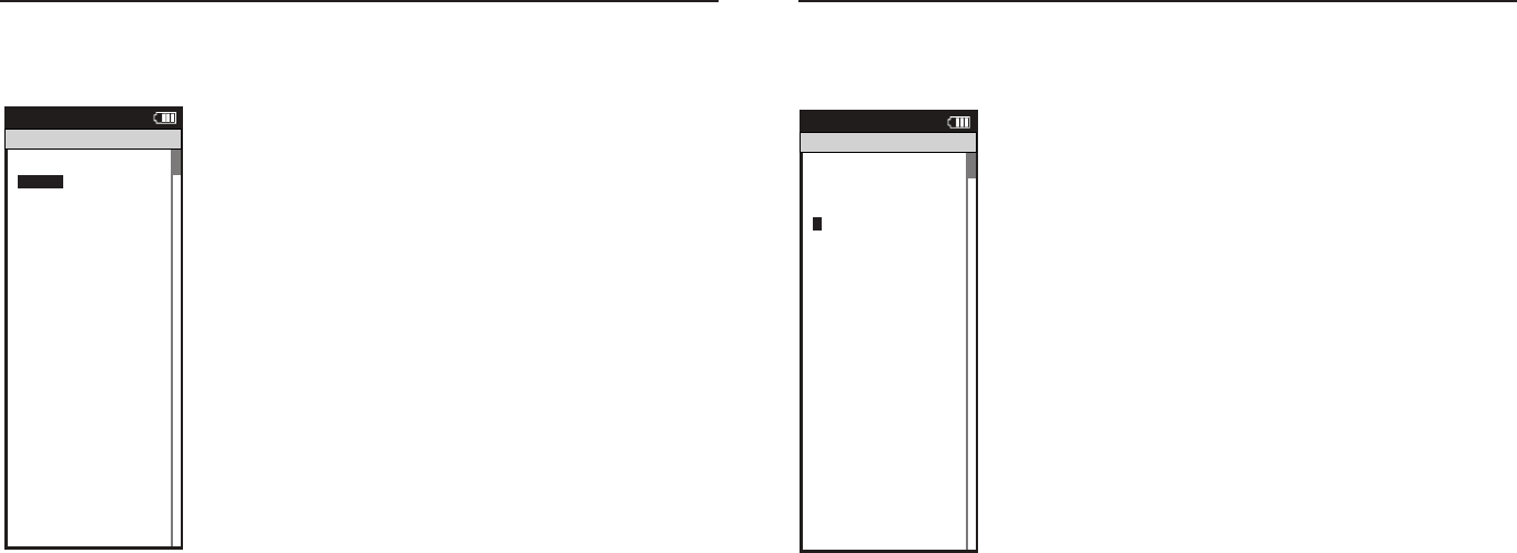
Joule 2.0 User Guide page 62
Joule 2.0 User Guide page 63
Chapter 7: Setting Up CycleOps Joule 2.0
Setting Up Joule™ Mode
1. Press and release the [MODE] button until Menu mode is displayed.
2. Press {JOYSTICK} up/down to highlight Setup Joule. Press [JOYSTICK] in and
release to select Setup Joule.
3. Press [JOYSTICK] up/down to highlight Joule Mode. Press [JOYSTICK] in and
release to select Joule Mode.
4. Press [JOYSTICK] in and release to select Record Control. Select between
speed and HRM (heart rate monitor) for record control. Speed setting starts
recording when speed is detected. Heart rate setting starts recording anytime
heart rate is detected. Press [JOYSTICK] in and release to save changes.
5. Press [JOYSTICK] up/down to highlight Sleep Time. Press [JOYSTICK] in and
release to select Sleep Time from 1, 2,3,4 and 5. Note: sleep time designates
how long Joule 2.0 stays on after not getting valid data to record, such as after
a ride. A longer sleep time will slightly effect battery life. Press [JOYSTICK] in
and release to save changes.
Workouts >
History >
PowerTest >
Preferences >
CPU Setup >
Sensors >
Main >
Exit Menu
<
Report
Menu
INT
Main
Workouts >
History >
PowerTest >
Preferences >
Setup >
Sensors >
Main >
Exit Menu
<
Report
Menu
INT
Main
Backlight Level
1 - 10
Backlight Time (sec):
Off, 2, 5, 30, 60, On
Contrast:
1 - 10
Zero averaging:
With,Without
Power Avg (sec):
1, 2, 3, 5, 10, 30
Cadence Avg (sec):
1, 2, 3, 5, 10, 30
Speed Avg (sec):
1, 2, 3, 5, 10, 30
Units:
English, Metric
CRecord Control:
Speed, HRM
Sleep Time:
1-5
Frequency
000 - 124
Power:
0-3
End Ride Time (min):
15,30,90,Never
Date:
Jan/Feb/Mar...
Time:
XX:XX am/pm
Clock Format:
12/24
OK >
Date & Time >
>
Display >
Memory >
CPU Mode >
CPU Data>
CPU Data>
XXX >
Automatic DST: >
On >
Back
<
Report
Menu
INT
CPU Setup
OK >
Date & Time >
>
Display >
Memory >
CPU Mode >
CPU Data>
CPU Data>
XXX >
Automatic DST: >
On >
Back
<
Report
Menu
INT
CPU Setup
OK >
Date & Time >
>
Display >
Memory >
CPU Mode >
CPU Data>
CPU Data>
XXX >
Automatic DST: >
On >
Back
<
Report
Menu
INT
CPU Setup
OK >
Date & Time >
>
Display >
Memory >
CPU Mode >
CPU Data>
CPU Data>
XXX >
Automatic DST: >
On >
Back
<
Report
Menu
INT
CPU Setup
Are you sure? >
Date & Time >
>
Yes>
No >
CPU Mode >
CPU Data>
CPU Data>
XXX >
Automatic DST: >
On >
Back
<
Report
Menu
INT
Clear Ride Memory
Date:>
Feb 26 2009
Time:
Clock Format:
12 >
Automatic DST: >
On >
DST Effective: >
On >
Clock Format: >
>
12
Units >
English >
The Gun Show >
Auto Zero >
>
P
HR Zones >
Pair New Sensor >
Back
<
Report
Menu
INT
Date & Time
User >
CPU >
Heart Rate Sensor >
RU Sensor >
Speed Sensor >
Back
<
Report
Menu
INT
Setup
04:55 pm
Backlight Level: >
2
Backlight Time (sec):
Contrast:
5 >
Zero averaging:>
With >
Power Avg (sec): >
1 >
Cadence Avg (sec): >
>
1
Speed Avg (sec): >
1 >
Language: >
English >
Units: >
English >
Pair New Sensor >
Back
<
Report
Menu
INT
Display
10
End Ride Time (min): >
90
Clear Memory
Clear Ride Memory >
90 >
Power Avg (sec): >
1 >
Power Zeros: >
With >
Cadence Avg (sec): >
>
1
Units: >
English >
Pair New Sensor >
Back
<
Report
Menu
INT
Memory
5
End Ride Time (min): >
90
Clear Memory
Clear ride memory >
90 >
Power Avg (sec): >
1 >
Power Zeros: >
With >
English >
English >
Back
<
Report
Menu
INT
Memory
5
OK >
Date & Time >
>
Display >
Memory >
CPU Mode >
CPU Data>
CPU Data>
XXX >
Automatic DST: >
On >
Back
<
Report
Menu
INT
CPU Setup
OK >
Date & Time >
>
Display >
Memory >
CPU Mode >
CPU Data>
Test Mode >
XXX >
Automatic DST: >
On >
Back
<
Report
Menu
INT
CPU Setup
>
Record Control >
Sleep Time:
1 >
Power Avg (sec): >
1 >
Power Zeros: >
With >
Cadence Avg (sec): >
>
1
Speed Avg (sec): >
1 >
Language: >
English >
Units: >
English >
Pair New Sensor >
Back
<
Report
Menu
INT
CPU Mode
Speed
Firmware Version: >
01:00
Odometer
Reset Odometer
90 >
Power Avg (sec): >
Designed in: >
Madison,WI by >
Saris Cycling Group >
800-783-7257 >
>
1
Speed Avg (sec): >
1 >
Language: >
English >
Units: >
English >
Pair New Sensor >
Back
<
Report
Menu
INT
CPU Data
512356
OK >
Date & Time >
>
Display >
Memory >
CPU Mode >
CPU Data>
Test Mode >
XXX >
Automatic DST: >
On >
Back
<
Report
Menu
INT
CPU Setup
Frequency >
057
Power
End Ride Time (min):
Start Radio Test >
Stop Radio Test >
Designed in: >
Madison,WI by >
Saris Cycling Group >
800-783-7257 >
Units: >
English >
Pair New Sensor >
Back
<
Report
Menu
INT
Test Mode
3
Workouts >
History >
Setup User >
Setup CPU >
Sensors
Sensors >
Main >
Exit Menu
<
Report
Menu
Main
>
Chapter 7: Setting Up CycleOps Joule 2.0
Setting Up Joule™ Data
Firmware version denotes the revision Joule 2.0 is operating on. Reference www.cycleops.com for
the latest version.
1. Press and release the [MODE] button until Menu mode is displayed.
2. Press [JOYSTICK} up/down to highlight Setup Joule. Press [JOYSTICK] in and
release to select Setup Joule.
3. Press [JOYSTICK] up/down to highlight Joule Data. Press [JOYSTICK] in and
release to select Joule Data.
4. Press [JOYSTICK] up/down to view Joule 2.0 firmware version.
5. Press [JOYSTICK] up/down to highlight Odometer. Press [JOYSTICK] in and
release to select Odometer. The odometer can be changed for a desired start
point and can be reset at any time. Press {JOYSTICK] up/down to change. Press
[JOYSTICK] in and release to save changes.
Workouts >
History >
PowerTest >
Preferences >
CPU Setup >
Sensors >
Main >
Exit Menu
<
Report
Menu
INT
Main
Workouts >
History >
PowerTest >
Preferences >
Setup >
Sensors >
Main >
Exit Menu
<
Report
Menu
INT
Main
Backlight Level
1 - 10
Backlight Time (sec):
Off, 2, 5, 30, 60, On
Contrast:
1 - 10
Zero averaging:
With,Without
Power Avg (sec):
1, 2, 3, 5, 10, 30
Cadence Avg (sec):
1, 2, 3, 5, 10, 30
Speed Avg (sec):
1, 2, 3, 5, 10, 30
Units:
English, Metric
CRecord Control:
Speed, HRM
Sleep Time:
1-5
Frequency
000 - 124
Power:
0-3
End Ride Time (min):
15,30,90,Never
Date:
Jan/Feb/Mar...
Time:
XX:XX am/pm
Clock Format:
12/24
OK >
Date & Time >
>
Display >
Memory >
CPU Mode >
CPU Data>
CPU Data>
XXX >
Automatic DST: >
On >
Back
<
Report
Menu
INT
CPU Setup
OK >
Date & Time >
>
Display >
Memory >
CPU Mode >
CPU Data>
CPU Data>
XXX >
Automatic DST: >
On >
Back
<
Report
Menu
INT
CPU Setup
OK >
Date & Time >
>
Display >
Memory >
CPU Mode >
CPU Data>
CPU Data>
XXX >
Automatic DST: >
On >
Back
<
Report
Menu
INT
CPU Setup
OK >
Date & Time >
>
Display >
Memory >
CPU Mode >
CPU Data>
CPU Data>
XXX >
Automatic DST: >
On >
Back
<
Report
Menu
INT
CPU Setup
Are you sure? >
Date & Time >
>
Yes>
No >
CPU Mode >
CPU Data>
CPU Data>
XXX >
Automatic DST: >
On >
Back
<
Report
Menu
INT
Clear Ride Memory
Date:>
Feb 26 2009
Time:
Clock Format:
12 >
Automatic DST: >
On >
DST Effective: >
On >
Clock Format: >
>
12
Units >
English >
The Gun Show >
Auto Zero >
>
P
HR Zones >
Pair New Sensor >
Back
<
Report
Menu
INT
Date & Time
User >
CPU >
Heart Rate Sensor >
RU Sensor >
Speed Sensor >
Back
<
Report
Menu
INT
Setup
04:55 pm
Backlight Level: >
2
Backlight Time (sec):
Contrast:
5 >
Zero averaging:>
With >
Power Avg (sec): >
1 >
Cadence Avg (sec): >
>
1
Speed Avg (sec): >
1 >
Language: >
English >
Units: >
English >
Pair New Sensor >
Back
<
Report
Menu
INT
Display
10
End Ride Time (min): >
90
Clear Memory
Clear Ride Memory >
90 >
Power Avg (sec): >
1 >
Power Zeros: >
With >
Cadence Avg (sec): >
>
1
Units: >
English >
Pair New Sensor >
Back
<
Report
Menu
INT
Memory
5
End Ride Time (min): >
90
Clear Memory
Clear ride memory >
90 >
Power Avg (sec): >
1 >
Power Zeros: >
With >
English >
English >
Back
<
Report
Menu
INT
Memory
5
OK >
Date & Time >
>
Display >
Memory >
CPU Mode >
CPU Data>
CPU Data>
XXX >
Automatic DST: >
On >
Back
<
Report
Menu
INT
CPU Setup
OK >
Date & Time >
>
Display >
Memory >
CPU Mode >
CPU Data>
Test Mode >
XXX >
Automatic DST: >
On >
Back
<
Report
Menu
INT
CPU Setup
>
Record Control >
Sleep Time:
1 >
Power Avg (sec): >
1 >
Power Zeros: >
With >
Cadence Avg (sec): >
>
1
Speed Avg (sec): >
1 >
Language: >
English >
Units: >
English >
Pair New Sensor >
Back
<
Report
Menu
INT
CPU Mode
Speed
Firmware Version: >
01:00
Odometer
Reset Odometer
90 >
Power Avg (sec): >
Designed in: >
Madison,WI by >
Saris Cycling Group >
800-783-7257 >
>
1
Speed Avg (sec): >
1 >
Language: >
English >
Units: >
English >
Pair New Sensor >
Back
<
Report
Menu
INT
CPU Data
512356
OK >
Date & Time >
>
Display >
Memory >
CPU Mode >
CPU Data>
Test Mode >
XXX >
Automatic DST: >
On >
Back
<
Report
Menu
INT
CPU Setup
Frequency >
057
Power
End Ride Time (min):
Start Radio Test >
Stop Radio Test >
Designed in: >
Madison,WI by >
Saris Cycling Group >
800-783-7257 >
Units: >
English >
Pair New Sensor >
Back
<
Report
Menu
INT
Test Mode
3
Workouts >
History >
Setup User >
Setup CPU >
Sensors
Sensors >
Main >
Exit Menu
<
Report
Menu
Main
>
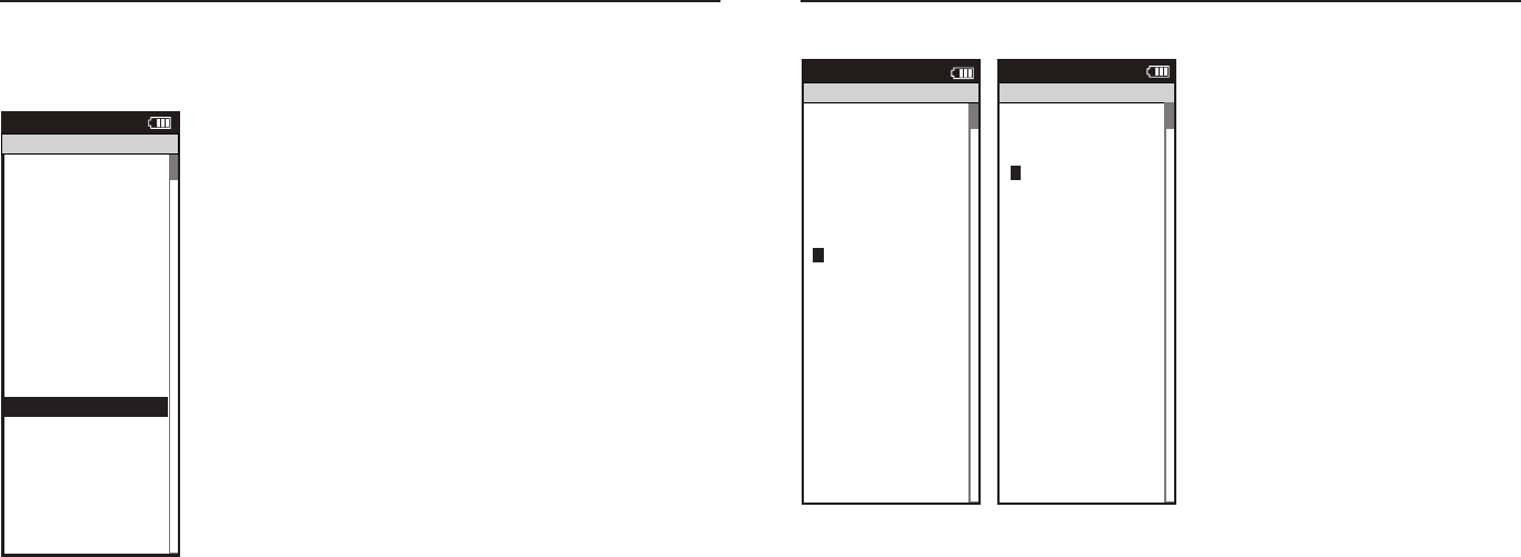
Joule 2.0 User Guide page 64
Joule 2.0 User Guide page 65
Chapter 8: Setting Up User
Setting Up User Profile
Setting up a user profile is important for Joule 2.0 to display the most accurate information. A
user profile can be set up and managed using PowerAgent software. Note: if using Joule 2.0 in
group environment, a USB stick will store user information.
1. Press and release the [MODE] button until Menu mode is displayed.
2. Press [JOYSTICK] up/down to highlight Setup User. Press [JOYSTICK] in and
release to select Setup User.
3. Press [JOYSTICK] in and release to select Name. Press [JOYSTICK] up/down to
spell desired user name. Press [JOYSTICK] in and release to save changes.
4. Press [JOYSTICK] up/down to highlight Weight. Press [JOYSTICK] in and
release to select Weight. Use [JOYSTICK] to toggle appropriate user weight.
Calculations such as: watts/kg and accurate target slope resistance require cor-
rect user weight. Press [JOYSTICK] in and release to save changes.
5. Press [JOYSTICK] up/down to highlight Height. Press [JOYSTICK] in and
release to select Height. Use [JOYSTICK] to set appropriate user height. Press
[JOYSTICK] in and release to save changes.
6. Press [JOYSTICK] up/down to highlight Date of Birth. Press [JOYSTICK] in and
release to select Date of Birth. Use [JOYSTICK] to set appropriate date of birth.
Press [JOYSTICK] in and release to save changes.
Name: >
New User
Active: >
X
Weight - lbs:
XXX >
Height - in: >
XXX >
Date of Birth: >
Feb 02 1974 >
Gender: >
>
Male
Power Zones >
HR Zones >
The Gun Show >
Auto Zero >
Power Zones >
HR Zones >
Pair New Sensor >
Back
<
Report
Menu
Setup User
>
>
XXXX XXXX >
The Gun Show >
Auto Zero >
Power Zones >
HR Zones >
Pair New Sensor >
Back
<
Report
Menu
Power Zones
Zone
Upper imit
1: Recover
12
2: ndurance
12
:Threshold
4: Race Pace >
12 >
: Ma imum >
12 >
>
: Supra Ma
MAX >
12
Name: >
esse
Active 1- : >
X
Weight - lbs:
XXX >
Height - in: >
XXX >
Date of Birth: >
Feb 02 1974 >
Gender: >
>
Male
Power Zones >
HR Zones >
The Gun Show >
Auto Zero >
Power Zones >
HR Zones >
Pair New Sensor >
Back
<
Report
Menu
Setup User
>
>
>
: Supra Ma
XXXX XXXX >
Gender >
The Gun Show >
Auto Zero >
Power Zones >
HR Zones >
Pair New Sensor >
Back
<
Report
Menu
Heart Rate Zones
Sensors >
Setup Joule >
Setup User >
Workouts >
History >
Sensors >
Main >
it Menu
<
Report
Menu
Main
Zone
Upper imit
1: Recovery
2: ndurance
12
:Threshold
4: Race Pace >
12 >
: Ma imum >
12 >
>
: Supra Ma
MAX >
12
12
Chapter 8: Setting Up User
Setting Up User Profile...continued
7. Press [JOYSTICK] up/down to highlight Gender.
Press [JOYSTICK] in and release to select Gender.
Press [JOYSTICK] up/down to change from male
to female. Press [JOYSTICK] in and release to save
changes.
8.Press [JOYSTICK] up/down to highlight Power
Zones. Press [JOYSTICK] in and release to select
Power Zones. Press [JOYSTICK] up/down to
highlight and select Recovery Zone, Endurance
Zone, Threshold Zone, Race Pace Zone and
Maximum Zone. Press [JOYSTICK] in and release
to save changes.
9.Press [JOYSTICK] up/down to highlight Heart
Rate Zones. Press [JOYSTICK] in and release to
select Heart Rate Zones. Press [JOYSTICK] up/
down to highlight and Recovery Zone, Endur-
ance Zone, Threshold Zone, Race Pace Zone and
Maximum Zone. Use [JOYSTICK] to set appropri-
ate zone values. Press [JOYSTICK] in and release to
save changes.
Name: >
New User
Active: >
X
Weight - lbs:
XXX >
Height - in: >
XXX >
Date of Birth: >
Feb 02 1974 >
Gender: >
>
Male
Power Zones >
HR Zones >
The Gun Show >
Auto Zero >
Power Zones >
HR Zones >
Pair New Sensor >
Back
<
Report
Menu
Setup User
>
>
XXXX XXXX >
The Gun Show >
Auto Zero >
Power Zones >
HR Zones >
Pair New Sensor >
Back
<
Report
Menu
Power Zones
Zone
Upper imit
1: Recover
12
2: ndurance
12
:Threshold
4: Race Pace >
12 >
: Ma imum >
12 >
>
: Supra Ma
MAX >
12
Name: >
esse
Active 1- : >
X
Weight - lbs:
XXX >
Height - in: >
XXX >
Date of Birth: >
Feb 02 1974 >
Gender: >
>
Male
Power Zones >
HR Zones >
The Gun Show >
Auto Zero >
Power Zones >
HR Zones >
Pair New Sensor >
Back
<
Report
Menu
Setup User
>
>
>
: Supra Ma
XXXX XXXX >
Gender >
The Gun Show >
Auto Zero >
Power Zones >
HR Zones >
Pair New Sensor >
Back
<
Report
Menu
Heart Rate Zones
Sensors >
Setup Joule >
Setup User >
Workouts >
History >
Sensors >
Main >
it Menu
<
Report
Menu
Main
Zone
Upper imit
1: Recovery
2: ndurance
12
:Threshold
4: Race Pace >
12 >
: Ma imum >
12 >
>
: Supra Ma
MAX >
12
12
Name: >
New User
Active: >
X
Weight - lbs:
XXX >
Height - in: >
XXX >
Date of Birth: >
Feb 02 1974 >
Gender: >
>
Male
Power Zones >
HR Zones >
The Gun Show >
Auto Zero >
Power Zones >
HR Zones >
Pair New Sensor >
Back
<
Report
Menu
Setup User
>
>
XXXX XXXX >
The Gun Show >
Auto Zero >
Power Zones >
HR Zones >
Pair New Sensor >
Back
<
Report
Menu
Power Zones
Zone
Upper imit
1: Recover
12
2: ndurance
12
:Threshold
4: Race Pace >
12 >
: Ma imum >
12 >
>
: Supra Ma
MAX >
12
Name: >
esse
Active 1- : >
X
Weight - lbs:
XXX >
Height - in: >
XXX >
Date of Birth: >
Feb 02 1974 >
Gender: >
>
Male
Power Zones >
HR Zones >
The Gun Show >
Auto Zero >
Power Zones >
HR Zones >
Pair New Sensor >
Back
<
Report
Menu
Setup User
>
>
>
: Supra Ma
XXXX XXXX >
Gender >
The Gun Show >
Auto Zero >
Power Zones >
HR Zones >
Pair New Sensor >
Back
<
Report
Menu
Heart Rate Zones
Sensors >
Setup Joule >
Setup User >
Workouts >
History >
Sensors >
Main >
it Menu
<
Report
Menu
Main
Zone
Upper imit
1: Recovery
2: ndurance
12
:Threshold
4: Race Pace >
12 >
: Ma imum >
12 >
>
: Supra Ma
MAX >
12
12

Joule 2.0 User Guide page 66
Joule 2.0 User Guide page 67
Chapter 9: History
Previous Rides
Previous rides history allows for comparisons of any selected ride to averages over 2 weeks,
4 weeks, 8 weeks, 6 moths or 12 months prior to the selected ride. Note: the averages do not
include the selected ride.
1. Press and release the [MODE] button until Menu
mode is displayed.
2. Press [JOYSTICK] up/down to highlight History.
3. Press [JOYSTICK] in and release to select History.
4. Press [JOYSTICK] in and release to select Previous
Rides.
5. Press [JOYSTICK] up/down to highlight desired
ride. Note: each ride is named using the format
YYYYMMDD HHMMSS so a ride listed as 20091120
154335 was created November 20th, 2009 at 3:43:35
PM.
6. Press [JOYSTICK] in and release to select the
desired ride. Note: Reports are now shown with 3
columns; the fi rst column is the metric label, the
second column is the data for a given metric on the
selected ride and the 3rd column is the average of all
rides completed over the selected date range.
7. Press [JOYSTICK] in and release to change the
selected data range from 2 weeks, 4 weeks, 8 weeks,
6 months and 12 months.
8. Press [JOYSTICK] left/right to change reports and
exit History reports.
Note: Rides will be organized and sorted by date,
with most current date at top.
Previous Rides >
Reports - Max >
Reports - Totals >
Back
<
Report
Menu
History
Select by Date>
20090731123542 >
20090731123542 >
Back
<
Report
Menu
History - Previous Rides
Select by Date>
Back
<
Report
Menu
History - Previous Rides
Previous Rides >
Reports - Max >
Reports - Totals >
Reports - Max >
Back
<
Report
Menu
History
Report
History
2/2/09
RIDE
TIME
AV
WATTS
AV
CAD
2wk mean
Summary
MILES
9999 9999
KJ
9999 9999
9999 9999
250 250
AV
MPH
99 99
AV
HR
240 240
99:59:59 99:59:59
Report
History
2/2/09
5 SEC
5 MIN
20 MIN
2wk mean
Peak Power
30 SEC
2999 2999
1 MIN
2999 2999
2999 2999
2999 2999
30 MIN
2999 2999
40 MIN
2999 2999
60 MIN
2999 2999
2999 2999
Report
History
2/2/09
1
4
5
2wk mean
Time in Power Zones
2
99:59:59 99:59:59
3
99:59:59 99:59:59
99:59:59 99:59:59
99:59:59 99:59:59
6
99:59:59 99:59:59
1
100% 100%
2
100% 100%
3
100% 100%
4
100% 100%
5
100% 100%
6
100% 100%
99:59:59 99:59:59
Report
History
2/2/09
1
4
5
2wk mean
Time in HR Zones
2
99:59:59 99:59:59
3
99:59:59 99:59:59
99:59:59 99:59:59
99:59:59 99:59:59
1
100% 100%
2
100% 100%
3
100% 100%
4
100% 100%
5
100% 100%
99:59:59 99:59:59
Report
History
2/2/09
FT
GAIN
VA M
2wk mean
Climbing
AV
GRADE
100% 100%
FT
LOST
9999 9999
9999 9999
9999 9999
Report
History
2/2/09
AV
WATTS
ZERO
WATTS
NP
2wk mean
Power Detail
MX
WATTS
9999 9999
ZERO
WATTS
100% 100%
2999 2999
AV
W/KG
2999 2999
MX
W/KG
2999 2999
9999 9999
99:59:59 99:59:59
Report
History
MAX
RIDE
TIME
AV
WATTS
AV
CAD
2WK MEAN
Summary
MILES
9999 9999
KJ
9999 9999
9999 9999
250 250
AV
MPH
99 99
AV
HR
240 240
99:59:59 99:59:59
Report
History
MAX
5 SEC
5 MIN
20 MIN
2WK MEAN
Peak Power
30 SEC
2999 2999
1 MIN
2999 2999
2999 2999
2999 2999
30 MIN
2999 2999
40 MIN
2999 2999
60 MIN
2999 2999
2999 2999
Report
History
MAX
1
4
5
2WK MEAN
Time in Power Zones
2
99:59:59 99:59:59
3
99:59:59 99:59:59
99:59:59 99:59:59
99:59:59 99:59:59
6
99:59:59 99:59:59
1
100% 100%
2
100% 100%
3
100% 100%
4
100% 100%
5
100% 100%
6
100% 100%
99:59:59 99:59:59
Report
History
MAX
1
4
5
2WK MEAN
Time in HR Zones
2
99:59:59 99:59:59
3
99:59:59 99:59:59
99:59:59 99:59:59
99:59:59 99:59:59
1
100% 100%
2
100% 100%
3
100% 100%
4
100% 100%
5
100% 100%
99:59:59 99:59:59
Report
History
MAX
FT
GAIN
VA M
2WK MEAN
Climbing
AV
GRADE
100% 100%
FT
LOST
9999 9999
9999 9999
9999 9999
Report
History
MAX
AV
WATTS
ZERO
WATTS
NP
2WK MEAN
Power Detail
MX
WATTS
9999 9999
ZERO
WATTS
100% 100%
2999 2999
AV
W/KG
2999 2999
MX
W/KG
2999 2999
9999 9999
99:59:59 99:59:59
Previous Rides >
Reports - Max >
Reports - Totals >
Reports - Max >
Back
<
Report
Menu
History
Report
History
TOT A L
RIDE
TIME
CAL
FT
GAIN
2WK MEAN
Summary
MILES
9999 9999
KJ
9999 9999
9999 9999
9999 9999
AV
MPH
99 99
AV
HR
240 240
99:59:59 99:59:59
Report
History
TOT A L
1
4
5
2WK MEAN
Time in Power Zones
2
99:59:59 99:59:59
3
99:59:59 99:59:59
99:59:59 99:59:59
99:59:59 99:59:59
6
99:59:59 99:59:59
1
100% 100%
2
100% 100%
3
100% 100%
4
100% 100%
5
100% 100%
6
100% 100%
99:59:59 99:59:59
Report
History
TOT A L
1
4
5
2WK MEAN
Time in HR Zones
2
99:59:59 99:59:59
3
99:59:59 99:59:59
99:59:59 99:59:59
99:59:59 99:59:59
1
100% 100%
2
100% 100%
3
100% 100%
4
100% 100%
5
100% 100%
99:59:59 99:59:59
Report
History
2/2/09
KJ
2WK MEAN
Work
KJ/HR
9999 9999
TSS
500 500
IF
250 250
9999 9999
Report
History
MAX
KJ
2WK MEAN
Work
KJ/HR
9999 9999
TSS
500 500
IF
250 250
9999 9999
Workouts >
History >
Setup User >
Setup CPU >
Sensors >
Sensors >
Main >
Exit Menu
<
Report
Menu
Main
Sensors
Setup Joule
Setup ser
Workouts
History
Sensors
in
it enu
eport
Menu
in
Chapter 9: History
Maximum History
Maximum History reports allows for comparisons of the maximum values achieved in a selected
time frame to the averages achieved in that same time frame.
1. Press and release the [MODE] button until Menu
mode is displayed.
2. Press [JOYSTICK] up/down to highlight History.
3. Press [JOYSTICK] in and release to select History.
4. Press [JOYSTICK] in and release to select Reports
– Max. Note: Reports are now shown with 3 columns;
the fi rst column is the metric label, the second
column is the maximum value achieved for a given
metric over the selected time frame and the 3rd
column is the average of all rides completed over the
selected date range.
5. Press [JOYSTICK] in and release to change the
selected data range from 2 weeks, 4 weeks, 8 weeks,
6 months and 12 months.
6. Press [JOYSTICK] left/right to change reports and
exit History reports.
Note: Max view is the max values achieved for each
report metric over the average on two week, four
week, etc.
Sensors
Setup Joule
Setup ser
Workouts
History
Sensors
in
it enu
eport
Menu
in
Previous Rides >
Reports - Max >
Reports - Totals >
Back
<
Report
Menu
History
Select by Date>
20090731123542 >
20090731123542 >
Back
<
Report
Menu
History - Previous Rides
Select by Date>
Back
<
Report
Menu
History - Previous Rides
Previous Rides >
Reports - Max >
Reports - Totals >
Reports - Max >
Back
<
Report
Menu
History
Report
History
2/2/09
RIDE
TIME
AV
WATTS
AV
CAD
2wk mean
Summary
MILES
9999 9999
KJ
9999 9999
9999 9999
250 250
AV
MPH
99 99
AV
HR
240 240
99:59:59 99:59:59
Report
History
2/2/09
5 SEC
5 MIN
20 MIN
2wk mean
Peak Power
30 SEC
2999 2999
1 MIN
2999 2999
2999 2999
2999 2999
30 MIN
2999 2999
40 MIN
2999 2999
60 MIN
2999 2999
2999 2999
Report
History
2/2/09
1
4
5
2wk mean
Time in Power Zones
2
99:59:59 99:59:59
3
99:59:59 99:59:59
99:59:59 99:59:59
99:59:59 99:59:59
6
99:59:59 99:59:59
1
100% 100%
2
100% 100%
3
100% 100%
4
100% 100%
5
100% 100%
6
100% 100%
99:59:59 99:59:59
Report
History
2/2/09
1
4
5
2wk mean
Time in HR Zones
2
99:59:59 99:59:59
3
99:59:59 99:59:59
99:59:59 99:59:59
99:59:59 99:59:59
1
100% 100%
2
100% 100%
3
100% 100%
4
100% 100%
5
100% 100%
99:59:59 99:59:59
Report
History
2/2/09
FT
GAIN
VA M
2wk mean
Climbing
AV
GRADE
100% 100%
FT
LOST
9999 9999
9999 9999
9999 9999
Report
History
2/2/09
AV
WATTS
ZERO
WATTS
NP
2wk mean
Power Detail
MX
WATTS
9999 9999
ZERO
WATTS
100% 100%
2999 2999
AV
W/KG
2999 2999
MX
W/KG
2999 2999
9999 9999
99:59:59 99:59:59
Report
History
MAX
RIDE
TIME
AV
WATTS
AV
CAD
2WK MEAN
Summary
MILES
9999 9999
KJ
9999 9999
9999 9999
250 250
AV
MPH
99 99
AV
HR
240 240
99:59:59 99:59:59
Report
History
MAX
5 SEC
5 MIN
20 MIN
2WK MEAN
Peak Power
30 SEC
2999 2999
1 MIN
2999 2999
2999 2999
2999 2999
30 MIN
2999 2999
40 MIN
2999 2999
60 MIN
2999 2999
2999 2999
Report
History
MAX
1
4
5
2WK MEAN
Time in Power Zones
2
99:59:59 99:59:59
3
99:59:59 99:59:59
99:59:59 99:59:59
99:59:59 99:59:59
6
99:59:59 99:59:59
1
100% 100%
2
100% 100%
3
100% 100%
4
100% 100%
5
100% 100%
6
100% 100%
99:59:59 99:59:59
Report
History
MAX
1
4
5
2WK MEAN
Time in HR Zones
2
99:59:59 99:59:59
3
99:59:59 99:59:59
99:59:59 99:59:59
99:59:59 99:59:59
1
100% 100%
2
100% 100%
3
100% 100%
4
100% 100%
5
100% 100%
99:59:59 99:59:59
Report
History
MAX
FT
GAIN
VA M
2WK MEAN
Climbing
AV
GRADE
100% 100%
FT
LOST
9999 9999
9999 9999
9999 9999
Report
History
MAX
AV
WATTS
ZERO
WATTS
NP
2WK MEAN
Power Detail
MX
WATTS
9999 9999
ZERO
WATTS
100% 100%
2999 2999
AV
W/KG
2999 2999
MX
W/KG
2999 2999
9999 9999
99:59:59 99:59:59
Previous Rides >
Reports - Max >
Reports - Totals >
Reports - Max >
Back
<
Report
Menu
History
Report
History
TOT A L
RIDE
TIME
CAL
FT
GAIN
2WK MEAN
Summary
MILES
9999 9999
KJ
9999 9999
9999 9999
9999 9999
AV
MPH
99 99
AV
HR
240 240
99:59:59 99:59:59
Report
History
TOT A L
1
4
5
2WK MEAN
Time in Power Zones
2
99:59:59 99:59:59
3
99:59:59 99:59:59
99:59:59 99:59:59
99:59:59 99:59:59
6
99:59:59 99:59:59
1
100% 100%
2
100% 100%
3
100% 100%
4
100% 100%
5
100% 100%
6
100% 100%
99:59:59 99:59:59
Report
History
TOT A L
1
4
5
2WK MEAN
Time in HR Zones
2
99:59:59 99:59:59
3
99:59:59 99:59:59
99:59:59 99:59:59
99:59:59 99:59:59
1
100% 100%
2
100% 100%
3
100% 100%
4
100% 100%
5
100% 100%
99:59:59 99:59:59
Report
History
2/2/09
KJ
2WK MEAN
Work
KJ/HR
9999 9999
TSS
500 500
IF
250 250
9999 9999
Report
History
MAX
KJ
2WK MEAN
Work
KJ/HR
9999 9999
TSS
500 500
IF
250 250
9999 9999
Workouts >
History >
Setup User >
Setup CPU >
Sensors >
Sensors >
Main >
Exit Menu
<
Report
Menu
Main

Joule 2.0 User Guide page 68
Joule 2.0 User Guide page 69
Chapter 9: History
Total History
Totals History reports allows for comparisons of the totals achieved in a selected time frame to
the averages achieved in that same time frame.
1. Press and release the [MODE] button until Menu
mode is displayed.
2. Press [JOYSTICK] up/down to highlight History.
3. Press [JOYSTICK] in and release to select History.
4. Press [JOYSTICK] in and release to select Reports
– Totals. Note: Reports are now shown with 3 col-
umns; the first column is the metric label, the second
column is the total value achieved for a given metric
over the selected time frame and the 3rd column is
the average of all rides completed over the selected
date range.
5. Press [JOYSTICK] in and release to change the
selected data range from 2 weeks, 4 weeks, 8 weeks,
6 months and 12 months.
6. Press [JOYSTICK] left/right to change reports and
exit History reports.
Note: Total view is the total values achieved for each
report metric over the average on two week, four
week, etc.
Sensors
Setup Joule
Setup ser
Workouts
History
Sensors
in
it enu
eport
Menu
in
Previous Rides >
Reports - Max >
Reports - Totals >
Back
<
Report
Menu
History
Select by Date>
20090731123542 >
20090731123542 >
Back
<
Report
Menu
History - Previous Rides
Select by Date>
Back
<
Report
Menu
History - Previous Rides
Previous Rides >
Reports - Max >
Reports - Totals >
Reports - Max >
Back
<
Report
Menu
History
Report
History
2/2/09
RIDE
TIME
AV
WATTS
AV
CAD
2wk mean
Summary
MILES
9999 9999
KJ
9999 9999
9999 9999
250 250
AV
MPH
99 99
AV
HR
240 240
99:59:59 99:59:59
Report
History
2/2/09
5 SEC
5 MIN
20 MIN
2wk mean
Peak Power
30 SEC
2999 2999
1 MIN
2999 2999
2999 2999
2999 2999
30 MIN
2999 2999
40 MIN
2999 2999
60 MIN
2999 2999
2999 2999
Report
History
2/2/09
1
4
5
2wk mean
Time in Power Zones
2
99:59:59 99:59:59
3
99:59:59 99:59:59
99:59:59 99:59:59
99:59:59 99:59:59
6
99:59:59 99:59:59
1
100% 100%
2
100% 100%
3
100% 100%
4
100% 100%
5
100% 100%
6
100% 100%
99:59:59 99:59:59
Report
History
2/2/09
1
4
5
2wk mean
Time in HR Zones
2
99:59:59 99:59:59
3
99:59:59 99:59:59
99:59:59 99:59:59
99:59:59 99:59:59
1
100% 100%
2
100% 100%
3
100% 100%
4
100% 100%
5
100% 100%
99:59:59 99:59:59
Report
History
2/2/09
FT
GAIN
VA M
2wk mean
Climbing
AV
GRADE
100% 100%
FT
LOST
9999 9999
9999 9999
9999 9999
Report
History
2/2/09
AV
WATTS
ZERO
WATTS
NP
2wk mean
Power Detail
MX
WATTS
9999 9999
ZERO
WATTS
100% 100%
2999 2999
AV
W/KG
2999 2999
MX
W/KG
2999 2999
9999 9999
99:59:59 99:59:59
Report
History
MAX
RIDE
TIME
AV
WATTS
AV
CAD
2WK MEAN
Summary
MILES
9999 9999
KJ
9999 9999
9999 9999
250 250
AV
MPH
99 99
AV
HR
240 240
99:59:59 99:59:59
Report
History
MAX
5 SEC
5 MIN
20 MIN
2WK MEAN
Peak Power
30 SEC
2999 2999
1 MIN
2999 2999
2999 2999
2999 2999
30 MIN
2999 2999
40 MIN
2999 2999
60 MIN
2999 2999
2999 2999
Report
History
MAX
1
4
5
2WK MEAN
Time in Power Zones
2
99:59:59 99:59:59
3
99:59:59 99:59:59
99:59:59 99:59:59
99:59:59 99:59:59
6
99:59:59 99:59:59
1
100% 100%
2
100% 100%
3
100% 100%
4
100% 100%
5
100% 100%
6
100% 100%
99:59:59 99:59:59
Report
History
MAX
1
4
5
2WK MEAN
Time in HR Zones
2
99:59:59 99:59:59
3
99:59:59 99:59:59
99:59:59 99:59:59
99:59:59 99:59:59
1
100% 100%
2
100% 100%
3
100% 100%
4
100% 100%
5
100% 100%
99:59:59 99:59:59
Report
History
MAX
FT
GAIN
VA M
2WK MEAN
Climbing
AV
GRADE
100% 100%
FT
LOST
9999 9999
9999 9999
9999 9999
Report
History
MAX
AV
WATTS
ZERO
WATTS
NP
2WK MEAN
Power Detail
MX
WATTS
9999 9999
ZERO
WATTS
100% 100%
2999 2999
AV
W/KG
2999 2999
MX
W/KG
2999 2999
9999 9999
99:59:59 99:59:59
Previous Rides >
Reports - Max >
Reports - Totals >
Reports - Max >
Back
<
Report
Menu
History
Report
History
TOT A L
RIDE
TIME
CAL
FT
GAIN
2WK MEAN
Summary
MILES
9999 9999
KJ
9999 9999
9999 9999
9999 9999
AV
MPH
99 99
AV
HR
240 240
99:59:59 99:59:59
Report
History
TOT A L
1
4
5
2WK MEAN
Time in Power Zones
2
99:59:59 99:59:59
3
99:59:59 99:59:59
99:59:59 99:59:59
99:59:59 99:59:59
6
99:59:59 99:59:59
1
100% 100%
2
100% 100%
3
100% 100%
4
100% 100%
5
100% 100%
6
100% 100%
99:59:59 99:59:59
Report
History
TOT A L
1
4
5
2WK MEAN
Time in HR Zones
2
99:59:59 99:59:59
3
99:59:59 99:59:59
99:59:59 99:59:59
99:59:59 99:59:59
1
100% 100%
2
100% 100%
3
100% 100%
4
100% 100%
5
100% 100%
99:59:59 99:59:59
Report
History
2/2/09
KJ
2WK MEAN
Work
KJ/HR
9999 9999
TSS
500 500
IF
250 250
9999 9999
Report
History
MAX
KJ
2WK MEAN
Work
KJ/HR
9999 9999
TSS
500 500
IF
250 250
9999 9999
Workouts >
History >
Setup User >
Setup CPU >
Sensors >
Sensors >
Main >
Exit Menu
<
Report
Menu
Main
For most up to date Frequently Asked Questions, visit www.cycleops.com.
No display on computer screen
· Computer is asleep – Press [MODE] or [INTERVAL] on the computer to wake up the computer.
· Computer is too cold- operating temp. is 32 to 110 degrees Fahrenheit
Computer display is fully discharged
· It will need to be recharged for at least 30 minutes.
Computer display is on, but there is no transmission of data.
· Hub is asleep - spin the wheel to wake up the hub.
· Computer has not “found” the hub. Press and hold [MODE] and [INTERVAL] until “Find” appears
on Title Bar. Make sure hub is awake by rotating wheel once.
· Batteries need replacement - replace the hub batteries as shown in the maintenance section
of the User Guide
Power seems incorrect
·Torque value is not zeroed. To manually zero torque, go to Menu, Sensors, Select Sensor, Calibra-
tion. Manual Zero the hub. Torque is now being displayed.
If re-zeroing the torque does not recalibrate the unit, call Saris Cycling Group customer service
at 1-800-783-7257.
Speed seems incorrect
· Wheel size incorrect -refer to Sensors to enter the correct size in corresponding sensor.
Chapter 10: Troubleshooting CycleOps Joule 2.0

Joule 2.0 User Guide page 70
Joule 2.0 User Guide page 71
WARNING: Always consult a physician before beginning or modifying any exercise program.
Precautions:
Keep eyes on the road. Do not become overly engaged with CycleOps Joule 2.0 display. •
We recommend getting familiar with the computer functions while stationary.•
The computer and chest strap are water resistant, not water proof. Avoid sustained •
water contact and do not deliberately place CycleOps Joule 2.0 or its components in
water or under high-pressure sprays.
Avoid spraying the unit directly with solvent mixture. Do not use thinner or other •
solvents to clean parts.
Failure to adhere to these precautions may cause premature failure or incorrect opera-•
tion of the unit and may void the warranty.
Disconnecting:
To avoid losing data, never disconnect the USB port while data is being written. To properly dis-
connect Joule 2.0 close all appropriate windows. If a drive window is open, close any associated
windows before attempting to disconnect your Joule™.
Windows® Operating System •
Use the “Safely Remove Hardware” icon in the notification area of the taskbar to safely remove
the device before unplugging. The notification area is to the right of the taskbar where you usu-
ally see the current time displayed.
1. In the notification area, left-click on the “Safely Remove Hardware” icon .
2. Select the device you want to unplug.
3. When Windows notifies you that it is safe to do so, unplug the Joule™ from
your computer.
Mac OS® Operating system Software •
1. In a Finder window, click the eject icon next to your Joule™ as shown below.
2. Unplug your Joule™.
Chapter 11: Important Precautions
Battery Warnings:
Charge battery at temperature range of 0-45 degrees Celsius. engaged with CycleOps •
Joule 2.0 display.
Do not immerse the battery in water or seawater, and keep the battery in a cool dry •
environment during stands by period.
Do not connect the battery to an electrical outlet.•
Do not strike or throw the battery against hard surfaces. •
Do not transportor store the battery together with metal objects such as necklaces, •
hairpins, etc.
Do not heat or dispose in fire or water. Do not modify or disassembly the battery. It will •
be dangerous and may cause ignition, heating leakage or explosion.
Do not short-circuit positive (+) and negative (-) terminals. Keep away from metal or •
other conductive materials. Jumbling the batteries of direct contact with positive (+)
and negative (-) terminals or other conductive materials may cause short-circuit.
Do not reverse the positive (+) and negative (-) terminals. •
Do not solder the battery directly. Excessive heating may cause deformation of the bat-•
tery components such as the gasket, which may lead to the battery swelling, leakage,
explosion or ignition.
Do not use abnormal cell which has damages by shipping stress, drop short or some-•
thing else, and which gives off electrolyte odor.
Do not use battery in a location where static electricity is rich, otherwise, the safety •
devices may be damaged, causing a harmful situation.
If the battery gives off an odor, generates heat or becomes discolored, or in any way •
appears abnormal during use, recharging or storage, immediately remove it from the
device or battery charger and stop using it.
Do not use sharp things to hit the battery. •
O-rings should be inspected and replaced if necessary whenever the battery cover •
is removed. Use a light coating of grease when re-installing the battery cover on the
O-rings.
Chapter 11: Important Precautions

Joule 2.0 User Guide page 72
Joule 2.0 User Guide page 73
FCC Statement of Compliance:
Statement of Compliance for FCC and Industry Canada:
“This device complies with Industry Canada and Part 15 of the FCC Rules. Operation is subject
to the following two conditions: (1) This device may not cause harmful interference, and (2) this
device must accept any interference received, including interference that may cause undesired
operation.”
The term “IC:” before the radio certification number only signifies that Industry Canada technical
specifications were met.
Changes or modifications to this device not expressly approved by the party responsible for
compliance with FCC regulations (the manufacturer) could void the user’s authority to operate
the equipment.
NOTE: This equipment has been tested and found to comply with the limits for a Class B digital
device, pursuant to Part 15 of the FCC Rules. These limits are designed to provide reasonable
protection against harmful interference in a residential installation. This equipment generates,
uses and can radiate radio frequency energy and, if not installed and used in accordance with
the instructions, may cause harmful interference to radio communications. However, there is no
guarantee that interference will not occur in a particular installation. If this equipment does cause
harmful interference to radio or television reception, which can be determined by turning the
equipment off and on, the user is encouraged to try to correct the interference by one or more of
the following measures:
-- Reorient or relocate the receiving antenna.
-- Increase the separation between the equipment and receiver.
-- Connect the equipment into an outlet on a circuit different from that to which the receiver is
connected.
-- Consult the dealer or an experienced radio/TV technician for help.
Chapter 11: Important Precautions Chapter 12: Technical Specifications for CycleOps Joule 2.0
FEATURES: JOULE 2.0
Unit dimensions, WxHxD: 2 inches (49.5mm )wide,
3.5 inches (89.5mm) high,
1 inch (25.5mm) deep
Display size, WxH: 2.2 inches (55.88mm)
diagonal
Display resolution, WxH: 128 x 160 pixels
Weight: 2.6 ounces (74 grams)
Battery: rechargeable li-polymer
Battery life: 20 hours, typical
Handlebar or stem mount Yes
Wrist mount No
Indoor Cycle Mount
included
No
Interval specific button Yes
Resistance specific control No
Barometric Altimeter Yes
Water resistant: Yes
Mass storage device Yes
Onboard Memory 4 MB
Accepts data cards: microSD™ card (not
included)
Intervals 999
1 second ride data Approx. 20 hours (1 hr.
= 150 KB)
Ride History Approx. 500 rides (1 ride
= 1 KB)
Workouts Approx. 100 workouts (1
workout = ~5 KB)
Metrics available for history 58
Historical averages for 2 wk,
4 wk, 8 wk, 6 mo., 12 mo.
Yes
Surge count Yes
Watts/kg Yes
TSS Yes
Water resistant Yes
Water proof No
FEATURES: JOULE 2.0
IF Yes
Normalized Power Yes
Temperature Yes
Altitude (barometric
pressure)
Yes
Altitude gained Yes
Altitude lost Yes
% grade Yes
VAM Yes
KJ and KJ per hour Yes
Peak Power Yes
Power Zones Yes
Heart Rate Zones Yes
ANT+ Power Sensor
compatible
Yes
ANT+ Heart Rate Sensor
compatible
Yes
ANT+ Speed Sensor
compatible
Yes
ANT+ Cadence Sensor
compatible
Yes
ANT+ Speed/Cadence
Sensor compatible
No
Automatic sync (automati-
cally transfers data to your
computer)
No
Virtual pacer No
Auto Pause (pauses and
resumes timer based on
speed or HR)
Yes
Auto Lap (automatically
starts a new lap)
Yes
Auto Scroll (cycles through
data pages during workout)
No
Advanced workouts (create
custom, goal-oriented
workouts)
Yes
Audible alarms No
Customizable screen(s) Yes (Dashboard Mode)

Joule 2.0 User Guide page 74
Joule 2.0 User Guide page 75
Chapter 13: CycleOps Joule™ 2.0 Warranty
CycleOps Joule 2.0 is warranted to the original retail purchaser to be free from defects in materi-
als and workmanship. Warranty coverage is valid to the original purchaser only and proof of
purchase will be required.
Electronics - 1 year
This warranty does not cover:
1. Normal wear and tear.
2. Any damage, failure or loss caused by accident, misuse, neglect, abuse, improper assembly,
improper maintenance, or failure to follow instructions or warnings in User Guide .
3. Use of products in a manner or environment for which they were not designed.
Limitations
The foregoing warranties are in lieu of and exclude all other warranties not expressly set forth
herein, whether expressed or implied by operation of law or otherwise, including, but not limited
to, warranties of merchantability or fitness for a particular purpose. Saris Cycling Group shall in no
event be liable for incidental or consequential losses, damages or expenses in connection with its
exercise products. Saris Cycling Group’s liability hereunder is expressly limited to the replacement
of goods not complying with this warranty or, at Saris Cycling Group election, to the repayment of
an amount of the purchase price of the exercise product in question. Some states do not permit
the exclusion or limitation of implied warranties or incidental or consequential damages, so the
preceding limitations and exclusions may not apply to.
Procedures
Warranty service will be performed by Saris Cycling Group or an authorized Saris Cycling Group
Dealer. The original purchaser must provide proof of purchase. Service calls and/or transaction to
and from the Authorized Saris Cycling Group Dealer are the responsibility of the purchaser.
Absolute Intensity
1. The actual intensity value. For example, 300 watts, 175 beats per minute, or a 7 on a 1 to 10 RPE
chart.
Angular Velocity
1. The rate at which a spinning object rotates. 2. How fast something is spinning in units of angle
per unit time such as degrees per second. 3. Angular displacement divided by elapsed time dur-
ing which the displacement occurs. 4. Cadence or the number of revolutions a rotating object
such as a pedal makes in a given time frame. 5. At the pedals or rear hub, power is equal to torque
multiplied by angular velocity, thus angular velocity is equal to power divided by torque.
Calorie
1. A unit of energy equal to that needed to raise the temperature of 1 gram or ml of water 1 ˚C. 2.
A measure of thermal energy or the energy released when a fuel or substrate is burned.
Category 1 to 4 Climb
1. A rating system used to rank the difficulty of a climb that is based on a combination of the
length, grade, and location of the climb on the course. A category 1 climb is considered the most
difficult while a category 4 climb is considered the least difficult.
Elevation
1. The total vertical distance in feet or meters above sea level where 1 meter is equal to 3.224 feet.
Endurance Zone
1. A moderate exercise intensity where there is some stress or strain on the body 2. On a 1 to 10
RPE scale, an intensity corresponding to 3 to 4 or “moderate” to “sort of hard”. 3. On a 6 to 20 RPE
scale, an intensity corresponding to a 10 to 13 or “fairly light” to “somewhat hard.” 4. An exercise
intensity depending on the aerobic metabolism of both fat and carbohydrate. 5. An exercise
intensity that can be held as long as the athlete were supplied with an influx of carbohydrate (i.e.,
allowed to eat).
Chapter 14: Definition of Common Training Terms

Joule 2.0 User Guide page 76
Joule 2.0 User Guide page 77
Chapter 14: Definition of Common Training Terms
Force
1. A vector quantity that produces an acceleration of a body in the direction of its application. 2.
To push. 3. The amount of pressure applied to the pedals or rear hub. 4. A measure of strength. 5.
Power divided by velocity.
Gross Mechanical Efficiency (GME)
1. The percentage of stored energy or food burned by the body that is converted to actual power
output. For an average person riding a bicycle the gross mechanical efficiency is equal to 22%.
Thus, for every 100 Kcals burned by an average person, only 22 Kcals is converted to actual power
at the pedals or rear hub. The rest is simply dissipated as heat or is used for other non-pedaling
functions. 2. In the past GME has been shown to be an important predictor of cycling perfor-
mance. Recent evidence, however, is controversial. Still, there are reports that the highest GME’s
found are in riders competing in grand tours like the Tour de France.
Hors Category Climb
1. A climb that is so difficult that it is beyond categorization. 2. Any climb longer and steeper than
a category 1 climb. 3. The most difficult climb in the Tour de France.
Horsepower
1. A measure of power where 1 horsepower is equal to 746 watts.
Intensity
1. The actual or perceived difficulty of a given workout, ride, or exercise bout. 2. The power output
or rate of energy expenditure. 3. How hard a workout, ride or exercise bout is. 4. The heat or tem-
perature. 5. The degree of difficulty. 6. Stress, when measured directly as the actual power output.
7. Strain, when measured as the response to a given power output (e.g., heart rate, perceived
exertion, oxygen consumption) 8. The percent of some reference maximal or sub-maximal value.
Chapter 14: Definition of Common Training Terms
Kilocalorie or Kcal
1. 1000 calories. 2. A unit of energy equal to that needed to raise the temperature of 1 kilogram or
liter of water 1 ˚C. 3. A measure of the amount of energy in food 4. On U.S. food labels, 1 Calo-
rie, spelled with a capital “C”, rather than a lower case “c” is equal to 1 Kilocalorie or Kcal. 5. 4.186
Kjoules 6. For a given person, the total energy burned in Kcals is equal to the total Kjoules of work
performed on a bicycle divided by 4.186 divided by the percent fraction (i.e., 22% = 0.22) of that
person’s gross mechanical efficiency. 7. 1 to 1.2 multiplied by the total Kjoules.
Lactate Threshold (LT) Zone
1. A hard intensity zone marked by a sudden increase in breathing rate. 2. On a 1 to 10 RPE scale, an
intensity corresponding to a 5 to 7 or “hard” to “really hard.” 3. On a 6 to 20 RPE scale, an intensity
corresponding to a 13 to 16 or “somewhat hard” to “very hard”. 4. A range of exercise intensity
beginning at a slight inflection or rise in the blood lactate over a resting baseline to an intensity
corresponding with a blood lactate 2 to 3 mM above a resting baseline. 5. A demarcation between
aerobic metabolism to a mix of anaerobic and aerobic metabolism. 6. An all out exercise intensity
that can be held between 40 minutes to 2 hours depending on the availability of stored carbohy-
drate or glycogen within the body.
Lactate Threshold
1. An exercise intensity where the production of lactate or appearance of lactate in the blood
exceeds the removal or disappearance of lactate from the blood. 2. An exercise intensity character-
ized by a sudden increase in breathing rate or ventilation. 3. An exercise intensity where individu-
als begin to feel a burning sensation in working muscle. 4. An exercise intensity considered to be
hard. 5. An exercise intensity that can be held for a prolonged period of time ranging from 40 min-
utes to 2 hours. 6. Amongst athletes with similar VO2 max values the power at lactate threshold is
the strongest predictor of performance.
Lactate Threshold Break Point
1. The power output or exercise intensity where blood lactate just begins to increase above its
resting baseline. 2. An exercise intensity characterized as somewhat hard. 3. The upper end of the
endurance training zone and the bottom end of the lactate threshold zone. 4. An exercise intensity
that can be held for 1 to 3 hours or as long as there is available stored carbohydrate or glycogen.
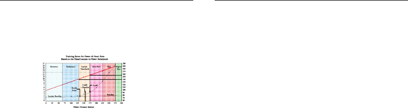
Joule 2.0 User Guide page 78
Joule 2.0 User Guide page 79
Chapter 14: Defi nition of Common Training Terms
Lactate Threshold > 1mM
1. The power output or exercise intensity where the blood lactate is equal to 1 mM above its
resting baseline. 2. An exercise intensity characterized as hard. 3. The mid point of the lactate
threshold training zone. 4. An exercise intensity that can be held for 1 to 2 hours.
Lactate Threshold 4 mM
1. The power output or exercise intensity at a blood lactate level of 4 mM or 2 to 3 mM above
baseline. 2. An exercise intensity characterized as very hard. 3. The upper limit of the lactate
threshold zone. 4. An exercise intensity that can be held for 30 minutes to 1 hour.
Normalized Intensity
1. The intensity normalized to some other factor such as body weight or aerodynamic drag. For
example, for a 70 kg person, 300 watts would be represented as 4.3 Watts per Kg.
Max Zone
1. An all out or maximal intensity zone. 2. On a 1 to 10 RPE scale, an intensity corresponding to a
9 to 10 or “really really hard” to “maximal.” 3. On a 6 to 20 RPE scale, an intensity corresponding
to an 18 to 20, or “very very hard” to “maximal.” 4. An exercise intensity that elicits the causes the
body to reach its maximal capacity to consume oxygen (i.e., an exercise intensity that elicits VO2
max). 5. An all out or maximal effort that can be held between 2 to 8 minutes or an average of 4
minutes.
Chapter 14: Defi nition of Common Training Terms
Periodization
1. Breaking a training or race program into distinct periods where different attributes impor-
tant to a cyclist’s overall performance are developed. 2. The idea that training adaptations are
optimized by periods of hard work that exceed the average training load accustomed to by the
athlete which are then followed by periods of easy work or recovery that are below the average
training load normally performed by the athlete.
Peak Sustainable Power or Peak Power
1. The highest average power output that can be held for a given duration. 2. For most individuals
a peak sustainable power or peak power output lasting 4 to 8 minutes is equivalent to an inten-
sity that elicits their VO2 max, or maximal capacity to consume oxygen. 3. For most individuals a
peak sustainable power output lasting 20 to 40 minutes is equivalent to an intensity that elicits
their lactate threshold or a value of blood lactate 2 to3 mM above their baseline blood lactate. 4.
For most individuals a peak sustainable power output lasting 40 minutes to 2 hours is equivalent
to an intensity that elicits their lactate threshold, or a value of blood lactate just above to 1 mM
above their baseline blood lactate. 5. In cycling, the peak sustainable power for any given dura-
tion is analogous to their best performance for a given time. For example, a runner might have a
personal best of 5 minutes in a mile run and 35 minutes in a 10 km run, whereas a cyclist might
have a personal best or peak sustainable power of 400 watts for 5 minutes and 340 watts for 35
minutes.
Race Pace Zone
1. An extremely hard or all out intensity zone. 2. On a 1 to 10 RPE scale, an intensity corresponding
to a 7 to 8 or “really hard” to “really really hard.” 3. On a 6 to 20 RPE sale, an intensity correspond-
ing to a 16 to 18 or “very hard” to “very very hard.” 4. An exercise intensity dependent primarily on
the aerobic and anaerobic metabolism of carbohydrate. 5. An all out exercise intensity that can be
held between 10 minutes to 30 minutes.

Joule 2.0 User Guide page 80
Joule 2.0 User Guide page 81
Chapter 14: Definition of Common Training Terms
Rating of Perceived Exertion (PE or RPE)
1. An individual’s rating of effort or intensity typically scored on a 1 to 10 scale where 1 is equal
to rest and 10 is equal to a maximal or all out effort. 2. An individual’s rating of effort or intensity
scored on a 6 to 20 scale, where 6 is equal to rest and meant to be equivalent of a resting heart
rate of 60 beats per minute and 20 is equal to a maximal effort or a heart rate of 200 beats per
minute.
Recovery Zone
1. An easy exercise intensity where there is minimal stress or strain on the body. 2. On a 1 to 10 rat-
ing of perceived exertion scale, the recovery zone corresponds to a 1 to 2 or “really easy” to “easy”.
3. On a 6 to 20 rating of perceived exertion scale, the recovery zone corresponds to a 6 to 10 or
“very very light” to “very light.” 4. An exercise intensity dependent solely on aerobic metabolism
of primarily fat. 5. An exercise intensity that can be held for an indefinite time frame.
Relative Intensity
1. The intensity represented as a percentage of some maximal or sub-maximal reference value. For
example, 300 watts would be 80% of VO2 max power or 100% of LT power.
1-10 RPE Scale
0Rest
1Really Easy
2Easy
3Moderate
4Sort of Hard
5Hard
6
7Really Hard
8
9Really, Really, Hard
10 Maximal: Just like my
hardest race
6-20 RPE Scale
6Very very light
7
8
9Very light
10
11 Fairly light
12
Somewhat hard
Hard
13
14
15
16
17 Very hard
18
19 Very very hard
20
Chapter 14: Definition of Common Training Terms
Strain or Response
1. An indirect measure of the exercise intensity such as the cardiovascular (i.e., heart rate), meta-
bolic, or psychological response to a given power output. 2. A measure of the total training load
or work done that is based on a person’s response to a workout or bout of exercise rather than on
the actual work. 3. An index of the effect a given pattern or distribution of power output or stress
has on a given individual that is analogous to a wind chill factor or heat index. 4. A composite
representation of the difficulty of a ride or workout that is based on indirect measures of exercise
intensity rather than direct measures of exercise intensity. 5. A composite representation of the
exercise intensity based on a manipulation of the actual or direct measure of power.
Stress or Stimulus
1. A direct measure of the exercise intensity such as the power output.
2. The total amount of work done in Kjoules calculated from direct measures of power output.
Stress to Strain Index
1. The ratio between the actual work done calculated from direct measures of power and the
work done calculated from perceived exertion. Theoretically, if an index of 1.0 indicates that a
rider’s perception of effort matches what actually happens. An index below 1.0 indicates that the
rider feels the effort was easier than what actually happened. Finally, an index above 1.0 indicates
that the rider feels the effort was harder than what actually happened. The index allows us to
relate the actual stress to an athlete’s strain. That is, it allows us to better understand how a given
amount of work affects the rider. If the index is below 1.0, there is a minimal effect while above 1.0
there is a strong effect.
Supra-Max Zone
1. A very short, all out effort that exceeds the power output associated with VO2 max or a person’s
max zone. 2. An exercise intensity that is almost entirely dependent on the anaerobic metabolism
of stored ATP, Phosphagens, and carbohydrates. 3. An all out effort lasting 1 second to 2 minutes.
Torque
1. A force applied through a turning axis at a point some distance away from that axis. 2. A turning
or twisting force. 3. Force x Distance. 4. Power divided by angular velocity.

Joule 2.0 User Guide page 82
Chapter 14: Definition of Common Training Terms
VO2 Max
1. The maximal amount of oxygen that a person can consume and process measured in liters of
oxygen per minute (absolute) or in milliliters of oxygen per minute per kilogram of body weight
(normalized to body weight). 2. The upper limit of aerobic metabolism. 3. A strong predictor of
endurance performance in a mixed population of individuals. 4. An exercise intensity correspond-
ing with the maximal power output a person can hold between 2 to 8 minutes.
Work from RPE
1. The total amount of work in Kjoules calculated by estimating the average power output from a
rider’s perceived exertion rather than the actual power. 2. An estimate of the total work or energy
released that is based on the rider’s rating of perceived exertion.
Part Number:19381