Users Manual

CL408e/412e Quick Guide
FCC COMPLIANCE
This equipment has been tested and found to comply with the limits for a
Class B digital device, pursuant to Part 15 of the FCC Rules. These
limits are designed to provide reasonable protection against harmful
interference in a residential installation. This equipment generates, uses,
and can radiate radio frequency energy and, if not installed and used in
accordance with the instructions, may cause harmful interference to
radio communications. However, there is no guarantee that interference
will not occur in a particular installation. If this equipment does cause
harmful interference to radio or television reception, which can be
determined by turning the equipment off and on, the user is encouraged
to try and correct the interference by one or more of the following
measures:
— Reorient or locate the receiving antenna.
— Increase the separation between the equipment and receiver.
— Connect the equipment into an outlet on a circuit different from that to
which the receiver is connected.
— Consult the dealer or an experienced radio/TV technician for help.
PN9001067 Rev B Page 1
DECLARATION OF CONFORMITY
SATO America, Inc.
10350A Nations Ford Road, Charlotte, North Carolina 28273
TEL (704) 644-1650
declare under our sole responsibility that the product
CL408e, CL412e
complies with Part 15 of the FCC Rules. Operation is subject to the
following two conditions: (1) this device may not cause harmful
interference, and (2) this device must accept any interference
received, including interference that may cause undesired operation.
CAUTION
Please maintain the distance at least 20 cm (7.9 in) in an uncontrolled
environment from the antenna's surface when using the device.
See FCC OET Bulletin 56 "Hazards of radio frequency and
electromagnetic fields" and Bulletin 65 "Human exposure to radio
frequency electromagnetic fields."
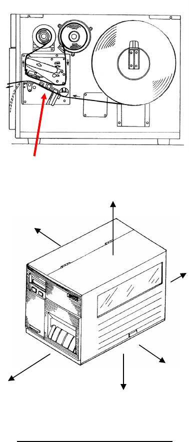
This device shall not be co-located with any other transmitting antenna.
The distance from outside the case
PN9001067 Rev B Page 1-1
Antenna Position (Cover open view)
2cm
0cm (It leaves sufficiently)
18cm
6cm
12cm
9cm

CL408e/412e Quick Guide
Table of Contents
What You Get ................................................................................. 3
Controls and Indicators ................................................................... 4
Operator Panel ................................................................... 4
LED Indicators .................................................................... 4
Adjustments ........................................................................ 4
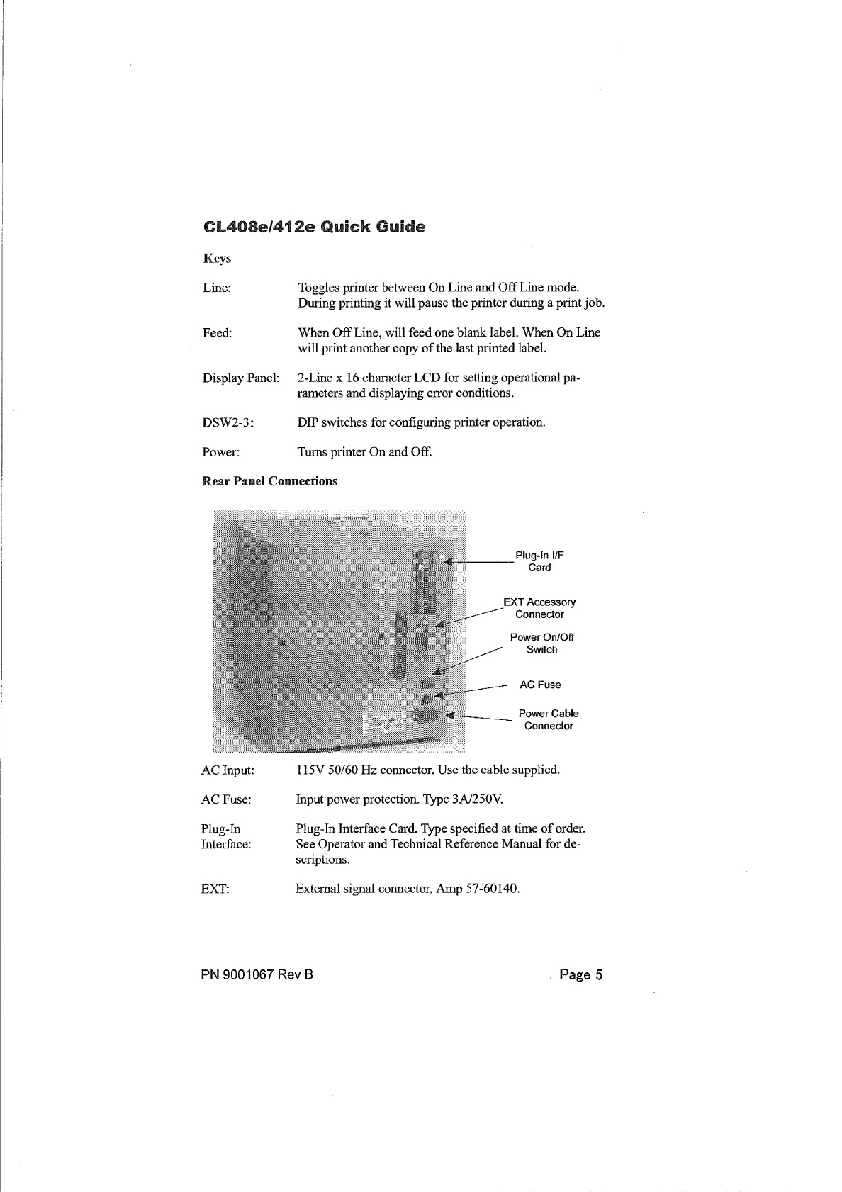
Keys ..................................................................................... 5
Rear Panel Connections ..................................................... 5
Initial Setup ..................................................................................... 6
Connecting the Printer ........................................................ 6
Printing a Test Label ........................................................... 7
Configuring the Printer ........................................................ 8
Computer Connections ....................................................... 8
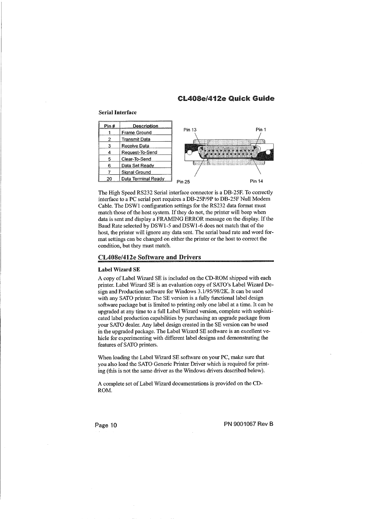
CL408e/412e Software and Drivers ................................................. 10
Label Wizard SE ................................................................. 10
Windows Drivers ................................................................. 11
What to do if it will not print ............................................................... 11
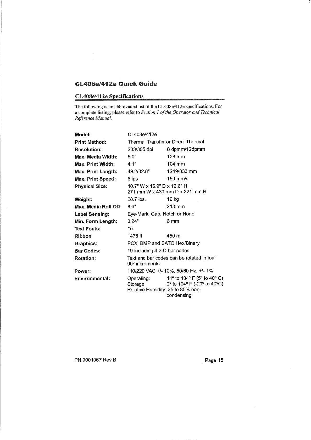
CL408e/412e Specifications ............................................................ 15
Media and Supplies ......................................................................... 16
Options ............................................................................................ 16
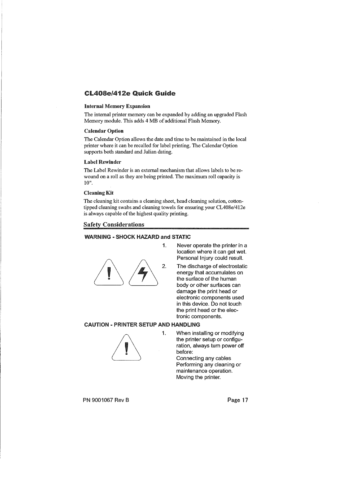
Safety Considerations ...................................................................... 17
Safety Information ............................................................................ 18
This Quick Guide was prepared to get you up and running quickly. It will
enable you to get your new SATO CL408e/412e installed and printing
with a minimum of effort. However, it is recommended that you familiarize
yourself with the contents of the CL408e/412e Operator and Technical
Reference Manual for detailed descriptions so you will be able to
properly use the printer to its full potential.
PN9001067 Rev B Page 2
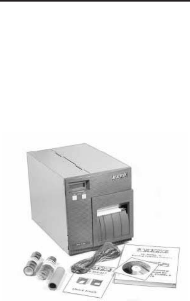
What You Get
The CL408e/412eThermal Transfer printer comes packedina protective
carton. Includedin the cartonarethefollowing items:
•CL408e/412ePrinter
•Quick Guide
•Operator andTechnical ReferenceManual
•HeadCleaningSheet
•SampleRibbons andRibbon Take-UpCore
•Power Cable
•Test PrintoutLabels
•Label WizardSE CD-ROM
After takingthe CL408e/412efromthecartonandremoving theprotective
plastic cover, it is ready for installation.
PN 9001067 Rev B Page 3
CL408e/412e Quick Guide
Controls and Indicators
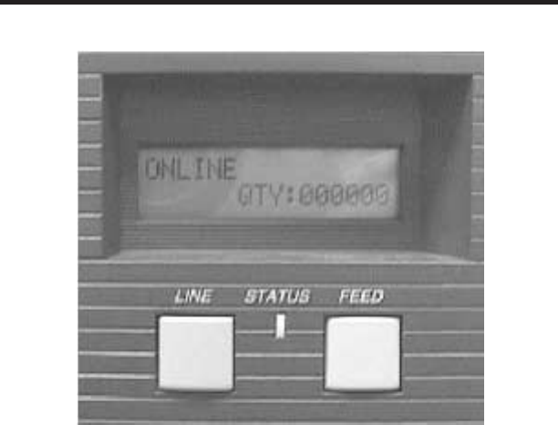
Operator Panel
LED Indicators
Status: Dark whenOff Line
Green whenprinter is On Line.
Redwhenanerror conditionexists.
LCD Display: Illuminatedwhenpower is applied.
Adjustments (controls behindfrontpanel)
Print: Adjusts printdarkness.
Offset: Adjusts amountof back/forwardfeedfor dis-
pense/cut/tear-off position.
Pitch: Adjusts homepositionof thelabel +/- 3.75 mm. Affects
stoppositionof label, printposition anddispense/cut po-
sition.
DSW2-3: Sets printer configuration
Page 4 PN 9001067 Rev B
CL408e/412e Quick Guide

Initial Set-Up
ConnectingthePrinter
1. Locatea suitablespotfor theprinter. Itshouldbewithin 6 ft. of the
hostif usinganIEEE1284 Parallel interfaceor within35 ft. if using a
High SpeedRS232 interface. For other types of Plug-Ininterface
cards, see theOperator andTechnical ReferenceManual. Makesure
thereis adequateroom aboveandto therightof theprinter for thela-
bel access door to swingopen.
2. PlugtheAC cableprovidedintotheback of theprinter andconnect
to a suitable 115VAC outlet.
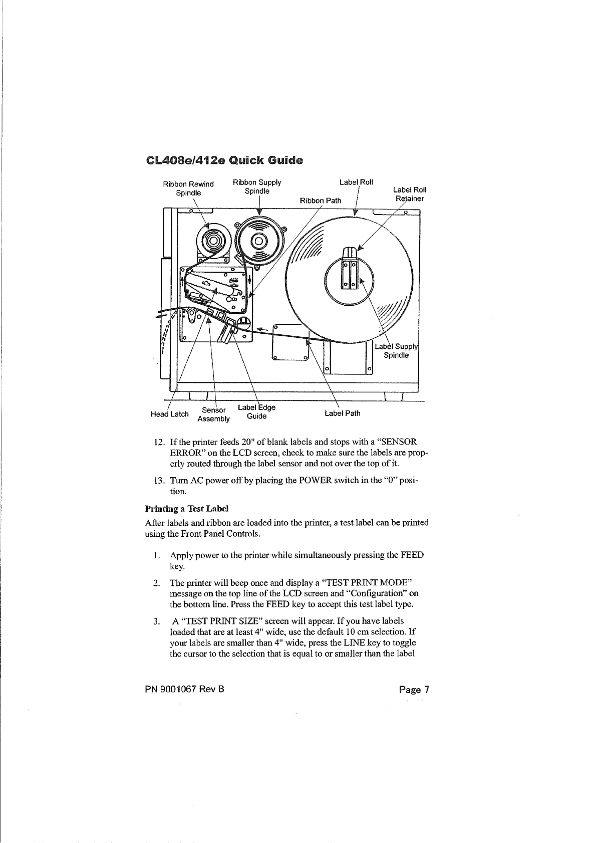
3. Opentheprintheadandloadtheribbon usingtheribbonrouting
guidelocatedontheinsideof the topcover. Besuretopositionthe
ribbonroll correctly ontheRibbonSupply Spindleandplacethe
sparetake-upcoreontheTake-UpSpindle. Tapethefreeendof the
ribbonto thetake-upcoresothatitwill take-upwhenrotatingina
counter clockwisedirection.
4. Placethelabel roll ontheLabel Supply Spindleandpushthegreen
Label Roll Retainer on the spindleuntil it pushes the label roll all the
way totheinsideof theprinter. Thelabels shouldcomeoff the bot-
tomof theroll (labels woundface-inontheroll).
5. Routethelabels as indicatedby the label routingdiagramon the in-
sideof thetopcover. Thelabels shouldgo under theplastic guide,
throughtheLabel Sensor Assembly, under the printheadandout the
front of theprinter. PositiontheLabel EdgeGuide towardtheinside
of theprinter until itbarely contacts theoutsideedgeof thelabels.
6. ClosethePrint HeadLatchandthenthesideaccess door last.
7. Select the proper label sensingmethodusingthefrontpanel DIP
switches. The DIP switchfunction chartis locatedontheinsideof
thefrontcover. Theprinter comes fromthefactory set for label gap
detection (DSW2-2, DSW3-3 both OFF). NotethattheOFF position
for theDSW switches is downandtheON positionup.
8. Apply power by placingthefrontpanel Power switchin the “1" posi-
tion.
9. The Power andOn-Line LEDs shouldbeilluminatedandONLINE
shouldbedisplayedontheLCD.
10. Press theLINE key once. TheOnLineLED shouldgo outand
OFFLINE shouldbedisplayedontheLCD.
11. Press theFEED key once. Theprinter shouldfeedout onelabel and
stop.
Page 6 PN 9001067 Rev B
CL408e/412e Quick Guide
CL408e/412e Quick Guide
Safety Information
PN9001067 Rev B Page 18
CL408e/412e Quick Guide
Safety Information
PN9001067 Rev B Page 19
CL408e/412e Quick Guide
Safety Information
PN9001067 Rev B Page 20
CL408e/412e Quick Guide
Safety Information
PN9001067 Rev B Page 21