Sato SATOTR3 RFID Reader/Writer Module Transmitter User Manual Install 2
Sato Corporation RFID Reader/Writer Module Transmitter Install 2
UserManual.wiki
>
Sato
>
SATOTR3 User Manual
>
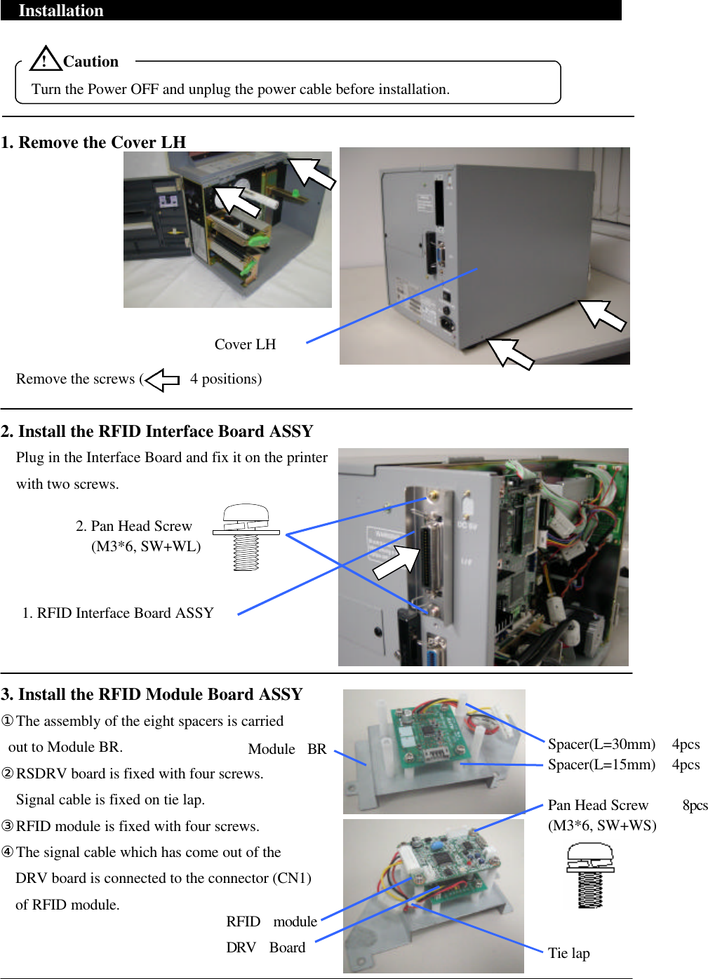
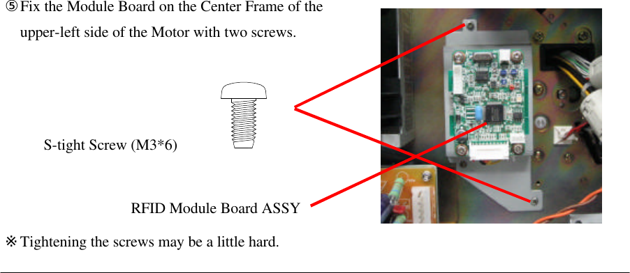
Installation Manual 1
Contents
1.
Installation Manual 1
2.
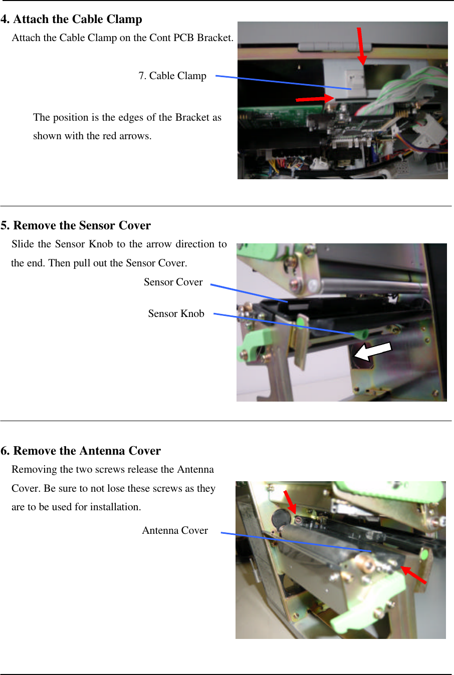
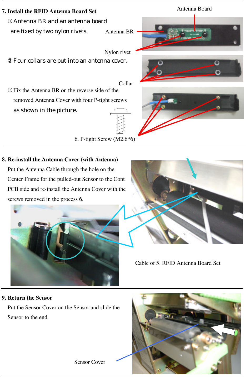
Installation Manual 2
Installation Manual 1
Navigation menu
Upload a User Manual
Namespaces
Wiki Guide
HTML
PDF
Info
Views
User Manual
Discussion / Help
Navigation