Sato SATOTR3 RFID Reader/Writer Module Transmitter User Manual Install 2
Sato Corporation RFID Reader/Writer Module Transmitter Install 2
Sato >
Contents
- 1. Installation Manual 1
- 2. Installation Manual 2
Installation Manual 1
Installation
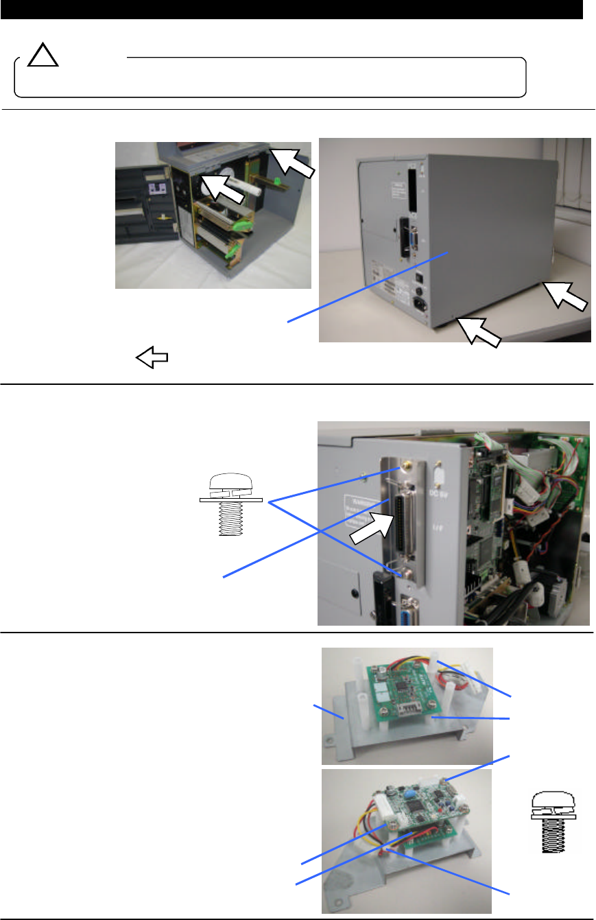
Turn the Power OFF and unplug the power cable before installation.
1. Remove the Cover LH
Remove the screws ( 4 positions)
2. Install the RFID Interface Board ASSY
Plug in the Interface Board and fix it on the printer
with two screws.
3. Install the RFID Module Board ASSY
①The assembly of the eight spacers is carried
out to Module BR.
②RSDRV board is fixed with four screws.
Signal cable is fixed on tie lap.
③RFID module is fixed with four screws.
④The signal cable which has come out of the
DRV board is connected to the connector (CN1)
of RFID module.
! Caution
Cover LH
1. RFID Interface Board ASSY
2. Pan Head Screw
(M3*6, SW+WL)
Spacer(L=30mm) 4pcs
Spacer(L=15mm) 4pcs
Pan Head Screw 8pcs
(M3*6, SW+WS)
Tie lap
RFID module
DRV Board
Module BR
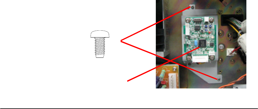
⑤Fix the Module Board on the Center Frame of the
upper-left side of the Motor with two screws.
※Tightening the screws may be a little hard.
RFID Module Board ASSY
S-tight Screw (M3*6)
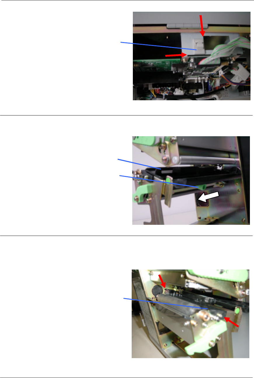
4. Attach the Cable Clamp
Attach the Cable Clamp on the Cont PCB Bracket.
5. Remove the Sensor Cover
Slide the Sensor Knob to the arrow direction to
the end. Then pull out the Sensor Cover.
6. Remove the Antenna Cover
Removing the two screws release the Antenna
Cover. Be sure to not lose these screws as they
are to be used for installation.
Sensor Cover
Antenna Cover
7. Cable Clamp
The position is the edges of the Bracket as
shown with the red arrows.
Sensor Knob
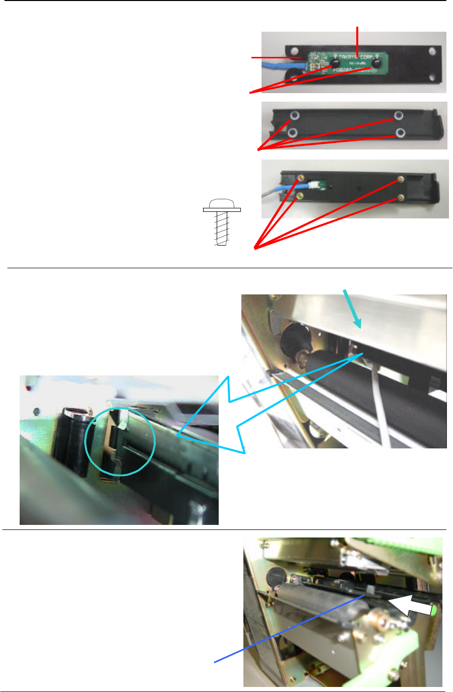
7. Install the RFID Antenna Board Set
①Antenna BR and an antenna board
are fixed by two nylon rivets.
②Four collars are put into an antenna cover.
③Fix the Antenna BR on the reverse side of the
removed Antenna Cover with four P-tight screws
as shown in the picture.
8. Re-install the Antenna Cover (with Antenna)
Put the Antenna Cable through the hole on the
Center Frame for the pulled-out Sensor to the Cont
PCB side and re-install the Antenna Cover with the
screws removed in the process 6.
9. Return the Sensor
Put the Sensor Cover on the Sensor and slide the
Sensor to the end.
Antenna BR
6. P-tight Screw (M2.6*6)
Cable of 5. RFID Antenna Board Set
Sensor Cover
Nylon rivet
Collar
Antenna Board
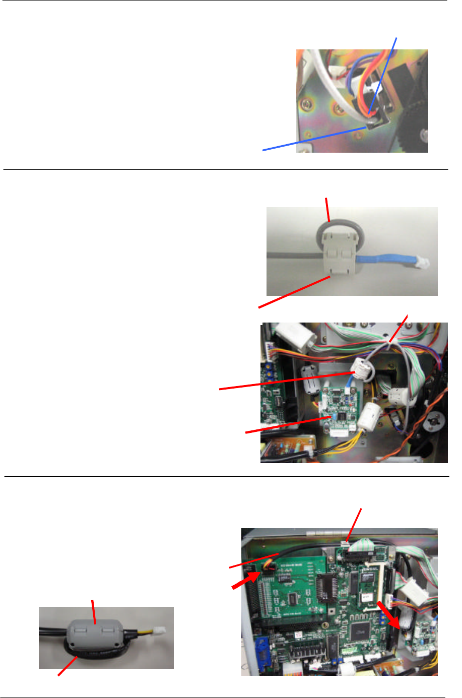
10. Fix the Antenna Cable on the Sensor
Remove the Spring on the end of the Sensor
from the Cont PCB side. Fix the Antenna Cable
on the bottom of the Sensor with the removed
Spring.
Confirm that the Cable does not get jammed by
sliding the Sensor.
11. Connect the Antenna Cable
①Ferrite core is attached to an antenna cable.
②Connect the Antenna Cable to the connector at
the bottom of the Module Board and fix its route
with the Clamp.
12. Connect the RFID Cable SET
①Ferrite core is attached to RFID cable set.
②Connect the Interface Board and the Module
Board via the RFID Cable and fix its route with
the Cable Clamp.
Spring
Sensor
RFID Module Board
Clamp
Antenna Cable
Cable
Clamp
RFID Cable Set
Ferrite core
Cable 1 turn
Cable 1 turn
Ferrite core