Users Manual

User’s Manual
TR3-C302
Manual No.TDR-MNL-C302-EN-100

Manual No.TDR-MNL-C302-EN-100
TAKAYA RFID TR3 Series
Introduction
Thank you for purchasing a TR3-C302 RFID READER/WRITER.
Be sure to read this manual before using the product.
After reading it, store the manual in a convenient place for future reference.
Manual No.TDR-MNL-C302-EN-100
TAKAYA RFID TR3 Series
Regulations and Standards
FCC
This product is conform to the FCC standards.
FCC Rules (Federal Communications Commission)
This product complies with Part 15 Subpart C of the FCC Rules.
FCC NOTICE
This device complies with part 15 of the FCC Rules. Operation is subject to the following two
conditions:
(1) This device may not cause harmful interference.
(2) This device must accept any interference received, including interference that may cause
undesired operation.
FCC WARNING
Changes or modifications not expressly approved by the party responsible for compliance could void
the user's authority to operate the equipment.
The following sentence has to be displayed on the outside of the device in which the transmitter module
is installed : “Contains FCC ID: ****************”
Japan Radio Law
Equipment using high frequencies: Inductive Reading/Writing Communications Equipment
Conforming standards: Inductive Reading/Writing Communications Equipment;
Standard: ARIB STD-T82
Tags
This product can communicate the standard tags of ISO/IEC15693 and ISO/IEC18000-3(Mode1,3),
ISO/IEC14443A, ISO/IEC14443B, ISO/IEC 18092(212kbps Passive Mode, FeliCa).
Supports
Manufacturer
Tag-it HF-I
Texas Instruments
my-d
Infineon Technologies
I・CODE SLI, Mifare Ultralight
NXP Semiconductors
MB89R118
FUJITSU Japan
Felica
Sony Corporation
RoHS is support
Restriction of Hazardous Substances
Waste
Dispose of the Products as industrial waste.
Manual No.TDR-MNL-C302-EN-100
TAKAYA RFID TR3 Series
Safety Precautions
The following symbols are used in this manual to indicate precautions that must be observed to ensure safe use of
this product. The precautions provided here contain important safety information. Be sure to observe these
precautions.
The following signal words are used in this manual.
Failure to comply with a WARNING may result in serious injury or
death.
Failure to comply with a CAUTION may result in injury to the
operator, or damage to the items involved.
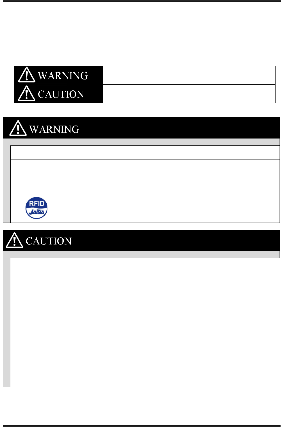
Be sure to observe the following precautions to ensure safe use of the Products.
Decomposition of this product and cable, repair, remodeling, please strictly prohibited. There is the
possibility of fire or electric shock injuries.
This product is using the RFID reader writer radio equipment. Therefore, depending on where the
applications you use may affect medical equipment. To minimize the impact of medical equipment for use,
please observe the following countermeasure. The Japan Automatic Identification Systems Association
(JAISA) guidelines are as follows: RFID antennas from implanted cardiac pacemakers or other medical
devices please 22cm apart. We recommend that you paste "RFID sticker" at equipment.
Be sure to observe the following precautions to ensure safe use of the Products.
Installation and storage environment
1. Do not use the Products in sunlight.
2. Do not use the Products in environment of spray of water, oil or chemicals.
3. Do not use the Products in environments with flammable, explosive, or corrosive gasses.
4. Do not use the Products in environment of hot humid.
5. Do not use the Products in environment of vibration or shock.
6. Do not use the Products in environment of condensation.
7. Do not use the Products in environment of around the metal is covered.
8. Do not use the Products in environment of high temperature.
9. Do not use the Products in environment that has a device that generates magnetic field and shock voltage.
10. Do not use the Products in unstable place.
11. If there is failure, discontinue use immediately, please contact us or the distributor.
Installation
1. Turn off the power before installation or removing.
2. The following effects may not work correctly.
・ Near 13.56MHz radio device
・ Near speakers , Inverter, motor and Plasma Display
3. The communication range may vary due to environment and conditions.
← RFID Sticker

Manual No.TDR-MNL-C302-EN-100
TAKAYA RFID TR3 Series
Contents
1 Product Overview ...................................................................................................... 1
1.1 Features .............................................................................................................................................. 1
2 Names of Parts and Functions ..................................................................................... 2
2.1 TR3-C302 ............................................................................................................................................ 2
2.2 Antenna .............................................................................................................................................. 3
2.2.1 TR3-A202 ........................................................................................................................................ 3
2.2.2 TR3-A302 ........................................................................................................................................ 4
2.2.3 TR3-A401 ........................................................................................................................................ 4
3 Installation and connection ......................................................................................... 5
3.1 Installation into a host device .............................................................................................................. 5
3.2 Antenna installation into a host device ................................................................................................. 6
3.2.1 Screw holes ...................................................................................................................................... 6
3.2.2 Guide ............................................................................................................................................... 6
3.3 Connection .......................................................................................................................................... 7
3.3.1 Attaching the Cable and Antenna ........................................................................................................ 7
3.3.2 Direct connection to the Host Device Interface .................................................................................... 7
3.3.3 Using the interface board to connect to the Host Device Interface .......................................................... 8
4 Specifications ............................................................................................................. 9
4.1 TR3-C302 ............................................................................................................................................ 9
4.2 Antenna ............................................................................................................................................ 14
4.2.1 TR3-A202 ...................................................................................................................................... 14
4.2.2 TR3-A302 ...................................................................................................................................... 15
4.2.3 TR3-A401 ...................................................................................................................................... 16
4.3 Cable ................................................................................................................................................. 17
4.3.1 TR3-AC-1A-*** ............................................................................................................................. 17
4.3.2 TR3-AC-2A-*** ............................................................................................................................. 17
5 Maintenance ............................................................................................................ 18
Revision History ............................................................................................................. 19
Manual No.TDR-MNL-C302-EN-100
1 Product Overview
1.1 Features
TAKAYA RFID TR3 Series
1 Product Overview
1.1 Features
This product uses the 13.56MHz frequency. This product is the electromagnetic induction type non-contact
IC can read and write RFID tag data.
This Product is designed to be embedded and integrated within OEM devices and finished products such as label
printers, cashless payment terminals or any other device that can benefit from integrated RFID capabilities.
■ Conform to international standards
ISO/IEC15693 and ISO/IEC18000-3(Mode1, 3) , ISO/IEC14443A, ISO/IEC14443B,
ISO/IEC 18092(212kbps Passive Mode, FeliCa) is supports.
■ Rich Products
Various interface RS-232C, USB, TCP/IP.
Antennas of various sizes
■ Software
TR3-series common communication protocol
Software Development Kit
■ Useful
Continuous inventory mode
UID of the tag automatically sends Host Device.
RDLoop mode
UID or User Data of the tag automatically sends Host Device.
For more information please refer to the TR3-PROTOCOL manual.
■ Environmentally
EU RoHS(2002/95/EC) Support
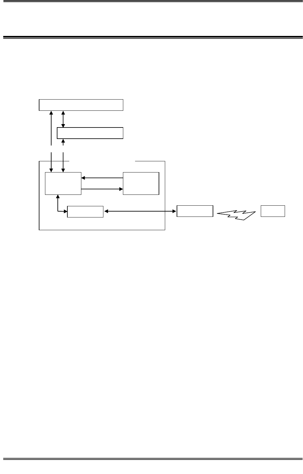
Antenna
CPU
Memory
RF-ASIC
READER/WRITER
Load Settings
Save Settings
Interface
Tags
Host Device Interface
RS-232C、LAN(TCP/IP)、USB
Communications
UART(CMOS Level)
Manual No.TDR-MNL-C302-EN-100
2 Names of Parts and Functions
2.1 TR3-C302
TAKAYA RFID TR3 Series
2 Names of Parts and Functions
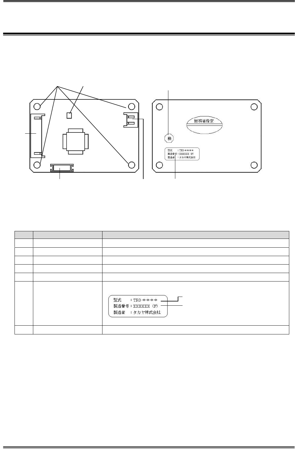
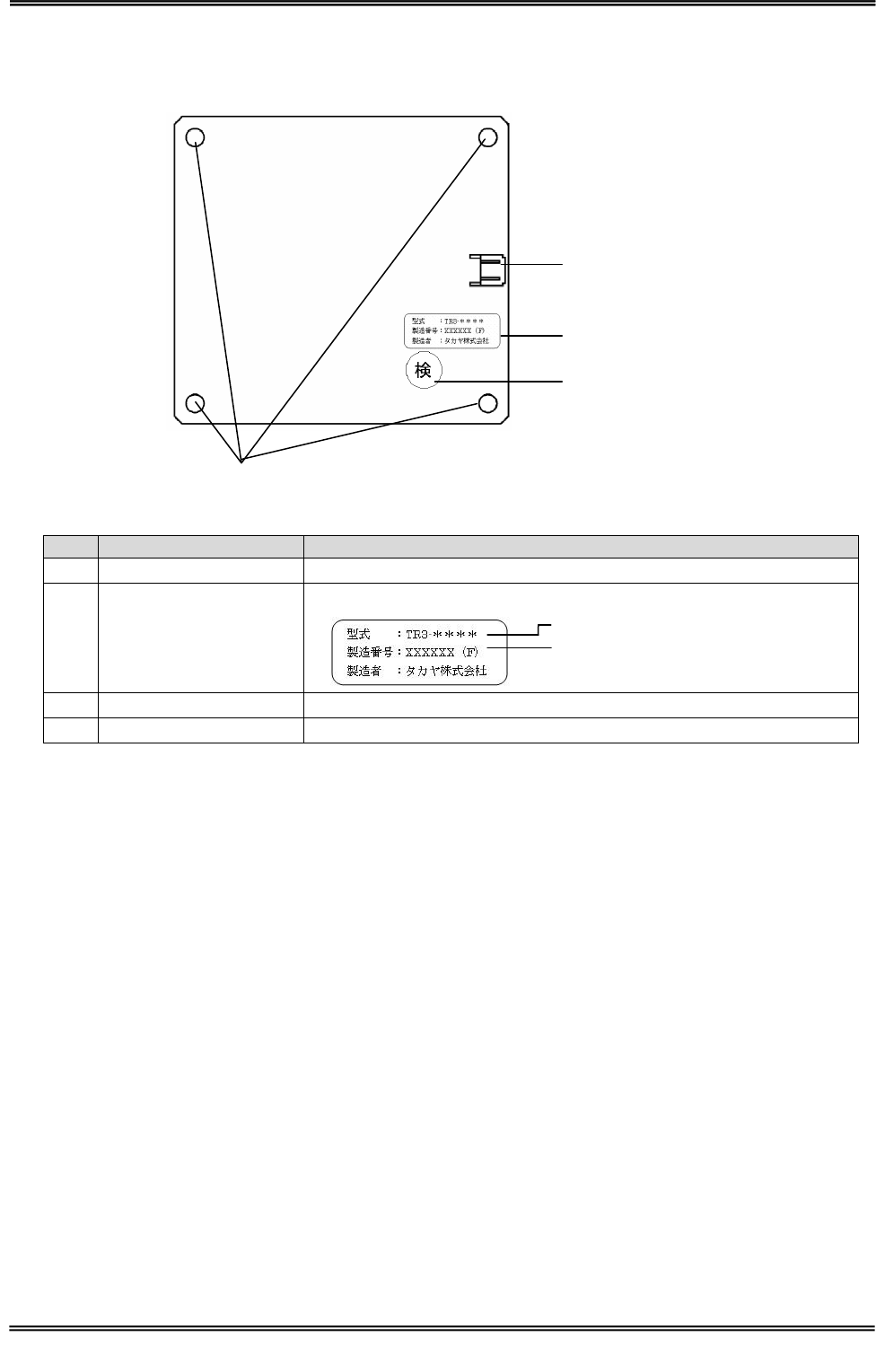
2.1 TR3-C302
No
Name
Description
①
CN1
This connector is for connection to the host.
②
CN2
Connect the antenna cable.
③
CN3
Connect the buzzer control cable.
④
LED1
Displays the status of this product.
⑤
Inspection mark
⑥
Nameplate
Production numbers, will be 8-digit serial number.
⑦
Screw holes
M3 holes
⑦
④
①
③
②
⑥
⑤
Model Name
Serial number:********(F)
Manual No.TDR-MNL-C302-EN-100
2 Names of Parts and Functions
2.2 Antenna
TAKAYA RFID TR3 Series
2.2 Antenna
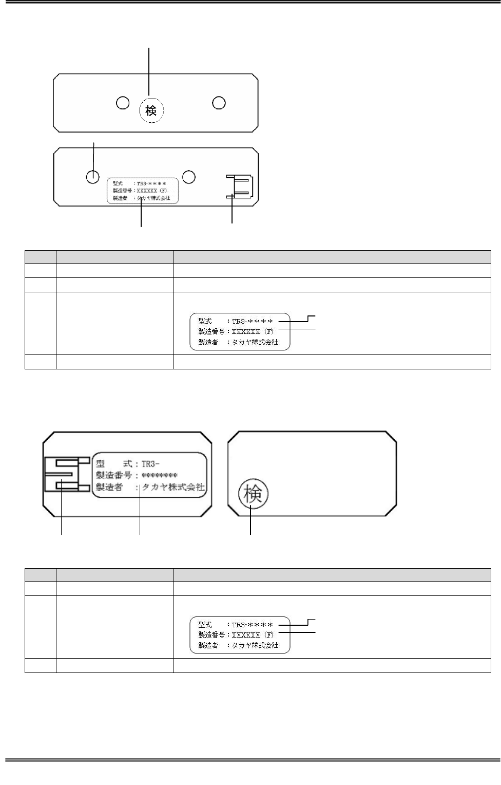
2.2.1 TR3-A202
No
Name
Description
①
CN1
Connect the antenna cable.
②
Nameplate
Production numbers, will be 8-digit serial number.
③
Inspection mark
④
Screw holes
M3 holes
④
①
②
③
Model Name
Serial number:********(F)
Manual No.TDR-MNL-C302-EN-100
2 Names of Parts and Functions
2.2 Antenna
TAKAYA RFID TR3 Series
2.2.2 TR3-A302
No
Name
Description
①
Inspection mark
②
Screw holes
M3 holes
③
Nameplate
Production numbers, will be 8-digit serial number.
④
CN1
Connect the antenna cable.
2.2.3 TR3-A401
No
Name
Description
①
CN1
Connect the antenna cable.
②
Nameplate
Production numbers, will be 8-digit serial number.
③
Inspection mark
②
③
④
①
Model Name
Serial number:********(F)
①
②
③
Model Name
Serial number:********(F)
Manual No.TDR-MNL-C302-EN-100
3 Installation and connection
3.1 Installation into a host device
TAKAYA RFID TR3 Series
3 Installation and connection
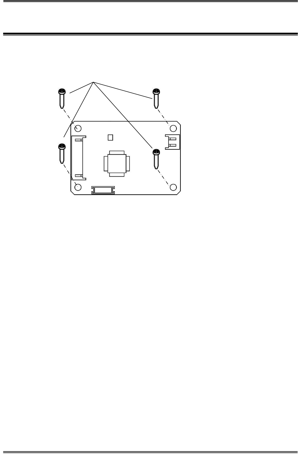
3.1 Installation into a host device
Four, M3 holes
Manual No.TDR-MNL-C302-EN-100
3 Installation and connection
3.2 Antenna installation into a host device
TAKAYA RFID TR3 Series
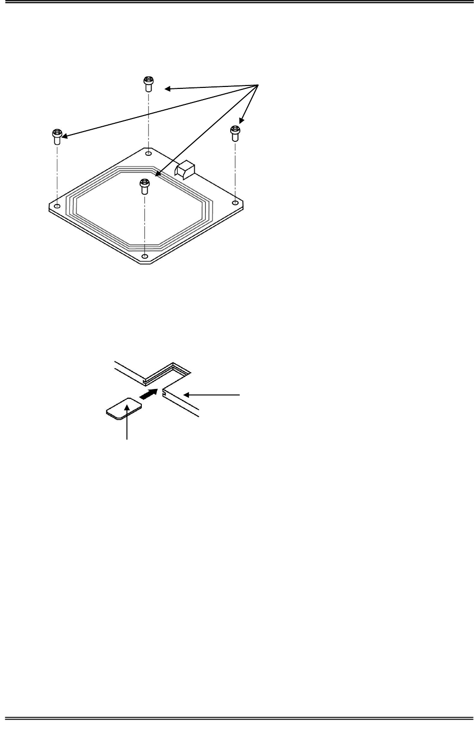
3.2 Antenna installation into a host device
3.2.1 Screw holes
3.2.2 Guide
TR3-A401 is recommended that you set up a guide on fixed-like the figure below.
TR3-A401
M3 Screw
Host Device
Manual No.TDR-MNL-C302-EN-100
3 Installation and connection
3.3 Connection
TAKAYA RFID TR3 Series
3.3 Connection
This product will connect with the antenna and antenna cables.
This product connects with Host Device that direct connection or connect using our interface.
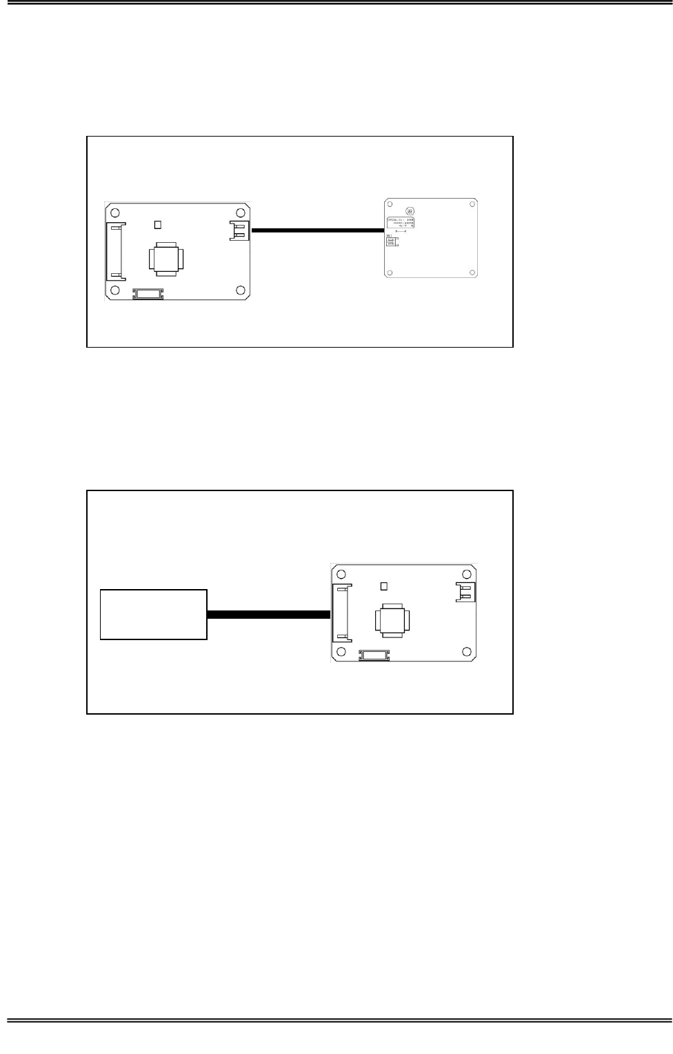
3.3.1 Attaching the Cable and Antenna
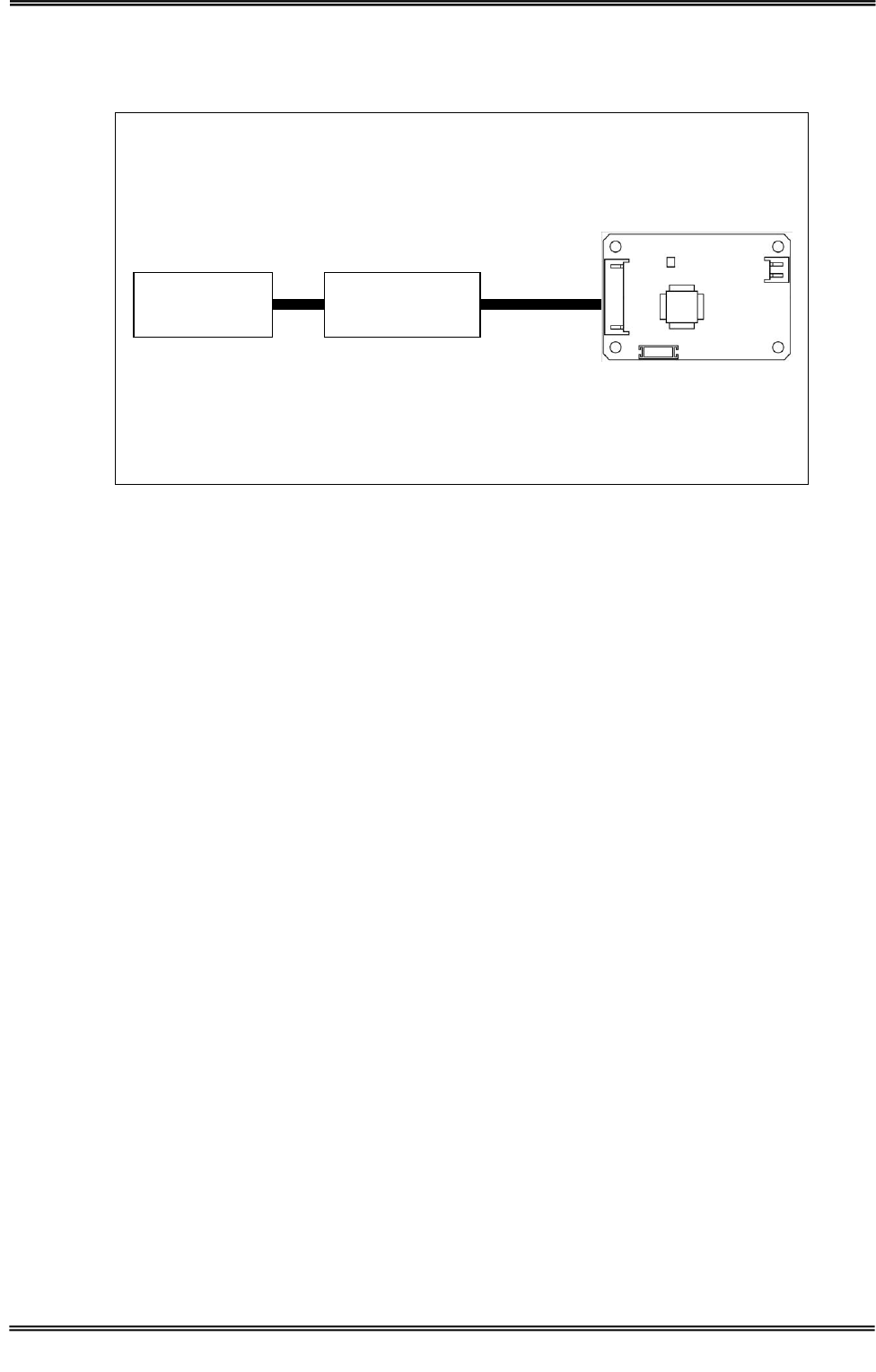
3.3.2 Direct connection to the Host Device Interface
Please prepare to the interface harness.
Host Device
Host Device
Interface harness
TR3-C302
TR3-C302
Antenna
Antenna Cable
Host Device
Interface
Manual No.TDR-MNL-C302-EN-100
3 Installation and connection
3.3 Connection
TAKAYA RFID TR3 Series
Host Device
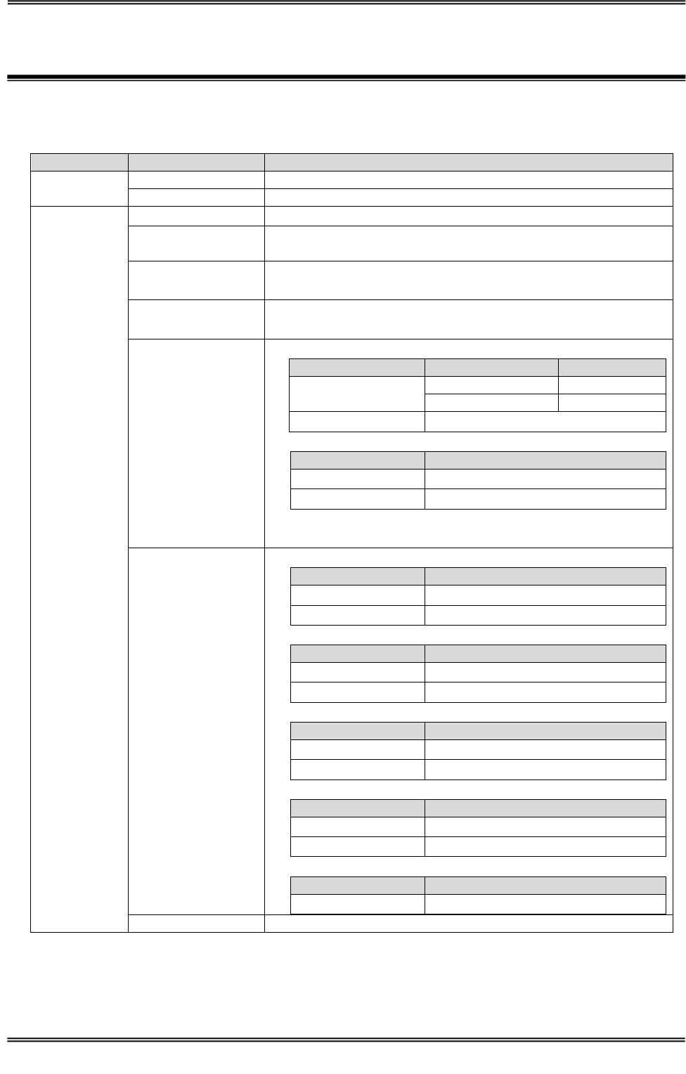
3.3.3 Using the interface board to connect to the Host Device Interface
Interface board, please contact us.
TR3-C302
Interface Cable
Interface board
Interface harness
Host Device
Interface
Manual No.TDR-MNL-C302-EN-100
4 Specifications
4.1 TR3-C302
TAKAYA RFID TR3 Series
4 Specifications
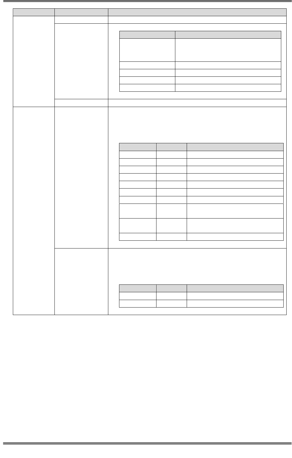
4.1 TR3-C302
■ Specifications
Specifications
Item
Parameter
Applicable
Standards
Japan Radio Law
ARIB STD-T82
RoHS
EU RoHS(2002/95/EC) Supports
Radio
Frequency
Carrier frequency
13.56MHz ±50ppm(Ta=25℃) or less
Transmit power or
power range
200mW ± 20%(Ta=25℃, VCC=5.0V)
Standards
ISO/IEC 15693、ISO/IEC18000-3(Mode1)
ISO/IEC 14443A、ISO/IEC 14443B、ISO/IEC 18092(FeliCa)
Tags
Tag-it HF-I, my-d, I・CODE SLI, MB89R118
Mifare Ultralight, FeliCa (※1)
Data rate
・ISO/IEC 15693,ISO/IEC18000-3(Mode1)
Speed
Data rate
Product⇒Tag
1/4
26.48kbps
1/256
1.65kbps
Tag⇒Product
26.69kbps
・ISO/IEC18000-3(Mode3)
Parameter
Product⇒Tag
26.7kbps~100kbps
Tag⇒Product
53kbps
・ISO/IEC 14443A, ISO/IEC 14443B 106 kbps
・ISO/IEC 18092(Passive Mode) 212kbps
Modulation
・ISO/IEC 15693,ISO/IEC18000-3(Mode1)
Parameter
Product⇒Tag
ASK 10% / ASK 100%
Tag⇒Product
ASK
・ISO/IEC18000-3(Mode3)
Parameter
Product⇒Tag
ASK 10%
Tag⇒Product
ASK
・ISO/IEC 14443A
Parameter
Product⇒Tag
ASK 100%
Tag⇒Product
ASK
・ISO/IEC 14443B
Parameter
Product⇒Tag
ASK 10%
Tag⇒Product
ASK
・ISO/IEC 18092(Passive Mode)
Parameter
Product⇒Tag
ASK 10%
Anti-collision
Support
※1:Tag-it HF-I is a registered trademark of Texas Instruments Incorporated.
my-d is a registered trademark of Infineon Technologies AG.
I・CODE SLI, Mifare Ultralight are registered trademarks of NXP Semiconductors.
MB89R118 is a registered trademark of FUJITSU Japan.
Felica is a registered trademark of Sony Corpration.
Manual No.TDR-MNL-C302-EN-100
4 Specifications
4.1 TR3-C302
TAKAYA RFID TR3 Series
Specifications
Item
Parameter
Controll
Command
Please refer to the TR3-Protocol-Manual.
Host Interface
UART(CMOS)
Item
Parameter
Speed
9600bps
19200bps(※2)
38400bps
Data bits
8
Parity
None
Stop bit
1
Flow control
None
LED1
1pc (3 colors, red/green/orange)
Connector
CN1
Connector : JST S10B-PH-SM4-TB(LF)(SN)
Housing : JST PHR-10
Contact : JST SPH-002T-P0.5S
Pin assignment
Pin No.
Symbol
Function
1
VCC
Power
2
VCC
Power
3
GND
GND
4
GND
GND
5
Rx
Received data signal
6
Tx
Transmitted data signal
7
VCC2
Power output
8
IO1
Input/Output or Detection signal
output H : Detection
9
IO2
Input/Output or Trigger input
L : Trigger ON
10
IO3
Input/Output
CN2
Connector : JST S2B-PH-SM4-TB(LF)(SN)
Housing : JST PHR-2
Contact : JST SPH-002T-P0.5S
Pin assignment
Pin No.
Symbol
Function
1
RF
Analog signal
2
GND
GND
※2:initialization

Manual No.TDR-MNL-C302-EN-100
4 Specifications
4.1 TR3-C302
TAKAYA RFID TR3 Series
Specifications
Item
Parameter
Mechanical
data
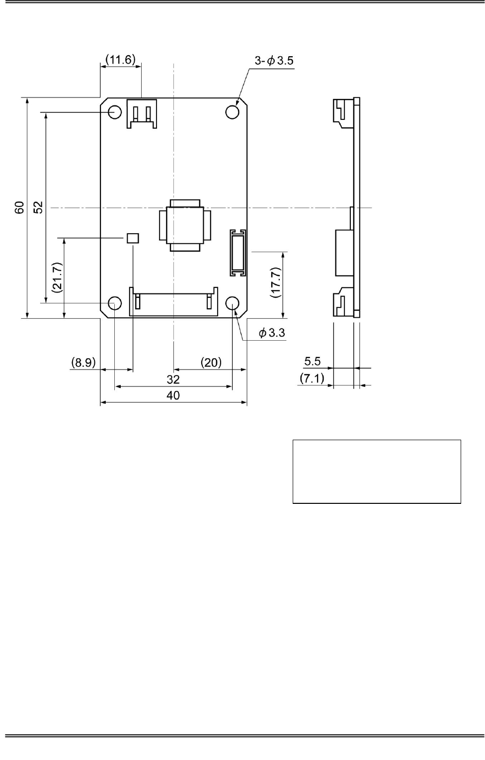
Dimensions
(W x D x H)
40 x 60 x 7.1mm
Weight
approx. 12g
Installation
M3 Screw
Screw is not included.
Electrical
data
Power
Supply Voltage
:DC+5.0V ±10%
Current consumption
:approx. 160mA
Carrier off
:approx. 35mA
Power down mode
:approx. 24mA
Consumption
:max 1.0W
Ambient
Conditions
Temperature
Operating range
0 to 55 degree
Humidity Operating
range
30 to 80%RH
Temperature
Storage range
0 to 55 degree
Humidity
Storage range
30 to 80%RH
Other
Accessories
None
Manual No.TDR-MNL-C302-EN-100
4 Specifications
4.1 TR3-C302
TAKAYA RFID TR3 Series
■ Dimensions
Unit:mm
Tolerance:±1mm
( )is Recommended Dimension
Screw hole depth:3mm
Manual No.TDR-MNL-C302-EN-100
4 Specifications
4.1 TR3-C302
TAKAYA RFID TR3 Series
■ Connections
Names
Model
Notes
Antenna
TR3-A202
TR3-A302
TR3-A401
Cable
TR3-AC-1A-***
*** puts the cable length.
9cm ~ 50cm cable are available.
TR3-AC-2A-***
*** puts the cable length.
10cm ~ 3m cable are available.
Interface board
TR3-IF-1C
RS232C interface
TR3-IF-N1
TCP/IP interface
TR3-IF-U1
TR3-IF-U1A
USB interface
■ Electrical Characteristics(CN1)
VDD=5V
Item
Condition
MIN
TYP
MAX
Unit
H input voltage
RX,IO1,IO2,IO3
2.5
5.0
V
L input voltage
RX,IO1,IO2,IO3
0
1.0
V
H output voltage
IOH=-5mA,-20mA
3.0
V
L output voltage
IOL=5mA,20mA
2.0
V
Pull-up resistor
25.0
50.0
100.0
kΩ
・TX, RX, IO1, IO2 and IO3 is, Pull-up resistor has been connected.
・TX, RX, IO1, IO2 and IO3 is, 100 ohm resistor has been connected.
Output port, LED is not driven. If the LED drive, please use the digital transistors.
Manual No.TDR-MNL-C302-EN-100
4 Specifications
4.2 Antenna
TAKAYA RFID TR3 Series
4.2 Antenna
4.2.1 TR3-A202
■ Specifications
Specifications
Item
Parameter
Applicable
Standards
RoHS
EU RoHS(2002/95/EC) Support
Antenna
Resonant
frequency
13.56MHz ±40kHz(Ta=25℃)
Communication
distance
Max 10cm
(Communication distance depends on the environment.)
Connector
CN1
Connector : JST S2B-PH-SM4-TB(LF)(SN)
Housing : JST PHR-2
Contact : JST SPH-002T-P0.5S
Pin assignment
Pin No.
Symbol
Function
1
RF
Analog signal
2
GND
GND
Mechanical
data
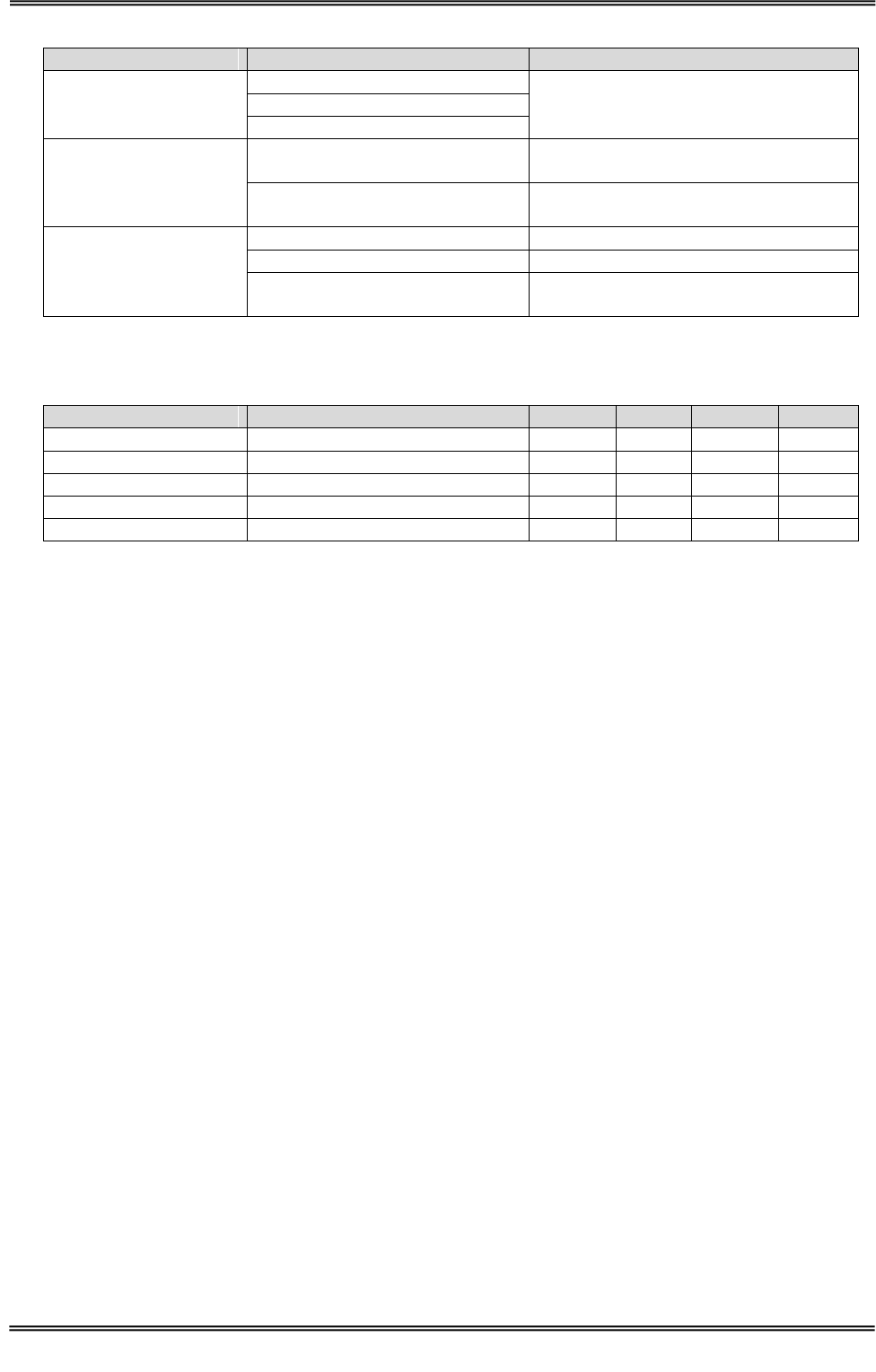
Dimensions
(W x D x H)
60 x 65 x 9.1 mm
Weight
approx. 11g
Installation
M3 Screw
Screw is not included.
Ambient
Conditions
Temperature
Operating range
0 to 55 degree
Humidity Operating
range
30 to 80%RH
Temperature
Storage range
0 to 55 degree
Humidity
Storage range
30 to 80%RH
Other
Accessories
RFID Sticker 1 sheet
Model Name : SEL41400L
■ Dimensions
Unit:mm
Tolerance:±1mm
Substrate thickness : 1.6mm
Manual No.TDR-MNL-C302-EN-100
4 Specifications
4.2 Antenna
TAKAYA RFID TR3 Series
4.2.2 TR3-A302
■ Specifications
Specifications
Item
Parameter
Applicable
Standards
RoHS
EU RoHS(2002/95/EC) Support
Antenna
Resonant
frequency
13.56MHz ±40kHz(Ta=25℃)
Communication
distance
Max 7cm
(Communication distance depends on the environment.)
Connector
CN1
Connector : JST S2B-PH-SM4-TB(LF)(SN)
Housing : JST PHR-2
Contact : JST SPH-002T-P0.5S
Pin assignment
Pin No.
Symbol
Function
1
RF
Analog signal
2
GND
GND
Mechanical
data
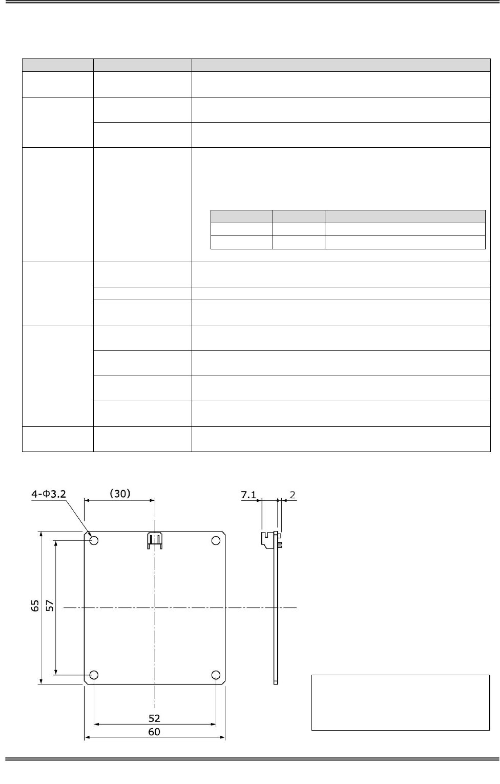
Dimensions
(W x D x H)
15 x 52.5 x 9.1 mm
Weight
approx. 3g
Installation
M3 Screw
Screw is not included.
Ambient
Conditions
Temperature
Operating range
0 to 55 degree
Humidity Operating
range
30 to 80%RH
Temperature
Storage range
0 to 55 degree
Humidity
Storage range
30 to 80%RH
Other
Accessories
RFID Sticker 1 sheet
Model Name : SEL41400L
■ Dimensions
Unit:mm
Tolerance:±1mm
Substrate thickness : 1.6mm
Manual No.TDR-MNL-C302-EN-100
4 Specifications
4.2 Antenna
TAKAYA RFID TR3 Series
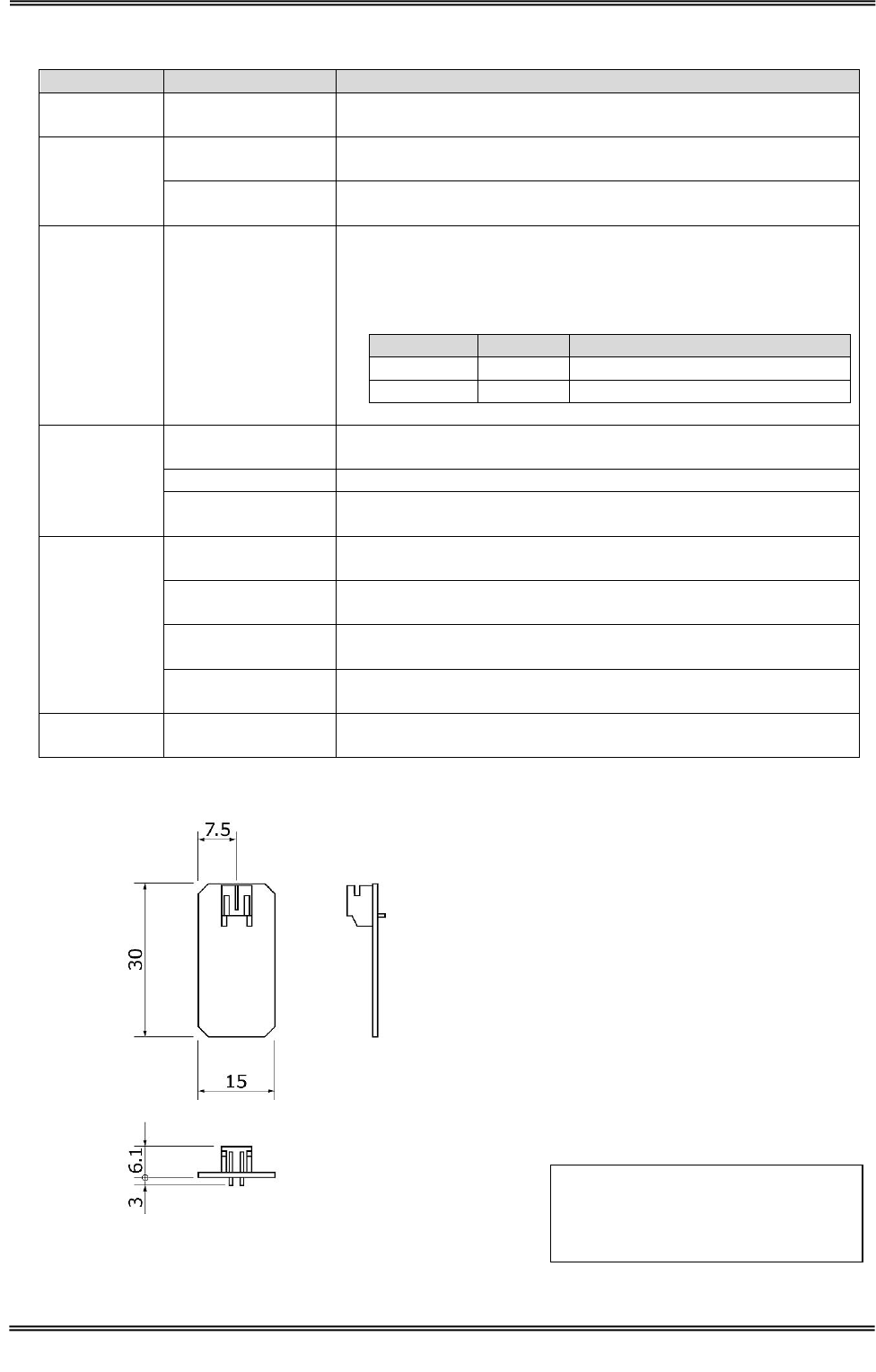
4.2.3 TR3-A401
■ Specifications
Specifications
Item
Parameter
Applicable
Standards
RoHS
EU RoHS(2002/95/EC) Support
Antenna
Resonant
frequency
13.56MHz ±40kHz(Ta=25℃)
Communication
distance
Max 5cm
(Communication distance depends on the environment.)
Connector
CN1
Connector : JST S2B-PH-K-S(LF)(SN)
Housing : JST PHR-2
Contact : JST SPH-002T-P0.5S
Pin assignment
Pin No.
Symbol
Function
1
RF
Analog signal
2
GND
GND
Mechanical
data
Dimensions
(W x D x H)
15 x 30 x 9.1 mm
Weight
approx. 2g
Installation
M3 Screw
Screw is not included.
Ambient
Conditions
Temperature
Operating range
0 to 55 degree
Humidity Operating
range
30 to 80%RH
Temperature
Storage range
0 to 55 degree
Humidity
Storage range
30 to 80%RH
Other
Accessories
RFID Sticker 1 sheet
Model Name : SEL41400L
■ Dimensions
Unit:mm
Tolerance:±1mm
Substrate thickness : 1.0mm
Manual No.TDR-MNL-C302-EN-100
4 Specifications
4.3 Cable
TAKAYA RFID TR3 Series
4.3 Cable
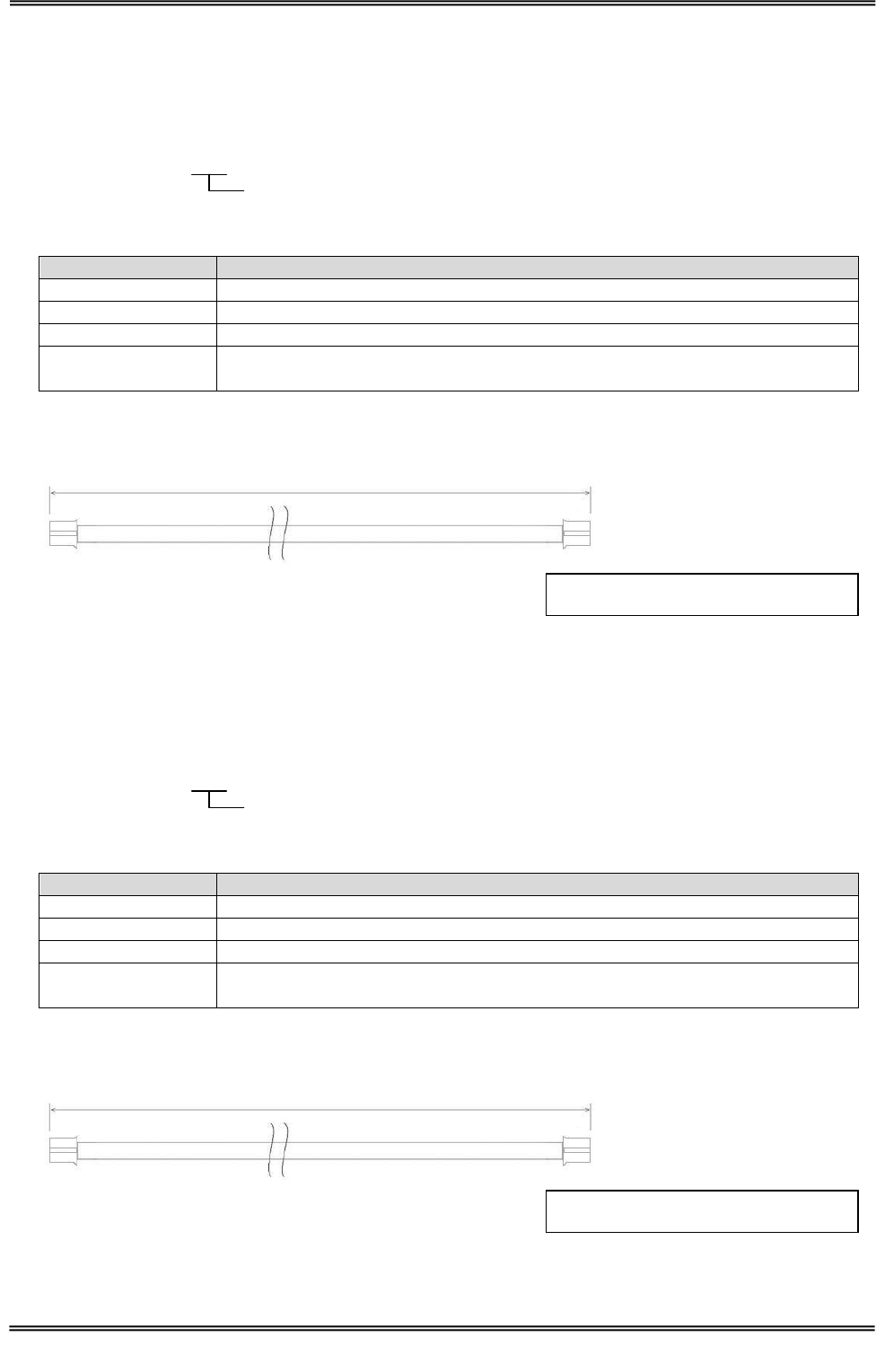
4.3.1 TR3-AC-1A-***
■ Model Name
■ Specifications
Item
Parameter
RoHS
EU RoHS(2002/95/EC) Support
Linetype
Twisted pair cable
Connector
PH-PH
Cable loss
9cm : approx. 0.061dB
50cm : approx. 0.337dB
■ Dimensions
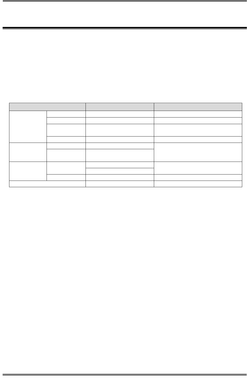
4.3.2 TR3-AC-2A-***
■ Model Name
■ Specifications
Item
Parameter
RoHS
EU RoHS(2002/95/EC) Support
Linetype
Coaxial cable 1.5D-2V
Connector
PH-PH
Cable loss
10cm : approx. 0.043dB
3m : approx. 0.255dB
■ Dimensions
( )is Recommended Dimension
(Cable length)
TR3-AC-2A-***
Enter the cable length(Unit:mm)
100~3M
( )is Recommended Dimension
(Cable length)
TR3-AC-1A-***
Enter the cable length(Unit:mm)
090~500
Manual No.TDR-MNL-C302-EN-100
TAKAYA RFID TR3 Series
5 Maintenance
This product is mainly used in electronic components and semiconductors.
Therefore, the long-term stable operation, the environment and conditions are expected to defect, as
shown below.
• Device degradation due to overvoltage and overcurrent.
• Device degradation due to high temperature and long-term stress.
• Poor contact of the connector and cause deterioration of insulation by moisture
or dust.
• Connector corrosion by corrosive gases.
In order to use this product at its best, please conduct routine or periodic inspections.
Item
Maintenance
Criteria
Ambient
conditions
Temperature
Temperature Operating range
0 to 55 degree
Humidity
Humidity Operating range
30 to 80%RH
Enclosure
rating
Check the dusty
None
Corrosive
Check the corrosion
None
Power
Input
Check the voltage
Input Voltage : DC5V±10%
Voltage
fluctuation
Check the Voltage fluctuation
Attachment
Product
Check the Screw
Checking and verifying
Check the Connector
Cable
Check the Cable break
None
Performance
Check the Performance
Work

Manual No.TDR-MNL-C302-EN-100
TAKAYA RFID TR3 Series
Revision History
Revision code
Date
Revised contents
1.00
2014/11/05
Original production