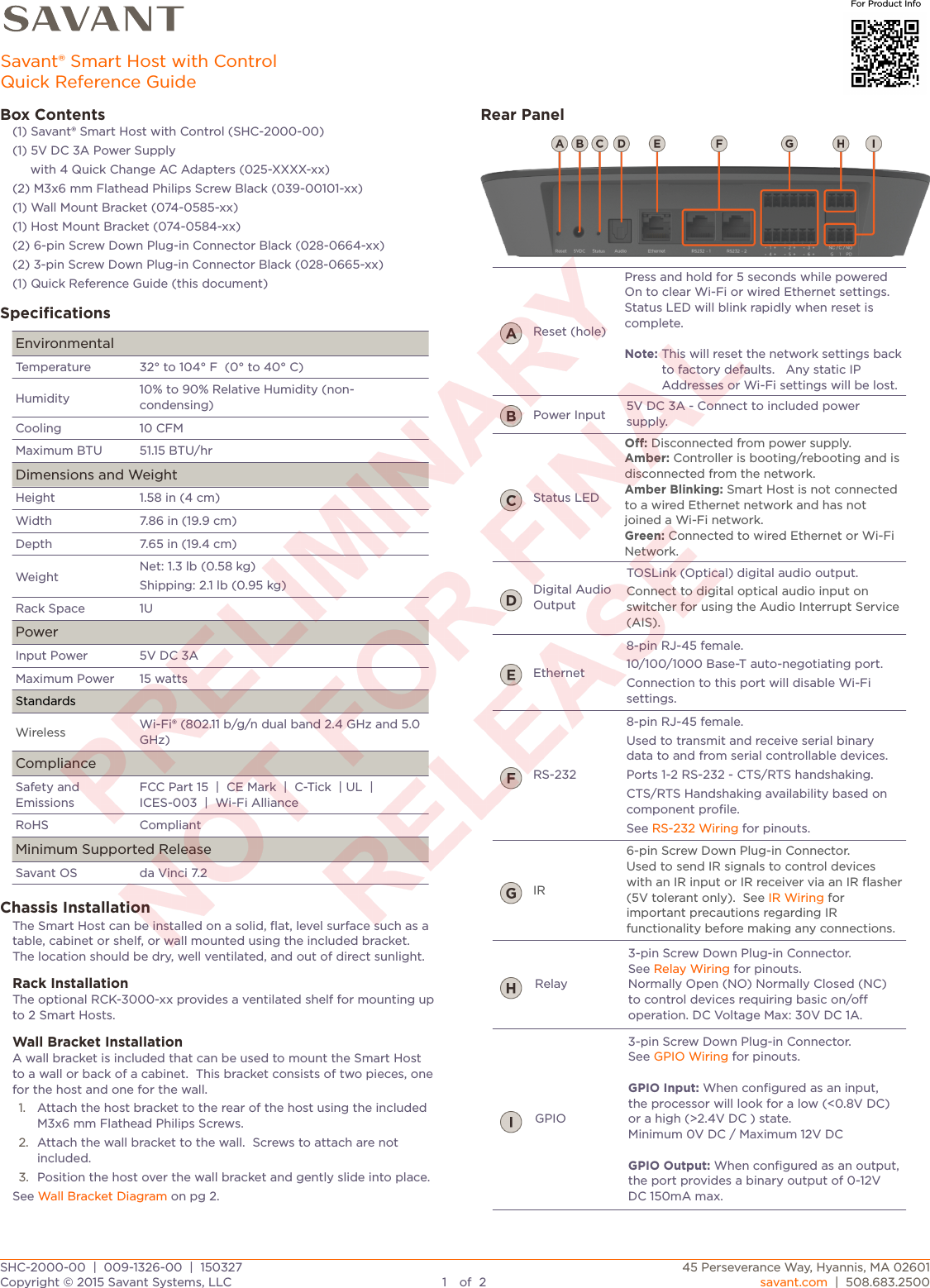
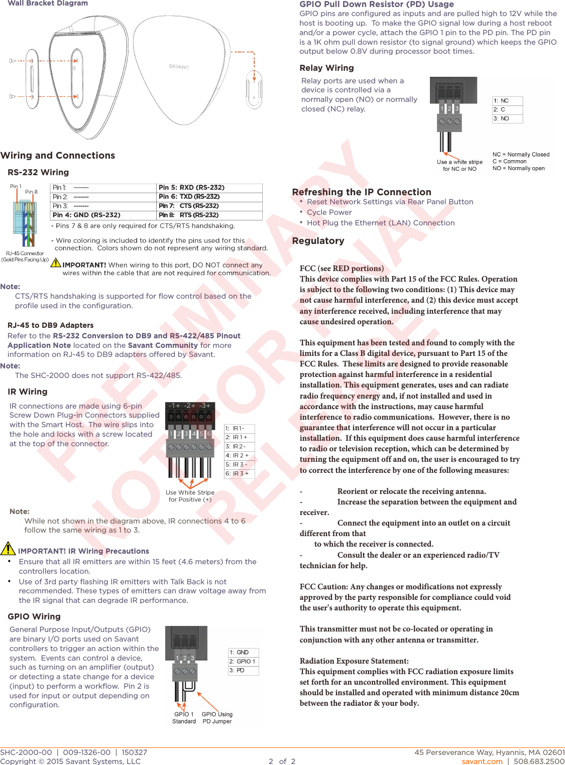
Savant Systems SHC2000 Smart Host Controller User Manual 009 1326 00 Savant Smart Host SHC 2000 QRG

Savant Systems LLC Smart Host Controller 009 1326 00 Savant Smart Host SHC 2000 QRG

User Manual.pdf

Box Contents(1) Savant® Smart Host with Control (SHC-2000-00)(1) 5V DC 3A Power Supply     with 4 Quick Change AC Adapters (025-XXXX-xx)(2) M3x6 mm Flathead Philips Screw Black (039-00101-xx)(1) Wall Mount Bracket (074-0585-xx)(1) Host Mount Bracket (074-0584-xx)(2) 6-pin Screw Down Plug-in Connector Black (028-0664-xx)(2) 3-pin Screw Down Plug-in Connector Black (028-0665-xx)(1) Quick Reference Guide (this document)SpecificationsEnvironmentalEnvironmentalTemperature32° to 104° F  (0° to 40° C)Humidity10% to 90% Relative Humidity (non-condensing)Cooling10 CFMMaximum BTU51.15 BTU/hrDimensions and WeightDimensions and WeightHeight1.58 in (4 cm)Width7.86 in (19.9 cm)Depth7.65 in (19.4 cm)WeightNet: 1.3 lb (0.58 kg)Shipping: 2.1 lb (0.95 kg)Rack Space1UPowerPowerInput Power 5V DC 3AMaximum Power15 wattsStandardsStandardsWirelessWi-Fi® (802.11 b/g/n dual band 2.4 GHz and 5.0 GHz)ComplianceComplianceSafety and EmissionsFCC Part 15  |  CE Mark  |  C-Tick  | UL  |  ICES-003  |  Wi-Fi AllianceRoHSCompliantMinimum Supported ReleaseMinimum Supported ReleaseSavant OSda Vinci 7.2Chassis InstallationThe Smart Host can be installed on a solid, flat, level surface such as a table, cabinet or shelf, or wall mounted using the included bracket.  The location should be dry, well ventilated, and out of direct sunlight.Rack InstallationThe optional RCK-3000-xx provides a ventilated shelf for mounting up to 2 Smart Hosts.Wall Bracket InstallationA wall bracket is included that can be used to mount the Smart Host to a wall or back of a cabinet.  This bracket consists of two pieces, one for the host and one for the wall.1. Attach the host bracket to the rear of the host using the included M3x6 mm Flathead Philips Screws.2. Attach the wall bracket to the wall.  Screws to attach are not included. 3. Position the host over the wall bracket and gently slide into place.See Wall Bracket Diagram on pg 2.Rear PanelReset (hole)Press and hold for 5 seconds while powered On to clear Wi-Fi or wired Ethernet settings. Status LED will blink rapidly when reset is complete.Note: This will reset the network settings back to factory defaults.   Any static IP Addresses or Wi-Fi settings will be lost.Power Input5V DC 3A - Connect to included power supply.Status LEDO: Disconnected from power supply.Amber: Controller is booting/rebooting and is disconnected from the network.Amber Blinking: Smart Host is not connected to a wired Ethernet network and has not joined a Wi-Fi network.Green: Connected to wired Ethernet or Wi-Fi Network.Digital Audio OutputTOSLink (Optical) digital audio output.Connect to digital optical audio input on switcher for using the Audio Interrupt Service (AIS).Ethernet8-pin RJ-45 female. 10/100/1000 Base-T auto-negotiating port.Connection to this port will disable Wi-Fi settings.RS-2328-pin RJ-45 female. Used to transmit and receive serial binary data to and from serial controllable devices. Ports 1-2 RS-232 - CTS/RTS handshaking.CTS/RTS Handshaking availability based on component profile.See RS-232 Wiring for pinouts.IR6-pin Screw Down Plug-in Connector.Used to send IR signals to control devices with an IR input or IR receiver via an IR flasher (5V tolerant only).  See IR Wiring for important precautions regarding IR functionality before making any connections.Relay3-pin Screw Down Plug-in Connector.See Relay Wiring for pinouts. Normally Open (NO) Normally Closed (NC) to control devices requiring basic on/o operation. DC Voltage Max: 30V DC 1A.GPIO3-pin Screw Down Plug-in Connector.See GPIO Wiring for pinouts.GPIO Input: When configured as an input, the processor will look for a low (<0.8V DC) or a high (>2.4V DC ) state.Minimum 0V DC / Maximum 12V DCGPIO Output: When configured as an output, the port provides a binary output of 0-12V DC 150mA max.SHC-2000-00  |  009-1326-00  |  150327SHC-2000-00  |  009-1326-00  |  15032745 Perseverance Way, Hyannis, MA 02601Copyright © 2015 Savant Systems, LLC1of2savant.com  |  508.683.2500Savant® Smart Host with ControlQuick Reference GuideFor Product Info
Wall Bracket DiagramWiring and ConnectionsRS-232 WiringNote:CTS/RTS handshaking is supported for flow control based on the profile used in the configuration.RJ-45 to DB9 AdaptersRefer to the RS-232 Conversion to DB9 and RS-422/485 Pinout Application Note located on the Savant Community for more information on RJ-45 to DB9 adapters oered by Savant.Note:The SHC-2000 does not support RS-422/485.IR WiringIR connections are made using 6-pin Screw Down Plug-in Connectors supplied with the Smart Host.  The wire slips into the hole and locks with a screw located at the top of the connector.Note:While not shown in the diagram above, IR connections 4 to 6 follow the same wiring as 1 to 3.Note:While not shown in the diagram above, IR connections 4 to 6 follow the same wiring as 1 to 3. IMPORTANT! IR Wiring Precautions•Ensure that all IR emitters are within 15 feet (4.6 meters) from thecontrollers location.•Use of 3rd party flashing IR emitters with Talk Back is notrecommended. These types of emitters can draw voltage away from the IR signal that can degrade IR performance.GPIO WiringGeneral Purpose Input/Outputs (GPIO) are binary I/O ports used on Savant controllers to trigger an action within the system.  Events can control a device, such as turning on an amplifier (output) or detecting a state change for a device (input) to perform a workflow.  Pin 2 is used for input or output depending on configuration.GPIO Pull Down Resistor (PD) UsageGPIO pins are configured as inputs and are pulled high to 12V while the host is booting up.  To make the GPIO signal low during a host reboot and/or a power cycle, attach the GPIO 1 pin to the PD pin. The PD pin is a 1K ohm pull down resistor (to signal ground)which keeps the GPIO output below 0.8V during processor boot times.Relay WiringRelay ports are used when a device is controlled via a normally open (NO) or normally closed (NC) relay.Refreshing the IP Connection•Reset Network Settings via Rear Panel Button•Cycle Power•Hot Plug the Ethernet (LAN) ConnectionRegulatoryFCC (see RED portions)This device complies with Part 15 of the FCC Rules. Operation is subject to the following two conditions: (1) This device may not cause harmful interference, and (2) this device must accept any interference received, including interference that may cause undesired operation.This equipment has been tested and found to comply with the limits for a Class B digital device, pursuant to Part 15 of the FCC Rules.  These limits are designed to provide reasonable protection against harmful interference in a residential installation. This equipment generates, uses and can radiate radio frequency energy and, if not installed and used in accordance with the instructions, may cause harmful interference to radio communications.  However, there is no guarantee that interference will not occur in a particular installation.  If this equipment does cause harmful interference to radio or television reception, which can be determined by turning the equipment off and on, the user is encouraged to try to correct the interference by one of the following measures:-  Reorient or relocate the receiving antenna.-  Increase the separation between the equipment and receiver.-  Connect the equipment into an outlet on a circuit different from that        to which the receiver is connected.-  Consult the dealer or an experienced radio/TV technician for help.FCC Caution: Any changes or modifications not expressly approved by the party responsible for compliance could void the user's authority to operate this equipment.This transmitter must not be co-located or operating in conjunction with any other antenna or transmitter.Radiation Exposure Statement:This equipment complies with FCC radiation exposure limits set forth for an uncontrolled environment. This equipment should be installed and operated with minimum distance 20cm between the radiator & your body.SHC-2000-00  |  009-1326-00  |  150327SHC-2000-00  |  009-1326-00  |  15032745 Perseverance Way, Hyannis, MA 02601Copyright © 2015 Savant Systems, LLC2of2savant.com  |  508.683.2500

Navigation menu