Scheidt and Bachmann NVP Ticket-Vaildation device User Manual 86 39991 F004989 SV51
Scheidt & Bachmann GmbH Ticket-Vaildation device 86 39991 F004989 SV51
UserManual.wiki
>
Scheidt and Bachmann
>
NVP User Manual
>
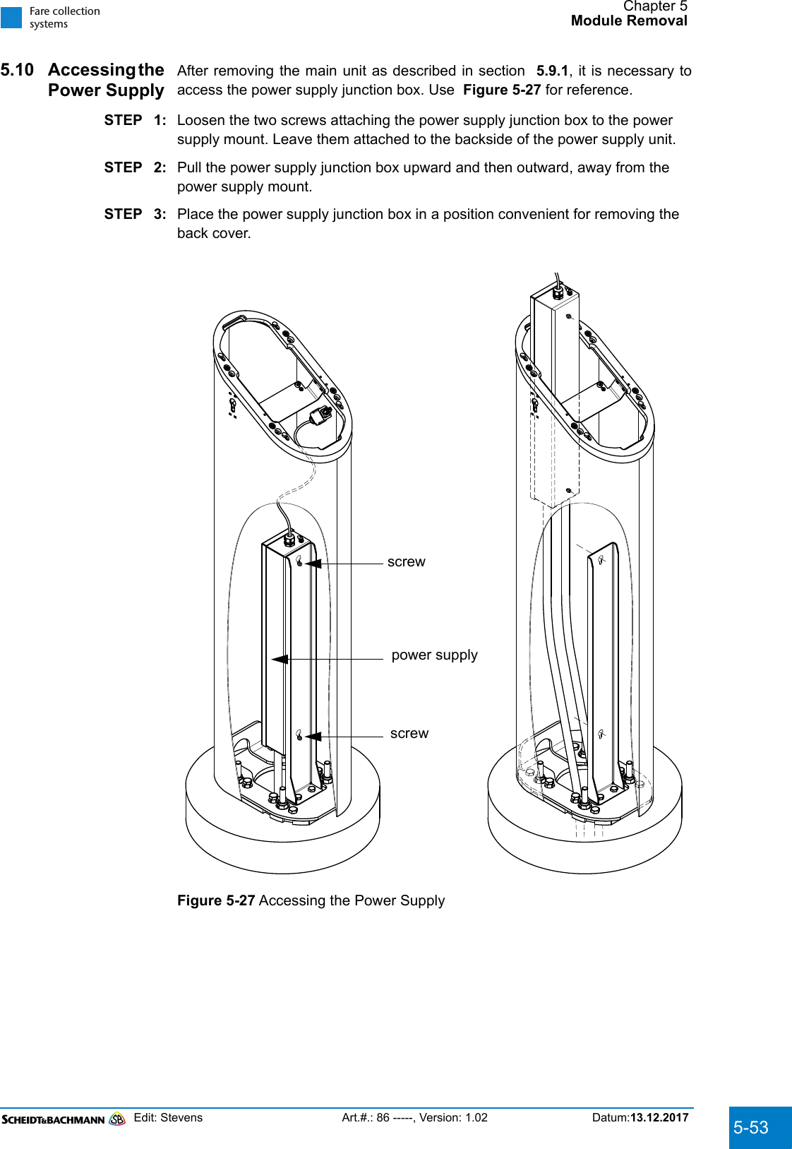
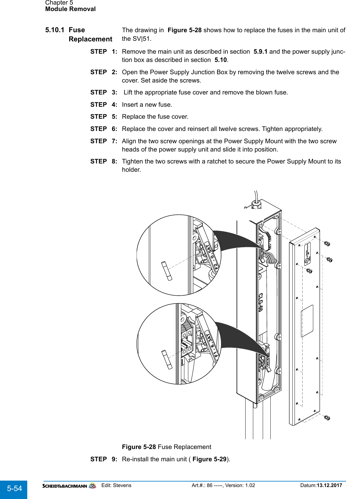
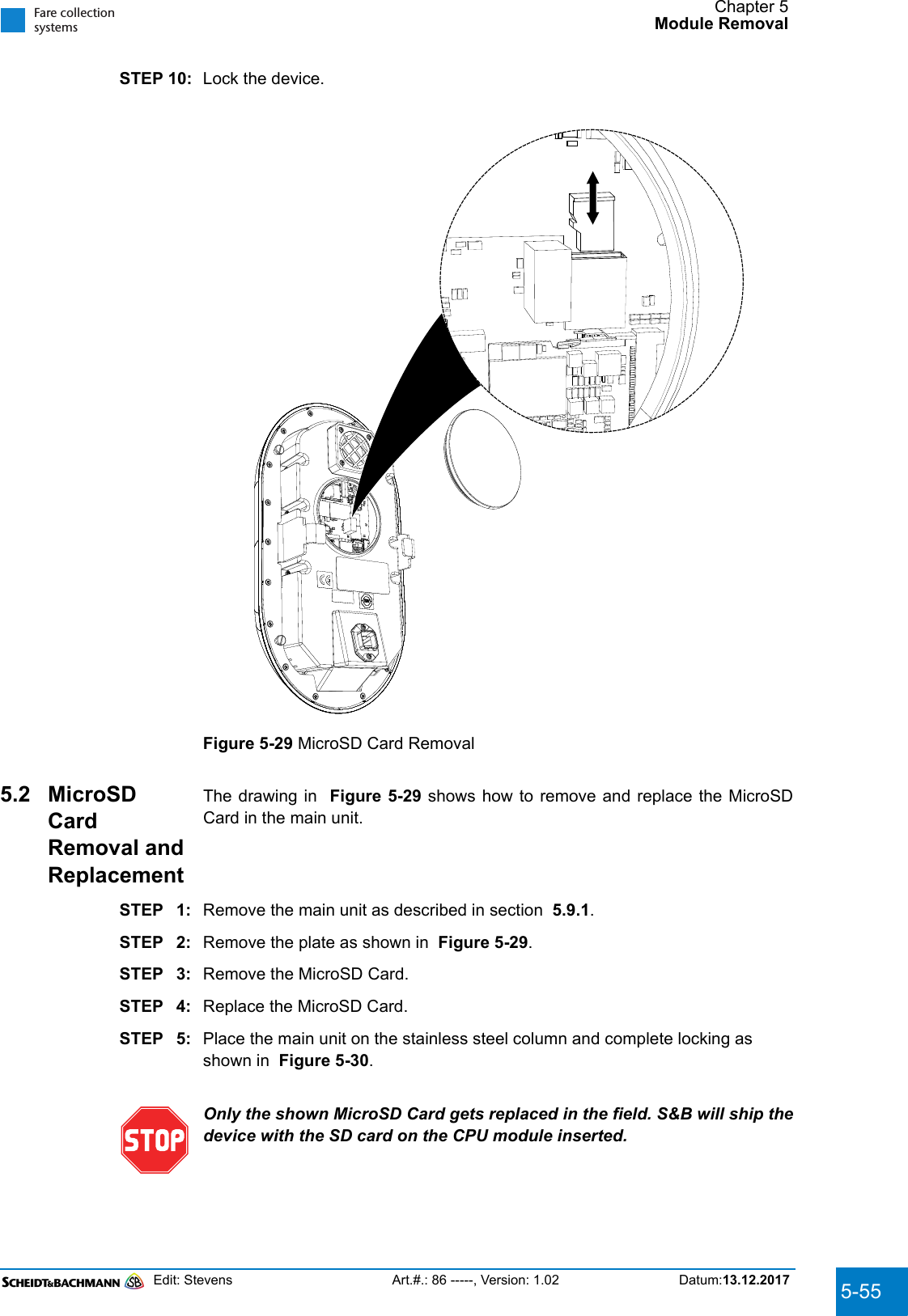
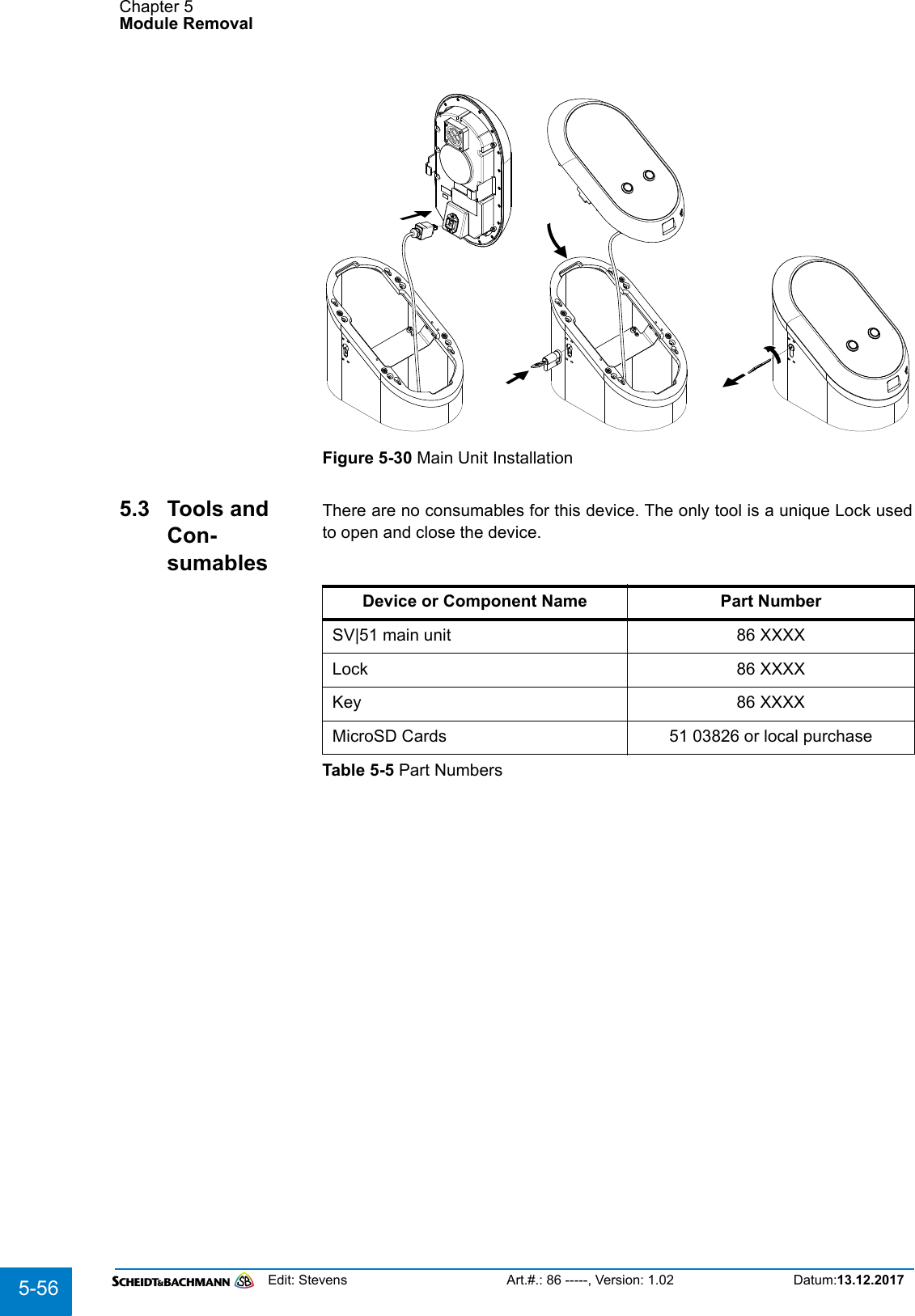
User Manual SV51
Contents
1.
User Manual SV51
2.
User Manual OV41
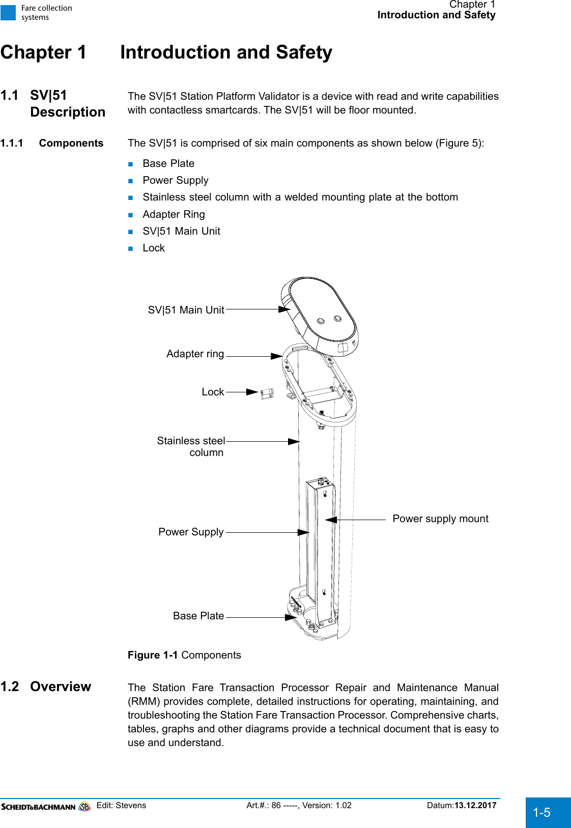
User Manual SV51
Navigation menu
Upload a User Manual
Namespaces
Wiki Guide
HTML
PDF
Info
Views
User Manual
Discussion / Help
Navigation

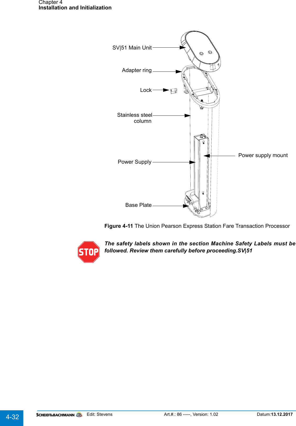
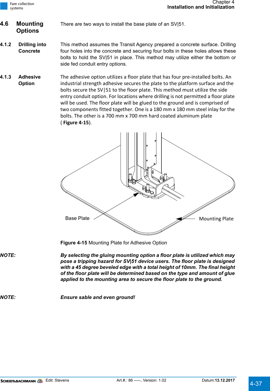
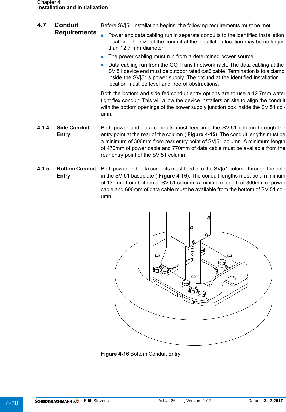
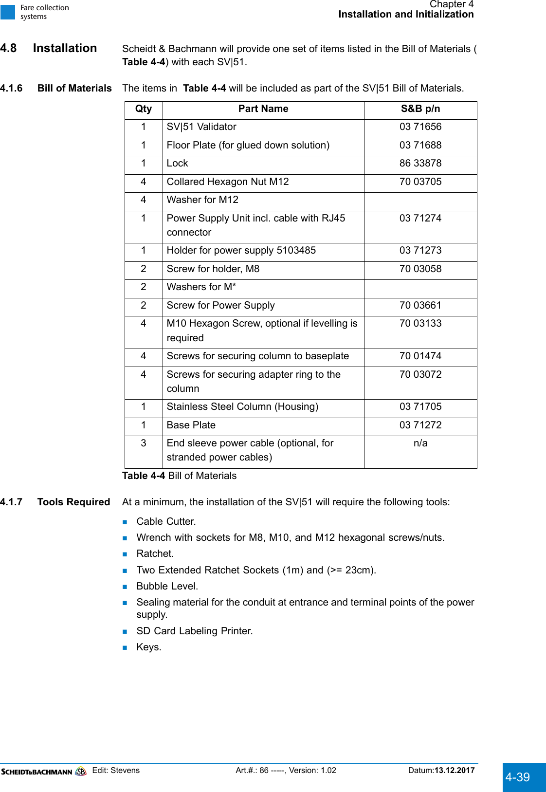
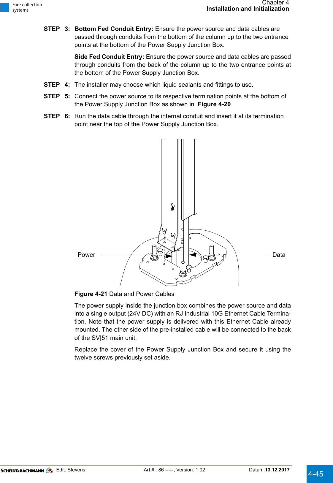
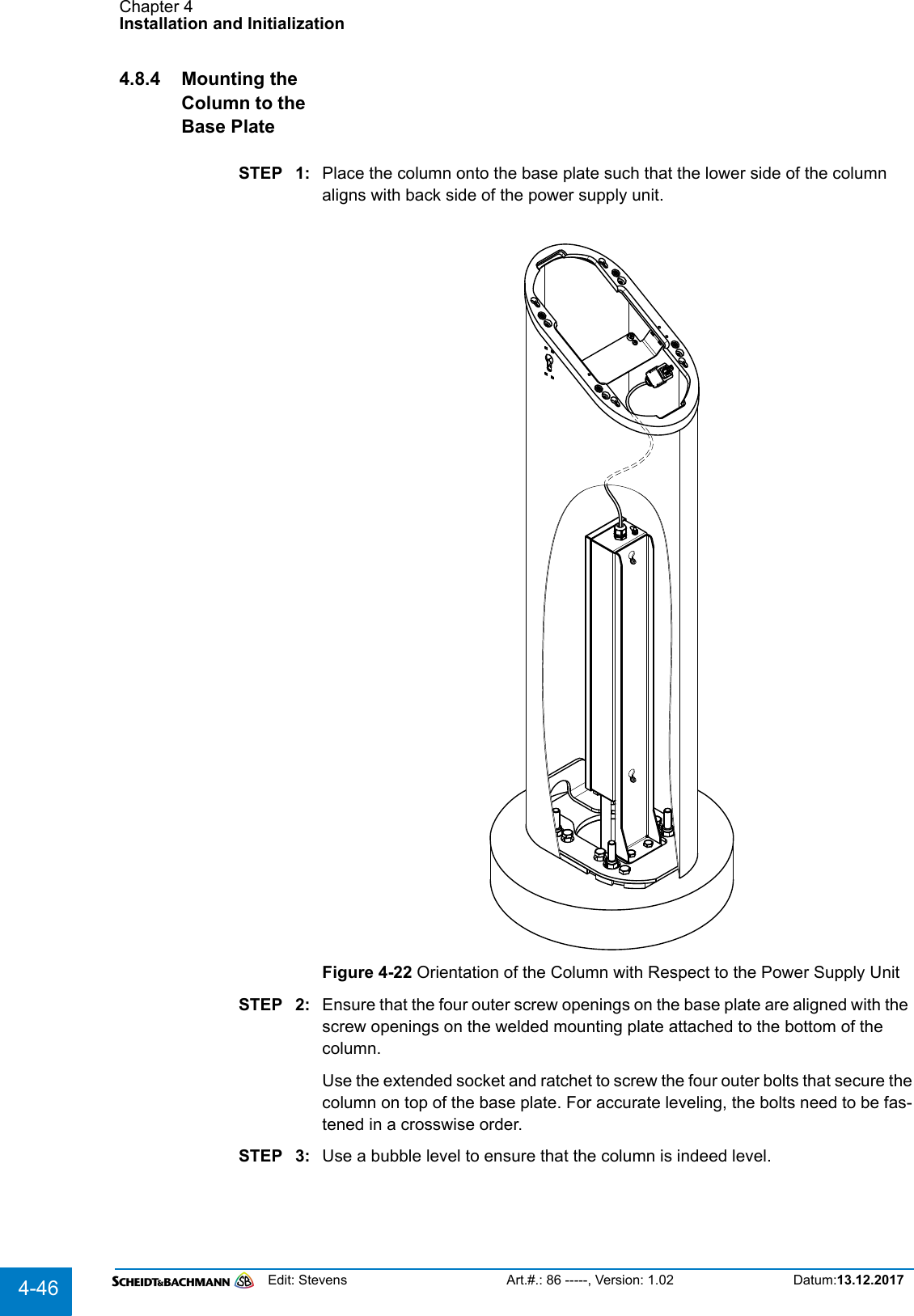
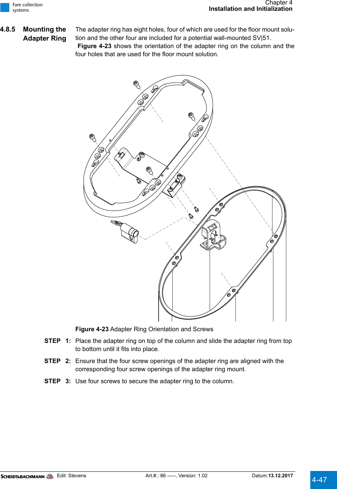
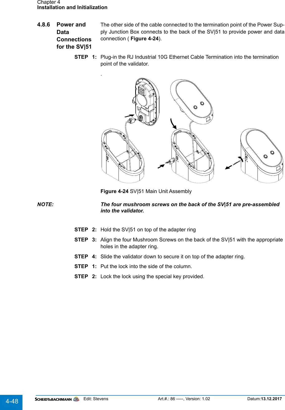
![Chapter 2GlossaryEdit: Stevens Art.#.: 86 -----, Version: 1.02 Datum:13.12.20172-16ANSI American National Standards InstituteApplication Server NT-based server which runs the Central Com-puter System Application processesAPTA American Public Transportation AssociationASCII American Standard Code for Information Inter-changeAudio Speaker A speaker that broadcasts messages in the lan-guage of choice with content similar to the mes-sage on the customer display.AWG American Wire Gauge, a measure of the cross section of a wire.BBank Account No. Bank account number of an employeeBank ID No. Bank identification number of an employeeBarcode A barcode is used to encrypt data into a series of vertical bars (universal product code [UPC]). It identifies various modules within an AFC device such as a ticket roll.Barcode Scanner The Barcode Scanner is a handheld scanner used to read barcodes (e.g. on replacement components).Battery Pack The Battery Pack module supplies 39 VDC if AFC machine main power is lost.Bitmap Bit-oriented graphicsBlower Also referred to as a “fan,” the blower cools the Central Processing Unit (CPU) in the ECU.Boot Loading of the operating system into the RAMByte 1 Byte = 8 BitCCAD/AVL Computer Aided Dispatch/Automatic Vehicle LocatorCard A credit, debit, stored value, or “smart” cardCard Reader See “Credit Card Reader”.CCS See “Central Computer System”.Central Computer System (CCS)Centralized company file server that collects and distributes operating and system fare col-lection data. The CCS serves all AFC system connected machines and devices.Command Instruction to initiate a special transaction](https://usermanual.wiki/Scheidt-and-Bachmann/NVP.User-Manual-SV51/User-Guide-3715281-Page-16.png)
![Chapter 2GlossaryEdit: Stevens Art.#.: 86 -----, Version: 1.02 Datum:13.12.20172-22NNEMA National Electrical Manufacturers AssociationNetwork Interface Card The Network Interface Card (NIC), installed in the ECU, provides an Ethernet-based commu-nications interface between an AFC machine and the Local Area Network (LAN).NIC Network Interface Card. Adapter for LANNoise Extraneous or interfering signals present on a system caused by undesirable voltages or cur-rents.NWC Abbreviation for Network ControllerOOccupational Safety and Health Administration (OSHA)The United States Government regulatory and oversight agency responsible for safety in the workplace.ODBC Open Data Base ConnectivityOEM Original Equipment ManufacturerOersted [Oe] 1 Oersted = 2.021268 Ampere per inchOnline/Offline If the TSM is connected to the Network, the net-work state of the TSM is online, if the TSM is disconnected, the state is offline.Oracle Manufacturer of database software.OSHA See “Occupational Safety and Health Adminis-tration”.PPacket A unit of data routed between an origin and a destination on any packet switching network. These “chunks” of data are an efficient size for routing.Pass A magnetically encoded document that pro-vides access to designated portions of the sys-tem for a specified time period.Password Every user has his own individual, classified password that provides access to equipment.Path The path describes the location of a data file.PC Personal Computer – a mass-market class of computer.PCB Printed Circuit Board](https://usermanual.wiki/Scheidt-and-Bachmann/NVP.User-Manual-SV51/User-Guide-3715281-Page-22.png)