Scheidt and Bachmann NVP Ticket-Vaildation device User Manual
Scheidt & Bachmann GmbH Ticket-Vaildation device
UserManual.wiki
>
Scheidt and Bachmann
>
NVP User Manual
>
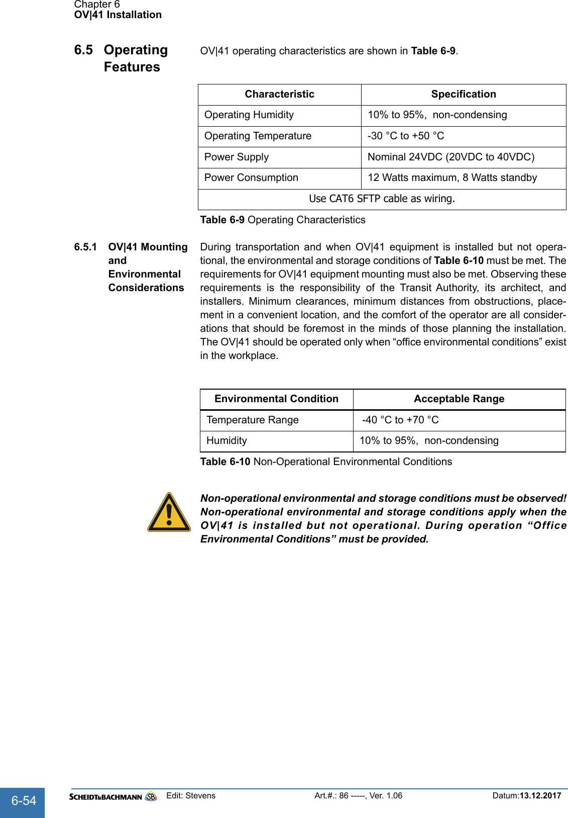
User Manual OV41
Contents
1.
User Manual SV51
2.
User Manual OV41
User Manual OV41
Navigation menu
Upload a User Manual
Namespaces
Wiki Guide
HTML
PDF
Info
Views
User Manual
Discussion / Help
Navigation
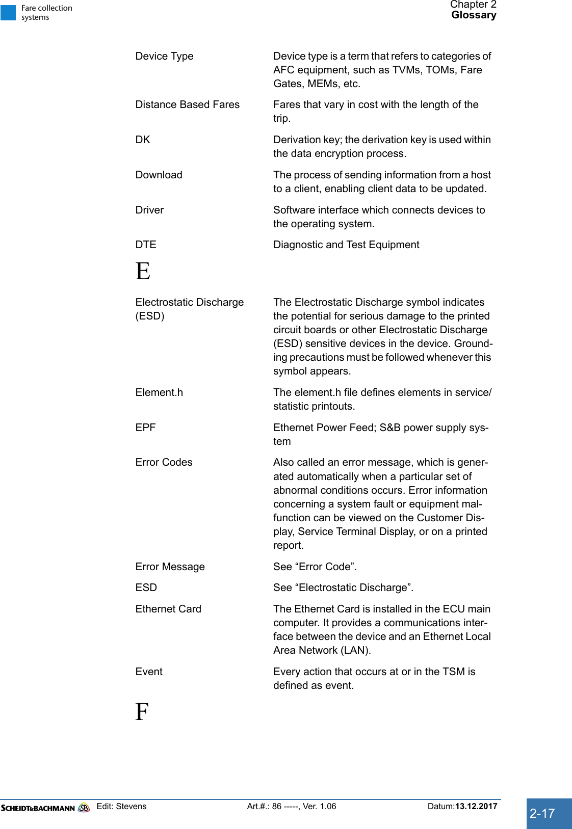
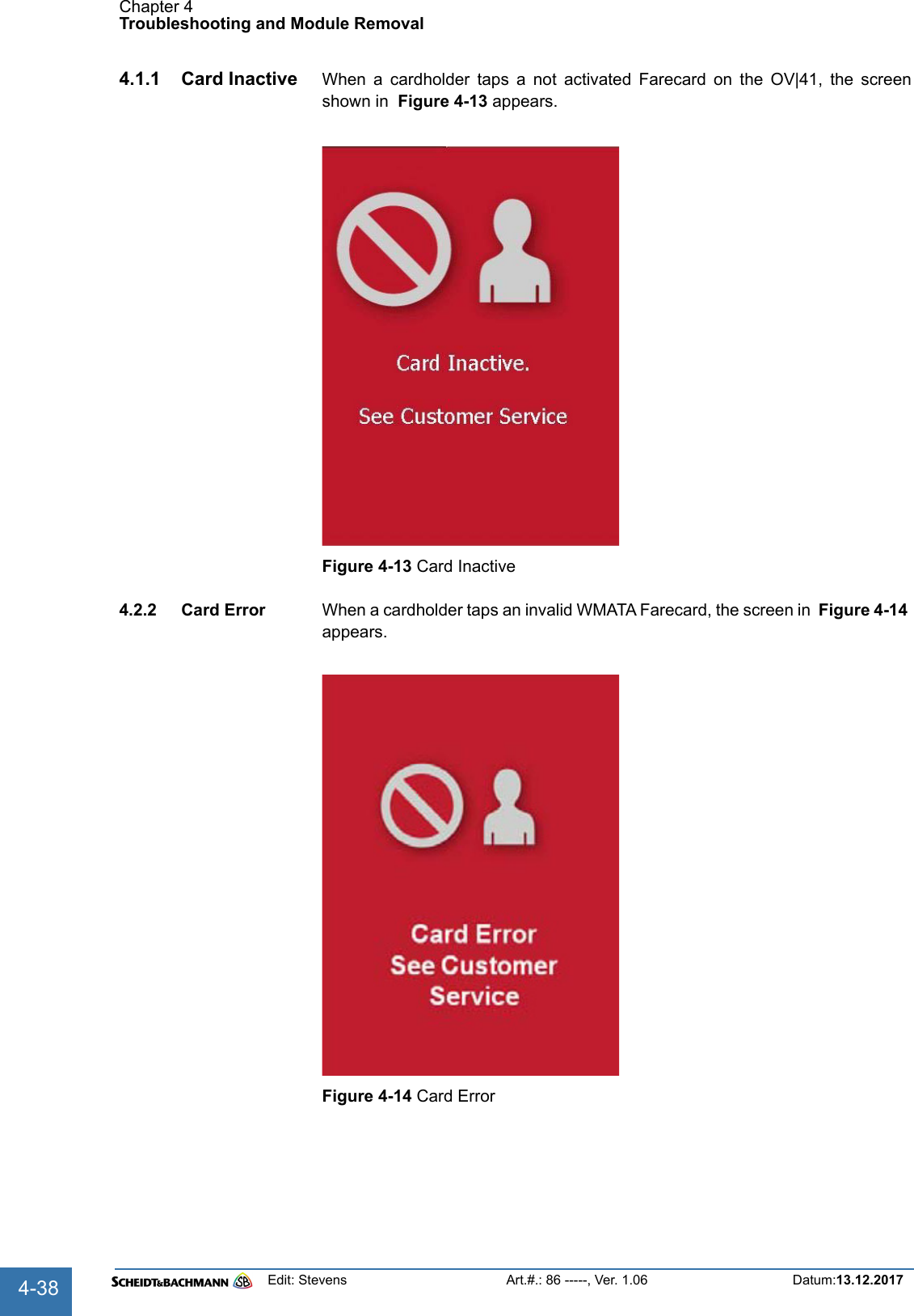
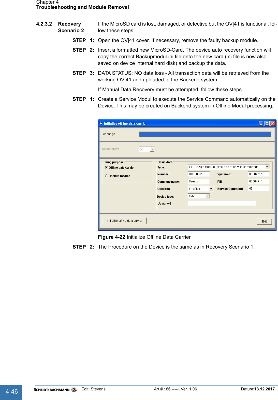
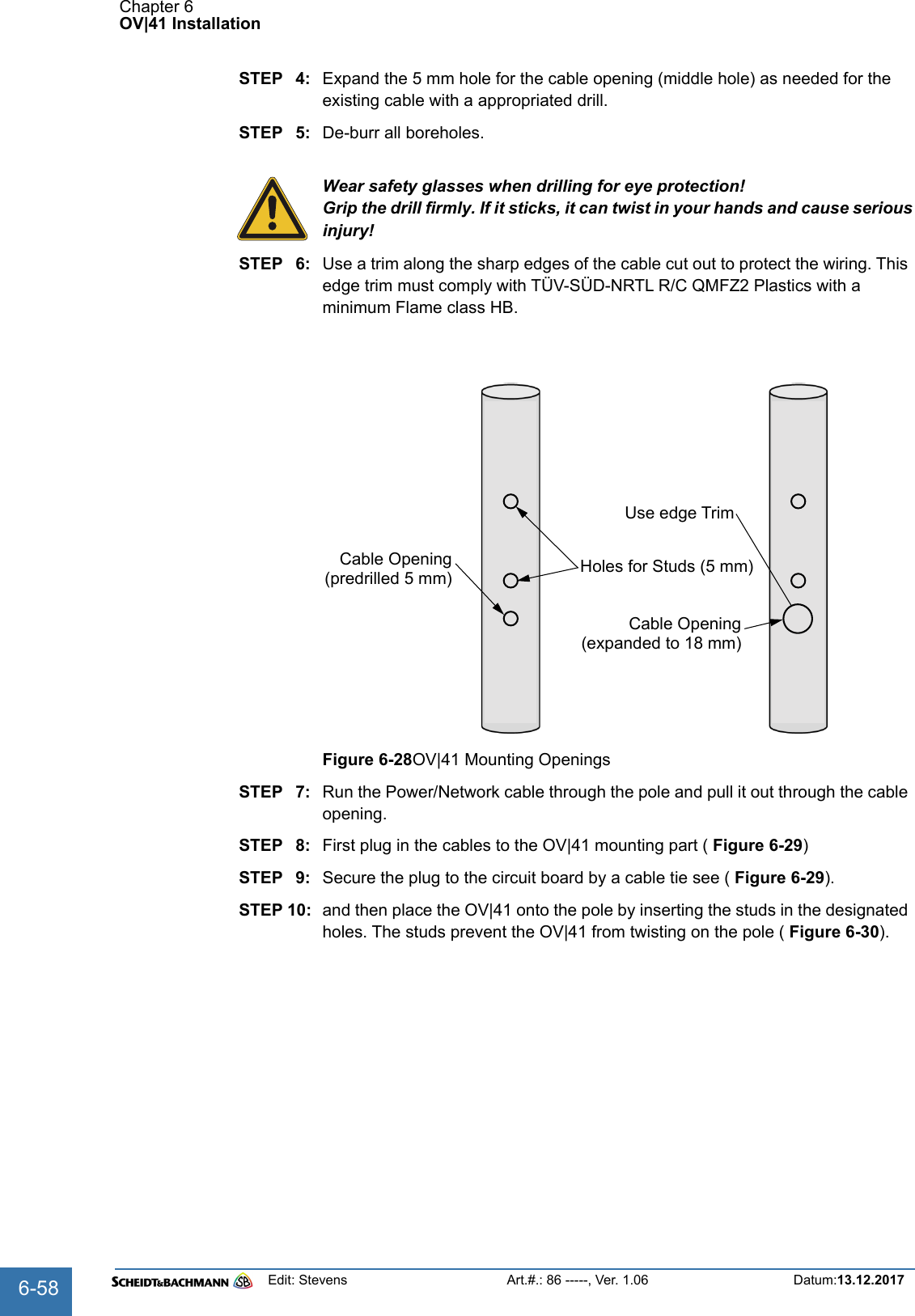
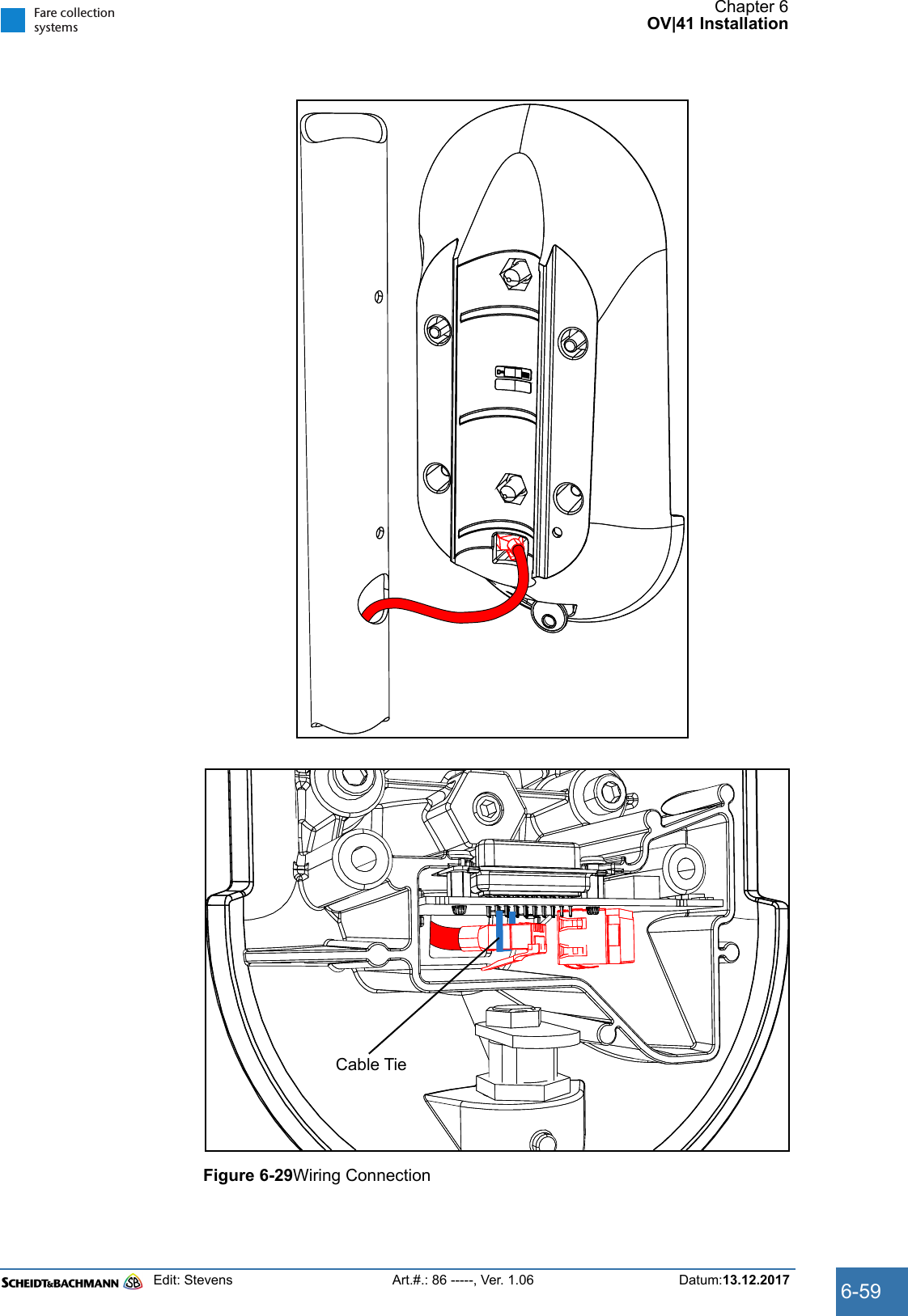
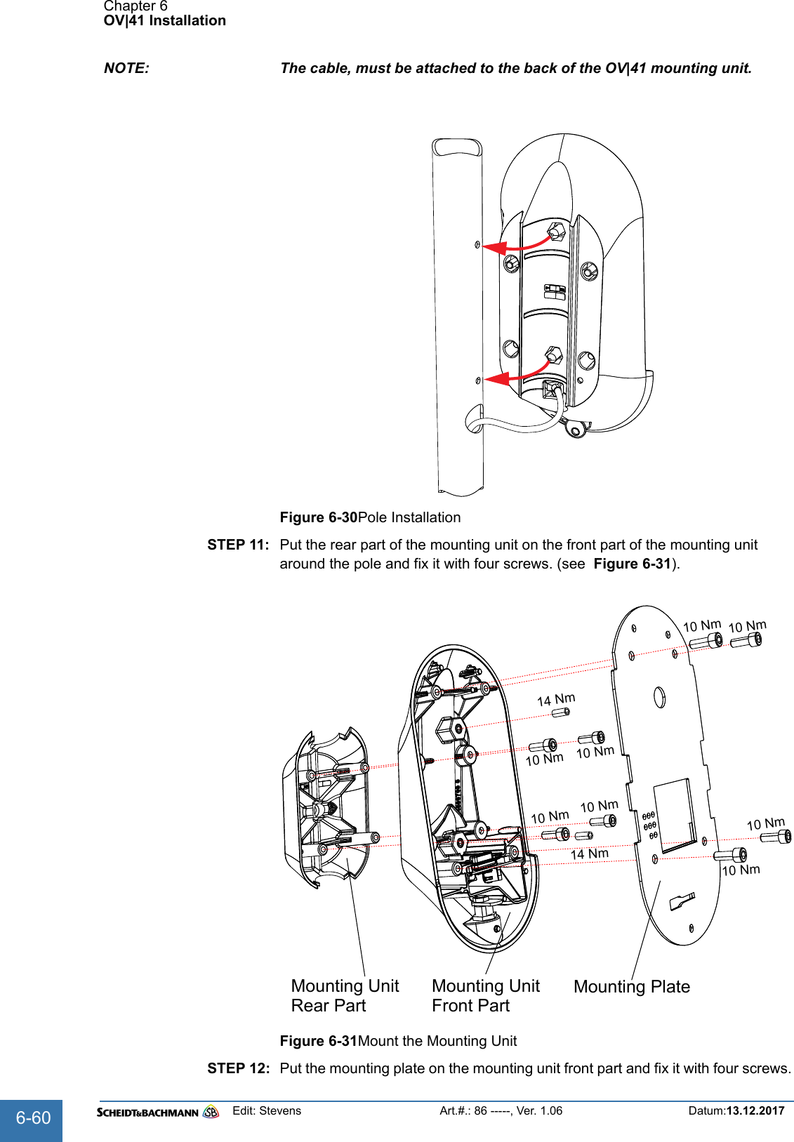
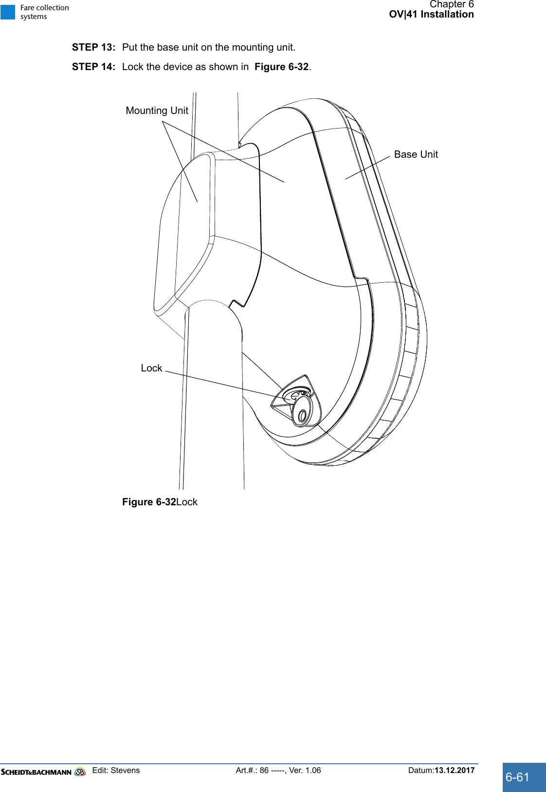
![Chapter 2GlossaryEdit: Stevens Art.#.: 86 -----, Ver. 1.06 Datum:13.12.20172-16Barcode A barcode is used to encrypt data into a series of vertical bars (universal product code [UPC]). It identifies various modules within an AFC device such as a ticket roll.Barcode Scanner The Barcode Scanner is a handheld scanner used to read barcodes (e.g. on replacement components).Bitmap Bit-oriented graphicsBlower Also referred to as a “fan,” the blower cools the Central Processing Unit (CPU) in the ECU.Boot Loading of the operating system into the RAMByte 1 Byte = 8 BitCCard A credit, debit, stored value, or “smart” cardCDCS See “Central Data Collection and Information System”.Central Data Collection System (CDCS)Centralized company file server that collects and distributes operating and system fare col-lection data. The CDCS serves all connected machines and devices.Command Instruction to initiate a special transactionCommand Codes See “Service Command”.CPU Central Processing UnitCRC Cyclic Redundancy Check. Check sum of the content of the file.Customer Display The Customer Display is a part of the user interface. In some devices, it may include a touch screen.Customer Specific Value A data field in which the customer is able to store individualized information.DDatabase A database is an accumulation of individual pieces of information that are related to each other.Database Server The Database Server is the CDCS hardware and software system on which the database is located.DC Direct CurrentDCM Data Control Module; a flash card used to update equipment in the field.](https://usermanual.wiki/Scheidt-and-Bachmann/NVP.User-Manual-OV41/User-Guide-3715288-Page-16.png)
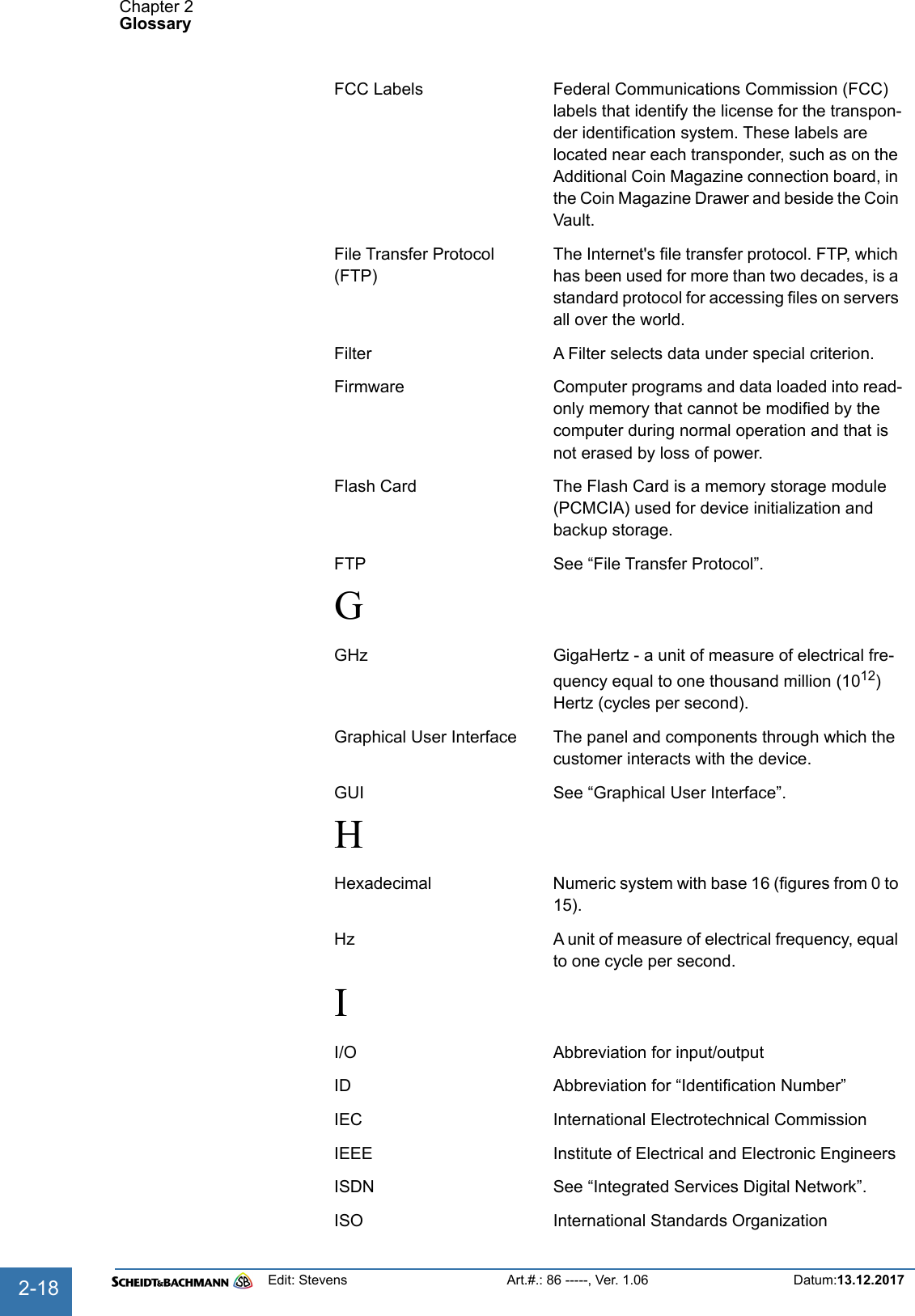
![Chapter 2GlossaryEdit: Stevens Art.#.: 86 -----, Ver. 1.06 Datum:13.12.20172-20mAh An mAh is a milliampere-hour. It is one thou-sandth of an ampere-hour and is commonly used as a measure of charge in batteries. An ampere-hour is the amount of energy charge in a battery that will allow one ampere of current to flow for one hour. The HCR battery is rated at 1200 mAh.Main Circuit Breaker The Main Circuit Breaker, which is located in the Power Connection Box, protects the system against high current overload.Main Module Main Application which controls the Central Server Application.Maintenance The action performed to prevent equipment performance degradation or failure (preventive maintenance) or restore the device to an in-ser-vice condition following a failure (corrective maintenance).MB Megabyte – one million bytes, where one byte equals 8 bits.Mbps Megabits per second – one million bits per sec-ondMDT Abbreviation for Mobile Data Transporter.MSHA Mine Safety and Health AdministrationMultimedia Multimedia includes texts, pictures and audio data.NNEMA National Electrical Manufacturers AssociationNoise Extraneous or interfering signals present on a system caused by undesirable voltages or cur-rents.NRTL National Registered Test LaboratoryNWC Abbreviation for Network ControllerOOccupational Safety and Health Administration (OSHA)The United States Government regulatory and oversight agency responsible for safety in the workplace.ODBC Open Data Base ConnectivityOEM Original Equipment ManufacturerOersted [Oe] 1 Oersted = 2.021268 Ampere per inch](https://usermanual.wiki/Scheidt-and-Bachmann/NVP.User-Manual-OV41/User-Guide-3715288-Page-20.png)
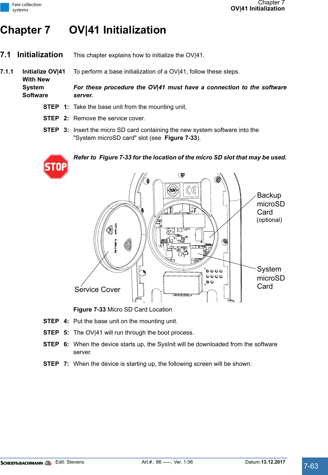
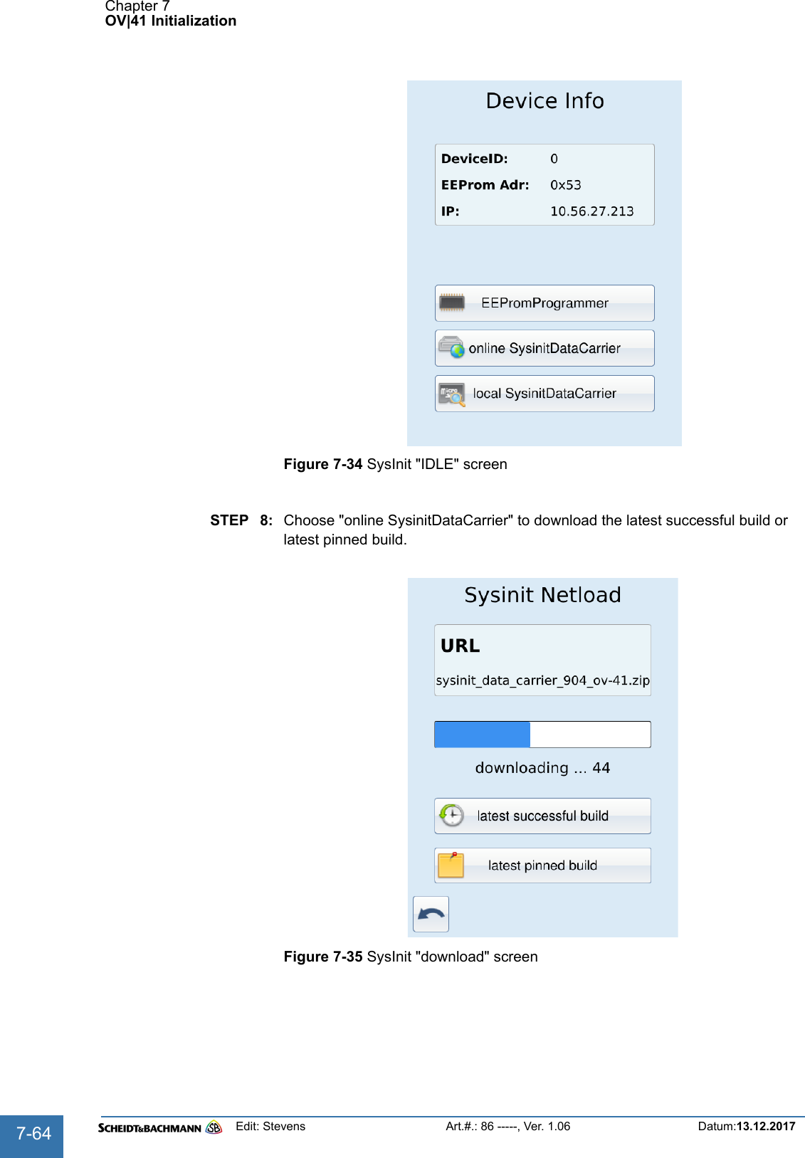
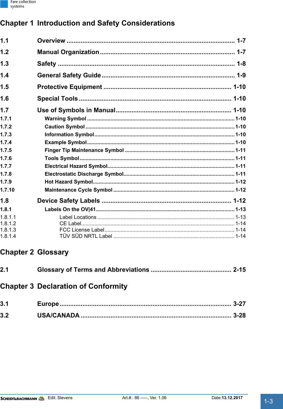
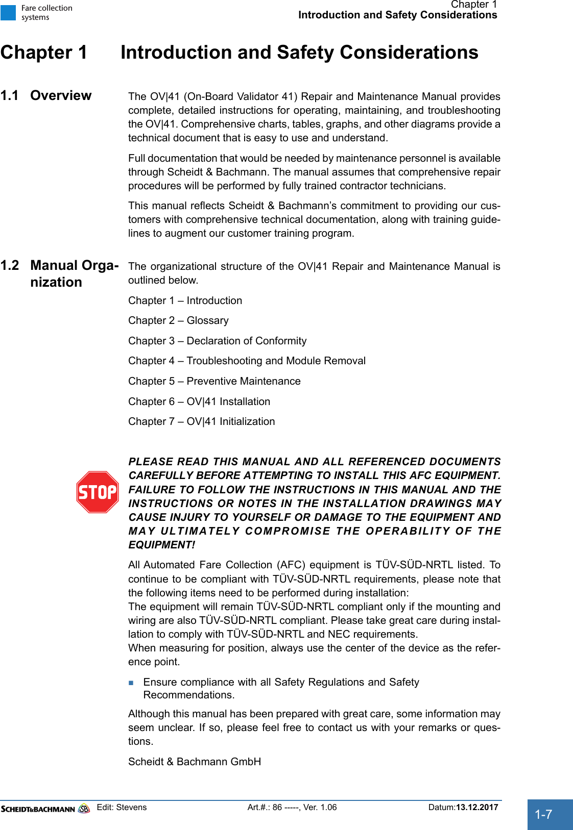
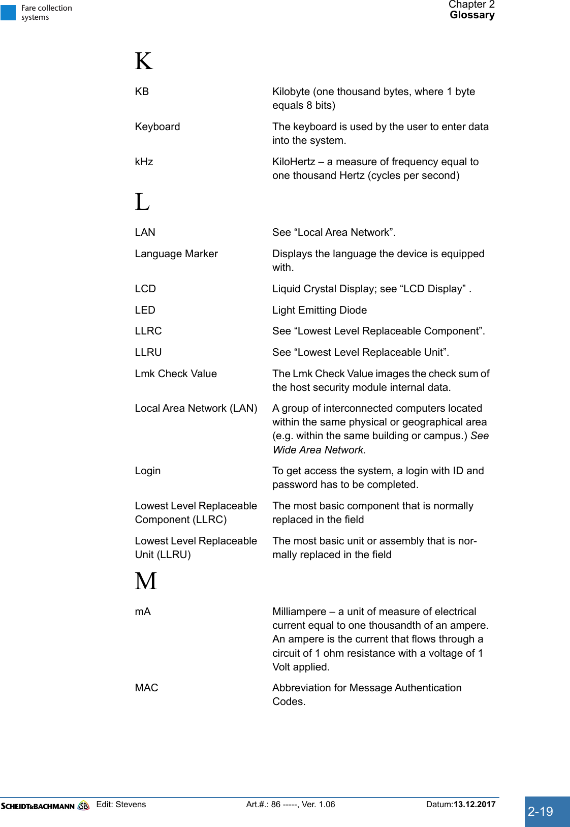
![Chapter 7OV|41 InitializationEdit: Stevens Art.#.: 86 -----, Ver. 1.06 Datum:13.12.2017 7-65Fare collectionsystemsSTEP 9: When the SysInit Data Carrier was successfully downloaded, press "run sysinit".Figure 7-36 SysInit "run SysInit" screenSTEP 10: After a minute the device will reboot. Now you see the processes starting:STEP 11: After successful starting of all processes, the customer application will start and the IDLE screen will be displayed.sbuser@Trizeps7:~$ psiinfo -l PSI - Process ListProcess-ID Status (Name)0x00000020 running (PSI Timer Process)0x00000021 running (Config Process)0x00000023 running (Powerfail Process)0x00000027 running (Tcp32 Process)0x00000031 running (Crypto Process)0x00001081 running (Version Control [135_1551])0x00001088 running (Transaction Recorder [177_1349])0x00001100 running (DeviceControl [169_1481])0x00001413 running (Event-/Status-Handler)0x00002100 running (Service Process [127_1352])0x00003405 running (Production Process)0x0000340C running (Smart Card Process Version 16.9.26,o,r)0x00003800 running (Payment)0x00003806 running (LogicalIO [211_1673:16/11/16_0949])0x00003C50 running (Filetransfer)0x00003C51 running (OnlineControl)0x00004C01 running (PxUSB S&B Smartcard Reader)0xFFFFFFFC running0xFFFFFFFE running (Rousnp Process)](https://usermanual.wiki/Scheidt-and-Bachmann/NVP.User-Manual-OV41/User-Guide-3715288-Page-65.png)