Scheidt and Bachmann NVP Ticket-Vaildation device User Manual
Scheidt & Bachmann GmbH Ticket-Vaildation device
Contents
- 1. User Manual SV51
- 2. User Manual OV41
User Manual OV41
Edit: Stevens Art.#.: 86 -----, Ver. 1.06 Date:13.12.2017
Fare collection
systems
State: December 2017
Customer Documentation
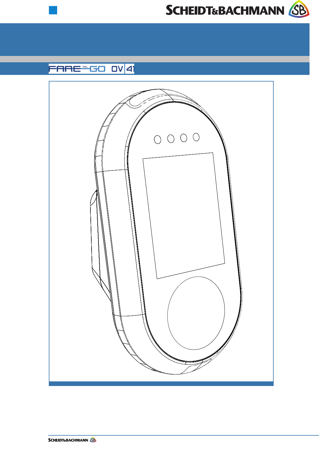
FareGo VAL OV|41

Edit: Stevens Art.#.: 86 -----, Ver. 1.06 Date:13.12.2017
This manual, including all of its component parts, is copyright protected. Scheidt & Bachmann GmbH
reserves all rights to its contents. Any use not expressly approved by copyright law is subject to prior
approval by Scheidt & Bachmann GmbH. This applies particularly to copying, processing, translations and
microfilming, as well as to storage and data processing in any electronic systems.
All contents of this manual shall be treated confidentially and shall not be transferred to any third party, either
for their own commercial use or for any other client.
Since all information and facts are subject to technical changes, any liability for the data contained is hereby
disclaimed. Modifications of technical details, in terms of information and illustrations are reserved. Make
sure to follow the updating index. Scheidt & Bachmann GmbH cannot be held responsible for direct damage
and/or possible consequential damage due to misuse by the customer or by third parties, unless the Product
Liability Act (ProdHaftG) is concerned. In no event shall Scheidt & Bachmann GmbH be liable for any dam-
age out of or in connection with the provision of the manual.
© 2017 Scheidt & Bachmann GmbH, Fare collection system (FCS)
Breite Straße 132 41238 Mönchengladbach
www.scheidt-bachmann.com
Subject to change.
History
Version Date Change Edit
1.00 01.12.2016 Start Version Stevens
1.01 31.03.2017 Reduced the contents of the manual to
OV|41 relevant topics
Stevens
1.02 03.04.2017 Changes made according to specifications
from the design department
Stevens
1.03 05.07.2017 Information on radio frequencies added Stevens
1.04 21.08.2017 Changes made according to specifications
from the design department (C.Gerspacher)
Stevens
1.05 15.09.2017 Changes made according to specifications
from the design department (N.Huendgen.)
Stevens
1.06 13.12.2017 Changes made according to specifications
from the design department
(N. Huendgen. and I. Izler)
Stevens
Table 1-1

Edit: Stevens Art.#.: 86 -----, Ver. 1.06 Date:13.12.2017 1-3
Fare collection
systems
Chapter 1 Introduction and Safety Considerations
1.1 Overview ................................................................................................ 1-7
1.2 Manual Organization............................................................................. 1-7
1.3 Safety ..................................................................................................... 1-8
1.4 General Safety Guide............................................................................ 1-9
1.5 Protective Equipment ......................................................................... 1-10
1.6 Special Tools ....................................................................................... 1-10
1.7 Use of Symbols in Manual.................................................................. 1-10
1.7.1 Warning Symbol .....................................................................................................1-10
1.7.2 Caution Symbol ......................................................................................................1-10
1.7.3 Information Symbol................................................................................................ 1-10
1.7.4 Example Symbol..................................................................................................... 1-10
1.7.5 Finger Tip Maintenance Symbol ...........................................................................1-11
1.7.6 Tools Symbol..........................................................................................................1-11
1.7.7 Electrical Hazard Symbol....................................................................................... 1-11
1.7.8 Electrostatic Discharge Symbol............................................................................ 1-11
1.7.9 Hot Hazard Symbol................................................................................................. 1-12
1.7.10 Maintenance Cycle Symbol ...................................................................................1-12
1.8 Device Safety Labels .......................................................................... 1-12
1.8.1 Labels On the OV|41............................................................................................... 1-13
1.8.1.1 Label Locations ..............................................................................................1-13
1.8.1.2 CE Label......................................................................................................... 1-14
1.8.1.3 FCC License Label......................................................................................... 1-14
1.8.1.4 TÜV SÜD NRTL Label ................................................................................... 1-14
Chapter 2 Glossary
2.1 Glossary of Terms and Abbreviations .............................................. 2-15
Chapter 3 Declaration of Conformity
3.1 Europe.................................................................................................. 3-27
3.2 USA/CANADA ...................................................................................... 3-28

Edit: Stevens Art.#.: 86 -----, Ver. 1.06 Date:13.12.2017
1-4
Chapter 4 Troubleshooting and Module Removal
4.1 Troubleshooting Overview..................................................................4-31
4.1.1 Out of Service ......................................................................................................... 4-31
4.2 Error Identification...............................................................................4-32
4.2.1 Blocked Card .......................................................................................................... 4-37
4.2.2 Card Error ............................................................................................................... 4-38
4.2.3 Recovery Scenarios ............................................................................................... 4-45
4.2.3.1 Recovery Scenario 1...................................................................................... 4-45
4.2.3.2 Recovery Scenario 2...................................................................................... 4-46
4.3 Verifying Software Versions ...............................................................4-47
4.4 Tools and Consumables .....................................................................4-47
Chapter 5 Preventive Maintenance
5.1 General Maintenance and Cleaning ...................................................5-49
5.2 Preventive Maintenance Schedule Summary....................................5-50
5.3 Materials and Replacement Parts.......................................................5-50
Chapter 6 OV|41 Installation
6.1 Overview ...............................................................................................6-51
6.2 Hardware...............................................................................................6-51
6.3 Dimension and Weight ........................................................................6-51
6.4 Power Requirements ...........................................................................6-51
6.5 Operating Features ..............................................................................6-54
6.5.1 OV|41 Mounting and Environmental Considerations ......................................... 6-54
6.6 Installation Requirements ...................................................................6-55
6.6.1 Materials.................................................................................................................. 6-55
6.6.2 Standard Tools ....................................................................................................... 6-55
6.6.3 Special Tools .......................................................................................................... 6-55
6.7 Needs and Requirements for OV|41 Installation...............................6-55
6.8 Installation ............................................................................................6-56
6.9 Post-Installation Checklist ..................................................................6-62
6.10 Disassembly and Removal..................................................................6-62

Edit: Stevens Art.#.: 86 -----, Ver. 1.06 Date:13.12.2017 1-5
Fare collection
systems
Chapter 7 OV|41 Initialization
7.1 Initialization ......................................................................................... 7-63
7.1.1 Initialize OV|41 With New System Software.........................................................7-63

Edit: Stevens Art.#.: 86 -----, Ver. 1.06 Date:13.12.2017
1-6

Chapter 1
Introduction and Safety Considerations
Edit: Stevens Art.#.: 86 -----, Ver. 1.06 Datum:13.12.2017 1-7
Fare collection
systems
Chapter 1 Introduction and Safety Considerations
1.1 Overview The OV|41 (On-Board Validator 41) Repair and Maintenance Manual provides
complete, detailed instructions for operating, maintaining, and troubleshooting
the OV|41. Comprehensive charts, tables, graphs, and other diagrams provide a
technical document that is easy to use and understand.
Full documentation that would be needed by maintenance personnel is available
through Scheidt & Bachmann. The manual assumes that comprehensive repair
procedures will be performed by fully trained contractor technicians.
This manual reflects Scheidt & Bachmann’s commitment to providing our cus-
tomers with comprehensive technical documentation, along with training guide-
lines to augment our customer training program.
1.2 Manual Orga-
nization
The organizational structure of the OV|41 Repair and Maintenance Manual is
outlined below.
Chapter 1 – Introduction
Chapter 2 – Glossary
Chapter 3 – Declaration of Conformity
Chapter 4 – Troubleshooting and Module Removal
Chapter 5 – Preventive Maintenance
Chapter 6 – OV|41 Installation
Chapter 7 – OV|41 Initialization
PLEASE READ THIS MANUAL AND ALL REFERENCED DOCUMENTS
CAREFULLY BEFORE ATTEMPTING TO INSTALL THIS AFC EQUIPMENT.
FAILURE TO FOLLOW THE INSTRUCTIONS IN THIS MANUAL AND THE
INSTRUCTIONS OR NOTES IN THE INSTALLATION DRAWINGS MAY
CAUSE INJURY TO YOURSELF OR DAMAGE TO THE EQUIPMENT AND
MAY ULTIMATELY COMPROMISE THE OPERABILITY OF THE
EQUIPMENT!
All Automated Fare Collection (AFC) equipment is TÜV-SÜD-NRTL listed. To
continue to be compliant with TÜV-SÜD-NRTL requirements, please note that
the following items need to be performed during installation:
The equipment will remain TÜV-SÜD-NRTL compliant only if the mounting and
wiring are also TÜV-SÜD-NRTL compliant. Please take great care during instal-
lation to comply with TÜV-SÜD-NRTL and NEC requirements.
When measuring for position, always use the center of the device as the refer-
ence point.
Ensure compliance with all Safety Regulations and Safety
Recommendations.
Although this manual has been prepared with great care, some information may
seem unclear. If so, please feel free to contact us with your remarks or ques-
tions.
Scheidt & Bachmann GmbH
Chapter 1
Introduction and Safety Considerations
Edit: Stevens Art.#.: 86 -----, Ver. 1.06 Datum:13.12.2017
1-8
DISCLAIMER
Scheidt & Bachmann GmbH IS NOT LIABLE FOR INJURIES TO ANY
PERSON OR DAMAGE TO THE EQUIPMENT RESULTING FROM FAILURE
TO COMPLY WITH THE MANUFACTURER’S INSTRUCTIONS OR
DOCUMENTATION. THIS DISCLAIMER INCLUDES ALL THIRD PARTY
DOCUMENTATION PREPARED BY OEMS AND PROVIDED AS A
COURTESY BY Scheidt & Bachmann GmbH. TO ITS CUSTOMERS.
1.3 Safety This section describes safety requirements for technicians who perform mainte-
nance or repair procedures for all AFC Systems. Information provided in this
chapter also includes a description of safety warnings and precautions.
PLEASE READ THIS MANUAL AND ALL REFERENCED DOCUMENTS
CAREFULLY BEFORE ATTEMPTING TO WORK WITH THIS EQUIPMENT.
FAILURE TO FOLLOW THE INSTRUCTIONS IN THIS ENTIRE MANUAL
MAY CAUSE INJURY TO YOURSELF OR DAMAGE TO THE EQUIPMENT
AND MAY ULTIMATELY COMPROMISE THE OPERABILITY OF THE
EQUIPMENT!
DISCLAIMER
Scheidt & Bachmann GmbH IS NOT LIABLE FOR INJURIES TO ANY
PERSON OR DAMAGE TO THE EQUIPMENT RESULTING FROM FAILURE
TO COMPLY WITH THE MANUFACTURER’S INSTRUCTIONS OR
DOCUMENTATION. THIS DISCLAIMER INCLUDES ALL THIRD PARTY
DOCUMENTATION PREPARED BY OEMS AND PROVIDED AS A
COURTESY BY Scheidt & Bachmann GmbH TO ITS CUSTOMERS.
FAILURE TO FOLLOW MANUFACTURER’S INSTRUCTIONS MAY
INVALIDATE ANY OR ALL WARRANTIES, EXPRESS OR IMPLIED.
NOTE: NOT ALL OF THESE WARNING LABELS OR HAZARDS MAY EXIST IN ALL
AFC DEVICES. ONLY THOSE LABELS THAT APPLY TO THE OV|41, AND
ARE REQUIRED TO MEET TÜV-SÜD-NRTL CERTIFICATION REQUIRE-
MENTS, WILL BE FOUND IN THE OV|41. BE CAUTIOUS AND OBSERVANT,
AND LOOK FOR SUCH WARNING LABELS AND POTENTIAL HAZARDS.
ANY TECHNICIAN OR PERSON ACCESSING THE INTERIOR OF ANY AFC
DEVICE SHOULD USE COMMON SENSE AND EXERCISE EXTREME CAU-
TION.
Safety Features
Safety engineering is an integral part of Scheidt & Bachmann’s designs. Mainte-
nance technicians must perform maintenance and repair in accordance with
industry safety standards including MSHA, OSHA, and other Federal, State, and
Local codes and regulations.
Close attention to proper safety precautions is of the utmost importance. Com-
ponents should be installed, maintained, and repaired only by trained, qualified
personnel using reasonable care. Improper installation, maintenance, or repair
procedures may damage the device or cause serious personal injury or death.
The following pages provide detailed information on safety precautions that
must be observed when working on AFC Systems. This information should be
carefully read and thoroughly understood before performing routine mainte-
nance or attempting to troubleshoot or repair the device.

Chapter 1
Introduction and Safety Considerations
Edit: Stevens Art.#.: 86 -----, Ver. 1.06 Datum:13.12.2017 1-9
Fare collection
systems
It is the responsibility of the maintenance agency to ensure that the safety
instructions in this manual are read, understood, and implemented by properly
trained maintenance and service technicians. All other persons who work with
the internal systems of any AFC systems should also be trained in safety.
1.4 General
Safety Guide
This chapter provides the technician with the safety information necessary to
avoid personal injury or equipment damage. Only qualified, trained technicians
using reasonable care should perform maintenance or repair. As with any
mechanical system, the AFC components can pose certain safety hazards. The
following guidelines must be followed when working on the mechanical systems
of any AFC Systems or Components.
Only competent, qualified technicians trained by Scheidt & Bachmann should
service this device.
Service technicians must read and understand all operating and service
instructions.
Turn electrical power off before opening any electrical enclosure.
Do not operate the device with the cover of any enclosure, or the guard or
covers over any mechanism, removed.
Due consideration should be given to any safety regulation applicable to the
particular location in which the device is operating.
Do not turn on power to the device when components are disconnected.
The device must not be used for any purpose other than that for which it was
designed and approved by Scheidt & Bachmann.
When servicing or repairing the device, all device control panels must be
tagged in compliance with OSHA Lockout/Tag out procedures to indicate that
the device should not be operated.
Chapter 1
Introduction and Safety Considerations
Edit: Stevens Art.#.: 86 -----, Ver. 1.06 Datum:13.12.2017
1-10
1.5 Protective
Equipment
The technician should use care when working with solvents and other cleaning
agents that may be abrasive or have a tendency to cause irritation to the skin or
eyes. Read all labels carefully and follow instructions for the use of gloves when
working with chemical fluids.
When using cleaning agents such as fluids or pressurized air, safety glasses
must be worn to prevent eye damage.
1.6 Special Tools There are no special tools required to ensure the safety of the service techni-
cian. However, ESD (Electrostatic Discharge: see paragraph 1.7.8) protection is
required for all procedures involving contact with electrostatic sensitive printed
circuit boards. The use of a standard ESD Safety Wrist Strap is required when
working with electrostatic sensitive printed circuit boards.
1.7 Use of
Symbols in
Manual
Symbols for cautions and warnings are used frequently throughout this manual.
Each symbol appears on the left side of the page with the associated text printed
to the right.
There are several different types of symbols that indicate varying levels of safety
hazards. Detailed information on each symbol is provide in this chapter.
It is vital that the technician understand and follow all safety warnings, cautions
and information guidelines when working on AFC Systems.
1.7.1 Warning
Symbol
The Warning Symbol indicates a potential for serious damage to the equipment
or serious injury to the maintenance or service technician. Extreme care should
be used when performing procedures that are preceded by this symbol.
This symbol indicates a WARNING. A detailed description of the particular
hazard will appear next to the symbol in bold, italic print.
1.7.2 Caution Symbol The Caution Symbol indicates a potential for damage to a particular part or func-
tion of the device. Reasonable care should be used when performing proce-
dures preceded by this symbol.
This symbol indicates a CAUTION. A detailed description of the particular
hazard will appear next to the symbol in bold, italic print.
1.7.3 Information
Symbol
The Information Symbol indicates special information that could be important for
protecting a particular part or function of the device. Reasonable care should be
used when performing procedures that are preceded by this symbol.
This symbol indicates that more INFORMATION follows. A detailed
description of the particular hazard will appear next to the symbol in bold,
italic print.
1.7.4 Example
Symbol
The Example Symbol precedes an example of a function. The text or illustration
explains one possible function. This explanation applies to all other functions of
the same kind.
Chapter 1
Introduction and Safety Considerations
Edit: Stevens Art.#.: 86 -----, Ver. 1.06 Datum:13.12.2017 1-11
Fare collection
systems
This symbol indicates that an EXAMPLE follows.
1.7.5 Finger Tip
Maintenance
Symbol
The Finger Tip Symbol indicates that no tools are required to perform the task
described. Reasonable care should be used when performing procedures that
are preceded by this symbol.
This symbol indicates a FINGER TIP MAINTENANCE action. A step-by-
step description of the task will appear next to the symbol in bold, italic
print.
1.7.6 Tools Symbol The Tools Symbol indicates that tools are required to perform the task
described. Reasonable care should be used when performing procedures that
are preceded by this symbol.
This symbol indicates a TOOL is required to perform the task described in
the text.
1.7.7 Electrical
Hazard Symbol
The Electrical Hazard Symbol indicates the potential for serious damage to the
device caused by electrical voltage surges or serious injury to the service tech-
nician caused by electrical shock. Extreme care should be used when perform-
ing procedures preceded by this symbol.
This symbol indicates possibility of ELECTRICAL HAZARD. A detailed
description of the particular hazard will appear next to the symbol in bold,
italic print.
1.7.8 Electrostatic
Discharge
Symbol
The Electrostatic Discharge Symbol indicates the potential for serious damage
to the printed circuit boards or other Electrostatic Discharge (ESD) sensitive
devices in the device. Extreme care should be used when performing proce-
dures preceded by this symbol. The technician should wear a grounding strap
and use the proper techniques associated with handling printed circuit boards or
other ESD sensitive devices.
This symbol indicates an ESD HAZARD. A detailed description of the
particular hazard will appear next to the symbol in bold, italic print.

Chapter 1
Introduction and Safety Considerations
Edit: Stevens Art.#.: 86 -----, Ver. 1.06 Datum:13.12.2017
1-12
1.7.9 Hot Hazard
Symbol
The Hot Hazard Symbol indicates the danger for serious burns caused by sur-
faces within the device that may be extremely HOT to the touch. Hot surfaces
can cause serious injury to the service technician. Extreme care should be used
when performing procedures preceded by this symbol.
This symbol indicates a RISK OF BURNS. A detailed description of the
particular hazard will appear next to the symbol in bold, italic print.
1.7.10 Maintenance
Cycle Symbol
The maintenance cycle symbol indicates the required maintenance cycles
described in the subsequent part of the manual. An example is shown below.
Time is indicated by month or by quantities of coins or tickets.
1.8 Device Safety
Labels
The typical AFC device has safety labels on some internal components to alert
service technicians and other personnel that a safety hazard may exist when
working on certain device subassemblies. Not all safety labels may apply to ser-
vice operations on every subassemblies.
A series of different labels is used within the device. The following paragraphs
describe these labels and note the location within the device where they will be
found. It is important to read and understand this information thoroughly.
Preventive maintenance cycle: Every 3 months
Chapter 1
Introduction and Safety Considerations
Edit: Stevens Art.#.: 86 -----, Ver. 1.06 Datum:13.12.2017 1-13
Fare collection
systems
1.8.1 Labels On the
OV|41
There are several labels used on the OV|41. These labels and their meanings
are described below.
1.8.1.1 Label
Locations
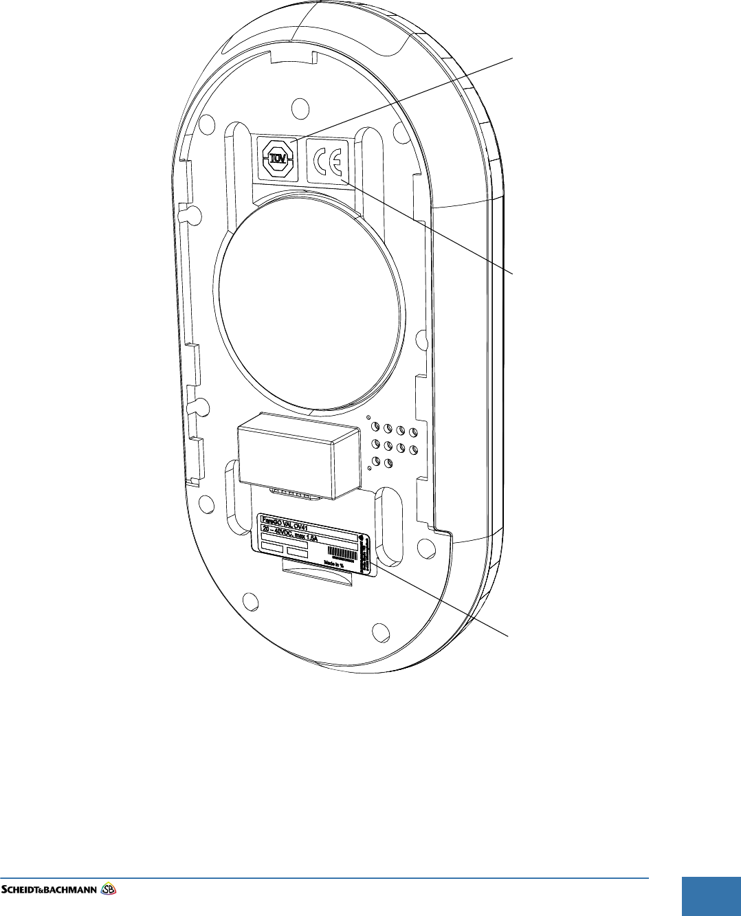
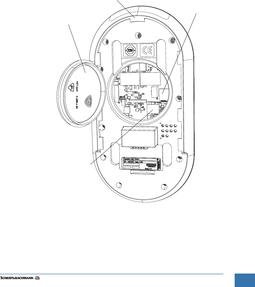
The Labels shown in Figure 1-1 are found inside the device as shown.
Figure 1-1 Label Locations
Serial Number Label
CE Label
TÜV-NRTL Label
Chapter 1
Introduction and Safety Considerations
Edit: Stevens Art.#.: 86 -----, Ver. 1.06 Datum:13.12.2017
1-14
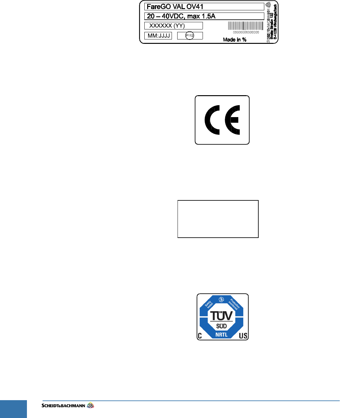
1.0.0.1 Type Label The type label shown in Figure 1-2 appears at the back of the enclosure as
shown in Figure 1-1. This label indicates the voltage range, maximum amperes,
year of manufacture, and manufacturing location as well as the name of the
device and serial number.
Figure 1-2 The Type Label
1.8.1.2 CE Label The CE label shown in Figure 1-3 appears on the backside of the device as
shown in Figure 1-1
Figure 1-3CE Label
1.8.1.3 FCC License
Label
The FCC License label shown in Figure 1-4 appears on the backside of the
device.
Figure 1-4FCC-License
1.8.1.4 TÜV SÜD
NRTL Label
The TÜV-SÜD-NRTL label shown in Figure 1-4 appears on the backside of the
device as shown in Figure 1-1.
Figure 1-5FCC-License
HVIN: OV41
IC: 8312A-NVP
FCC ID: O5K-NVP

Chapter 2
Glossary
Edit: Stevens Art.#.: 86 -----, Ver. 1.06 Datum:13.12.2017 2-15
Fare collection
systems
Chapter 2 Glossary
2.1 Glossary of
Terms and
Abbre-
viations
Many terms and abbreviations are used to describe Fare Collection Equipment.
Some are Automated Fare Collection (AFC) industry standard terms, some are
application-specific, such as networking and telecommunications terms, and
some are unique to the customer’s system.
A
A See “Ampere”.
AC See “Alternating Current”.
Access Level Individual users of a computer system have
specific access rights that regulate what they
can view or modify. Access rights are organized
into groups, which are called Access Levels.
ADA See “Americans with Disabilities Act”.
Alarm Event An alarm event is generally defined as the
unauthorized opening of an AFC device.
Alternating Current An electrical current that continuously changes
polarity or direction of flow, usually 50 or 60
times per second
Americans with Disabilities
Act (ADA)
The federal law mandating facility and equip-
ment accessibility requirements for persons
with disabilities.
Ampere A unit of measure of electrical current, the cur-
rent produced by applying one volt to a circuit
with a resistance of one ohm.
ANSI American National Standards Institute
Application Server NT-based server which runs the Central Data
Collection System Application processes
APTA American Public Transportation Association
ASCII American Standard Code for Information Inter-
change
Audio Speaker A speaker that broadcasts messages in the lan-
guage of choice with content similar to the mes-
sage on the customer display.
AWG American Wire Gauge, a measure of the cross
section of a wire.
B

Chapter 2
Glossary
Edit: Stevens Art.#.: 86 -----, Ver. 1.06 Datum:13.12.2017
2-16
Barcode A barcode is used to encrypt data into a series
of vertical bars (universal product code [UPC]).
It identifies various modules within an AFC
device such as a ticket roll.
Barcode Scanner The Barcode Scanner is a handheld scanner
used to read barcodes (e.g. on replacement
components).
Bitmap Bit-oriented graphics
Blower Also referred to as a “fan,” the blower cools the
Central Processing Unit (CPU) in the ECU.
Boot Loading of the operating system into the RAM
Byte 1 Byte = 8 Bit
C
Card A credit, debit, stored value, or “smart” card
CDCS See “Central Data Collection and Information
System”.
Central Data Collection
System (CDCS)
Centralized company file server that collects
and distributes operating and system fare col-
lection data. The CDCS serves all connected
machines and devices.
Command Instruction to initiate a special transaction
Command Codes See “Service Command”.
CPU Central Processing Unit
CRC Cyclic Redundancy Check. Check sum of the
content of the file.
Customer Display The Customer Display is a part of the user
interface. In some devices, it may include a
touch screen.
Customer Specific Value A data field in which the customer is able to
store individualized information.
D
Database A database is an accumulation of individual
pieces of information that are related to each
other.
Database Server The Database Server is the CDCS hardware
and software system on which the database is
located.
DC Direct Current
DCM Data Control Module; a flash card used to
update equipment in the field.

Chapter 2
Glossary
Edit: Stevens Art.#.: 86 -----, Ver. 1.06 Datum:13.12.2017 2-17
Fare collection
systems
Device Type Device type is a term that refers to categories of
AFC equipment, such as TVMs, TOMs, Fare
Gates, MEMs, etc.
Distance Based Fares Fares that vary in cost with the length of the
trip.
DK Derivation key; the derivation key is used within
the data encryption process.
Download The process of sending information from a host
to a client, enabling client data to be updated.
Driver Software interface which connects devices to
the operating system.
DTE Diagnostic and Test Equipment
E
Electrostatic Discharge
(ESD)
The Electrostatic Discharge symbol indicates
the potential for serious damage to the printed
circuit boards or other Electrostatic Discharge
(ESD) sensitive devices in the device. Ground-
ing precautions must be followed whenever this
symbol appears.
Element.h The element.h file defines elements in service/
statistic printouts.
EPF Ethernet Power Feed; S&B power supply sys-
tem
Error Codes Also called an error message, which is gener-
ated automatically when a particular set of
abnormal conditions occurs. Error information
concerning a system fault or equipment mal-
function can be viewed on the Customer Dis-
play, Service Terminal Display, or on a printed
report.
Error Message See “Error Code”.
ESD See “Electrostatic Discharge”.
Ethernet Card The Ethernet Card is installed in the ECU main
computer. It provides a communications inter-
face between the device and an Ethernet Local
Area Network (LAN).
Event Every action that occurs at or in the TSM is
defined as event.
F

Chapter 2
Glossary
Edit: Stevens Art.#.: 86 -----, Ver. 1.06 Datum:13.12.2017
2-18
FCC Labels Federal Communications Commission (FCC)
labels that identify the license for the transpon-
der identification system. These labels are
located near each transponder, such as on the
Additional Coin Magazine connection board, in
the Coin Magazine Drawer and beside the Coin
Vault.
File Transfer Protocol
(FTP)
The Internet's file transfer protocol. FTP, which
has been used for more than two decades, is a
standard protocol for accessing files on servers
all over the world.
Filter A Filter selects data under special criterion.
Firmware Computer programs and data loaded into read-
only memory that cannot be modified by the
computer during normal operation and that is
not erased by loss of power.
Flash Card The Flash Card is a memory storage module
(PCMCIA) used for device initialization and
backup storage.
FTP See “File Transfer Protocol”.
G
GHz GigaHertz - a unit of measure of electrical fre-
quency equal to one thousand million (1012)
Hertz (cycles per second).
Graphical User Interface The panel and components through which the
customer interacts with the device.
GUI See “Graphical User Interface”.
H
Hexadecimal Numeric system with base 16 (figures from 0 to
15).
Hz A unit of measure of electrical frequency, equal
to one cycle per second.
I
I/O Abbreviation for input/output
ID Abbreviation for “Identification Number”
IEC International Electrotechnical Commission
IEEE Institute of Electrical and Electronic Engineers
ISDN See “Integrated Services Digital Network”.
ISO International Standards Organization

Chapter 2
Glossary
Edit: Stevens Art.#.: 86 -----, Ver. 1.06 Datum:13.12.2017 2-19
Fare collection
systems
K
KB Kilobyte (one thousand bytes, where 1 byte
equals 8 bits)
Keyboard The keyboard is used by the user to enter data
into the system.
kHz KiloHertz – a measure of frequency equal to
one thousand Hertz (cycles per second)
L
LAN See “Local Area Network”.
Language Marker Displays the language the device is equipped
with.
LCD Liquid Crystal Display; see “LCD Display” .
LED Light Emitting Diode
LLRC See “Lowest Level Replaceable Component”.
LLRU See “Lowest Level Replaceable Unit”.
Lmk Check Value The Lmk Check Value images the check sum of
the host security module internal data.
Local Area Network (LAN) A group of interconnected computers located
within the same physical or geographical area
(e.g. within the same building or campus.) See
Wide Area Network.
Login To get access the system, a login with ID and
password has to be completed.
Lowest Level Replaceable
Component (LLRC)
The most basic component that is normally
replaced in the field
Lowest Level Replaceable
Unit (LLRU)
The most basic unit or assembly that is nor-
mally replaced in the field
M
mA Milliampere – a unit of measure of electrical
current equal to one thousandth of an ampere.
An ampere is the current that flows through a
circuit of 1 ohm resistance with a voltage of 1
Volt applied.
MAC Abbreviation for Message Authentication
Codes.

Chapter 2
Glossary
Edit: Stevens Art.#.: 86 -----, Ver. 1.06 Datum:13.12.2017
2-20
mAh An mAh is a milliampere-hour. It is one thou-
sandth of an ampere-hour and is commonly
used as a measure of charge in batteries. An
ampere-hour is the amount of energy charge in
a battery that will allow one ampere of current
to flow for one hour. The HCR battery is rated at
1200 mAh.
Main Circuit Breaker The Main Circuit Breaker, which is located in
the Power Connection Box, protects the system
against high current overload.
Main Module Main Application which controls the Central
Server Application.
Maintenance The action performed to prevent equipment
performance degradation or failure (preventive
maintenance) or restore the device to an in-ser-
vice condition following a failure (corrective
maintenance).
MB Megabyte – one million bytes, where one byte
equals 8 bits.
Mbps Megabits per second – one million bits per sec-
ond
MDT Abbreviation for Mobile Data Transporter.
MSHA Mine Safety and Health Administration
Multimedia Multimedia includes texts, pictures and audio
data.
N
NEMA National Electrical Manufacturers Association
Noise Extraneous or interfering signals present on a
system caused by undesirable voltages or cur-
rents.
NRTL National Registered Test Laboratory
NWC Abbreviation for Network Controller
O
Occupational Safety and
Health Administration
(OSHA)
The United States Government regulatory and
oversight agency responsible for safety in the
workplace.
ODBC Open Data Base Connectivity
OEM Original Equipment Manufacturer
Oersted [Oe] 1 Oersted = 2.021268 Ampere per inch

Chapter 2
Glossary
Edit: Stevens Art.#.: 86 -----, Ver. 1.06 Datum:13.12.2017 2-21
Fare collection
systems
Online/Offline If the TSM is connected to the Network, the net-
work state of the TSM is online, if the TSM is
disconnected, the state is offline.
Oracle Manufacturer of database software.
OSHA See “Occupational Safety and Health Adminis-
tration”.
P
Packet A unit of data routed between an origin and a
destination on any packet switching network.
These “chunks” of data are an efficient size for
routing.
Pass A magnetically encoded document that pro-
vides access to designated portions of the sys-
tem for a specified time period.
Password Every user has his own individual, classified
password that provides access to equipment.
Path The path describes the location of a data file.
PC Personal Computer – a mass-market class of
computer.
PCB Printed Circuit Board
PDU See “Portable Data Unit”.
Permit A fare media element issued to a specific per-
son that identifies that person as authorized for
a reduced fare or adjustment. It is presented
when the person purchases a ticket or pays for
a ride.
PIN Personal Identification Number.
Polling Data transmission initiated by inquiry.
Portable Data Unit A device used to extract data from a farebox for
uploading to the Garage Computer System.
Powerfail Control A possible power failure is monitored by the
system
Primary Key Unique number (index) for a row in the data-
base
Process System Interface The Process System Interface (PSI) is a soft-
ware process that both controls a hardware
component and interprets its state. This pro-
cess is specific to each hardware component.
The PSI, which is responsible for communica-
tion between separate software modules, oper-
ates independently of the operating system.
PROM Programmable Read-Only Memory

Chapter 2
Glossary
Edit: Stevens Art.#.: 86 -----, Ver. 1.06 Datum:13.12.2017
2-22
PSI See “Process System Interface”.
PSI number Address number of the device
Psiboot.bat Helpfile that starts different processes.
Q
QA/QC Quality Assurance/Quality Control

Chapter 2
Glossary
Edit: Stevens Art.#.: 86 -----, Ver. 1.06 Datum:13.12.2017 2-23
Fare collection
systems
R
RAM Random Access Memory
RF Radio Frequency – a high frequency electrical
signal
RGB Video display color standard (Red, Green,
Blue)
ROM Read-Only Memory
RR Abbreviation for railroad
RTTE Radio and Telecommunications Terminal
Equipment Directive = RL 1999/EG) label iden-
tifies the radio license which is used for the
transponder reading transactions. The label is
located on the ACM (Additional Coin Magazine)
connection board.
S
S&B Scheidt & Bachmann
SCR See “Smart Card Reader”.
Service Command The Service Commands are entered into the
service terminal to initiate actions (e.g. prints
error codes, test tickets).
Service Text Service Text appears on the display inside of
the device (TVM) or on the agent display
(TOM).
Smart Card Reader A device that reads the encoded value stored
on a smart card.
Speaker See “Audio Speaker”.
Stored Value Card A magnetically encoded ticket or smart card
with a specified dollar value that provides
access to designated portions of the system.
The value on the card is reduced with each
use.
System Devices that are integrated to perform a spe-
cific function, such as the Coin Processing Sys-
tem, Bank Note System, and so on.
T

Chapter 2
Glossary
Edit: Stevens Art.#.: 86 -----, Ver. 1.06 Datum:13.12.2017
2-24
TCP/IP Transmission Control Protocol/Internet Proto-
col. The TCP is a reliable, connection-oriented
protocol that delivers, with virtually no error, a
byte stream originating on one device to
another device anywhere on the Internet. The
IP facilitates this transfer of data by placing the
bytes into packets that are easily transmitted.
Ticket A magnetically encoded plastic or paper docu-
ment used for entrance to the system and for
verification of payment. In general, this term
refers to the physical media, which can be
encoded as a stored value card or a time based
pass.
Ticket Validator A Ticket Validator is a complete, replaceable
module designed to verify the authenticity of a
properly inserted magnetic ticket. Paper tickets
without magnetic strips may not be validated.
The printing components of a Ticket Validator
interface with the CDCS through an device.
Touch Controller Monitors the device Customer Display touch
screen panel. Reports the results of data input
(screen touches) to the Application Software.
(Applies only to systems equipped with Touch
Screen devices.)
Touch Screen A Touch Screen is the component part of the
Customer/Agent Display that detects user input
by sensing a touch (or tap) on specific areas of
a surface wave-sensitive touch panel.
Transponder The Transponder Chip stores the individual ID-
numbers of the Money Modules.
Transponder Reader The Transponder Reader is located in such a
way that it will read and/or recognize the chip
only when the corresponding money module is
correctly positioned.
U
UNIX Operating System.
Upload The process of sending data from the Client to
the Host Computer.
Username Every individual has a unique username that
identifies that person within the system.
V
VAC Volts Alternating Current
Variableelement.vel Fixes the organization and the position of the
components of the freetext record.

Chapter 2
Glossary
Edit: Stevens Art.#.: 86 -----, Ver. 1.06 Datum:13.12.2017 2-25
Fare collection
systems
VDC Volts Direct Current
Version Group of data downloaded to the devices.
VGA Abbreviation for video graphics array
VGA Controller The VGA Controller, located in the ECU Main
Computer, provides the synchronization and
control signals required to generate the video
for the color VGA Customer Display.
W
WAN See “Wide Area Network”.
Watchdog Timer The Watchdog Timer monitors the ECU CPU.
Should the CPU fall into a “dead” processor
loop, the Watchdog Timer instructs the CPU to
re-initialize the ECU and to reboot.
WAV-File File containing audio data.
Wide Area Network (WAN) Spanning a country or continent, a Wide Area
Network is a communication network that
serves geographically separated areas and
locations.
Workstation PC within a network serving as a control, input,
or monitoring device.
Z

Chapter 2
Glossary
Edit: Stevens Art.#.: 86 -----, Ver. 1.06 Datum:13.12.2017
2-26
THIS PAGE INTENTIONALLY BLANK.

Chapter 3
Declaration of Conformity
Edit: Stevens Art.#.: 86 -----, Ver. 1.06 Datum:13.12.2017 3-27
Fare collection
systems
Chapter 3 Declaration of Conformity
3.1 Europe The device complies to the European Directive RED 2014/53/EU
The OV41 use the following radio frequencies in Europe
Characteristic Specification
Radio frequency:
Transmission power:
radio frequency:
Transmission power:
radio frequency:
Transmission power:
2400 - 2483.5 MHz
49 mW
5150-5775 MHz
45 mW
13.56 MHz
1.18 μW
Table 3-2 Operating Characteristics

Chapter 3
Declaration of Conformity
Edit: Stevens Art.#.: 86 -----, Ver. 1.06 Datum:13.12.2017
3-28
3.2 USA/
CANADA
NOTICE:
This device complies with Part 15 of the FCC Rules and with Industry Canada
licence-exempt RSS standard(s).
Operation is subject to the following two conditions:
1. this device may not cause harmful interference, and
2. this device must accept any interference received, including interference that
may cause undesired operation.
Le présent appareil est conforme aux CNR d'Industrie Canada applicables aux
appareils radio exempts de licence. L'exploitation est autorisée aux deux
conditions suivantes:
(1) l'appareil ne doit pas produire de brouillage, et
(2) l'utilisateur de l'appareil doit accepter tout brouillage radioélectrique subi,
même si le brouillage est susceptible d'en compromettre le fonctionnement.
NOTICE:
Changes or modifications made to this equipment not expressly approved by
(Scheidt&Bachmann) may void the FCC authorization to operate this equip-
ment.
Radiofrequency radiation exposure Information:
This equipment complies with FCC radiation exposure limits set forth for an
uncontrolled environment. It also complies with Industry Canada licence-exempt
RSS standard(s).
The radiated output power of the device is far below the FCC radio frequency
exposure limits. Nevertheless, the device shall be used in such a manner that
the potential for human contact during normal operation is minimized.
NOTE: This equipment has been tested and found to comply with the limits for
a Class B digital device, pursuant to Part 15 of the FCC Rules. These limits are
designed to provide reasonable protection against harmful interference in a res-
idential installation. This equipment generates, uses and can radiate radio fre-
quency energy and, if not installed and used in accordance with the
instructions, may cause harmful interference to radio communications. How-
ever, there is no guarantee that interference will not occur in a particular instal-
lation. If this equipment does cause harmful interference to radio or television
reception, which can be determined by turning the equipment off and on, the
user is encouraged to try to correct the interference by one or more of the fol-
lowing measures:
Reorient or relocate the receiving antenna.
Increase the separation between the equipment and receiver.
Connect the equipment into an outlet on a circuit different from that to which
the receiver is connected.
Consult the dealer or an experienced radio/TV technician for help.

Chapter 3
Declaration of Conformity
Edit: Stevens Art.#.: 86 -----, Ver. 1.06 Datum:13.12.2017 3-29
Fare collection
systems

Chapter 3
Declaration of Conformity
Edit: Stevens Art.#.: 86 -----, Ver. 1.06 Datum:13.12.2017
3-30
Chapter 4
Troubleshooting and Module Removal
Edit: Stevens Art.#.: 86 -----, Ver. 1.06 Datum:13.12.2017 4-31
Fare collection
systems
Chapter 4 Troubleshooting and Module Removal
4.1 Trouble-
shooting
Overview
This chapter provides information about OV|41 error and failure identification.
The first indication of a problem is usually a message displayed on the LCD
screen. Responding to an error involves identifying the nature of the error and
taking appropriate action to finish the transaction. Responding to a failure
involves identifying the nature of the failure and taking appropriate action to
restore the OV|41 to service. When service cannot be restored, the module
needs to be replaced with an operational one.
To reiterate what is said in the preceding paragraph, a maintenance technician
should troubleshoot OV|41 errors by:
Making sure the OV|41 can power on.
Making sure the correct software versions are on the OV|41.
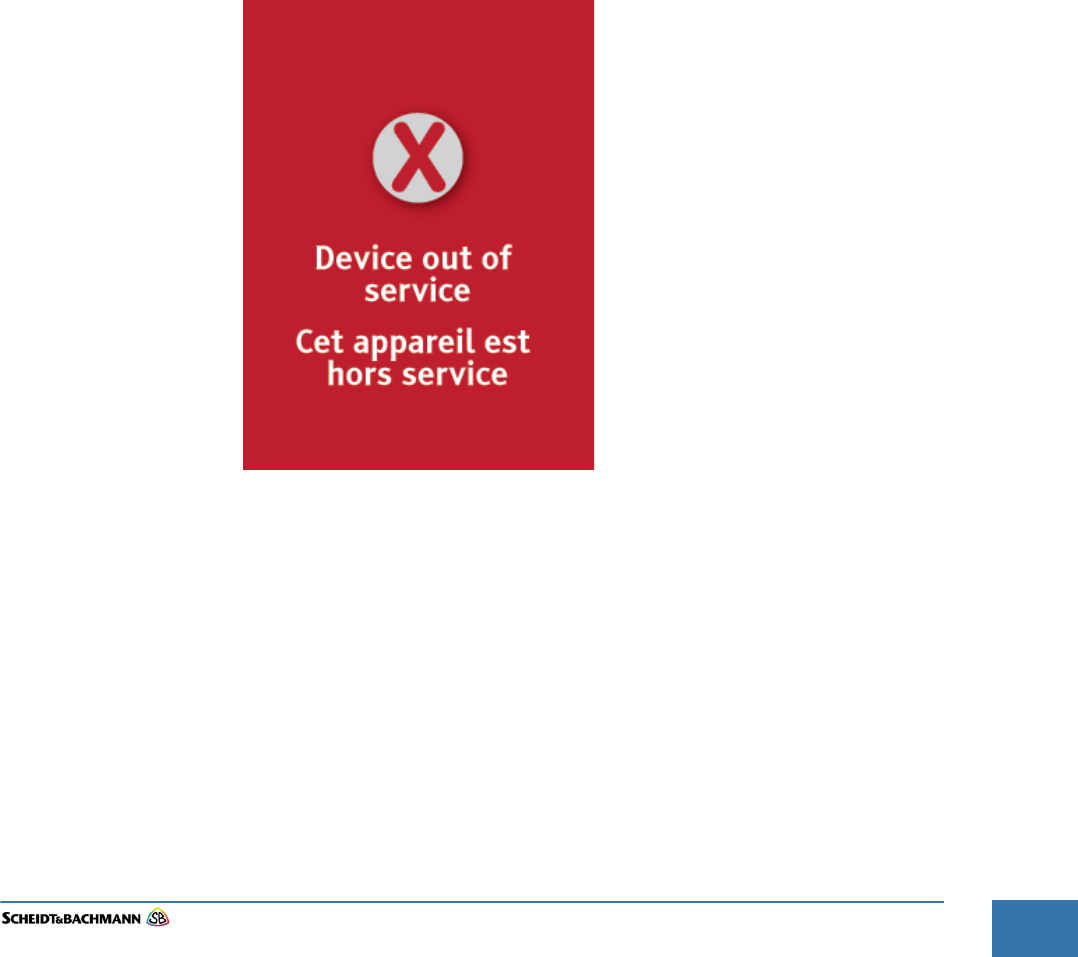
4.1.1 Out of Service Shown in Figure 4-6, the ‘Out of Service’ screen is displayed when the OV|41
is in ‘Out of Service’ mode. The device will not read or write to any Farecards.
Figure 4-6 ‘Out of Service’ Screen
Chapter 4
Troubleshooting and Module Removal
Edit: Stevens Art.#.: 86 -----, Ver. 1.06 Datum:13.12.2017
4-32
When a critical alarm is detected, the OV|41 switches to Out-of-Service mode.
Possible causes include:
Micro SD-card access failure.
Card reader failure.
No currently active business configuration data or other software versions.
The solution is to remove and replace the OV|41. If the failure persists, contact-
ing the Helpdesk is the appropriate action.
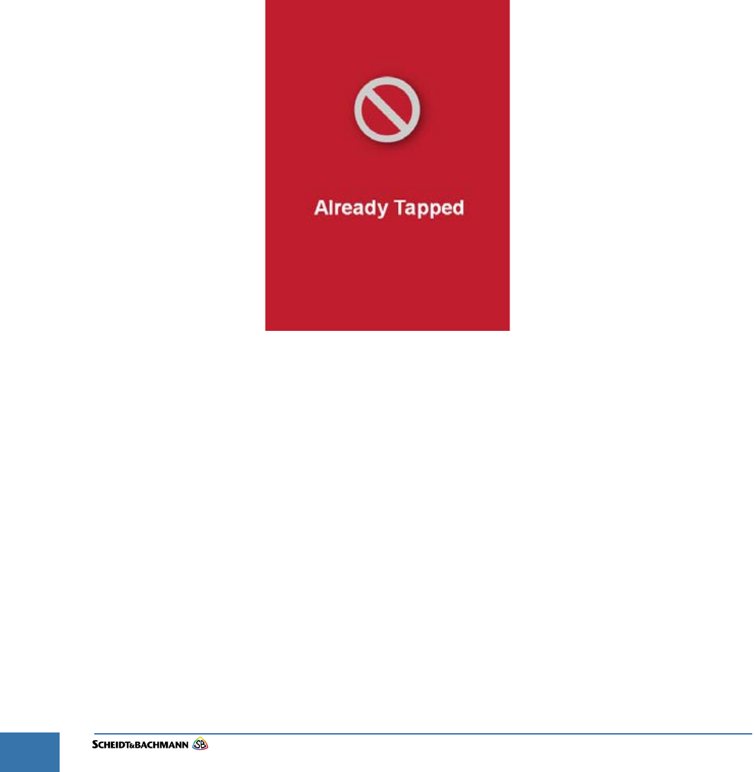
4.2 Error Identi-
fication
When an error occurs, an indication of the error appears on the LCD. This is the
first place to look for messages such as Already Tapped ( Figure 4-7). Errors
interrupt one type of fare transaction.
Figure 4-7 Already Tapped
Chapter 4
Troubleshooting and Module Removal
Edit: Stevens Art.#.: 86 -----, Ver. 1.06 Datum:13.12.2017 4-33
Fare collection
systems
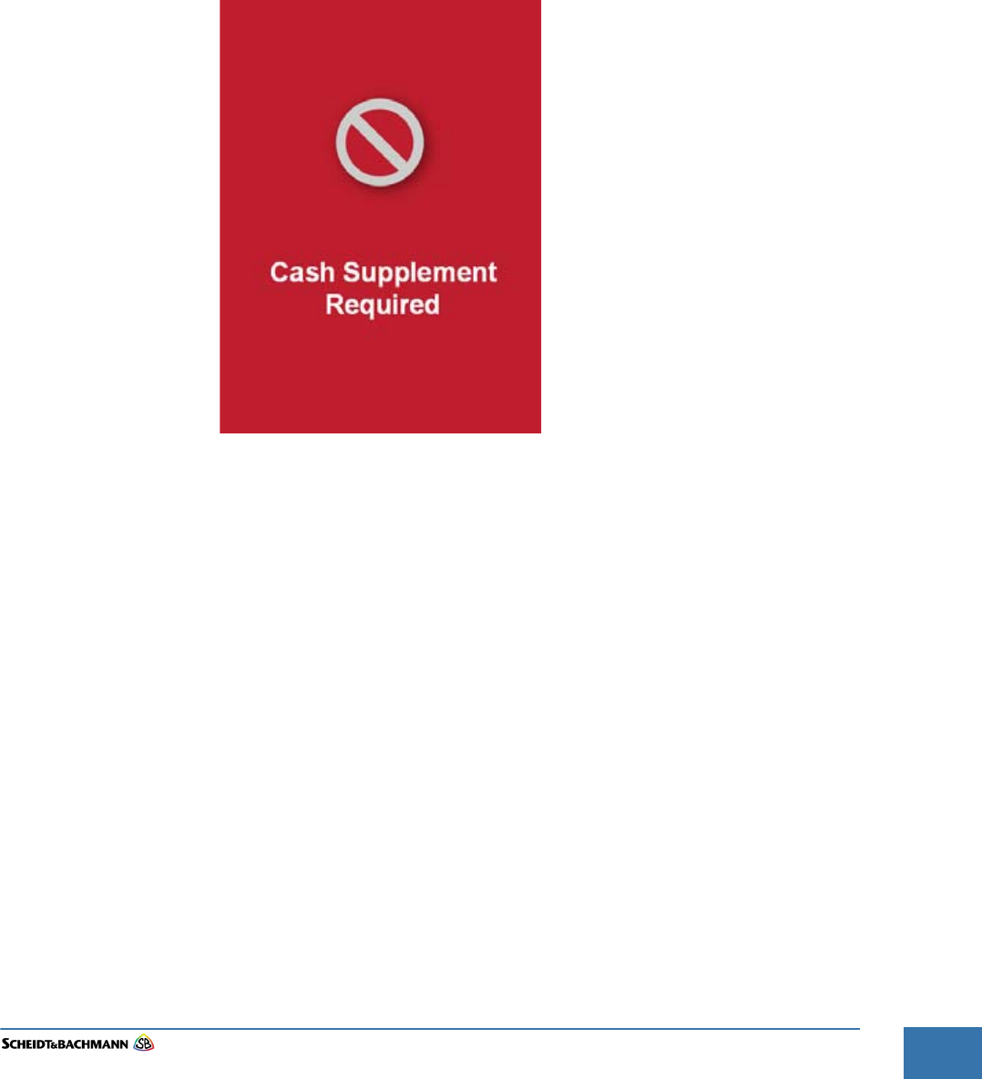
4.0.1 Cash
Supplement
Required
A cardholder may invoke the screen shown in Figure 4-8 under four sets of cir-
cumstances. These are:
Tapping a Farecard with a Period Pass where Cash Supplement is required,
Tapping an STO card with a valid Period Pass where a Cash Supplement is
required,
Tapping a Farecard with a Transfer Product where Cash Supplement is
required, or
Tapping an STO card with a Transfer Product where Cash Supplement is
required.
Figure 4-8 Cash Supplement
Chapter 4
Troubleshooting and Module Removal
Edit: Stevens Art.#.: 86 -----, Ver. 1.06 Datum:13.12.2017 4-35
Fare collection
systems
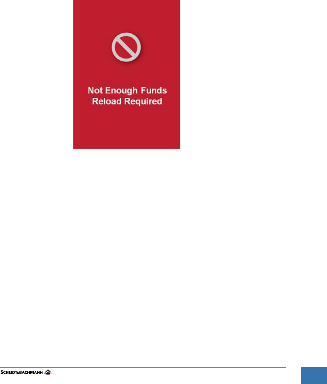
4.0.3 Not Enough
Funds, Reload
Required
There are three circumstances when a cardholder may invoke the screen shown
in Figure 4-10. These are:
Tapping a registered Farecard with a negative e-Purse,
Tapping an anonymous Farecard with a zero e-Purse,
Tapping an anonymous Farecard with a positive e-Purse that is less than the
fare.
Figure 4-10 Funds Lacking
Chapter 4
Troubleshooting and Module Removal
Edit: Stevens Art.#.: 86 -----, Ver. 1.06 Datum:13.12.2017 4-37
Fare collection
systems
4.1 Failure
Identification
When a failure occurs, an indication of the failure appears on the LCD. This is
the first place to look for messages such as Blocked Card.
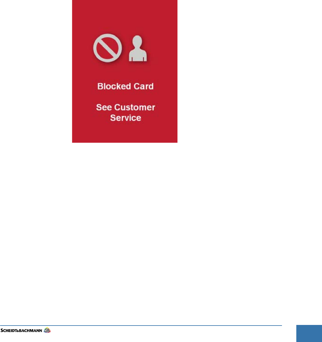
4.2.1 Blocked Card A failure occurs when a Farecard tap on fails. The issue may be one of the fol-
lowing:
Blocked Farecard,
A Farecard that has not been activated, or
A card read/write error.
When a cardholder taps a blocked Farecard, a blocked card, a Hotlisted Fare-
card, or a Hotlisted STO card on the OV|41, the screen in Figure 4-12 appears.
Figure 4-12 Blocked Card
Chapter 4
Troubleshooting and Module Removal
Edit: Stevens Art.#.: 86 -----, Ver. 1.06 Datum:13.12.2017
4-38
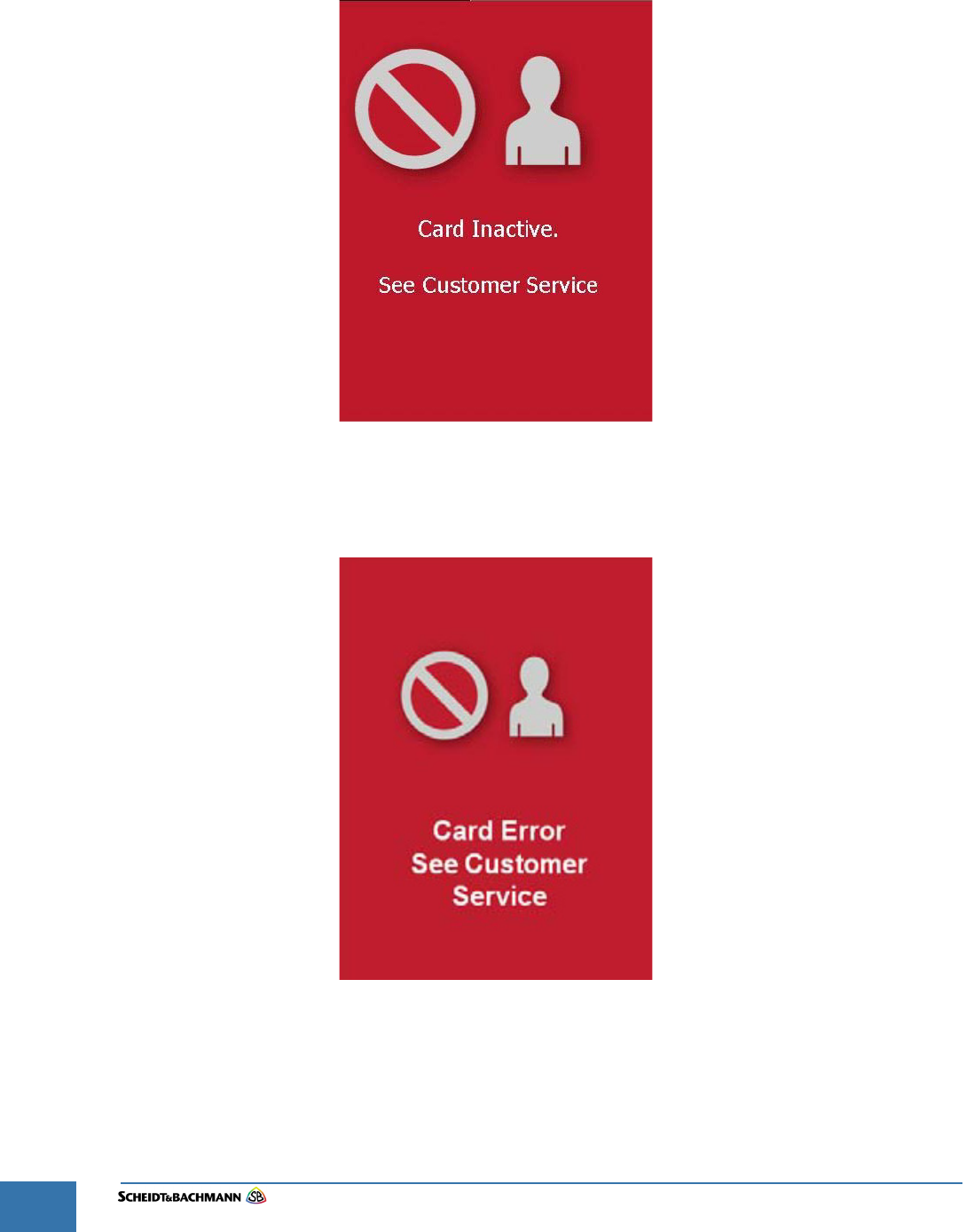
4.1.1 Card Inactive When a cardholder taps a not activated Farecard on the OV|41, the screen
shown in Figure 4-13 appears.
Figure 4-13 Card Inactive
4.2.2 Card Error When a cardholder taps an invalid WMATA Farecard, the screen in Figure 4-14
appears.
Figure 4-14 Card Error
Chapter 4
Troubleshooting and Module Removal
Edit: Stevens Art.#.: 86 -----, Ver. 1.06 Datum:13.12.2017 4-39
Fare collection
systems
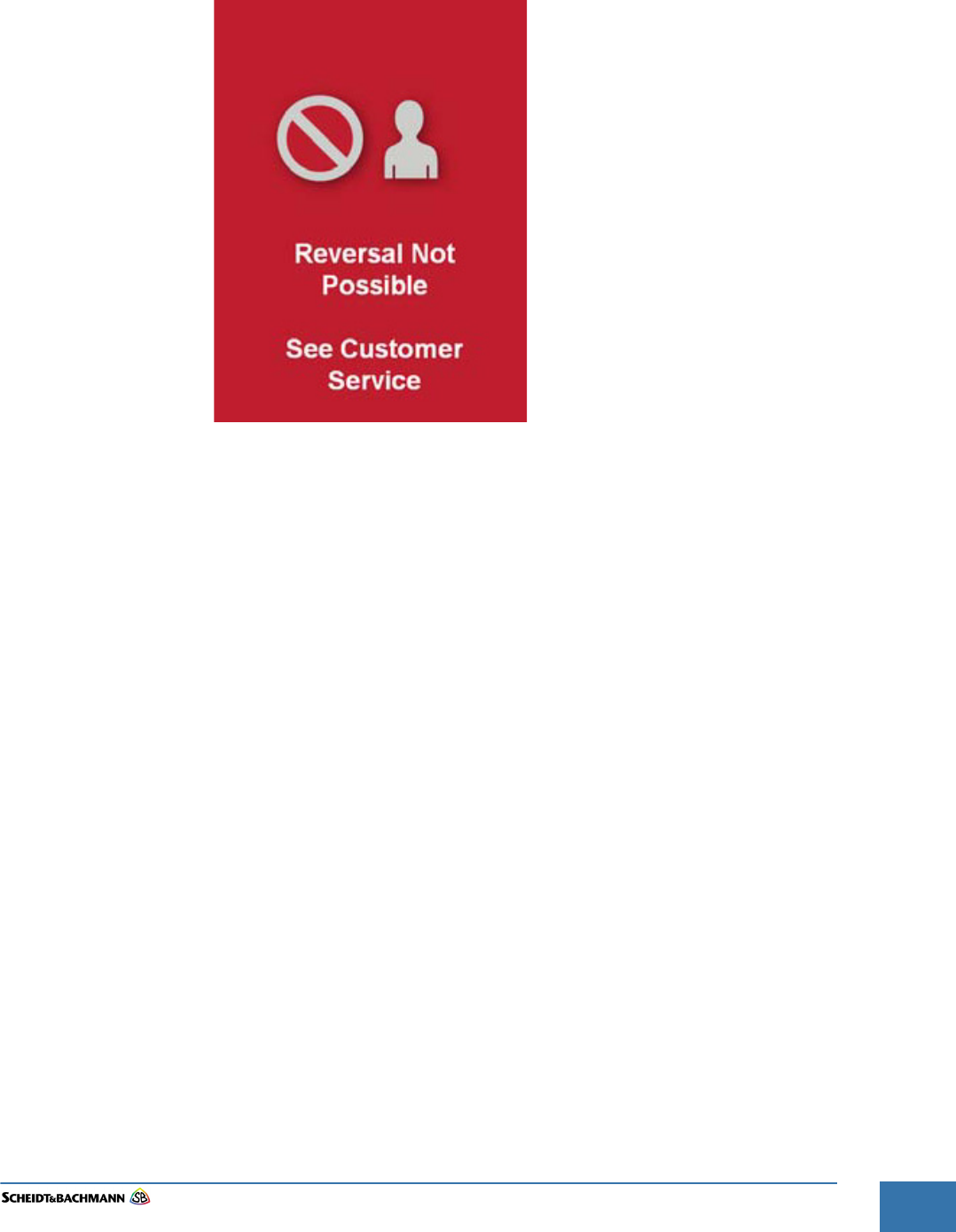
4.1.2 Reversal Not
Possible
When a cardholder tries to reverse a fare payment via the OV|41 where fare
reversal is not processed, the screen in Figure 4-15 appears.
Figure 4-15 Reversal Error
Chapter 4
Troubleshooting and Module Removal
Edit: Stevens Art.#.: 86 -----, Ver. 1.06 Datum:13.12.2017
4-40
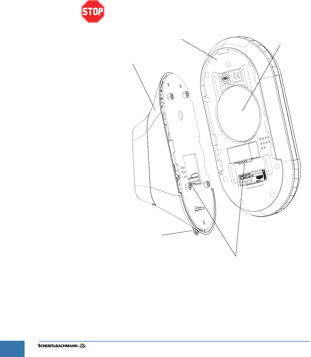
4.2 Module
Removal -
Base Unit
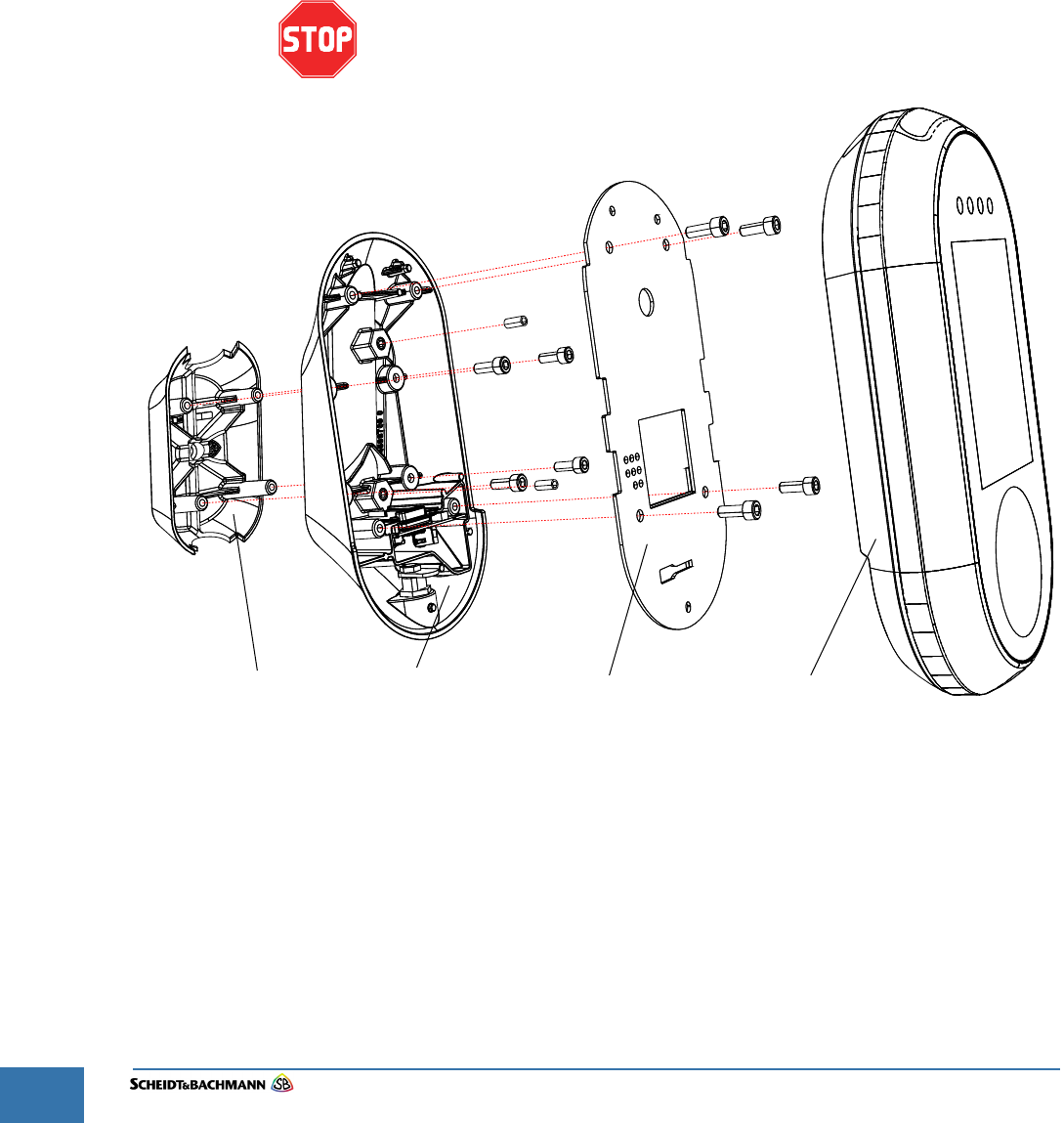
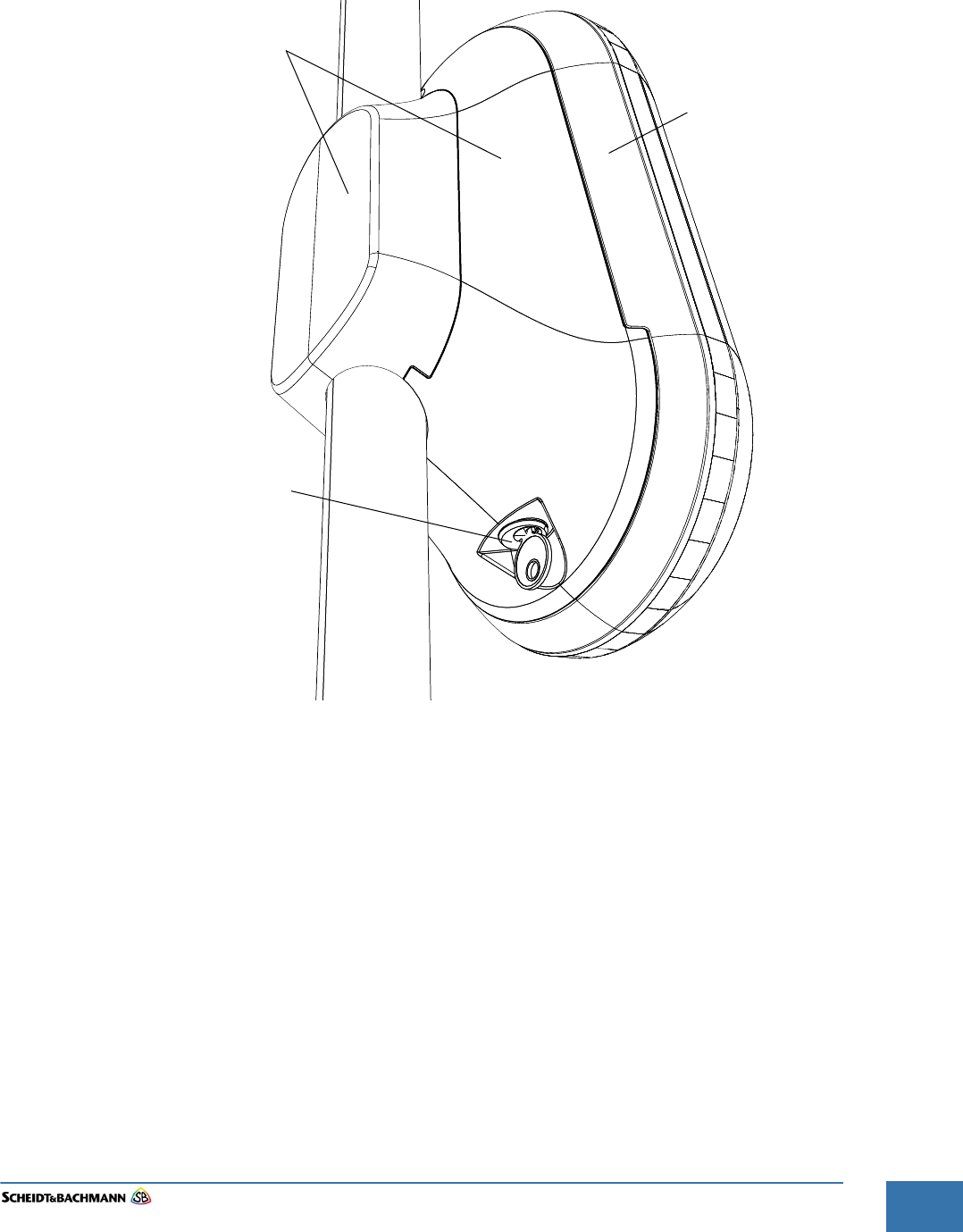
The drawing in Figure 4-16 illustrates how to unlock the OV|41Base Unit and
remove it for field replacement.
STEP 1: Use the key to unlock the device.
STEP 2: Push the Base Unit so fare upward, that the OV|41 can take away from the
mounting unit.
At no time should the service provider open the device to troubleshoot,
repair, or replace OV|41 components in the field.
Figure 4-16 Module Removal - Base Unit
NOTE: As a backup to the online data transmission, a second, pre-configured
Micro SD card may be inserted into the OV|41 (different from the backup
module Micro SD-card). This second, pre-configured card may be used if
the OV|41 is not online or cannot connect to the back end. Transaction
data is also stored in the non-volatile system memory (flash memory).
Base Unit
Mounting Unit
Key
Service
Cover
Connector
Chapter 4
Troubleshooting and Module Removal
Edit: Stevens Art.#.: 86 -----, Ver. 1.06 Datum:13.12.2017 4-41
Fare collection
systems
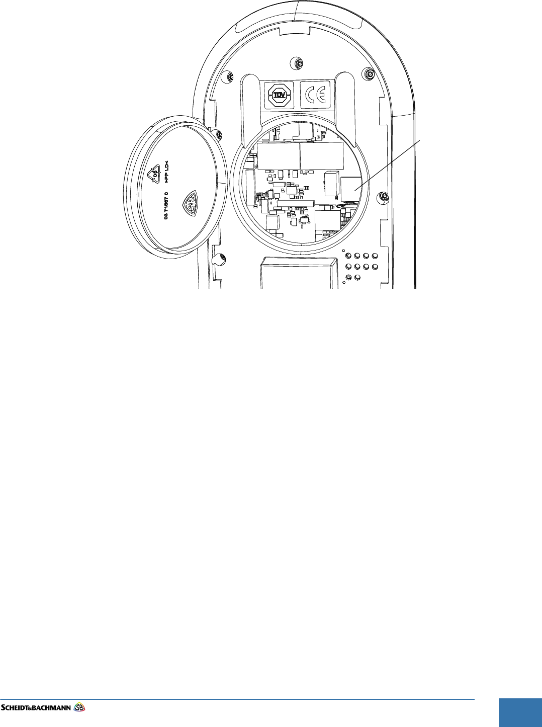
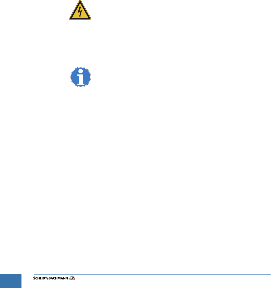
STEP 3: Open the service cover.
STEP 4: Remove the Backup microSD Card as shown in Figure 4-17.
STEP 5: Insert the MicroSD Card in the replacement OV|41.
STEP 6: Set the base unit on the mounting unit and push it down.
STEP 7: Lock the base unit by turning the key showing in Figure 4-16.
Figure 4-17 Service Cover - open
Base Unit
Service Cover
microSD
Card
microSD
Card
Backup
CPU module
Chapter 4
Troubleshooting and Module Removal
Edit: Stevens Art.#.: 86 -----, Ver. 1.06 Datum:13.12.2017
4-42
4.3 Module
Removal -
Mounting Unit
The drawing in Figure 4-18 illustrates how remove the OV|41 mounting unit
from the mounting bar.
STEP 1: Remove the base unit from the mounting unit as shown in Chapter 4.2.
STEP 2: Cut the cable tie and remove the power/network cable as shown in Figure 4-19.
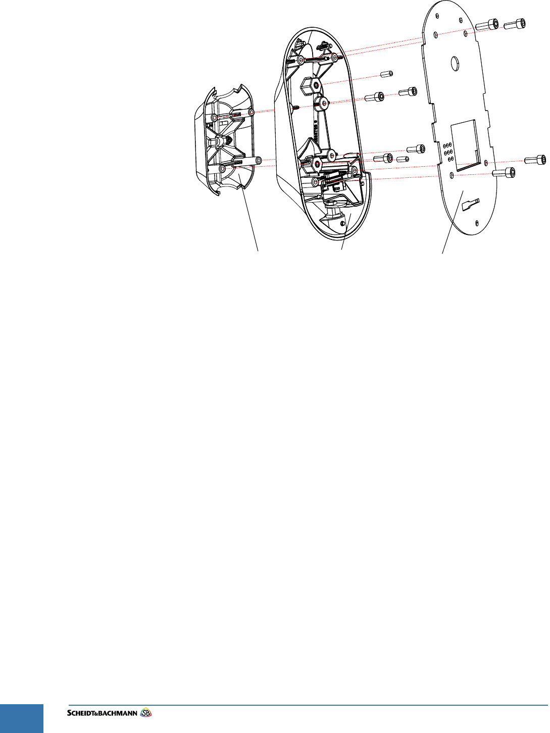
STEP 3: Remove the four screws which fix the mounting plate to the mounting unit front
part and remove the mounting plate.
STEP 4: Remove the four screws which fix the mounting unit rear part to the mounting
unit front part and remove the mounting unit parts from the mounting bar.
Be careful when removing the mounting unit front part. When you push the
Front part up or down you can damage the Power/network cable.
Figure 4-18 Module Removal - Mounting Unit
Mounting Plate
Mounting Unit
Front Part
Mounting Unit
Rear Part
14 Nm
14 Nm
10 Nm 10 Nm
10 Nm
10 Nm
10 Nm 10 Nm
10 Nm
10 Nm
Base Unit
Chapter 4
Troubleshooting and Module Removal
Edit: Stevens Art.#.: 86 -----, Ver. 1.06 Datum:13.12.2017 4-43
Fare collection
systems
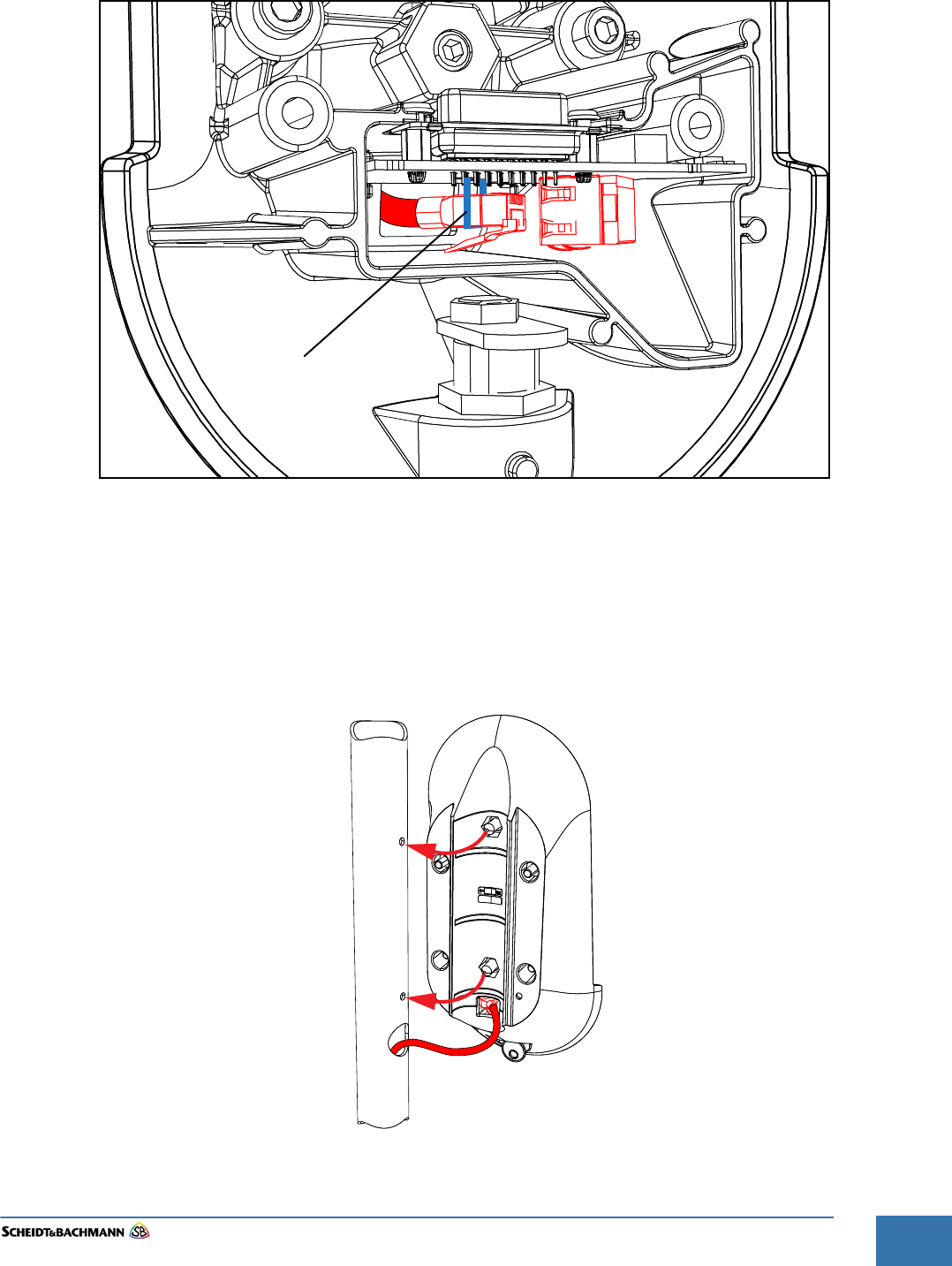
Figure 4-19 Wiring Connections
STEP 5: Place a new OV|41 mounting unit near the proper mounting position and
connect the power/network cable as shown in Figure 4-19.
STEP 6: Secure the plug to the circuit board by a cable tie
STEP 7: Put the OV|41 in the proper mounting position on the mounting post as shown in
Figure 4-20.
Figure 4-20 Wiring Connections
Cable Tie

Chapter 4
Troubleshooting and Module Removal
Edit: Stevens Art.#.: 86 -----, Ver. 1.06 Datum:13.12.2017
4-44
STEP 8: Set the mounting unit rear part on the mounting unit front part and fix it with the
four screws shown in Figure 4-18
STEP 9: Set the mounting plate on the mounting unit front part and fix it with the four
screws shown in Figure 4-18
STEP 10: Install the base unit as shown in Chapter 4.2.
Replacement devices will be pre-initialized. The system provider is not respon-
sible for either initialization or creation of system initialization modules.
NOTE: The back-up module holds the last shift data and the device ID only.
No configuration is needed for creation of the device back-up module. Use an
empty micro SD card, insert in the slot, power on the device. The device will rec-
ognize the empty micro SD card and will initialize it automatically. If the device
detects a non-empty micro SD card, the device will reject the micro SD card and
remain out of service. The device initialization through the back-up module will
be completed with a synchronization through IVN. Spare back-up modules
(micro SD cards) will be provided with each spare device. The service provider
is responsible for providing additional spare back-up modules
If the device is faulty, transfer the faulty device’s back-up module to the new
replacement device. There will be no loss of device data. Avoid using an empty
back-up card. Only use an empty card during a device swap if the original back
up module is lost, defective, or the entire device/back-up combination is not
available. Maintenance staff should be careful not to damage or lose back-up
modules when swapping faulty devices, because all backed up data will be lost.
Users may determine if a device back-up module is faulty by checking the Back-
end system.
Chapter 4
Troubleshooting and Module Removal
Edit: Stevens Art.#.: 86 -----, Ver. 1.06 Datum:13.12.2017 4-45
Fare collection
systems
Figure 4-21 MicroSD Card
4.2.3 Recovery
Scenarios
If the OV|41 is faulty and the Back-up MicroSD card is still intact, follow Recov-
ery Scenario 1. If the MicroSD card is lost, damaged, or defective but the OV|41
is functional, follow Recovery Scenario 2. If both the OV|41 and the Backup
MicroSD card are damaged (a double failure), follow Recovery Scenario 3.
4.2.3.1 Recovery
Scenario 1
When the OV|41 is faulty and the Backup MicroSD Card is still intact, follow
these steps.
STEP 1: Remove faulty OV|41 from the bus (unplug data (Cat-6 cable) and power –
remove from the pole).
STEP 2: Remove the Backup MicroSD card from the malfunctioning OV|41 (spring
loaded, pressing it down will pop it up for removal). It is a small module; be
careful handling it.
STEP 3: Install new OV|41 on the bus (following the standard installation process).
STEP 4: Insert the working MicroSD Backup card (from faulty OV|41) into the new OV|41
(left slot).
STEP 5: Turn on the OV|41 (hook up data and power cables and re-attach to pole).
STEP 6: OV|41 goes through a recovery process (configures IP, data, transactions, etc.).
STEP 7: OV|41 will reboot after the recovery process. At this point the device is identical
to the failed one.
STEP 8: Turn on the device and sync to Backend system (to receive updated lists /
version data) – confirm that the OV|41 is operational and communicating online.
STEP 9: DATA STATUS: NO data loss.
microSD
Card
Backup
Chapter 4
Troubleshooting and Module Removal
Edit: Stevens Art.#.: 86 -----, Ver. 1.06 Datum:13.12.2017
4-46
4.2.3.2 Recovery
Scenario 2
If the MicroSD card is lost, damaged, or defective but the OV|41 is functional, fol-
low these steps.
STEP 1: Open the OV|41 cover. If necessary, remove the faulty backup module.
STEP 2: Insert a formatted new MicroSD-Card. The device auto recovery function will
copy the correct Backupmodul.ini file onto the new card (ini file is now also
saved on device internal hard disk) and backup the data.
STEP 3: DATA STATUS: NO data loss - All transaction data will be retrieved from the
working OV|41 and uploaded to the Backend system.
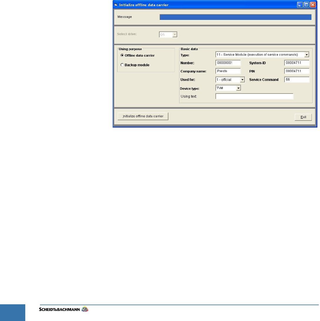
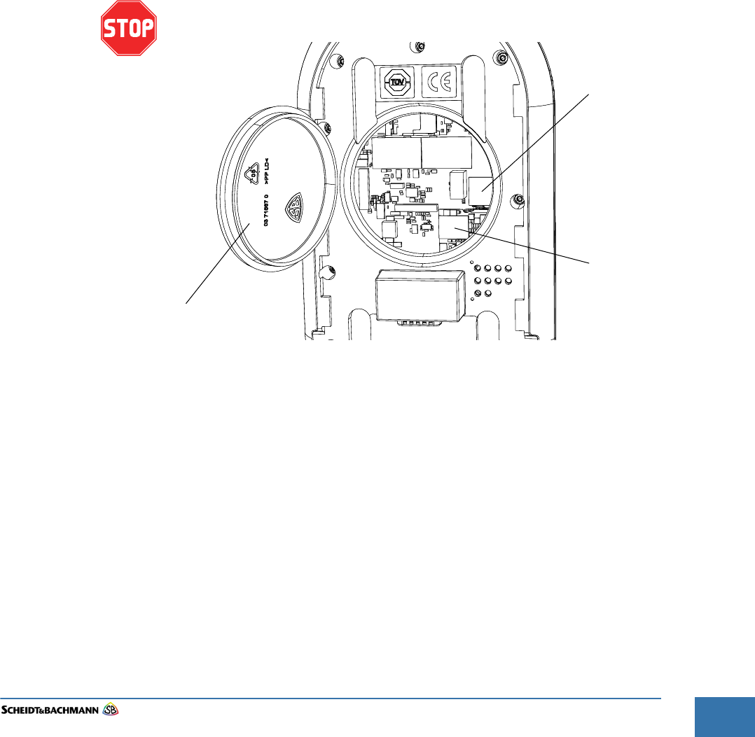
If Manual Data Recovery must be attempted, follow these steps.
STEP 1: Create a Service Modul to execute the Service Command automatically on the
Device. This may be created on Backend system in Offline Modul processing.
Figure 4-22 Initialize Offline Data Carrier
STEP 2: The Procedure on the Device is the same as in Recovery Scenario 1.

Chapter 4
Troubleshooting and Module Removal
Edit: Stevens Art.#.: 86 -----, Ver. 1.06 Datum:13.12.2017 4-47
Fare collection
systems
4.3.0.1 Recovery
Scenario 3
If both the OV|41 and the Backup MicroSD Card are damaged (a double failure),
follow these steps.
STEP 1: Remove the damaged OV|41 from the bus; it needs to be replaced.
STEP 2: Send OV|41 (along with its MicroSD backup module) to Central Repair Depot to
attempt retrieval of the shift files (data recovery may not be possible depending
on the extent of the damage).
STEP 3: Install a new OV|41 on the bus.
STEP 4: Insert new Backup SD card which has the file Backupmodule.ini with the correct
ID setting (this number will be the same as the one on the original backup
module, and can also be seen under Extended Parameters in Device
Maintenance). The OV|41 will configure itself and use the SD card as the backup
module when it is powered on.
STEP 5: DATA STATUS: Possible Loss. The transaction data generated since the last
IVN sync is at risk of being permanently lost in the case of the dual failures of
both the OV|41 and Backup module. If the main logic board of the OV|41 is
intact, or if the SD card can still be read, then data recovery at the Central Repair
Depot may be possible.
Please note: The format for the ID number in the Backupmodule.INI file is as fol-
lows:
AABBBBBBCC, where AA is the provider number (12 for WMATA), BBBBBB is
the 6 digit device ID (such as 020001), and CC is the position in the bus of the
OV|41 (02, 03, or 04). Thus, an example number would be 1202000103. This
information is also available by opening the INI file in notepad, and is easily set.
Here is an example:
Backupmodul.ini Identifier=129999902
Operator ID 12
Busnumber 999999
OV|41 1.
4.3 Verifying
Software
Versions
As a troubleshooting step, a maintenance technician may verify the device soft-
ware versions with the expected version. If the versions are different, the techni-
cian should request that the Backend system Operator confirm that the new
software versions are linked to the device. If so, attempt the device software
download through the Backend system maintenance of jobs.
4.4 Tools and
Con-
sumables
There are no consumables for this device. The only tool is a unique key used to
open and close the device.
Name Part Number
OV|41 Base Unit 00 XXXXX
03 XXXXX
03 XXXXX
Table 4-3 Part Numbers

Chapter 4
Troubleshooting and Module Removal
Edit: Stevens Art.#.: 86 -----, Ver. 1.06 Datum:13.12.2017
4-48
Chapter 5
Preventive Maintenance
Edit: Stevens Art.#.: 86 -----, Ver. 1.06 Datum:13.12.2017 5-49
Fare collection
systems
Chapter 5 Preventive Maintenance
5.1 General
Maintenance
and Cleaning
The following general preventive maintenance procedures are for the overall
maintenance and cleaning of the OV|41. This includes testing and validating the
equipment to ensure proper operation. During this Preventive Maintenance pro-
cess, notify the Network Control Administrator that alarms may be triggered.
Unless otherwise specified, the power must be turned “Off” prior to
performing maintenance procedures.
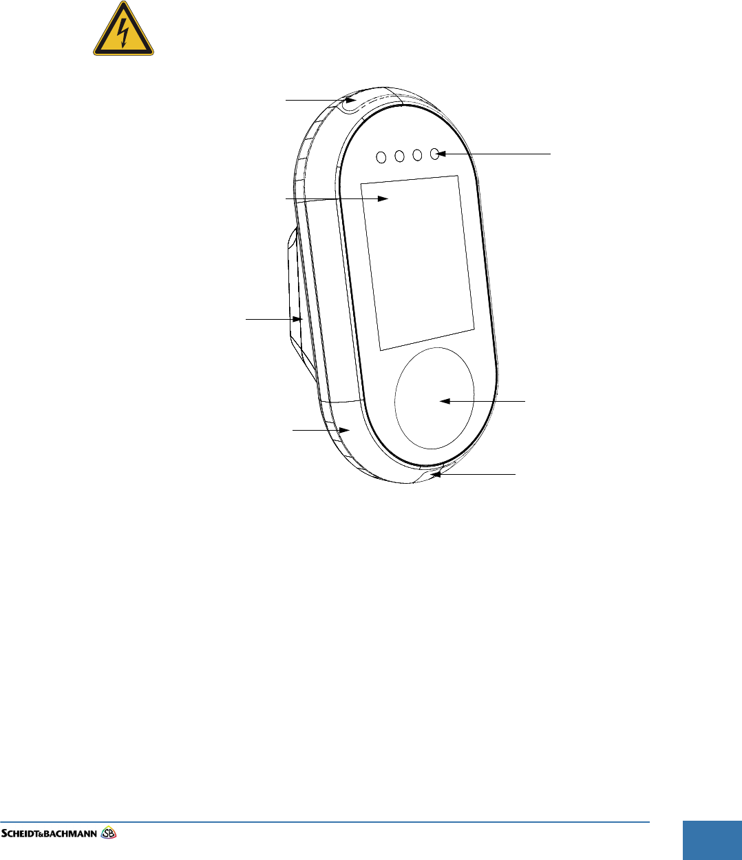
Figure 5-23 OV|41
LCD/Touch Screen
Status LED
Smart Card Area
Open
Payment
Status LED
Barcode Reader
Mounting Unit
(Bracket for Pole)
Base Unit
Chapter 5
Preventive Maintenance
Edit: Stevens Art.#.: 86 -----, Ver. 1.06 Datum:13.12.2017
5-50
5.2 Preventive
Maintenance
Schedule
Summary
The following table is a single source that summarizes all of the preventative
maintenance procedures mentioned in this chapter. Use this table to determine
what procedures that need to be accomplished, and when they should be
scheduled.
When the recommended preventive maintenance intervals have both a
time period and a receipt usage maximum, then preventive maintenance
must take place when either the time or the usage maximum is reached.
These are maximum maintenance intervals, which may have to be
reduced, and they assume average usage in a moderate environment. If
certain devices are heavily used or exposed to atypical environmental
conditions, such as extreme temperature fluctuations or nearby construc-
tion work, then preventive maintenance must be undertaken more fre-
quently in order to reduce the amount and frequency of field
maintenance. Operation and maintenance histories should be consulted
and preventive maintenance procedures undertaken for those devices
and locations where experience shows more frequent preventive mainte-
nance will reduce field maintenance.
5.3 Materials and
Replacement
Parts
Table 13-2 provides a complete list of the materials and replacement parts
needed to perform corrective maintenance on the OV|41.
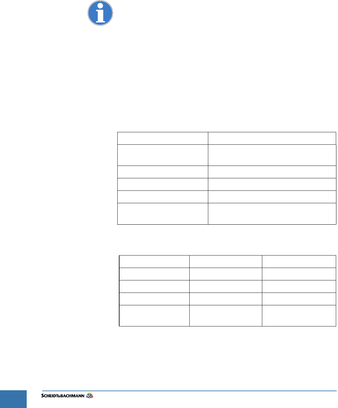
Table 5-4 Recommended Preventive Maintenance Schedule/Frequency
FREQUENCY DESCRIPTION
Every Month Cleaning and Visual
Inspection of the Exterior
Screen Preventive Maintenance
Smart Card Antenna
Lock Preventive Maintenance
Every Three Months Cleaning and Visual
Inspection of the Interior
ITEM PART NUMBER WHERE USED
Canned Air General Use
Alcohol Isopropyl, (70% min.) General Use
Lexan Cleaner Windex (or other mild) Customer Display
Heavy Duty Shop
Cloths
Lint-free, soft Miscellaneous Use
Table 5-5 Materials and Replacement Parts
Chapter 6
OV|41 Installation
Edit: Stevens Art.#.: 86 -----, Ver. 1.06 Datum:13.12.2017 6-51
Fare collection
systems
Chapter 6 OV|41 Installation
6.1 Overview The OV|41 installation instructions described in the this chapter explain how to
install the devices, but do not prepare the devices for operation. Once installa-
tion is complete, the installer should follow the OV|41 Initialization instructions.
The following information and instructions are provided for the installer of a
OV|41.
To avoid damage, deliver OV|41 equipment to the installation location in the
original packaging and Scheidt & Bachmann wrapping.
The OV|41 device is installed inside bus vehicles and provides Farecard
validation.
The OV|41 equipment is fragile. Handle with extreme care. Do not drop!
6.2 Hardware The OV|41 assembly is composed of two main parts:
The OV|41 Base Unit
The Mounting Unit
The Mounting Unit is mechanically fixed onto a pole internally on the bus. The
Mounting Unit supports the OV|41. The OV|41 base unit is securely fixed to the
Mounting Unit.
The internal components of the device are covered by the front and the rear cov-
ers which protect them against vandalism and water. Both covers are screwed
together so that unauthorized access to inner components from outside is not
possible.
6.3 Dimension
and Weight
The dimensions of the OV|41 are in Table 6-6.
The weight of the OV|41 is approximately 4 kg.
6.4 Power
Requirement
s
The power/network connector of the OV|41 is located in the mounting unit and
has a full operating range from 20 VDC to 40 VDC.
Use only S&B EPF systems as power source and CAT6 SFTP cable as wiring.
In standby mode, the OV|41 uses 8 W. In operational mode, the OV|41 uses 12
W.
Height Width Depth
Base Unit 295 mm 155 mm 56 mm
Base Unit incl. Mounting
Unit
295 mm 155 mm 148 mm
Table 6-6Dimensions
Chapter 6
OV|41 Installation
Edit: Stevens Art.#.: 86 -----, Ver. 1.06 Datum:13.12.2017
6-52
The safety labels shown in the section “Device Safety Labels” must be
followed. Review them carefully before proceeding.
Power supply
(
Mode Power Consumption
Standby OV|41 ready to accept Smart Card 8 W
Operational Farecard processing and audio 12 W
NOTE: Use only S&B EPF systems as power source and CAT6 SFTP
cable as wiring
Table 6-7 Power Consumption
Article No. Description
0377252 OV41 Power Box cpl. without CPD
Table 6-8 Power Supply

Chapter 6
OV|41 Installation
Edit: Stevens Art.#.: 86 -----, Ver. 1.06 Datum:13.12.2017 6-53
Fare collection
systems
6.4 Network
Requirements
A NRTL listed, flexible Cat 6 cable will provide data communication and power
supply. The cable complies with NFPA70 and NEC including Chapter 800. The
Ethernet Connector is a standard RJ45.
Figure 6-24 Block Diagram OV|41
Chapter 6
OV|41 Installation
Edit: Stevens Art.#.: 86 -----, Ver. 1.06 Datum:13.12.2017
6-54
6.5 Operating
Features
OV|41 operating characteristics are shown in Table 6-9.
6.5.1 OV|41 Mounting
and
Environmental
Considerations
During transportation and when OV|41 equipment is installed but not opera-
tional, the environmental and storage conditions of Table 6-10 must be met. The
requirements for OV|41 equipment mounting must also be met. Observing these
requirements is the responsibility of the Transit Authority, its architect, and
installers. Minimum clearances, minimum distances from obstructions, place-
ment in a convenient location, and the comfort of the operator are all consider-
ations that should be foremost in the minds of those planning the installation.
The OV|41 should be operated only when “office environmental conditions” exist
in the workplace.
Non-operational environmental and storage conditions must be observed!
Non-operational environmental and storage conditions apply when the
OV|41 is installed but not operational. During operation “Office
Environmental Conditions” must be provided.
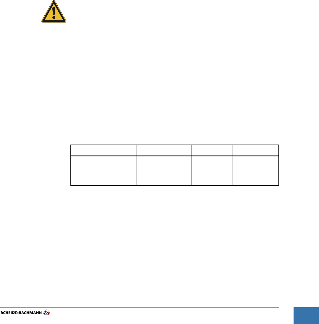
Characteristic Specification
Operating Humidity 10% to 95%, non-condensing
Operating Temperature -30 °C to +50 °C
Power Supply Nominal 24VDC (20VDC to 40VDC)
Power Consumption 12 Watts maximum, 8 Watts standby
Use CAT6 SFTP cable as wiring.
Table 6-9 Operating Characteristics
Environmental Condition Acceptable Range
Temperature Range -40 °C to +70 °C
Humidity 10% to 95%, non-condensing
Table 6-10 Non-Operational Environmental Conditions
Chapter 6
OV|41 Installation
Edit: Stevens Art.#.: 86 -----, Ver. 1.06 Datum:13.12.2017 6-55
Fare collection
systems
6.6 Installation
Requirement
s
The following materials, standard tools, and preconditions are required for
OV|41 installation.
6.6.1 Materials At a minimum, the following materials will be included in the OV|41 package:
1 x Fully Assembled Functional OV|41 unit
6.6.2 Standard Tools Below is a list of required tools and materials:
Small wrench with bit holder
Cable Cutter
Drill
Spiral Drills
Edge Trim for the cable opening
Measuring Tape, minimum 2 meter length
6.6.3 Special Tools Drilling Aid
6.7 Needs and
Requirement
s for OV|41
Installation
The following preconditions must be met by installer before installing the OV|41
(OV|41). The installer must check the following items:
Is there enough space available for the OV|41?
Are all installation components present?
Is a regular metric tool set available? A 174 piece SAE/Metric tool set with
4 drive tools, 10 wrenches, and 121 additional tools, similar to the Alltrade
320329 Tool Set with Tool Box, should have all the necessary tools to
make any adjustments, connections, or installations required.
Is an Ethernet/Power cable with an RJ 45 plug available?
Are a pencil and pad of paper available for note taking, such as noting IP
addresses, and check list verification?
Is the unique key available?
Ensure there is no other cabling in the bus framework that may be
damaged by the installation.
Before starting installation, ensure there is no power on any cable,
breakers are shut off, and all data cabling is disconnected.
Chapter 6
OV|41 Installation
Edit: Stevens Art.#.: 86 -----, Ver. 1.06 Datum:13.12.2017
6-56
Figure 6-25 OV|41 Mounting Unit
6.8 Installation This section gives details related to the mechanical mounting of the OV|41. A
Mounting Unit will be attached to the bus framework. The chosen location is to
be agreed upon between the installation subcontractor and the customer.
The mounting unit of the OV|41 consists of two parts that are mounted together
with four screws ( Figure 6-25). The base unit covers all the electrical compo-
nents. Two fix studs in the front part of the mounting unit will avoid twisting the
OV|41 around the pole. The OV|41 base unit will be secured by a lock under the
mounting unit.
Mounting Plate
Mounting Unit
Front Part
Mounting Unit
Rear Part
Chapter 6
OV|41 Installation
Edit: Stevens Art.#.: 86 -----, Ver. 1.06 Datum:13.12.2017 6-57
Fare collection
systems
Follow these steps to attach a OV|41.
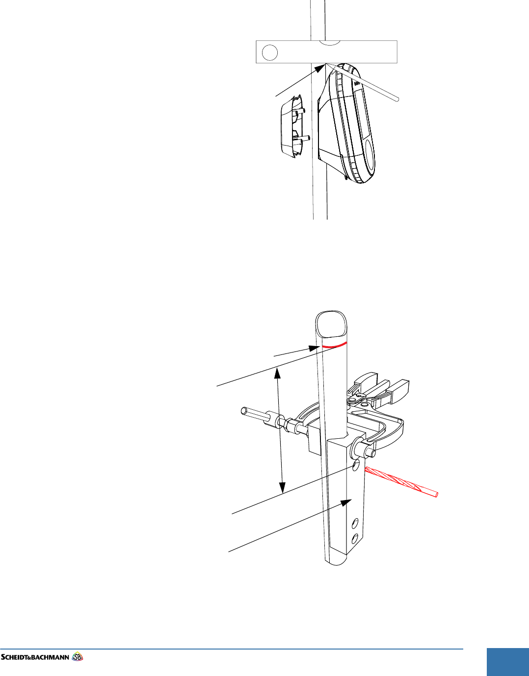
STEP 1: Mark the upper edge of the OV|41 on the pole. (See Figure 6-26)
Figure 6-26 Marking Upper OV|41 Position
STEP 2: Clamp the drilling aid on the pole. The top hole of the drilling aid is located 97
mm from the upper edge of the validator.
Figure 6-27 Marking Upper OV|41 Position
STEP 3: Drill the 5 mm holes for the studs and the cut out for the cable into the pole
(see Figure 6-27 and Figure 6-28).
Upper OV|41 Position
Upper OV|41 Position
97mm
Drilling Aid
Chapter 6
OV|41 Installation
Edit: Stevens Art.#.: 86 -----, Ver. 1.06 Datum:13.12.2017
6-58
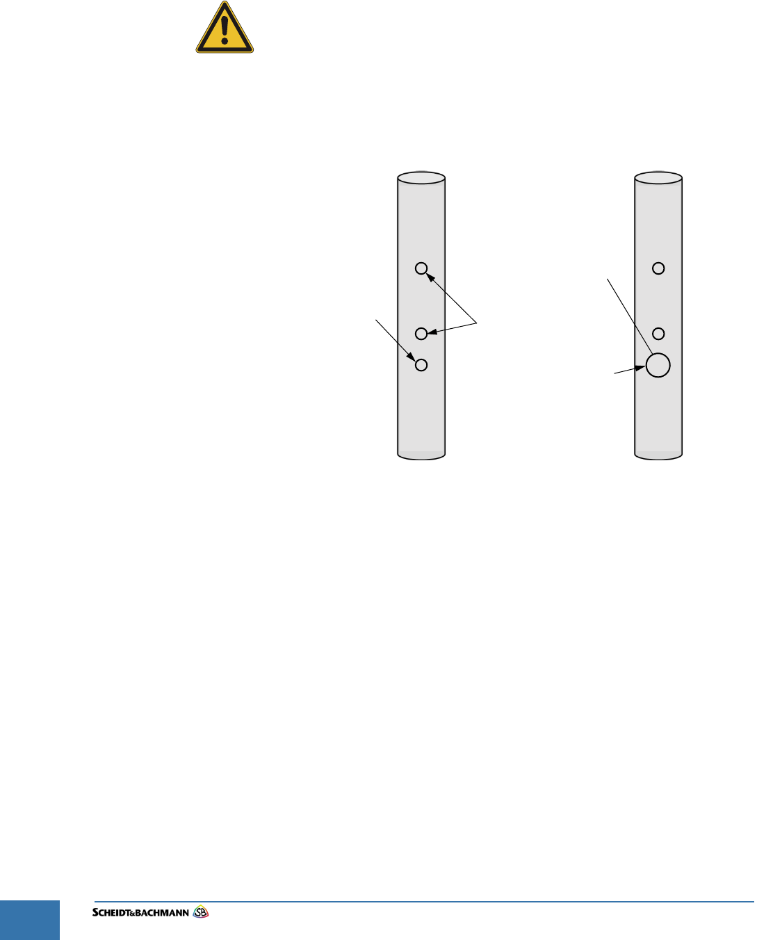
STEP 4: Expand the 5 mm hole for the cable opening (middle hole) as needed for the
existing cable with a appropriated drill.
STEP 5: De-burr all boreholes.
Wear safety glasses when drilling for eye protection!
Grip the drill firmly. If it sticks, it can twist in your hands and cause serious
injury!
STEP 6: Use a trim along the sharp edges of the cable cut out to protect the wiring. This
edge trim must comply with TÜV-SÜD-NRTL R/C QMFZ2 Plastics with a
minimum Flame class HB.
Figure 6-28OV|41 Mounting Openings
STEP 7: Run the Power/Network cable through the pole and pull it out through the cable
opening.
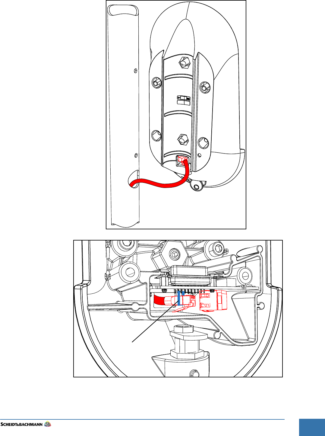
STEP 8: First plug in the cables to the OV|41 mounting part ( Figure 6-29)
STEP 9: Secure the plug to the circuit board by a cable tie see ( Figure 6-29).
STEP 10: and then place the OV|41 onto the pole by inserting the studs in the designated
holes. The studs prevent the OV|41 from twisting on the pole ( Figure 6-30).
Cable Opening
(predrilled 5 mm) Holes for Studs (5 mm)
Cable Opening
(expanded to 18 mm)
Use edge Trim
Chapter 6
OV|41 Installation
Edit: Stevens Art.#.: 86 -----, Ver. 1.06 Datum:13.12.2017 6-59
Fare collection
systems
Figure 6-29Wiring Connection
Cable Tie
Chapter 6
OV|41 Installation
Edit: Stevens Art.#.: 86 -----, Ver. 1.06 Datum:13.12.2017
6-60
NOTE: The cable, must be attached to the back of the OV|41 mounting unit.
Figure 6-30Pole Installation
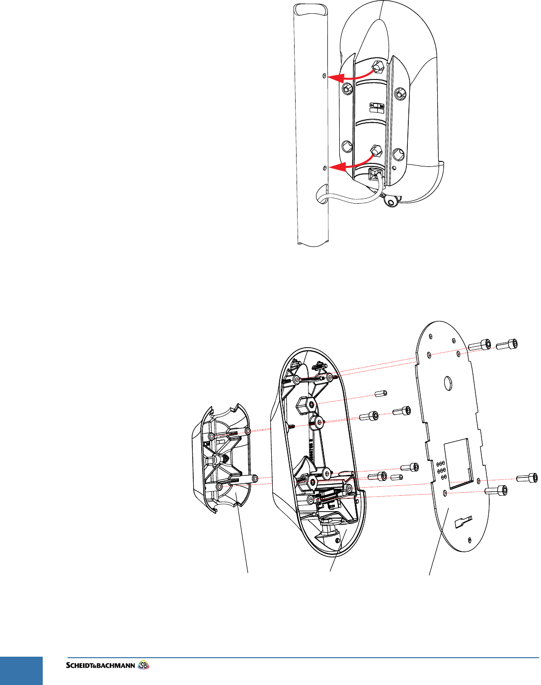
STEP 11: Put the rear part of the mounting unit on the front part of the mounting unit
around the pole and fix it with four screws. (see Figure 6-31).
Figure 6-31Mount the Mounting Unit
STEP 12: Put the mounting plate on the mounting unit front part and fix it with four screws.
Mounting Plate
Mounting Unit
Front Part
Mounting Unit
Rear Part
14 Nm
14 Nm
10 Nm 10 Nm
10 Nm
10 Nm
10 Nm 10 Nm
10 Nm
10 Nm
Chapter 6
OV|41 Installation
Edit: Stevens Art.#.: 86 -----, Ver. 1.06 Datum:13.12.2017
6-62
6.9 Post-
Installation
Checklist
The installer must use the following checklist to verify proper installation of the
OV|41 and associated equipment.
Ensure the stability of the OV|41 on the Pole.
Verify any attached cables are secure.
Ensure there is adequate power and network.
6.10 Disassembly
and Removal
Should it become necessary to remove the complete OV|41 (mounting unit and
base unit) from its permanent location, the following procedure must be fol-
lowed.
Ensure power to all cables is shut off before starting the removal. Breakers
must be shut off and all data cables should be disconnected. Electrical
power must be turned off at the source.
STEP 1: Turn off Main Circuit Breaker.
STEP 2: Disassemble the OV|41in reverse order .
STEP 3: After removing the OV|41, the remaining cables and conduits must be removed
by an authorized worker.
Any questions please contact the Environment Agency on 0XXXX XXX XXX.
Registration Number XXXXXXXX
Chapter 7
OV|41 Initialization
Edit: Stevens Art.#.: 86 -----, Ver. 1.06 Datum:13.12.2017 7-63
Fare collection
systems
Chapter 7 OV|41 Initialization
7.1 Initialization This chapter explains how to initialize the OV|41.
7.1.1 Initialize OV|41
With New
System
Software
To perform a base initialization of a OV|41, follow these steps.
For these procedure the OV|41 must have a connection to the software
server.
STEP 1: Take the base unit from the mounting unit.
STEP 2: Remove the service cover.
STEP 3: Insert the micro SD card containing the new system software into the
"System microSD card" slot (see Figure 7-33).
Refer to Figure 7-33 for the location of the micro SD slot that may be used.
Figure 7-33 Micro SD Card Location
STEP 4: Put the base unit on the mounting unit.
STEP 5: The OV|41 will run through the boot process.
STEP 6: When the device starts up, the SysInit will be downloaded from the software
server.
STEP 7: When the device is starting up, the following screen will be shown:
microSD
Card
Backup
microSD
Card
System
Service Cover
(optional)
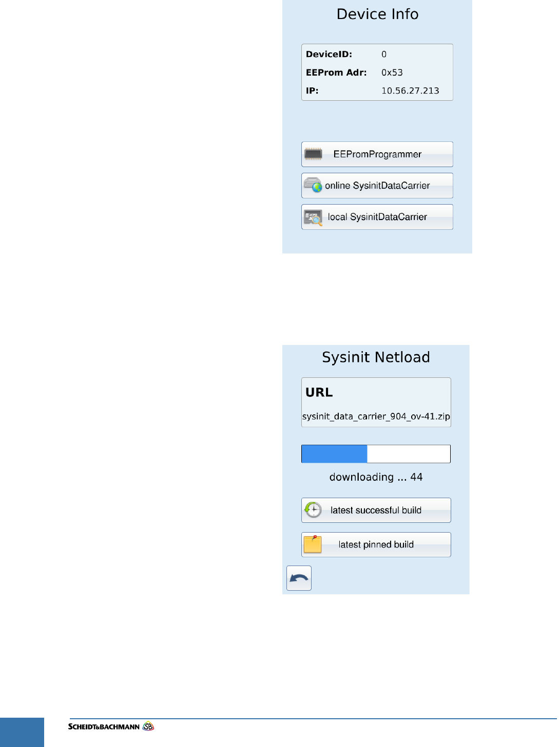
Chapter 7
OV|41 Initialization
Edit: Stevens Art.#.: 86 -----, Ver. 1.06 Datum:13.12.2017
7-64
Figure 7-34 SysInit "IDLE" screen
STEP 8: Choose "online SysinitDataCarrier" to download the latest successful build or
latest pinned build.
Figure 7-35 SysInit "download" screen
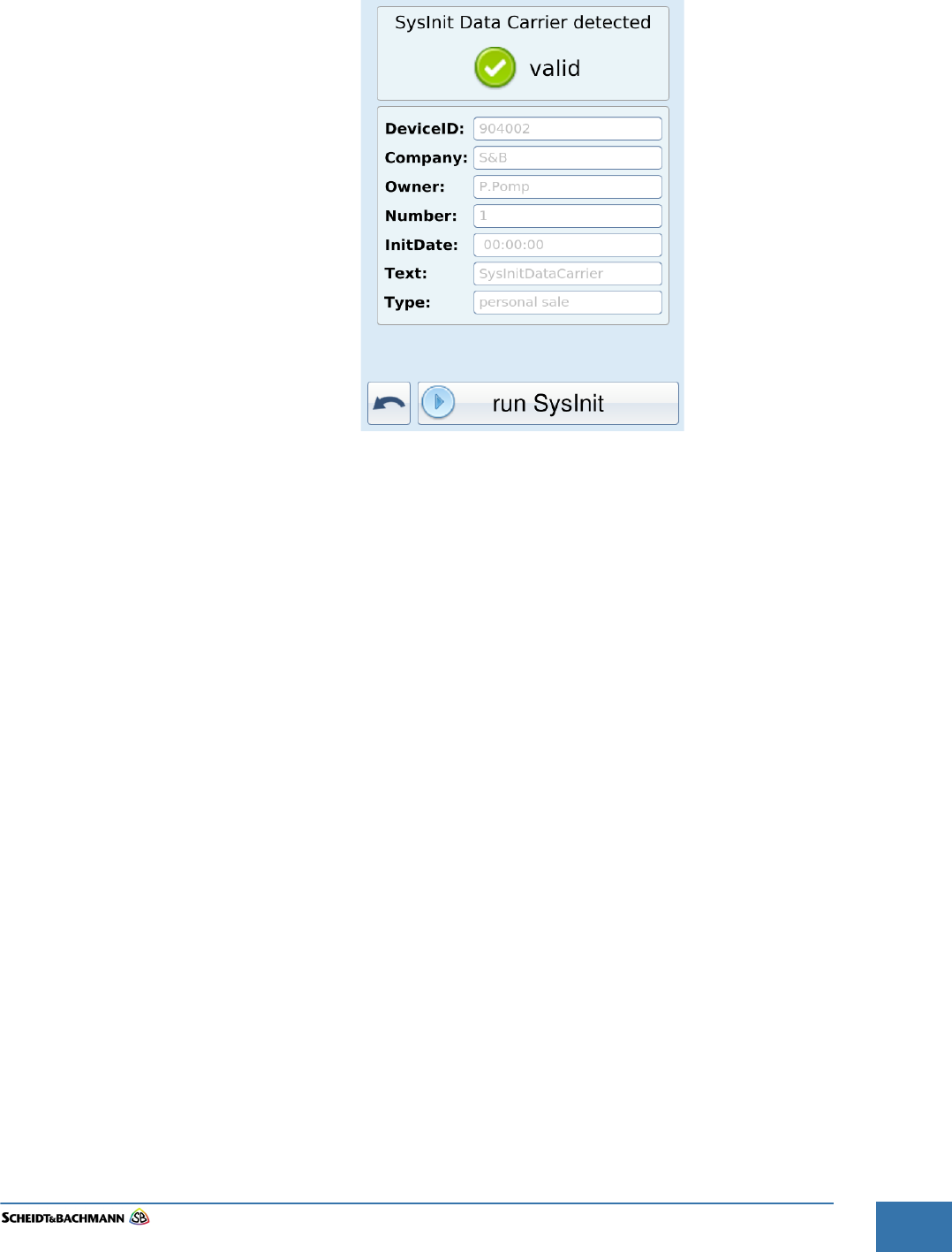
Chapter 7
OV|41 Initialization
Edit: Stevens Art.#.: 86 -----, Ver. 1.06 Datum:13.12.2017 7-65
Fare collection
systems
STEP 9: When the SysInit Data Carrier was successfully downloaded, press "run sysinit".
Figure 7-36 SysInit "run SysInit" screen
STEP 10: After a minute the device will reboot. Now you see the processes starting:
STEP 11: After successful starting of all processes, the customer application will start and
the IDLE screen will be displayed.
sbuser@Trizeps7:~$ psiinfo -l
PSI - Process List
Process-ID Status (Name)
0x00000020 running (PSI Timer Process)
0x00000021 running (Config Process)
0x00000023 running (Powerfail Process)
0x00000027 running (Tcp32 Process)
0x00000031 running (Crypto Process)
0x00001081 running (Version Control [135_1551])
0x00001088 running (Transaction Recorder [177_1349])
0x00001100 running (DeviceControl [169_1481])
0x00001413 running (Event-/Status-Handler)
0x00002100 running (Service Process [127_1352])
0x00003405 running (Production Process)
0x0000340C running (Smart Card Process Version 16.9.26,o,r)
0x00003800 running (Payment)
0x00003806 running (LogicalIO [211_1673:16/11/16_0949])
0x00003C50 running (Filetransfer)
0x00003C51 running (OnlineControl)
0x00004C01 running (PxUSB S&B Smartcard Reader)
0xFFFFFFFC running
0xFFFFFFFE running (Rousnp Process)
Chapter 7
OV|41 Initialization
Edit: Stevens Art.#.: 86 -----, Ver. 1.06 Datum:13.12.2017
7-66
Figure 7-37 Application "IDLE" screen