Schlage Electronic Security PROXIF Door Lock User Manual 51005 D
Schlage Electronic Security Door Lock 51005 D
Contents
- 1. 5100 Manual
- 2. 5500 Manual
5100 Manual
Form 51005 Rev. D 12-02-20022
CM5100 COMPUTER MANAGED CYLINDRICAL LOCK
INSTALLATION MANUAL
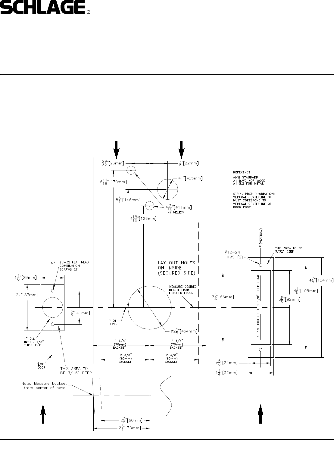
1. PREP DOOR AND FRAME:
A. Determine door hand and correct backset.
B. Mark the horizontal and vertical centerlines for the lockset, latch and strike.
C. Place template on inside of door (opposite the side that the keypad/reader will be on). Line up the correct reference lines
on the template with the edge of the door. The centerline on the door should line up with the vertical centerline of the tem-
plate.
D. Drill holes as described by template.
BEFORE YOU BEGIN:
Standard units are shipped from the factory to fit 1-3/4” doors. Verify that the door thickness. If the door is not 1-3/4” thick,
verify that the door thickness option was ordered or consult factory.
DOOR EDGE (LATCH) FRAME (STRIKE)
DOOR FACE (LAY OUT ON INSIDE)
Form 51005 Rev. D 12-02-20023
CM5100 COMPUTER MANAGED CYLINDRICAL LOCK
INSTALLATION MANUAL
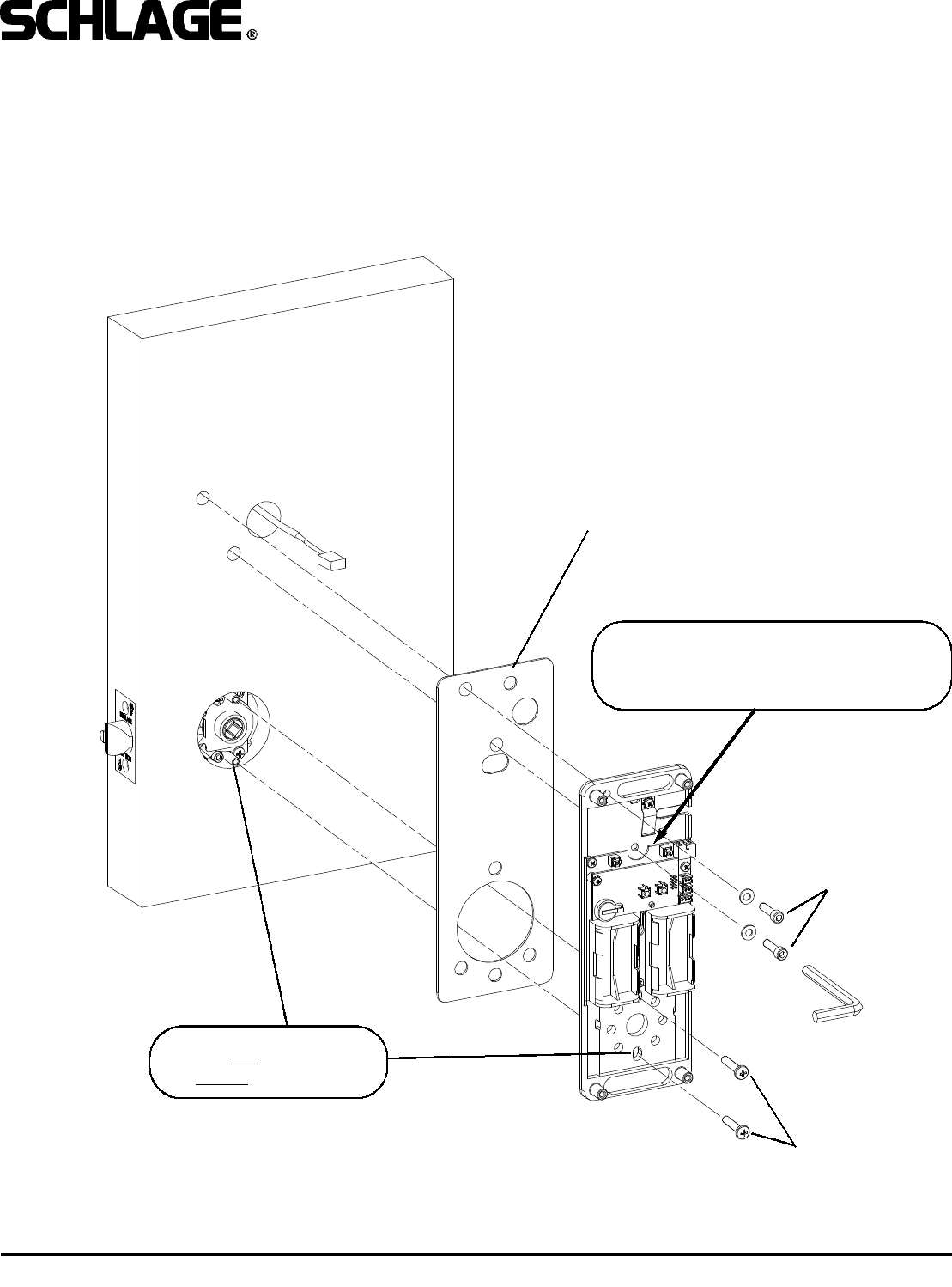
2. INSTALL CYLINDER (IF NOT ALREADY DONE), GASKET AND STANDOFFS:
A. Install cam onto cylinder (if not already done.) Cam must be a straight, 11/16” design. See below for recommended
cams.
B. Insert mortise cylinder into outside escutcheon from front (keypad/reader) side with keyway down.
C. Slide lock washer onto cylinder (tab on top facing out, as shown below.)
D. Using nut tool (provided) tighten nut onto cylinder.
E. Line up nearest notch on nut with tab on lock washer and bend tab using nut tool so nut is secure.
F. Install exterior gasket (if used).
G. Install standoffs.
TEST KEY OPERATION NOW: Turning key clockwise until it stops (about 1/2 turn) should allow the lever to turn retractor.
CYLINDER
RECOMMENDED CAMS:
SCHLAGE EVEREST: P/N B502-948
SCHLAGE CLASSIC: P/N B502-191
NUT TOOL
RETRACTOR ASSEMBLY
LOCK WASHER
NUT
STANDOFFS
EXTERIOR GASKET
TAB
NOTE:
BLOCKING RING REQUIRED FOR CYLINDER
LENGTH GREATER THAN 1-1/8”.
THICKNESS = CYLINDER LENGTH - 1 1/8”
Form 51005 Rev. D 12-02-20024
CM5100 COMPUTER MANAGED CYLINDRICAL LOCK
INSTALLATION MANUAL
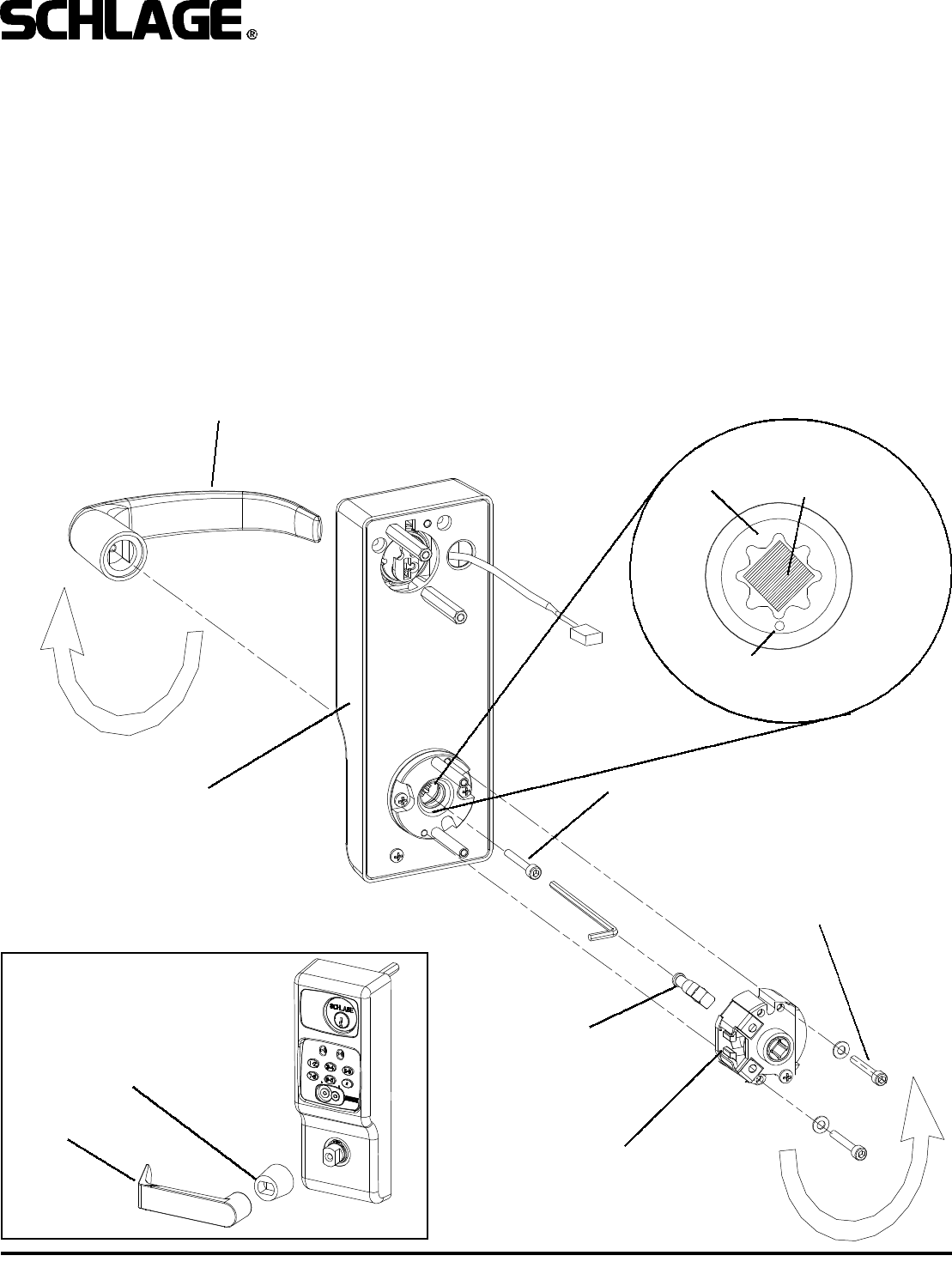
3. CHANGE HAND (IF NECESSARY):
NOTE: The locks are shipped handed as ordered from factory. If it is necessary to change the hand of the lock, follow the
steps below:
A. Remove retractor by loosening two 9/64” socket cap screws which attach it to the outside escutcheon.
B. Remove outside spindle.
C. Loosen 5/32” socket cap screw which secures handle to escutcheon.
D. Remove, rotate and re-install handle (NOTE: some handle designs have an adapter.)
E. Re-install outside spindle, making sure that the round end faces the handle, and the spindle is positioned with its edges
vertical and horizontal as shown in detail below. Note that the cam (inside the escutcheon assembly) must be positioned
such that the dot on it faces the 6 O’Clock position (see detail below).
F. Rotate retractor and re-install it.
G. Change the hand of the handle on the inside escutcheon (not show) the same way. Note that the inside escutcheon has
no retractor.
OUTSIDE ESCUTCHEON
OUTSIDE SPINDLE
(ROUND SIDE TOWARD LEVER)
9/64” SOCKET CAP
SCREW
5/32” SOCKET CAP
SCREW
RETRACTOR
OUTSIDE HANDLE
DOT - FACES
DOWN
OUTSIDE
SPINDLE
POSITION
CAM
DETAIL
ADAPTER
LEVER
NOTE:
Some lever designs
require an adapter.
Form 51005 Rev. D 12-02-20025
CM5100 COMPUTER MANAGED CYLINDRICAL LOCK
INSTALLATION MANUAL
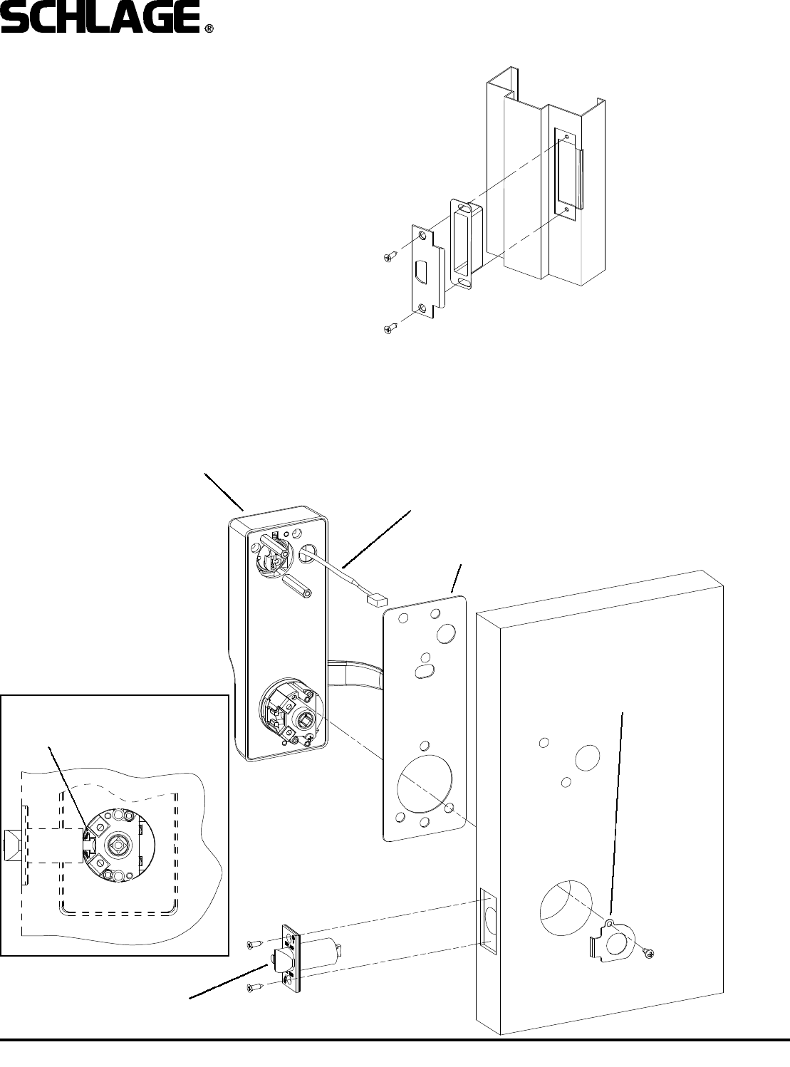
SPACER (FOR DOORS LESS THAN 1-3/4”)
OUTSIDE ESCUTCHEON
LATCH
(INSTALL FIRST)
LATCH GUARD
(INSTALL LAST)
WIRING HARNESS
4. INSTALL STRIKE BOX AND STRIKE:
5. INSTALL LATCH AND OUTSIDE ESCUTCHEON:
A. Install latch into edge of door. Be sure to install it with the beveled edge facing door jamb.
B. If the door is less than 1-3/4 thick, slide spacer over standoffs and retractor on outside escutcheon.
C. Carefully install the outside escutcheon onto the door, passing the wiring harness through the 1” hole. Be sure that the
prongs on the latch engage with the retractor as shown in detail below.
D. Install latch guard from inside of door. (Do not install latch guard first or retractor will not clear the latch.)
DETAIL
Prongs must engage
with retractor.
Form 51005 Rev. D 12-02-20026
CM5100 COMPUTER MANAGED CYLINDRICAL LOCK
INSTALLATION MANUAL
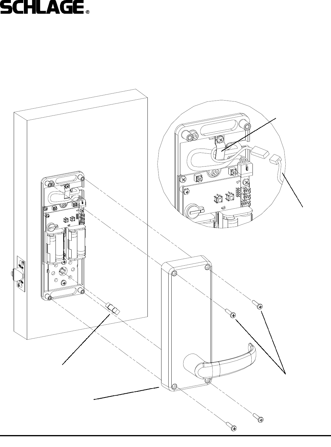
6. INSTALL BASE PLATE ASSEMBLY:
Install base plate assembly onto inside of door. (If the door is less than 1-3/4” thick, install spacer between the base plate
and the door.) Use socket cap screws with washers on upper standoffs and phillips head screws on lower (retractor assem-
bly) standoffs.
CAUTION!
If any fasteners such, as washers, fall
behind the PC board, remove them prior to
installing batteries.
SPACER
(FOR DOORS LESS THAN 1-3/4”)
SOCKET CAP
SCREW, WASHERS
PHILLIPS HEAD
SCREWS
Make sure standoffs
insert into these holes
before tightening.
Form 51005 Rev. D 12-02-20027
CM5100 COMPUTER MANAGED CYLINDRICAL LOCK
INSTALLATION MANUAL
INSIDE SPINDLE
(FLAT SIDE FACES TOWARD LEVER)
INSIDE ESCUTCHEON
PHILLIPS SCREWS (STANDARD)
OR
NO.6 SPANNER SCREWS
(HSS OPTION - NOT SHOWN)
WIRE HARNESS
RETAINING CLIP
7. INSTALL INSIDE SPINDLE, BATTERIES, AND INSIDE ESCUTCHEON:
NOTE: The lock is shipped with four AA alkaline batteries. Always use new, high quality alkaline batteries.
A. Plug wiring harness into PC board.
B. Tuck wiring harness under retaining clip as shown in detail.
C. Install four AA batteries as shown, note polarity indication on battery holders.
D. Insert inside spindle with flat side showing.
E. Install inside escutcheon with four screws, making sure that the inside spindle engages the lever cam.
F. Test operation of inside lever to make sure that latch retracts fully.
INSIDE IBUTTON
READER
WIRE HARNESS
(CM5198 ONLY)
Form 51005 Rev. D 12-02-20028
CM5100 COMPUTER MANAGED CYLINDRICAL LOCK
INSTALLATION MANUAL
OPERATIONAL TEST:
1. Push down and up on inside lever: latch should
retract.
2. Push down and up on outside lever. Lever should
be disengaged from retractor and door should not
unlock.
3. Insert mechanical key into cylinder and turn coun-
terclockwise until it stops. Push down and up on the
outside lever. The door should unlock. (On units with
ATK option you should see the green LED flash on
the keypad/reader when the key is turned.)
4. If the unit has a keypad, enter the factory default
access code:
1 - 3 - 5 - 7 - 9
as soon as “9” is pressed you should hear a quiet
“whir” and the green LED should flash green for about
10 seconds. During this time, push the handle down -
the lock should unlock. After the green LED stops
flashing you should hear another quiet “whir” and the
lock should relock. Test the handle again to verify that
it is locked.
Note: Refer to the Programming Guide for information
on entering iButton keys or cards to test them. Note
that some literature may refer to iButtons as “TEKs”
or “TouchEntry Keys”.
TROUBLE SHOOTING:
PROBLEM: POSSIBLE CAUSE:
Inside lever doesn’t
retract latch: Inside spindle not installed
Mechanical key not
working: Wrong cam installed or
cam installed in wrong
position. Outside spindle
not installed properly.
Cylinder upside down.
No response from key-
pad/reader: Wiring harness not plugged
in/Batteries not installed
properly. Electronics prob-
lem (consult tech. support)
PROGRAMMING:
Please refer to the programming guide, shipped with
the product, for instructions on manual programming
and creating master programming credentials. If com-
puter programming is required, please refer to the
documentation and help files included with the soft-
ware for more information.
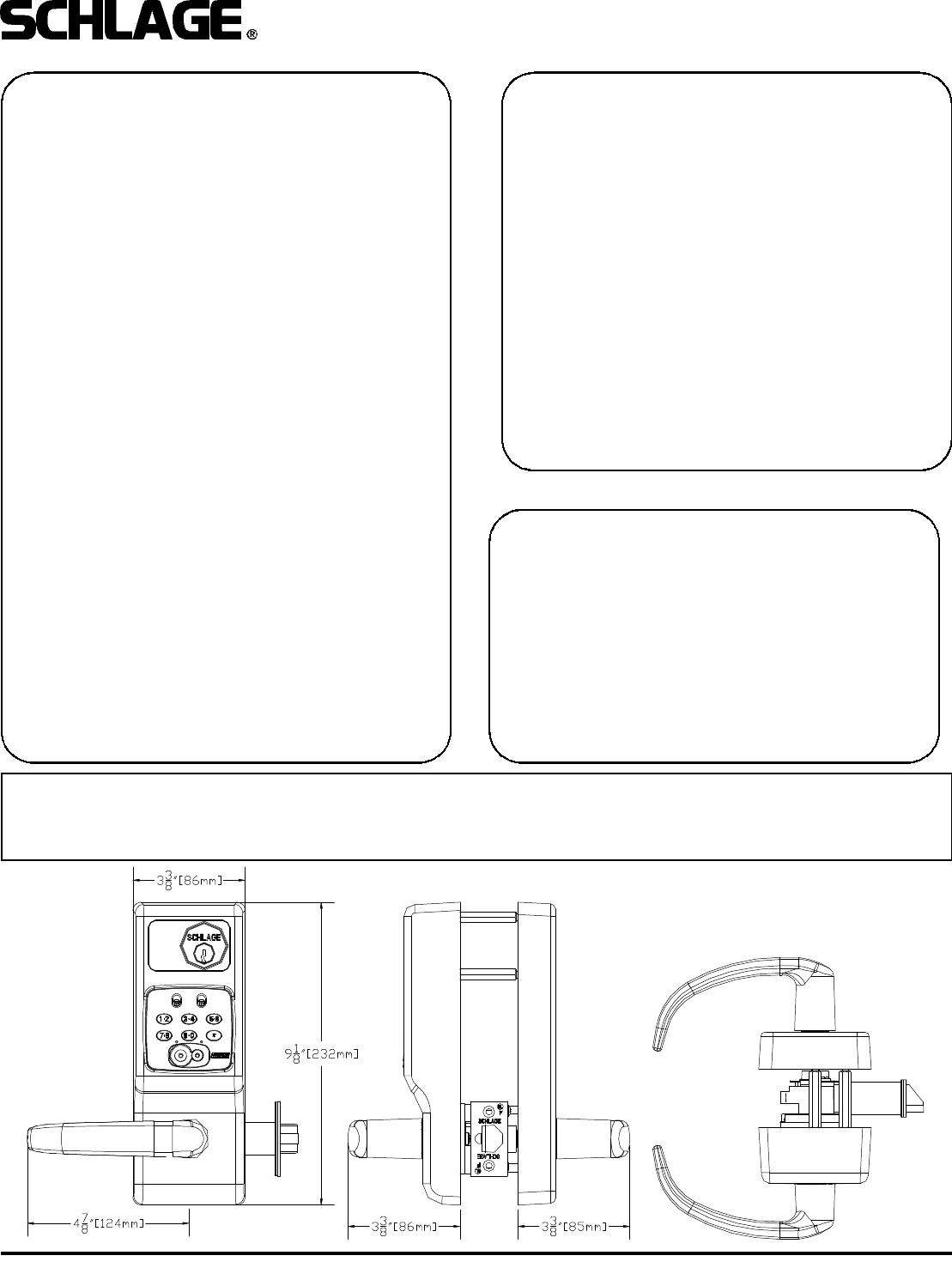
OVERALL DIMENSIONS:
This device complies with part 15 of the FCC rules. Operation is subject to the following two conditions: (1) this device may
not cause harmful interference, and (2) this device must accept any interference received, including any interference that may
cause undesired operation. Changes or modifications not expressly approved by the party responsible for compliance could
void the user’s authority to operate the equipment.