Schlage Electronic Security PROXIF Door Lock User Manual 55005 D
Schlage Electronic Security Door Lock 55005 D
Contents
- 1. 5100 Manual
- 2. 5500 Manual
5500 Manual
Form 55005 Rev. D 12-02-2002
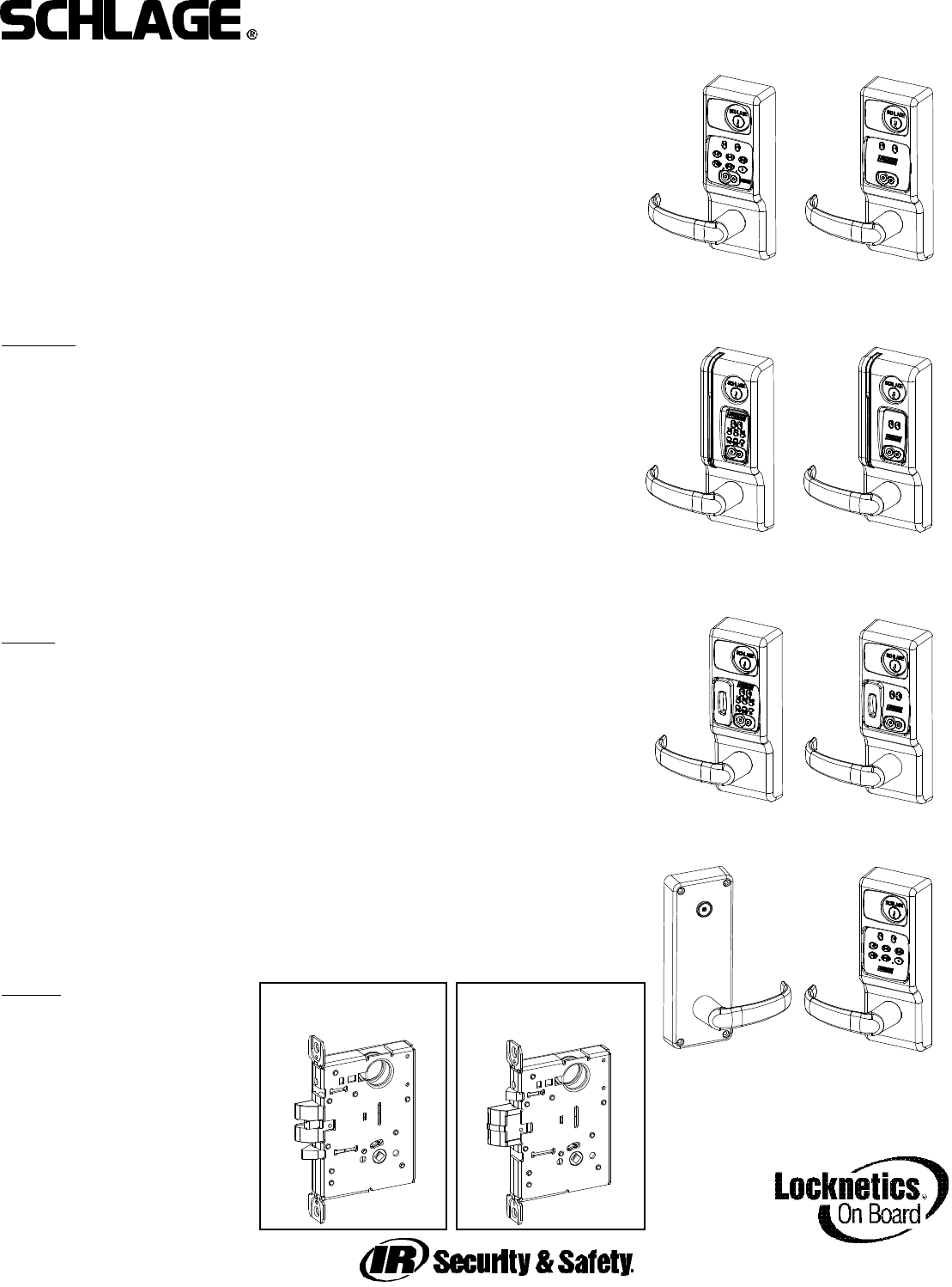
CM5500 COMPUTER MANAGED MORTISE LOCK
INSTALLATION MANUAL
CM5500-KPI CM5500-IBO
CM5500-MGK CM5500-MGI
PRO5500
The 5500 series lock is a stand-alone, microprocessor controlled, electromechanical
locking system. The 5500 employs a heavy-duty mechanical design with fewer moving parts
that a standard mechanical mortise lockset, for ease of installation and high reliability. It is pow-
ered by four, standard AA batteries, providing up to 80,000 activations.
Operationally, the outside lever is normally locked and the inside lever always retracts
the bolt to allow egress. Electronic access control is achieved by entering an”Access
Credential” (magnetic stripe card, code of iButton Key, or Prox fob or card). Electronic access
control capabilities are listed below by model. All models are designed to accommodate an
emergency mechanical key override. Standard features of the CM models include up to 1000
user memory, real time features including time zones and holidays, and audit trail of up to 1000
events. Optional ATK (audit trail - key override) will note any use of the mechanical key on the
audit trail report. Manual and computer programming is supported by all models. The PRO
models are manually programmed to accept up to 100 codes.
Functions:
5590: Office Function (3/4” latch) - has “Lock” and “Unlock” buttons on inside escutcheon.
Function not available on PRO
5596: Storeroom/Classroom Function (3/4” latch) - can be unlocked by “toggle” credential and
relocked again by same. See programming guide for more information (form 57000).
5598: Classroom Function with inside iButton reader - can be toggled unlocked by iButton plus
pin (code). Can be relocked immediately from inside iButton reader in an emergency.
5591: Office Function (1” Autobolt) - has “Lock” and “Unlock” buttons on inside escutcheon.
Function not available on PRO
5594: Storeroom/Classroom Function (1” Autobolt) - can be unlocked by “toggle” credential
and relocked again by same. See programming guide for more information (form 57000).
Function not available on PRO
5593: Dormitory/Privacy Function (1” Autobolt) - Pushing “Privacy On” button on the inside
escutcheon places lock in the “Privacy” mode: a “Lockout” credential or mechanical key is
required to enter. Condition is cleared when the bolt is retracted from the inside or by pushing
the “Privacy Off” button. Function not available on PRO.
Models:
KPI: iButton reader and keypad
IBO: iButton reader only
MGK: Magnetic stripe card reader, iButton reader and keypad
MGI: Magnetic stripe card reader and iButton reader
PXK: HID Prox card reader, iButton reader, and keypad
PXI: HID Prox card reader and iButton reader
PPK: interflex ProxIF Prox card reader, iButton reader, and keypad
PPI: interflex ProxIF Prox card reader and iButton reader
PCK: Casi Rusco Prox card reader, iButton reader, and keypad
PCI: Casi Rusco Prox card reader and iButton reader
PRO: Keypad only - Manual programming only, 100 code memory
Options:
ATK: Audit trail of mechanical
key use (not available on
PRO)
HSS: High security screws on
inside escutcheon
T3: Track 3 card reader (data
must be ABA track 2 for
mat) - MGI/MGK only
KD: Keyed Different, includes
Schlage Everest cylinder
LC: Less Cylinder
5500 MORTISE LOCK
AUTOBOLT
5500 MORTISE LOCK
STANDARD
CM5598
SAFE SCHOOL LOCK
WITH iBUTTON
READER ON INSIDE
CM5500-PXK
CM5500-PPK
CM5500-PCK
CM5500-PXI
CM5500-PPI
CM5500-PCI
Form 55005 Rev. D 12-02-20022
CM5500 COMPUTER MANAGED MORTISE LOCK
INSTALLATION MANUAL
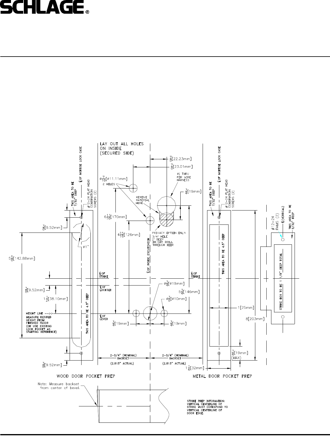
1. PREP DOOR AND FRAME (IF NOT ALREADY DONE):
A. Determine door hand.
B. Mark the horizontal and vertical centerlines for the lock case (on door edge), strike, lever, and inside escutcheon. Note
that the backset is actually 2.813” (or 2 13/16”). This is very important for proper mounting.
C. Place template on inside of door (opposite the side that the keypad/reader will be on). Line up the correct reference lines
on the template with the edge of the door, depending on the hand (see paper template). The centerline on the door should
line up with the vertical centerline of the template. Use the paper template to mark all holes. (Though the paper template is
the preferred way to prep the door, the dimensions below may be used if a paper template is not available.)
D. Drill required holes. Note that all holes are required except the 3/4” hole just below the 1” hole, this is only required if the
lock has the privacy feature (model 5593).
BEFORE YOU BEGIN:
Standard units are shipped from the factory to fit 1-3/4” doors. Verify the door thickness. If the door is not 1-3/4” thick, verify
that the door thickness option was ordered or consult factory.
Form 55005 Rev. D 12-02-20023
CM5500 COMPUTER MANAGED MORTISE LOCK
INSTALLATION MANUAL
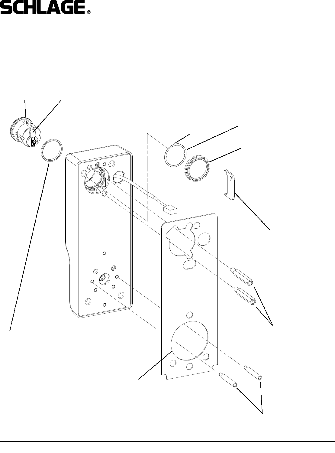
2. INSTALL CYLINDER, GASKET AND STANDOFFS:
A. Install cam onto cylinder. Cam can be either a cloverleaf (shown) or straight, 11/16” design (not shown).
B. Insert standard, 1-1/8” mortise cylinder into outside escutcheon from front (keypad/reader) side with keyway down.
C. Slide lock washer into place with tab on top facing out, as shown below.
D. Using nut tool (provided) tighten nut onto cylinder.
E. Line up nearest notch on nut with tab on lock washer and bend tab into notch using nut tool so nut is secure.
F. Install exterior gasket (if used).
G. Install upper and lower standoffs.
CYLINDER RECOMMENDED CAM:
SCHLAGE EVEREST: P/N B502-948
SCHLAGE CLASSIC: P/N B502-191
NUT TOOL
EXTERIOR GASKET
LOCK WASHER
NUT
STANDOFFS - UPPER
STANDOFFS - LOWER
TAB
NOTE:
BLOCKING RING REQUIRED FOR CYLINDER
LENGTH GREATER THAN 1-1/8”.
THICKNESS = CYLINDER LENGTH -1 1/8”
Form 55005 Rev. D 12-02-20024
CM5500 COMPUTER MANAGED MORTISE LOCK
INSTALLATION MANUAL
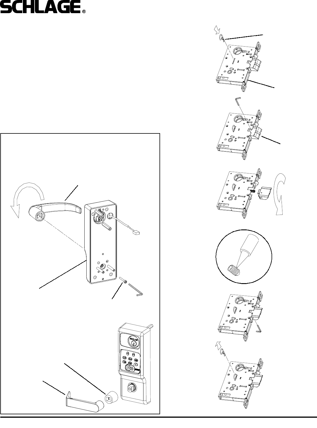
3. CHANGE HAND (IF NECESSARY):
NOTE: The locks are shipped as ordered from factory. If it is
necessary to change the hand of the lock, follow the steps
below:
TO CHANGE HAND OF LOCK CASE:
A. With bolt fully extended, insert change pin (included in the
hardware pack) into hole. (It will snap over a groove on the
main shaft, holding it in place.)
B. Remove set screw in bolt so bolt can be removed.
C. Rotate bolt and reinstall on to shaft. Do not remove spring.
D. Apply thread locking compound to set screw.
Loctite 242 recommended.
E. Install and tighten set screw (from other side, as shown).
F. Remove change pin.
5/32” SOCKET CAP SCREW
LOCTITE 242 RECOMMENDED
OUTSIDE ESCUTCHEON
ADAPTER
LEVER
OUTSIDE HANDLE
CHANGE PIN
LOCK CASE
BOLT
(AUTOBOLT SHOWN)
TO CHANGE HAND OF LEVERS:
A. Loosen 5/32” socket cap screw and remove lever.
B. Rotate handle to opposite position.
C. Apply thread locker to screw. Loctite 242 recommended.
D. Reinstall handle.
E. Repeat for inside escutcheon (not shown).
NOTE:
Some lever designs
require an adapter.
A
B
C
E
D
F
Form 55005 Rev. D 12-02-20025
CM5500 COMPUTER MANAGED MORTISE LOCK
INSTALLATION MANUAL
LOCK CASE
#12 COMBINATION
SCREWS
IF UNIT HAS PRIVACY FEATURE,
FEED WIRE THROUGH CAVITY
AND OUT 3/4” HOLE AS LOCK
CASE IS INSERTED. DO NOT
PINCH WIRES BETWEEN PARTS.
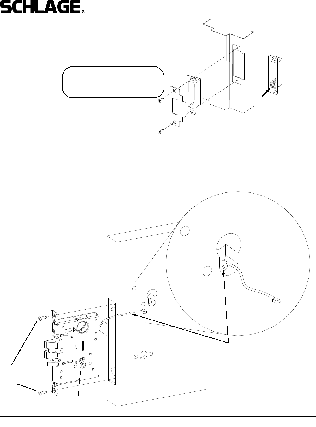
4. INSTALL STRIKE BOX AND STRIKE:
5. INSTALL LOCK CASE:
Install lock case into edge of door. If the lock has the Privacy option (CM5593), feed the wire harness though the 3/4” hole
as shown below. Secure to door with #12-24 combination screws.
IMPORTANT!
Strike included with lock MUST be
used for proper operation of mortise
lockset.
CM5593 (PRIVACY)
MODELS MUST HAVE
STRIKE BOX
INSTALLED WITH POT-
TED MAGNET ON BOT-
TOM AS SHOWN.
Form 55005 Rev. D 12-02-20026
CM5500 COMPUTER MANAGED MORTISE LOCK
INSTALLATION MANUAL
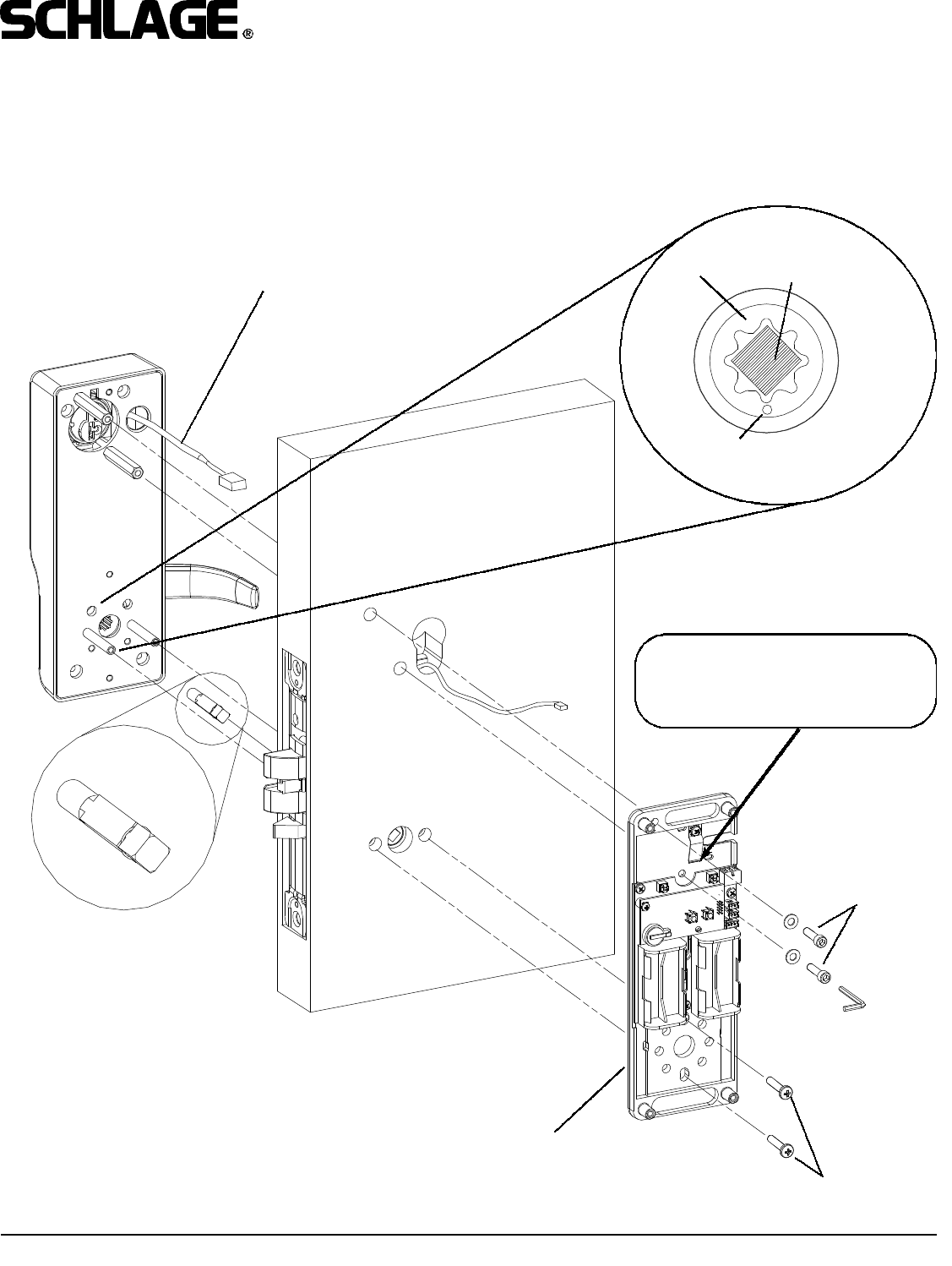
6. INSTALL OUTSIDE SPINDLE, OUTSIDE ESCUTCHEON AND BASE PLATE ASSEMBLY:
Install base plate assembly onto inside of door. Use socket cap screws with washers on top standoffs and phillips head
screws on retractor assembly (bottom). Note that the cam on the outside escutcheon must be positioned with the dot at the
6 O’Clock position and inside spindle must be inserted as shown in details.
CAUTION!
If any fasteners such, as washers,
fall behind the PC board, remove
them prior to installing batteries.
INSIDE SPINDLE MUST BE
INSERTED AS SHOWN
SOCKET CAP
SCREW, WASHERS
BASE PLATE ASSEMBLY
PASS WIRING HARNESS THROUGH 1”
HOLE IN DOOR
PHILLIPS HEAD
SCREWS
DOT - FACES
DOWN
OUTSIDE
SPINDLE
POSITION
CAM
DETAIL
Form 55005 Rev. D 12-02-20027
CM5500 COMPUTER MANAGED MORTISE LOCK
INSTALLATION MANUAL
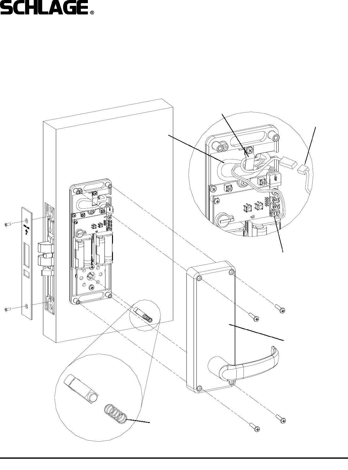
ASSEMBLE SPRING ONTO
INSIDE SPINDLE AND INSERT
INTO CAM IN LOCKSET AS
SHOWN
INSIDE ESCUTCHEON
PHILLIPS SCREWS
(STANDARD) OR
NO.6 SPANNER
SCREWS
(HSS OPTION - NOT
SHOWN)
7. INSTALL INSIDE SPINDLE, BATTERIES, AND INSIDE ESCUTCHEON:
NOTE: The lock is shipped with four AA alkaline batteries. Always use new, high quality alkaline batteries.
A. Plug wiring harness into PC board.
B. Tuck wiring harness under retaining clip as shown in detail A, below. Not all wires shown will be present on all models.
C. Install four AA batteries. Note polarity indication on battery holders.
D. Assemble spring onto inside spindle as shown. install spindle into cam in lockset. Note that the flat side faces away from
the door (See detail B).
E. Install inside escutcheon, making sure that the inside spindle engages the lever cam.
F. Test operation of inside lever to make sure that latch retracts fully.
DETAIL B
WIRE HARNESS
RETAINING CLIP
DETAIL A INSIDE
IBUTTON WIRE
HARNESS
WIRE HARNESS
(PRIVACY ONLY)
WIRE HARNESS
(STANDARD)
Form 55005 Rev. D 12-02-20028
CM5500 COMPUTER MANAGED MORTISE LOCK
INSTALLATION MANUAL
OPERATIONAL TEST:
1. Push down and up on inside lever: latch should
retract.
2. Push down and up on outside lever. Lever should
be disengaged from retractor and door should not
unlock.
3. Insert mechanical key into cylinder and turn coun-
terclockwise until it stops (about 1/2 turn). Push down
and up on the outside lever. The latch should retract.
(On units with ATK option you should see the green
LED flash on the keypad/reader when the key is
turned.)
4. If the unit has a keypad, enter the factory default
access code:
1 - 3 - 5 - 7 - 9
as soon as “9” is pressed you should hear a quiet
“whir” and the green LED should flash green for about
10 seconds. During this time, push the handle down.
The latch should retract. After the green LED stops
flashing you should hear another quiet “whir” and the
lock should relock. Test the handle again to verify that
it is locked.
Note: Refer to the Programming Guide for information
on entering iButton keys or cards to test them. Note
that some literature may refer to I-buttons as “TEKs”
or “TouchEntry Keys”.
TROUBLE SHOOTING:
PROBLEM: POSSIBLE CAUSE:
Inside lever doesn’t
retract latch: Inside spindle not installed
Mechanical key not
working: Wrong cam installed or
cam installed in wrong
position. Outside spindle
not installed properly.
Cylinder upside down.
No response from key-
pad/reader: Wiring harness not plugged
in/Batteries not installed
properly. Electronics prob-
lem (consult tech. support)
PROGRAMMING:
Please refer to the programming guide, shipped with
the product, for instructions on manual programming
and creating master programming credentials. If com-
puter programming is required, please refer to the
documentation and help files included with the soft-
ware for more information.
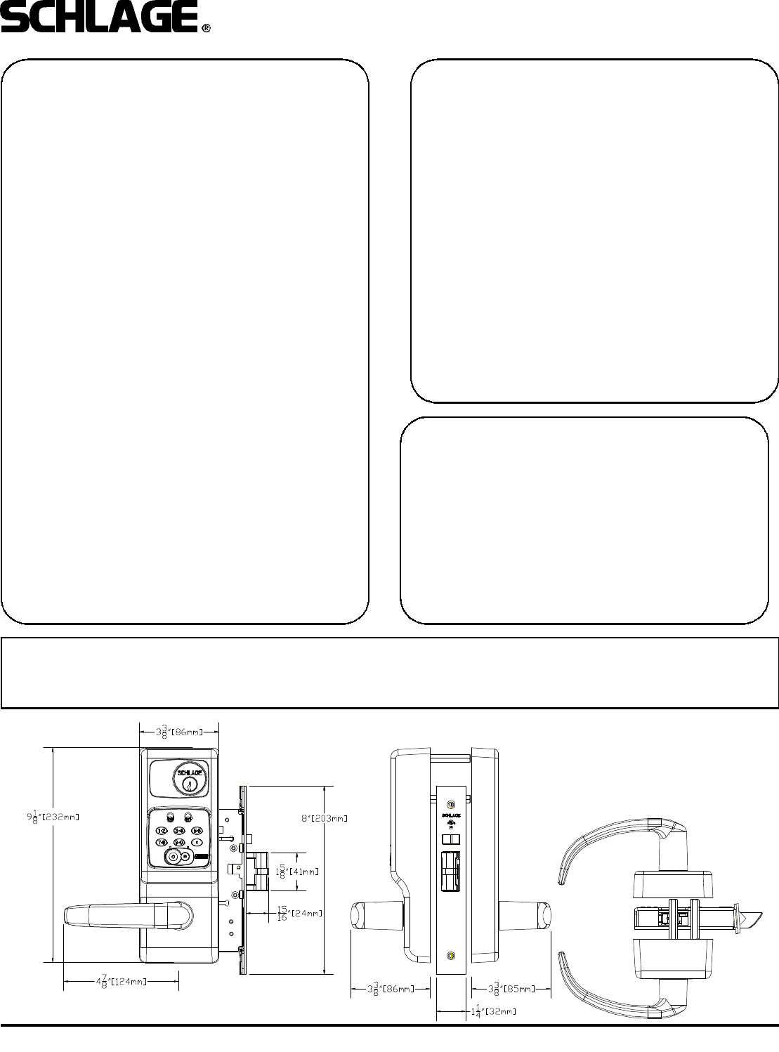
OVERALL DIMENSIONS:
This device complies with part 15 of the FCC rules. Operation is subject to the following two conditions: (1) this device may
not cause harmful interference, and (2) this device must accept any interference received, including any interference that may
cause undesired operation. Changes or modifications not expressly approved by the party responsible for compliance could
void the user’s authority to operate the equipment.