Schlage Electronic Security VIPFP Door Lock User Manual 57032 A
Schlage Electronic Security Door Lock 57032 A
UserManual.wiki
>
Schlage Electronic Security
>
VIPFP User Manual
>
Manual 5100
Contents
1.
Manual 5100
2.
Manual 5500
3.
Manual 993
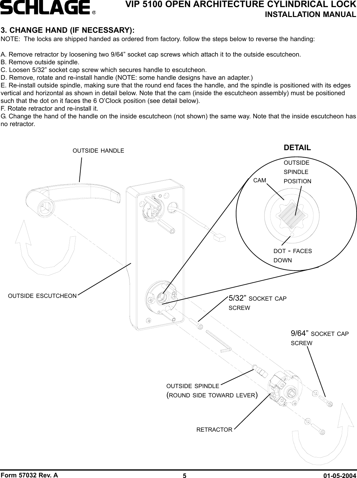
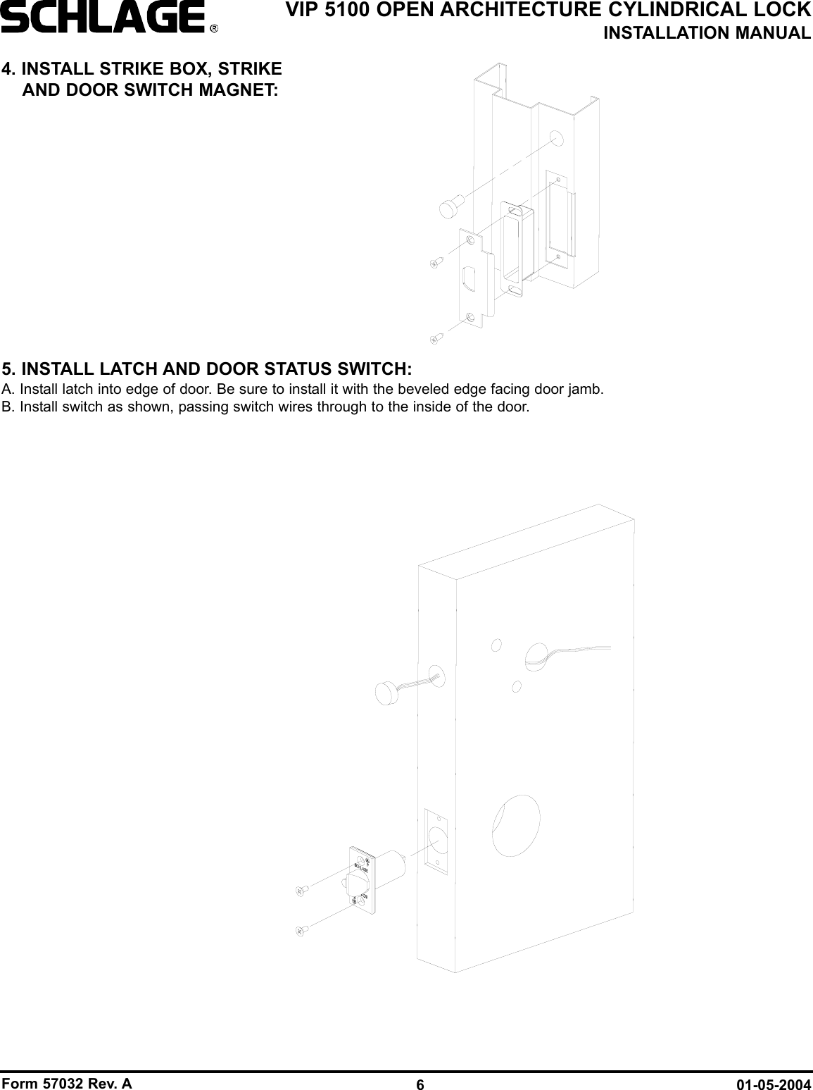
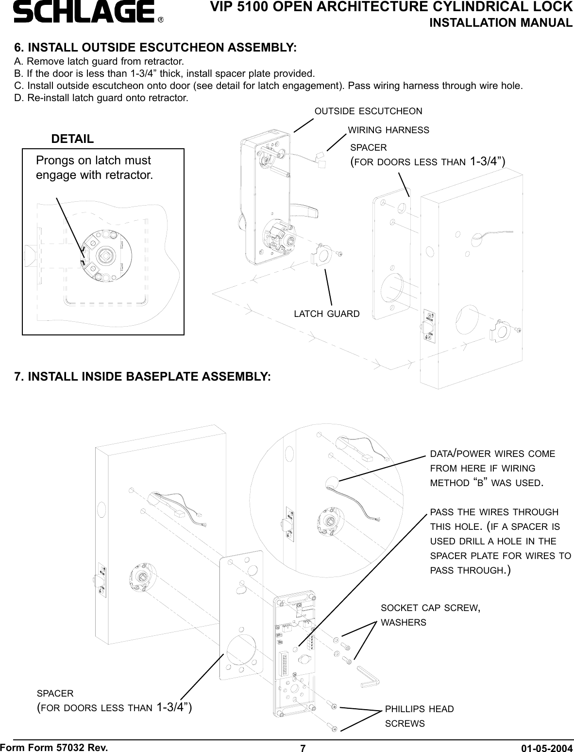
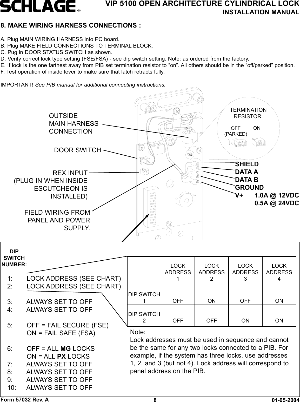
Manual 5100
Navigation menu
Upload a User Manual
Namespaces
Wiki Guide
HTML
PDF
Info
Views
User Manual
Discussion / Help
Navigation