Schlage Electronic Security VIPFP Door Lock User Manual 57033 A
Schlage Electronic Security Door Lock 57033 A
Contents
- 1. Manual 5100
- 2. Manual 5500
- 3. Manual 993
Manual 5500
Form 57033 Rev. A 01-05-2004
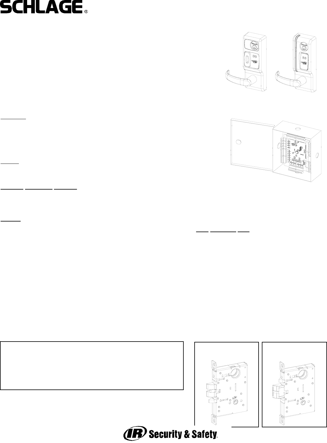
VIP 5500 OPEN ARCHITECTURE MORTISE LOCK
INSTALLATION MANUAL
5500 MORTISE LOCK
AUTOBOLT
5500 MORTISE LOCK
STANDARD
The VIP 5500 series lock is a microprocessor controlled, electromechanical locking system.
It is an open architecture product designed to interface with 3rd party panels encompassing
all the features of the lock, reader, door status and egress (rex/request to exit) indication in
one fire-rated piece of hardware. The 5100 employs a heavy-duty mechanical design tested
and complying with ANSI/BHMA grade 1 standards for performance and reliability. It is pow-
ered by 12 or 24 volts DC with only four wires required - two for power and two for commu-
nications. The lock communicates with a PIB (panel interface board) which communicates
with the panel as if it were separate components of an access control system.
Operationally, the outside lever is normally locked and the inside lever always retracts the
bolt to allow egress. Electronic access control is achieved by entering an”Access Credential”
(magnetic stripe card or Prox fob or card). The panel controls the lock through the PIB.
Please refer to all instruction manuals involved in the installation before you begin.
Functions:
VIP 5594-FSA: (1” AutoBolt) - Fail Safe (unlocked)
VIP 5594-FSE: (1” AutoBolt) - Fail Secure (locked)
VIP 5596-FSA: (3/4” latch) - Fail Safe (unlocked)
VIP 5596-FSE: (3/4” latch) - Fail Secure (locked)
Models:
MG: Magnetic stripe card reader
PX: HID Prox card reader
Standard Monitoring Switches:
DSM: Provides door status via data link to panel interface
KSM: Provides mechanical key use events via data link to panel interface
REX: Provides indication of inside lever use for request to exit input via data link
to panel interface
Options:
T3: Track 3 card reader (data must be ABA track 2 format) - MG only
EXT: exterior use option - MG only (PX model has this standard)
KD: Keyed Different, includes Schlage Everest cylinder
KA: Keyed Alike, includes Schlage Everest cylinder
LC: Less Cylinder
SLB: 2-3/4” backset, 1/2” latch bolt
OLB: 2-3/8” backset, 1/2” latch bolt
ELB: 2-3/4” backset, 3/4” latch bolt
BEFORE YOU BEGIN:
Standard units are shipped from the factory to fit 1-3/4” doors. Verify the door thickness. If the door is not 1-3/4” thick, verify
that the door thickness option was ordered or consult factory.
PRE-INSTALLATION CHECK:
AN OPEN ARCHITECTURE SYSTEM REQUIRES AT LEAST THREE COMPONENTS - A PANEL INTERFACE BOARD (PIB), AN
ACCESS CONTROL PANEL (BY OTHERS) TO WHICH THE PIB IS CONNECTED AND THE VIP LOCK. SEE DOCUMENTATION FOR
THE ACCESS CONTROL PANEL/SOFTWARE THIS LOCK WILL BE USED WITH FOR ANY PRE-INSTALLATION TESTING
REQUIREMENTS AND REMEDIES. REFER TO THE WIRING INFORMATION INCLUDED WITH THE PIB FOR MORE INFORMATION.
PIB
PX MG
Door Thickness Kits:
Available in 1/8” increments from 1-3/8” to 2-1/2”
This device complies with part 15 of the FCC rules. Operation is sub-
ject to the following two conditions: (1) this device may not cause
harmful interference, and (2) this device must accept any interference
received, including any interference that may cause undesired opera-
tion. Changes or modifications not expressly approved by the party
responsible for compliance could void the user’s authority to operate
the equipment.
Form 57033 Rev. A 01-05-20042
VIP 5500 OPEN ARCHITECTURE MORTISE LOCK
INSTALLATION MANUAL
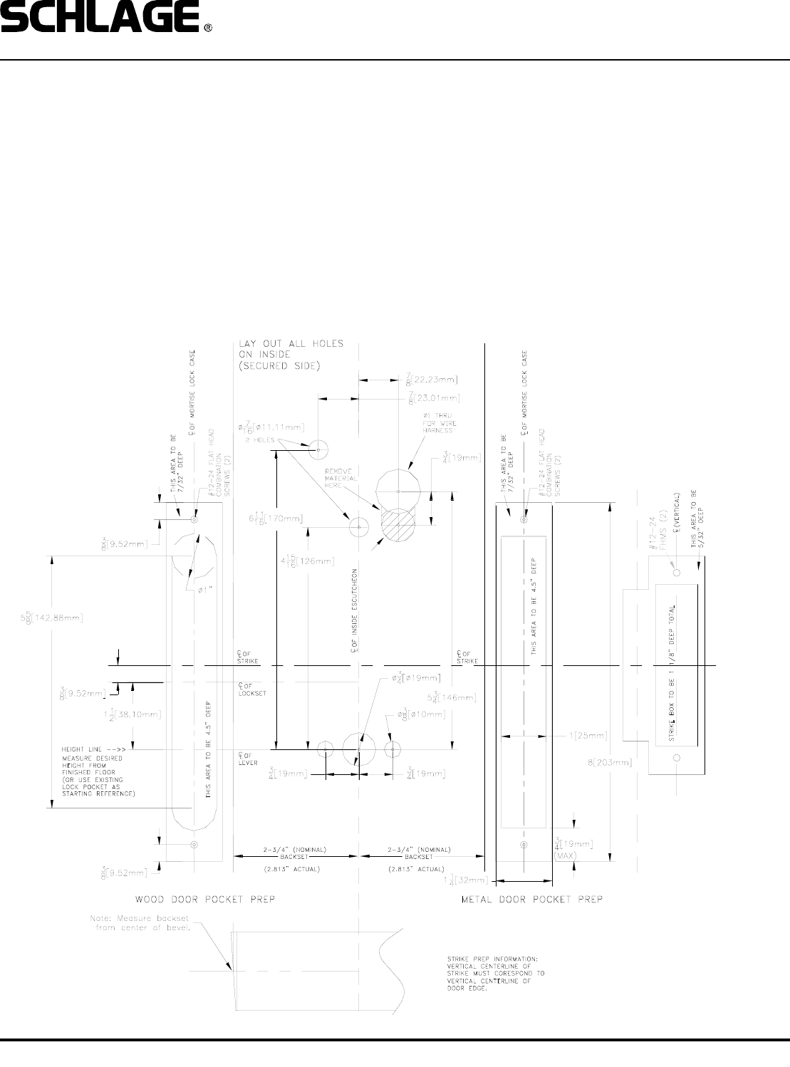
1. PREP DOOR AND FRAME (IF NOT ALREADY DONE):
A. Determine door hand.
B. Mark the horizontal and vertical centerlines for the lock case (on door edge), strike, lever, and inside escutcheon. Note
that the backset is actually 2.813” (or 2 13/16”). This is very important for proper mounting.
C. Place template on inside of door (opposite the side that the keypad/reader will be on). Line up the correct reference lines
on the template with the edge of the door, depending on the hand (see paper template). The centerline on the door should
line up with the vertical centerline of the template. Use the paper template to mark all holes. (Though the paper template is
the preferred way to prep the door, the dimensions below may be used if a paper template is not available.)
D. Drill required holes. Note that all holes are required except the 3/4” hole just below the 1” hole, this is only required if the
lock has the DSM (door status) switch.
FOR DOOR SWITCH
WIRES:
3/4” HOLE 1” DEEP
DO NOT DRILL THRU
DOOR!
Form 57033 Rev. A 01-05-20043
VIP 5500 OPEN ARCHITECTURE MORTISE LOCK
INSTALLATION MANUAL
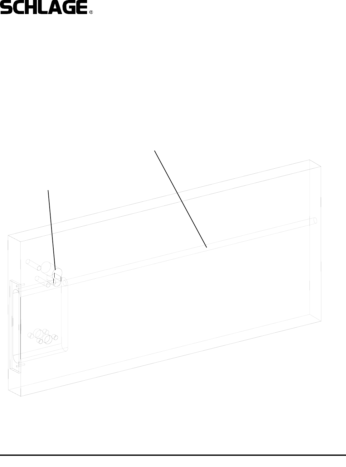
Suggested wire raceway:
1/2” hole into top of mortise pocket.
Wiring will exit toward inside
through this hole.
FSE & FSA HARD WIRED MODELS REQUIRE WIRING TO BE RUN
TO THE MORTISE POCKET FROM THE HINGE SIDE. BELOW IS A
SUGGESTED WAY TO DO THIS. A DOOR CORD OR ELECTRIC
HINGE OR TRANSFER DEVICE MUST BE USED TO GET WIRING
FROM THE FRAME TO THE DOOR. NOTE THAT WHEN USING AN
ELECTRIC HINGE IT IS RECOMMENDED THAT THE POWER
WIRES BE DOUBLED OR TRIPLED UP (ON BOTH THE POSITIVE
AND GROUND LEGS) TO AVOID SIGNIFICANT VOLTAGE DROP
THROUGH THE THIN WIRES IN THE HINGE.
Form 57033 Rev. A 01-05-20044
VIP 5500 OPEN ARCHITECTURE MORTISE LOCK
INSTALLATION MANUAL
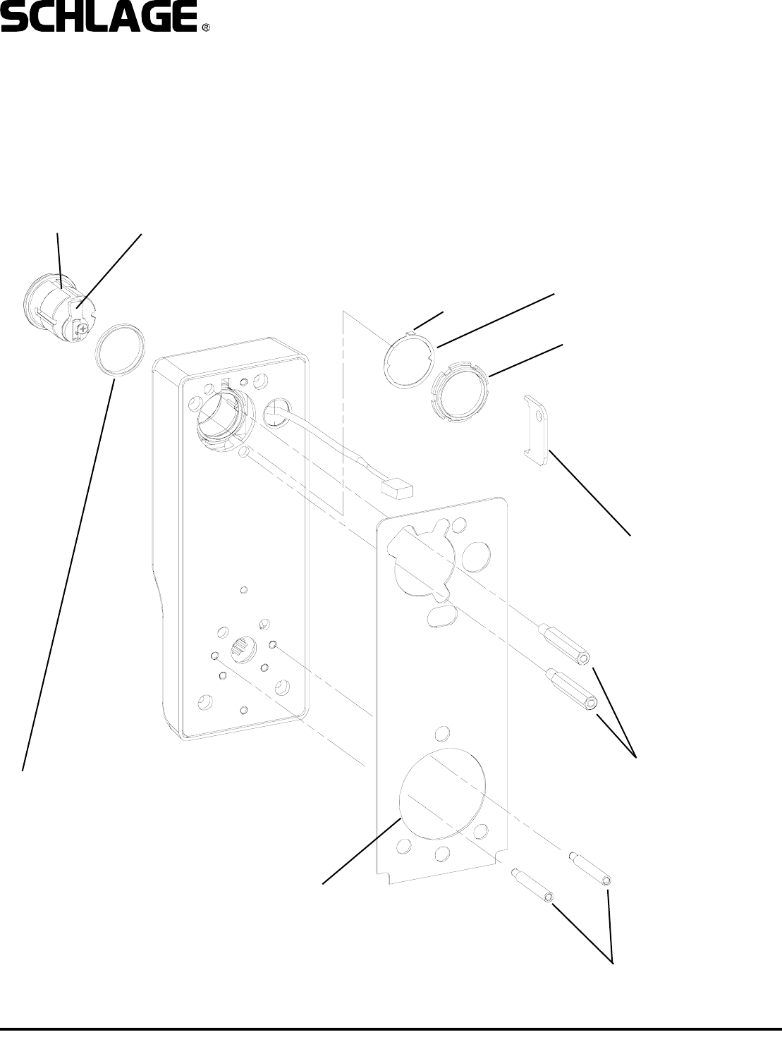
2. INSTALL CYLINDER, GASKET AND STANDOFFS:
A. Install cam onto cylinder. Cam can be either a cloverleaf (not shown) or straight, 11/16” design (shown).
B. Insert standard, 1-1/8” mortise cylinder into outside escutcheon from front (keypad/reader) side with keyway down.
C. Slide lock washer into place with tab on top facing out, as shown below.
D. Using nut tool (provided) tighten nut onto cylinder.
E. Line up nearest notch on nut with tab on lock washer and bend tab into notch using nut tool so nut is secure.
F. Install exterior gasket (if used).
G. Install upper and lower standoffs.
CYLINDER RECOMMENDED CAM:
SCHLAGE EVEREST: P/N B502-948
SCHLAGE CLASSIC: P/N B502-191
NUT TOOL
EXTERIOR GASKET
LOCK WASHER
NUT
STANDOFFS - UPPER
STANDOFFS - LOWER
TAB
NOTE:
BLOCKING RING REQUIRED FOR CYLINDER
LENGTH GREATER THAN 1-1/8”.
THICKNESS = CYLINDER LENGTH -1 1/8”
Form 57033 Rev. A 01-05-20045
VIP 5500 OPEN ARCHITECTURE MORTISE LOCK
INSTALLATION MANUAL
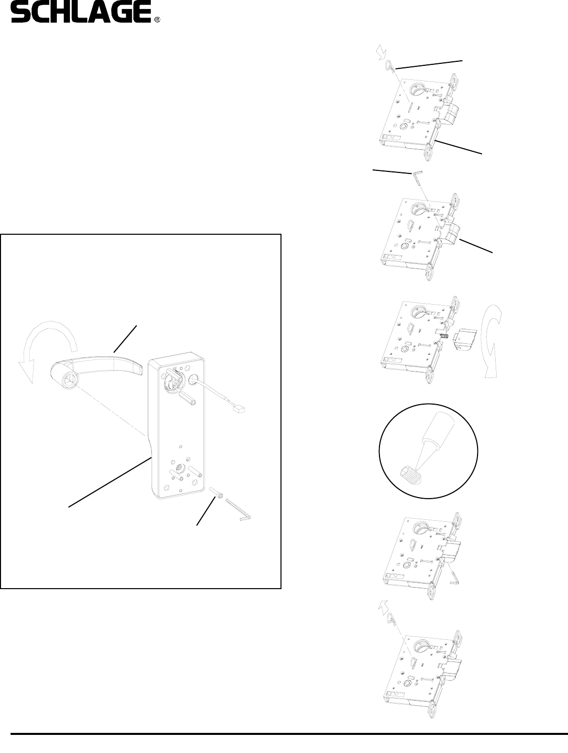
3. CHANGE HAND (IF NECESSARY):
NOTE: The locks are shipped as ordered from factory. Follow
the steps below to reverse handing:
TO CHANGE HAND OF LOCK CASE:
A. With bolt fully extended, insert change pin (included in the
hardware pack) into hole. (It will snap over a groove on the
main shaft, holding it in place.)
B. Remove set screw in bolt so bolt can be removed.
C. Rotate bolt and reinstall on to shaft. Do not remove spring.
D. Apply thread locking compound to set screw.
(Loctite 242 recommended)
E. Install and tighten set screw (from other side, as shown).
F. Remove change pin.
5/32” SOCKET CAP SCREW
LOCTITE 242 RECOMMENDED
OUTSIDE ESCUTCHEON
OUTSIDE HANDLE
CHANGE PIN
LOCK CASE
5/64” HEX
WRENCH
BOLT
(AUTOBOLT SHOWN)
TO CHANGE HAND OF LEVERS:
A. Loosen 5/32” socket cap screw and remove lever.
B. Rotate handle to opposite position.
C. Apply thread locker to screw. (Loctite 242 recommended)
D. Reinstall handle.
E. Repeat for inside escutcheon (not shown).
A
B
C
E
D
F
Form 57033 Rev. A 01-05-20046
VIP 5500 OPEN ARCHITECTURE MORTISE LOCK
INSTALLATION MANUAL
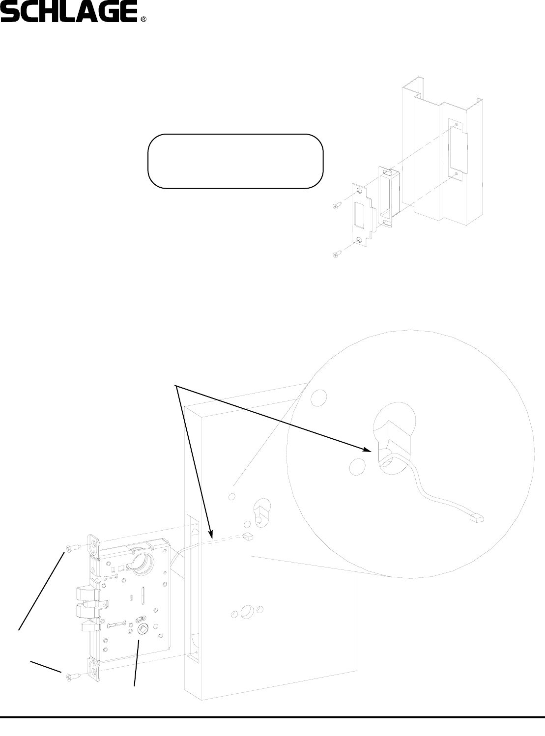
LOCK CASE
#12 COMBINATION
SCREWS
FOR PROPER MONITORING OF DOOR
STATUS, FEED WIRE THROUGH WIRE
HOLE TOWARD INSIDE OF DOOR AS
SHOWN.
4. INSTALL STRIKE BOX AND STRIKE:
5. INSTALL LOCK CASE:
Install lock case into edge of door. If the lock has the DSM switch, feed the wire harness though the 3/4” hole as shown
below. Secure to door with #12-24 combination screws.
IMPORTANT!
Strike included with lock MUST be
used for proper operation of mortise
lockset.
Form 57033 Rev. A 01-05-20047
VIP 5500 OPEN ARCHITECTURE MORTISE LOCK
INSTALLATION MANUAL
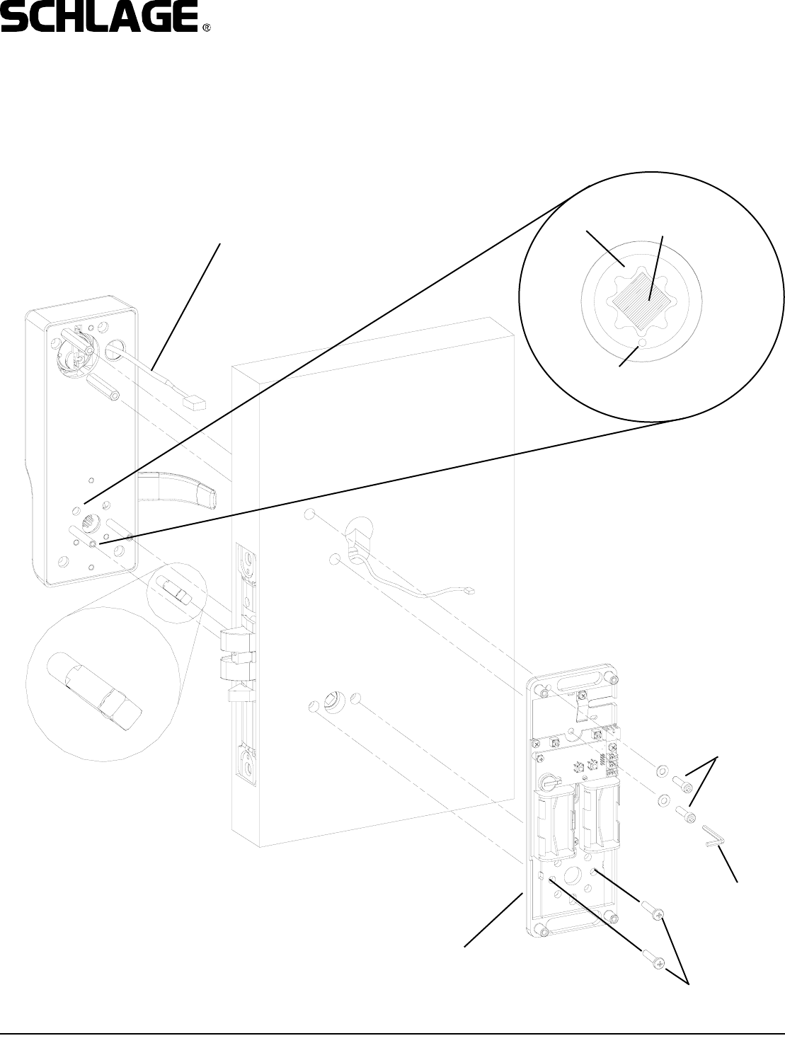
7. INSTALL OUTSIDE SPINDLE, OUTSIDE ESCUTCHEON AND BASE PLATE ASSEMBLY:
Install outside escutcheon and spindle then install base plate assembly onto inside of door. Use socket cap screws with
washers on top standoffs and phillips head screws on lower standoffs. Note that the cam on the outside escutcheon must
be positioned with the dot at the 6 o’Clock position and outside spindle must be inserted as shown in details.
NOTE: Battery Powered inside baseplate shown.
OUTSIDE SPINDLE MUST BE
INSERTED AS SHOWN
SOCKET CAP
SCREW, WASHERS
5/32” HEX
WRENCH
BASE PLATE ASSEMBLY
PASS WIRING HARNESS THROUGH 1”
HOLE IN DOOR
PHILLIPS HEAD
SCREWS
DOT - FACES
DOWN
OUTSIDE
SPINDLE
POSITION
CAM
DETAIL
IMPORTANT!
DO NOT OVERTIGHTEN
FASTENERS OR DOOR
WILL COMPRESS.
Form 57033 Rev. A 01-05-20048
VIP 5500 OPEN ARCHITECTURE MORTISE LOCK
INSTALLATION MANUAL
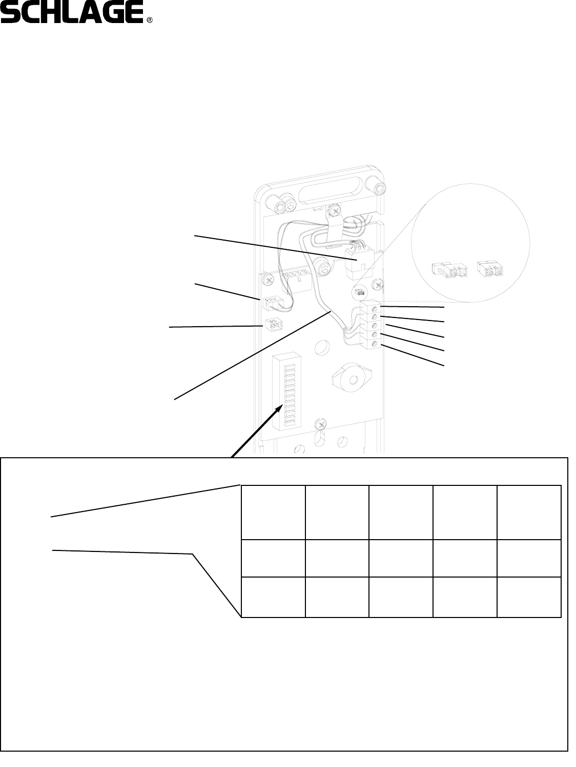
FIELD WIRING FROM
PANEL AND POWER
SUPPLY.
DOOR SWITCH
REX INPUT
(PLUG IN WHEN INSIDE
ESCUTCHEON IS
INSTALLED)
8. MAKE WIRING HARNESS CONNECTIONS :
A. Plug MAIN WIRING HARNESS into PC board.
B. Plug MAKE FIELD CONNECTIONS TO TERMINAL BLOCK.
C. Pug in DOOR STATUS SWITCH as shown.
D. Verify correct lock type setting (FSE/FSA) - see dip switch setting. Note: as ordered from the factory.
E. If lock is the one farthest away from PIB set termination resistor to “on”. All others should be in the “off/parked” position.
F. Test operation of inside lever to make sure that latch retracts fully.
IMPORTANT! See PIB manual for additional connecting instructions.
SHIELD
DATA A
DATA B
GROUND
V+ 1.0A @ 12VDC
0.5A @ 24VDC
OUTSIDE
MAIN HARNESS
CONNECTION OFF
(PARKED)
ON
TERMINATION
RESISTOR:
1: LOCK ADDRESS (SEE CHART)
2: LOCK ADDRESS (SEE CHART)
3: ALWAYS SET TO OFF
4: ALWAYS SET TO OFF
5: OFF = FAIL SECURE (FSE)
ON = FAIL SAFE (FSA)
6: OFF = ALL MG LOCKS
ON = ALL PX LOCKS
7: ALWAYS SET TO OFF
8: ALWAYS SET TO OFF
9: ALWAYS SET TO OFF
10: ALWAYS SET TO OFF
LOCK
ADDRESS
1
LOCK
ADDRESS
2
LOCK
ADDRESS
3
LOCK
ADDRESS
4
DIP SWITCH
1OFF ON OFF ON
DIP SWITCH
2 OFF OFF ON ON
DIP
SWITCH
NUMBER:
Note:
Lock addresses must be used in sequence and cannot
be the same for any two locks connected to a PIB. For
example, if the system has three locks, use addresses
1, 2, and 3 (but not 4). Lock address will correspond to
panel address on the PIB.

Form 57033 Rev. A 01-05-20049
VIP 5500 OPEN ARCHITECTURE MORTISE LOCK
INSTALLATION MANUAL
ASSEMBLE SPRING ONTO
INSIDE SPINDLE AND INSERT
INTO CAM IN LOCKSET AS
SHOWN
INSTALL ARMOR
FRONT. SHIM LOCK
CASE IF NECESSARY
TO CENTER IT IN THE
POCKET.
INSIDE ESCUTCHEON
PHILLIPS SCREWS
(STANDARD) OR
NO.8 SPANNER
SCREWS
(HSS OPTION - NOT
SHOWN)
9. INSTALL INSIDE SPINDLE, BATTERIES, AND INSIDE ESCUTCHEON:
A. Assemble spring onto inside spindle as shown. install spindle into cam in lockset. Note that the flat side faces away from
the door (See detail).
B. Install inside escutcheon, making sure that the inside spindle engages the lever cam. While installing, plug in REX switch
connector.
C. Test operation of inside lever to make sure that latch retracts fully.
D. Install armor front. (Center lock case using shims if necessary.)
DETAIL
PLUG IN REX SWITCH WHEN
INSTALLING INSIDE
ESCUTCHEON ASSEMBLY