Schlage Electronic Security VIPFP Door Lock User Manual 61997 A
Schlage Electronic Security Door Lock 61997 A
Contents
- 1. Manual 5100
- 2. Manual 5500
- 3. Manual 993
Manual 993
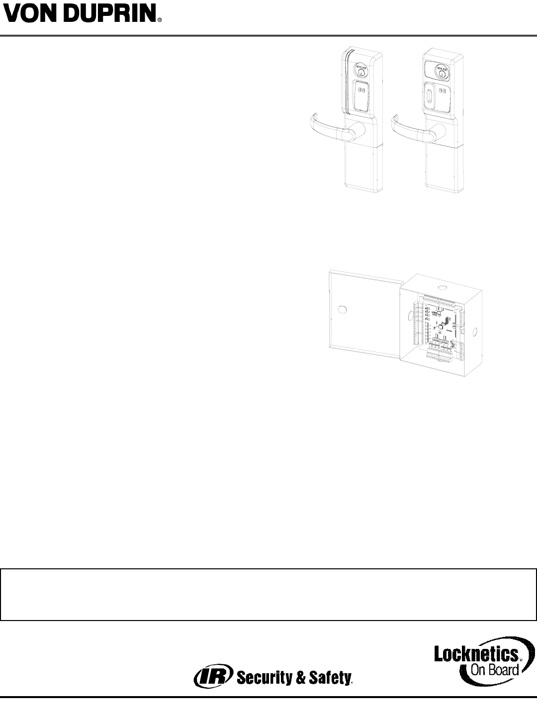
The VIP993 series lock is a microprocessor controlled,
electromechanical locking system which bolts on to new
or existing Von Duprin 98 & 99 rim and vertical rod exit
devices. It is an open architecture product designed to
interface with 3rd party access control panels encom-
passing all the features of the lock, reader, door status
and egress (rex/request to exit) indication in one piece
of hardware. It is powered by 12 or 24 volts DC with
only four wires required to the door - two for power and
two for communications. For door status indication a
door switch (included) must be installed. For request to
exit (REX) the Von Duprin exit device must be equipped
with the exit indication switch (order a RX-LC98/99 exit
device or Von Duprin P/N S1-LC for an aftermarket application)
and a pair of wires (included) must be run from the switch
to the VIP993. The lock communicates with a PIB (panel
interface board) which communicates with the panel as if it
were separate components of an access control system.
Operationally, the outside lever is normally locked the exit
device allows free egress. Electronic access control is
achieved by entering an”Access Credential” (magnetic
stripe card or Prox fob or card). The panel controls the lock
through the PIB.
Compatible Von Duprin exit device
models include:
98/99
9827/9927
9847/8847
9848/9948
9857/9957
Form 61997 Rev. A 01-05-20041
VIP993 OPEN ARCHITECTURE TRIM
HARD-WIRED INSTALLATION MANUAL
MG-FSA
MG-FSE
PX-FSA
PX-FSE
PIB
This device complies with part 15 of the FCC rules. Operation is subject to the following two conditions: (1) this device
may not cause harmful interference, and (2) this device must accept any interference received, including any interference
that may cause undesired operation. Changes or modifications not expressly approved by the party responsible for com-
pliance could void the user’s authority to operate the equipment.
- PAGE 2 -
Form 61997 Rev. A
VIP 993 OPEN ARCHITECTURE TRIM
Installation Instructions - HARDWIRED
01-05-2004
TWO
CENTER
SCREWS
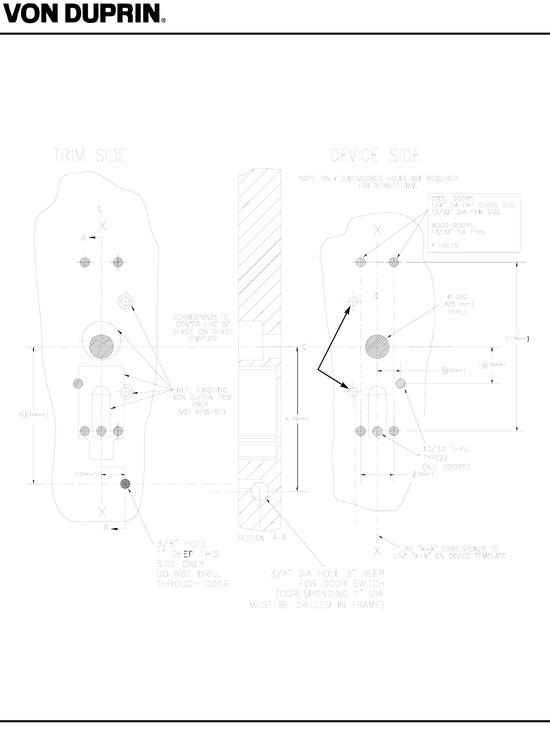
1. PREP DOOR: Remove exit bar and modify door prep with additional holes required for trim per
template below (or use paper template provided).
DOOR SHOWN PREPPED
FOR VON DUPRIN TRIM.
ACTUAL EXISTING DOOR
PREP (IF ANY) MAY VARY.
- PAGE 3 -
Form 61997 Rev. A
VIP993 OPEN ARCHITECTURE TRIM
Installation Instructions - HARDWIRED
01-05-2004
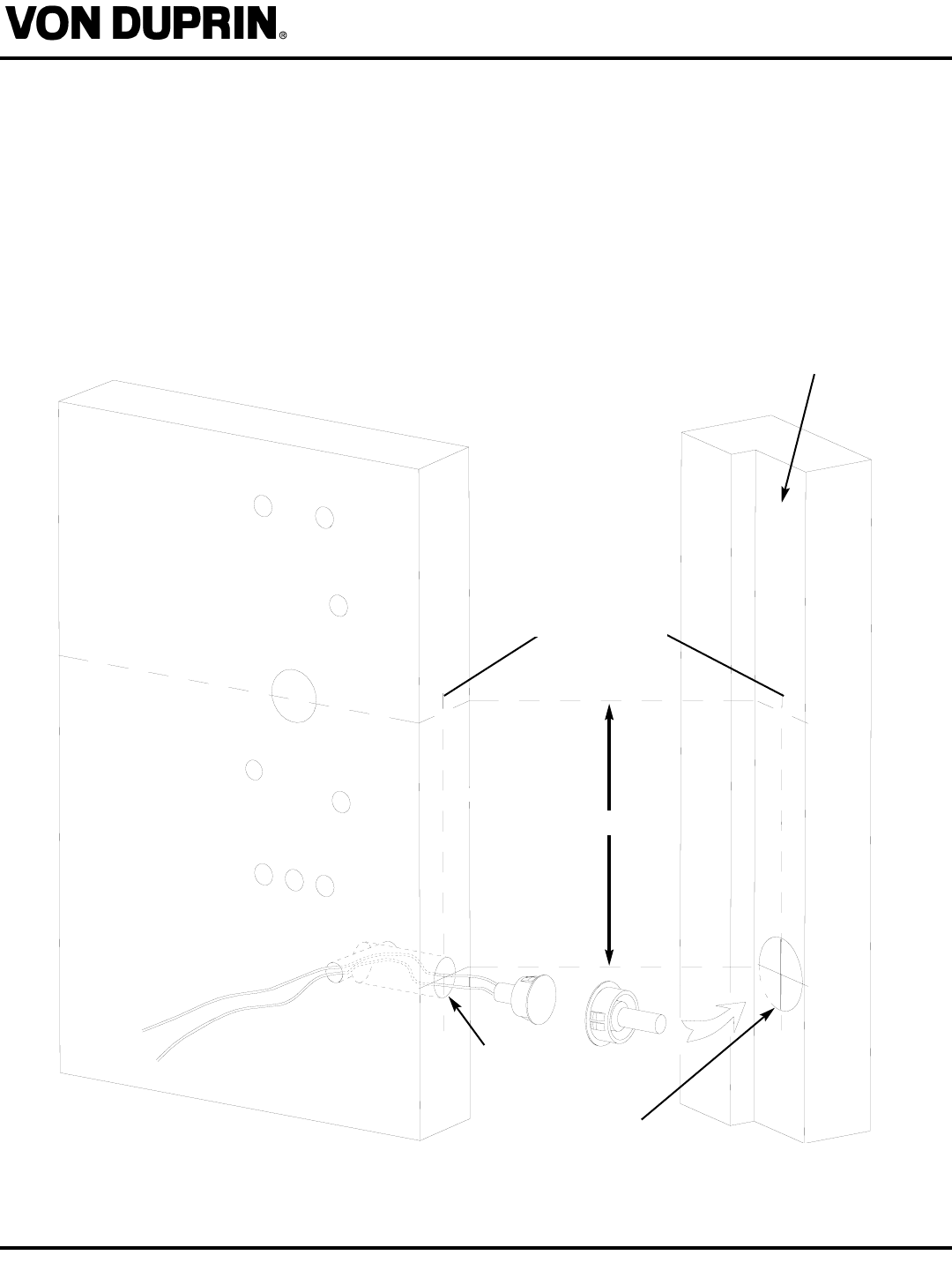
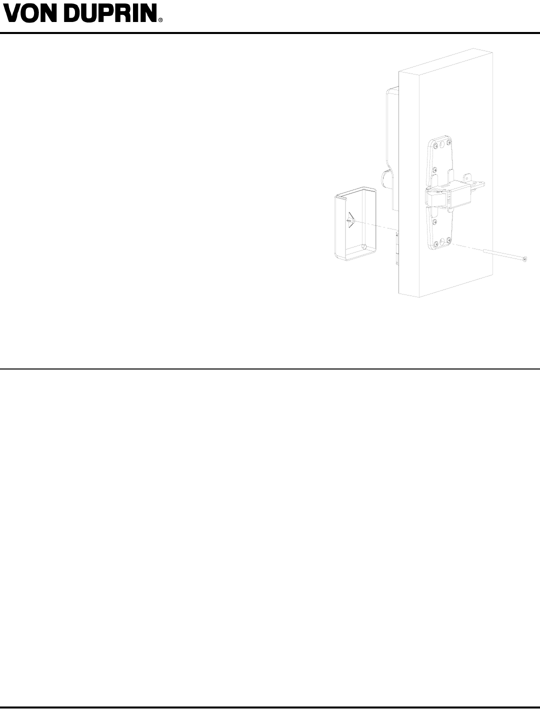
2. PREPARE FOR AND INSTALL DOOR STATUS SWITCH & MAGNET: Measure down 6” from
the horizontal centerline of the exit device on both the door and the frame. Centered on the door
edge drill a 3/4” hole 2” deep to intersect the 3/8” hole on the trim side. On the frame drill a 1” hole
2” deep directly opposite the 3/4” hole on the door. Install the magnet in to the frame. Install the
switch into the door, passing the wires through the hole in the face of the trim side as shown.
NOTE: This door switch location has been determined to be the best for most door and frame con-
ditions. It is possible that certain existing door and frame conditions may require the switch to be
located in a different position. Door switch wires must still exit the door face through the hole as
shown.
6”
3/4” HOLE
2” DEEP
FOR
SWITCH 1” HOLE
2” DEEP
FOR
MAGNET
DOOR
CENTERLINE
TRIM SIDE OF
DOOR
FRAME RABBET
- PAGE 4 -
FORM 60993 Rev. A
VIP 993 OPEN ARCHITECTURE TRIM
Installation Instructions - HARDWIRED
01-05-2004
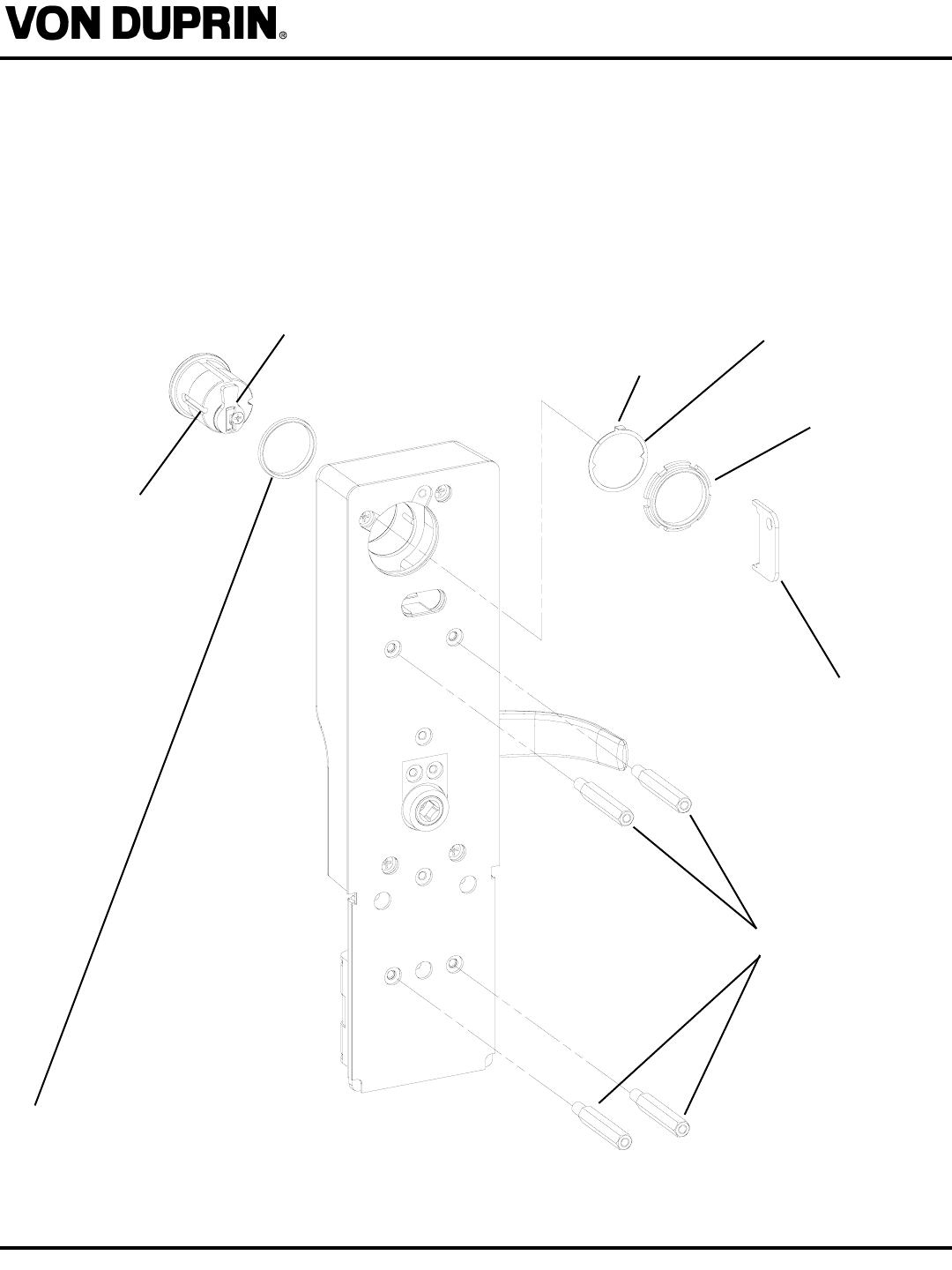
3. INSTALL CYLINDER, GASKET AND STANDOFFS:
A. Install cam onto cylinder (if not already done.)
B. Insert standard, 1-1/8” mortise cylinder into outside escutcheon from front (keypad/reader) side with keyway down.
C. Slide lock washer onto cylinder (tab on top facing out, as shown below.)
D. Using nut tool (provided) tighten nut onto cylinder.
E. Line up nearest notch on nut with tab on lock washer and bend tab using nut tool so nut is secure.
F. Install four standoffs.
CYLINDER
NOTE:
BLOCKING RING REQUIRED FOR CYLINDER
LENGTH GREATER THAN 1-1/8”.
THICKNESS = CYLINDER LENGTH -1 1/8”
RECOMMENDED CAM:
SCHLAGE EVEREST: P/N B502-948
SCHLAGE STANDARD: P/N B502-191
NUT TOOL
LOCK WASHER
NUT
STANDOFFS
TAB
- PAGE 5 -
VIP 993 OPEN ARCHITECTURE TRIM
Installation Instructions - HARDWIRED
Form 61997 Rev. A 01-05-2004
4. RE-INSTALL EXIT DEVICE: (Re)-Install exit bar, but only install 2 center screws (see template
info on page 2) in the centercase at this time, leave center case cover off.
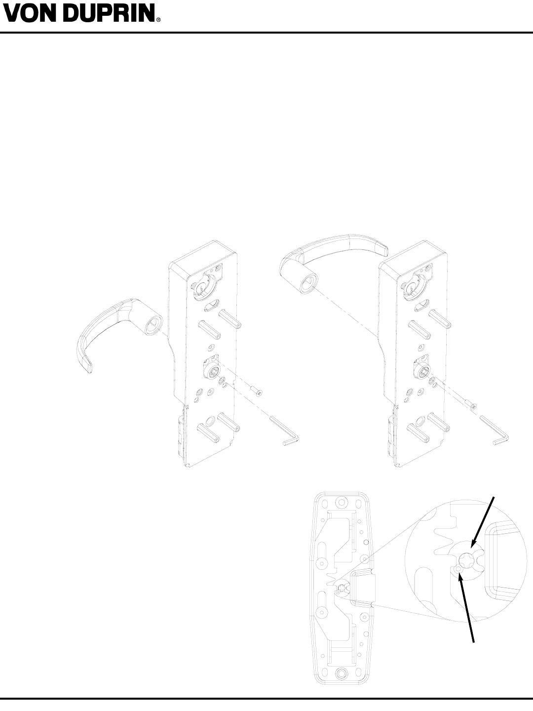
5. SET HAND OF TRIM (IF REQUIRED):
A. Install lever using hex head screw and 5/32” allen wrench as shown.
B. TEST: Use key override to engage lever to test for cam rotation. Output cam should be
observed to rotate when lever is depressed.
6. INSTALL STOP SCREW:
A. Push down on lever, observe output cam rotate, then install stop screw as shown below
(while keeping the lever depressed).
B. TEST: Lever should rotate down, when pushed; lever should not lift up.
LHR
RHR
SCREW
CAM
7. PREP EXIT DEVICE: Set exit device to
NL (“Night Latch”) function by inserting the
allen set screw (supplied in screw pack) as
shown in illustration to right. If the set screw
is present go to next step.
- PAGE 6 -
FORM 60993 Rev. A
VIP 993 OPEN ARCHITECTURE TRIM
Installation Instructions - HARDWIRED
01-05-2004
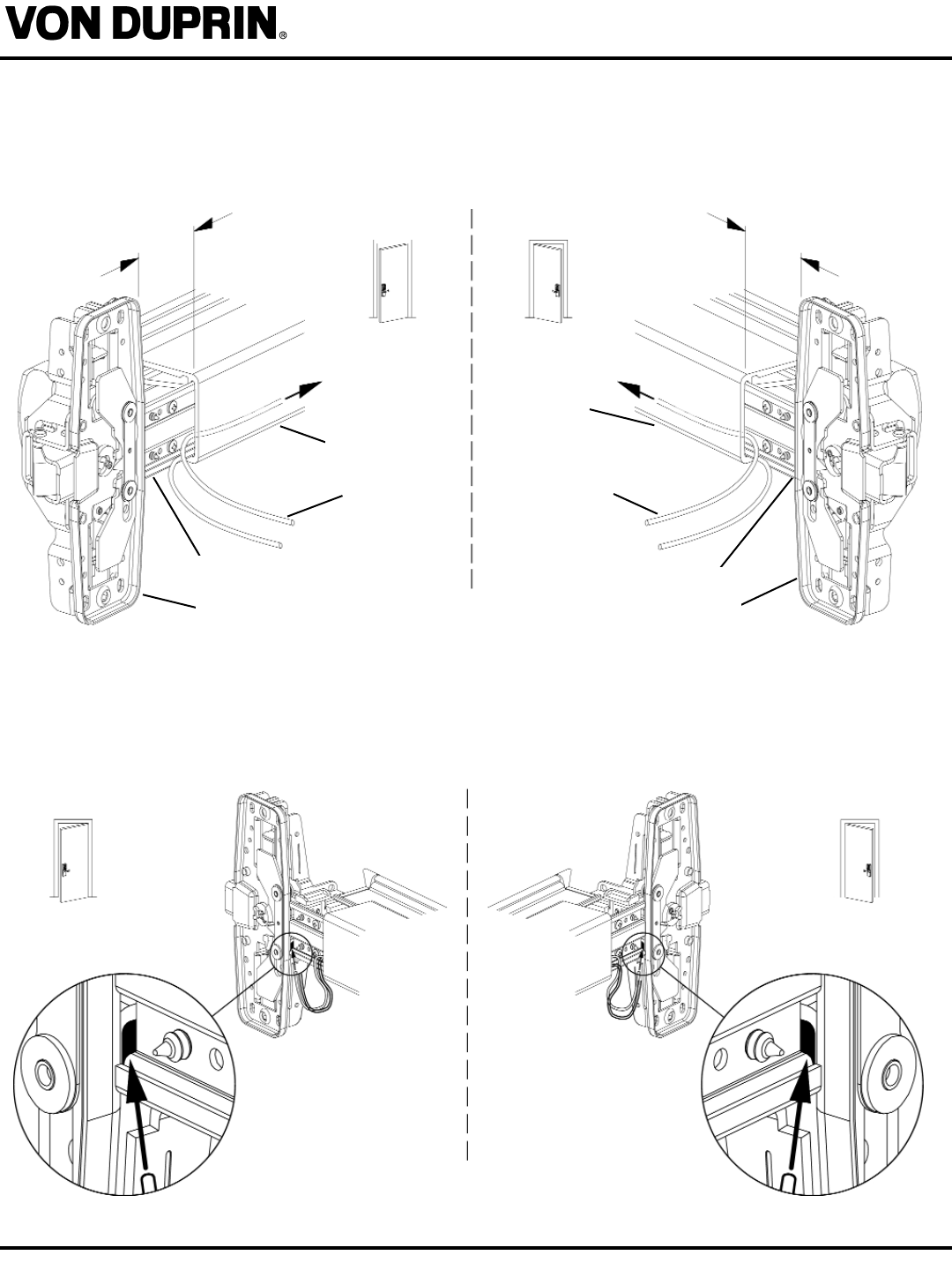
8. ROUTE VIP993 HW WIRES THROUGH EXIT DEVICE.
a. Slide mechanism case 2” away from center case
b. Push VIP993HW cables down length of the device between mechanism case and base plate.
Leave 12” of cable protruding from center case end of device.
c. Push VIP993 HW cable through opening in bottom of center case.
d. Slide mechanism case back against center case.
Important!
Be careful not to pinch cables when sliding
mechanism case back against center case.
RHR LHR
RHR LHR
2” 2”
MECHANISM
CASE
BASE PLATE
CENTER CASE
LEAVE 12” OF
WIRE
PROTRUDING
MECHANISM
CASE
BASE PLATE
CENTER CASE
LEAVE 12” OF
WIRE
PROTRUDING
- PAGE 7 -
VIP 993 OPEN ARCHITECTURE TRIM
Installation Instructions - HARDWIRED
Form 61997 Rev. A 01-05-2004
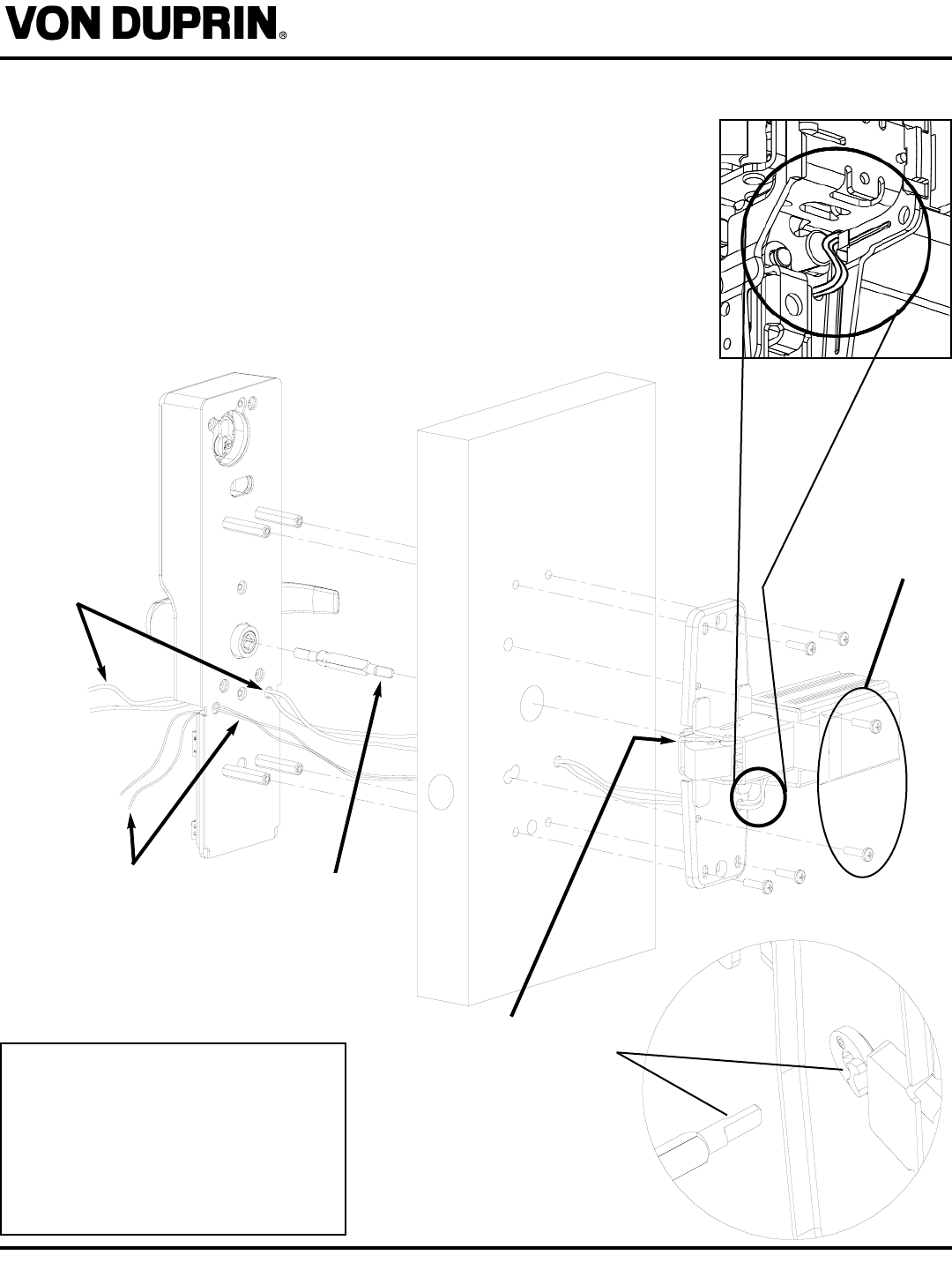
9. RE-INSTALL EXIT DEVICE: Carefully fish wiring from exit device through latch head wire hole
and through door. Fish wiring from door switch through hole in trim as shown.Install exit device onto
door. Place spindle into exit device. The end of spindle with the identifica-
tion notches inserts into the cam in the centercase for RHR. For LHR the
end of the spindle with the notches inserts into the trim as shown below.
(See DETAIL)
10. ENGAGE SPINDLE AND TEST: Fish wiring through VIP993 wire hole.
Align spindle with lever and place trim onto door. The unlocked lever
should retract the latch fully. If there is only a partial retraction of the latch
the spindle is in backwards. If the lever can not be pushed down the lever
stop screw is not in the correct hole. (See step 6 to correct this.)
11. SECURE TRIM: Install 4 screws to secure trim to door / latch head.
NOTCHED END
INSERTS INTO
TRIM FOR LHR.
(INSERTS INTO
BAR FOR RHR)
LHR SHOWN
RHR IS
OPPOSITE
NOTE: The tab on the spindle, which
engages the exit device latch head, is
sized for optimal performance in most
installations. Older exit devices may have
cams which are smaller and do not allow
the spindle to fit. In these cases, the tab
may be filed to fit the cam. Do not over-file
or full bolt retraction will be lost.
IF THESE TWO
SCREWS WERE
PRESENT IN
THE ORIGINAL
INSTALLATION,
RE-INSTALL
THEM.
IMPORTANT!
SIDE OF SPINDLE WITH LONGER
STEP GOES AGAINST RAISED “C”
SHAPE AREA OF CAM ON LATCH
HEAD.
DETAIL
WIRES FROM
EXIT DEVICE
WIRES FROM
DOOR SWITCH
- PAGE 8 -
VIP 993 OPEN ARCHITECTURE TRIM
Installation Instructions - HARDWIRED
Form 61997 Rev. A 01-05-2004
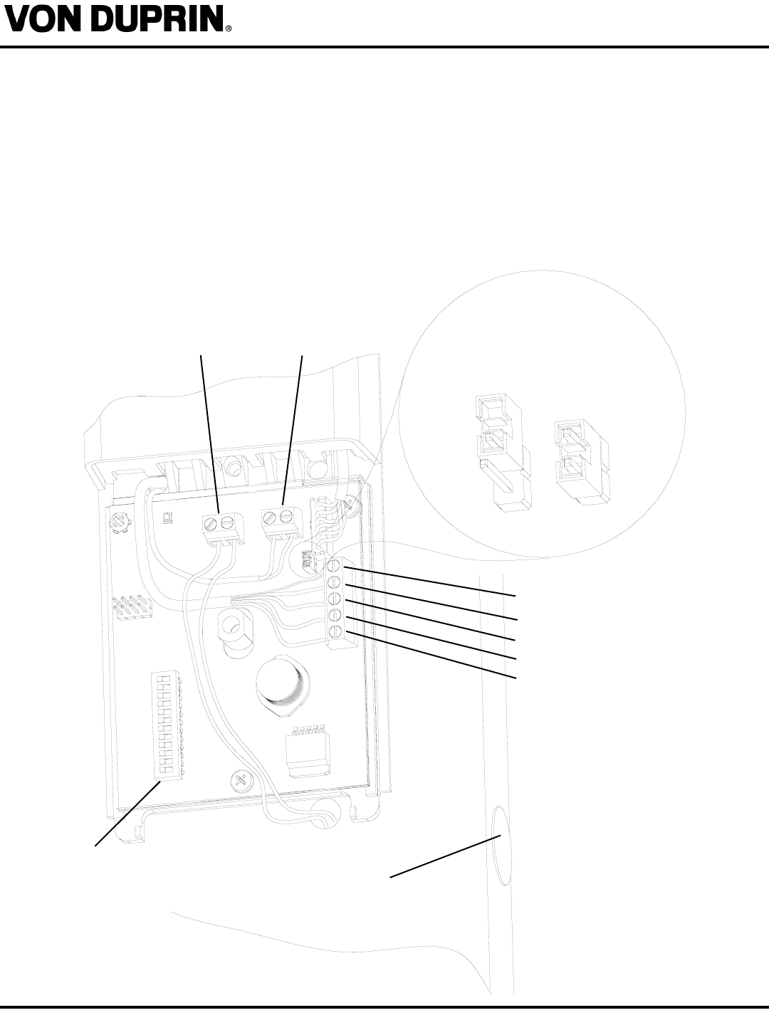
OFF (PARKED)
ON
TERMINATION
RESISTOR:
DOOR STATUS
SWITCH INPUT
(YELLOW WIRES)
DOOR STATUS
SWITCH
REX SWITCH INPUT
FROM EXIT DEVICE
(2-CONDUCTOR
WIRE RED/WHITE)
12. MAKE WIRING HARNESS CONNECTIONS :
A. Connect 4-conductor shielded wire (from exit device) to 5 position terminal block.
B. Connect 2-conductor wire (from REX switch in exit device) to terminal block.
C. Connect in DOOR STATUS SWITCH as shown.
D. Set lock address. See dipswitch settings on next page.
E. Verify correct lock type setting (FSE/FSA) - see dip switch setting. Note: as ordered from the factory.
F. If lock is the one farthest away from PIB set termination resistor to “on”. All others should be in the “off/parked” posi-
tion.
IMPORTANT! See PIB manual for additional connecting instructions.
SHIELD (N/A - METAL)
DATA A WHITE
DATA B GREEN
GROUND BLACK
V+ RED
SEE NEXT PAGE
FOR DIP SWITCH
SETTINGS
- PAGE 9 -
VIP 993 OPEN ARCHITECTURE TRIM
Installation Instructions - HARDWIRED
Form 61997 Rev. A 01-05-2004
13. REX switch connection:
On the inside of the exit device:
Connect the 2-conductor black and white wire to the S-1 switch installed on the exit device to the
yellow and blue wires (it doesn’t matter which is connected to which). Be sure to connect them
securely so they don’t disconnect during operation.
Note: if the REX switch (S-1) is not used, see the information supplied with the panel to set up the
door zone without a rex/legal egress input to avoid a fault condition.
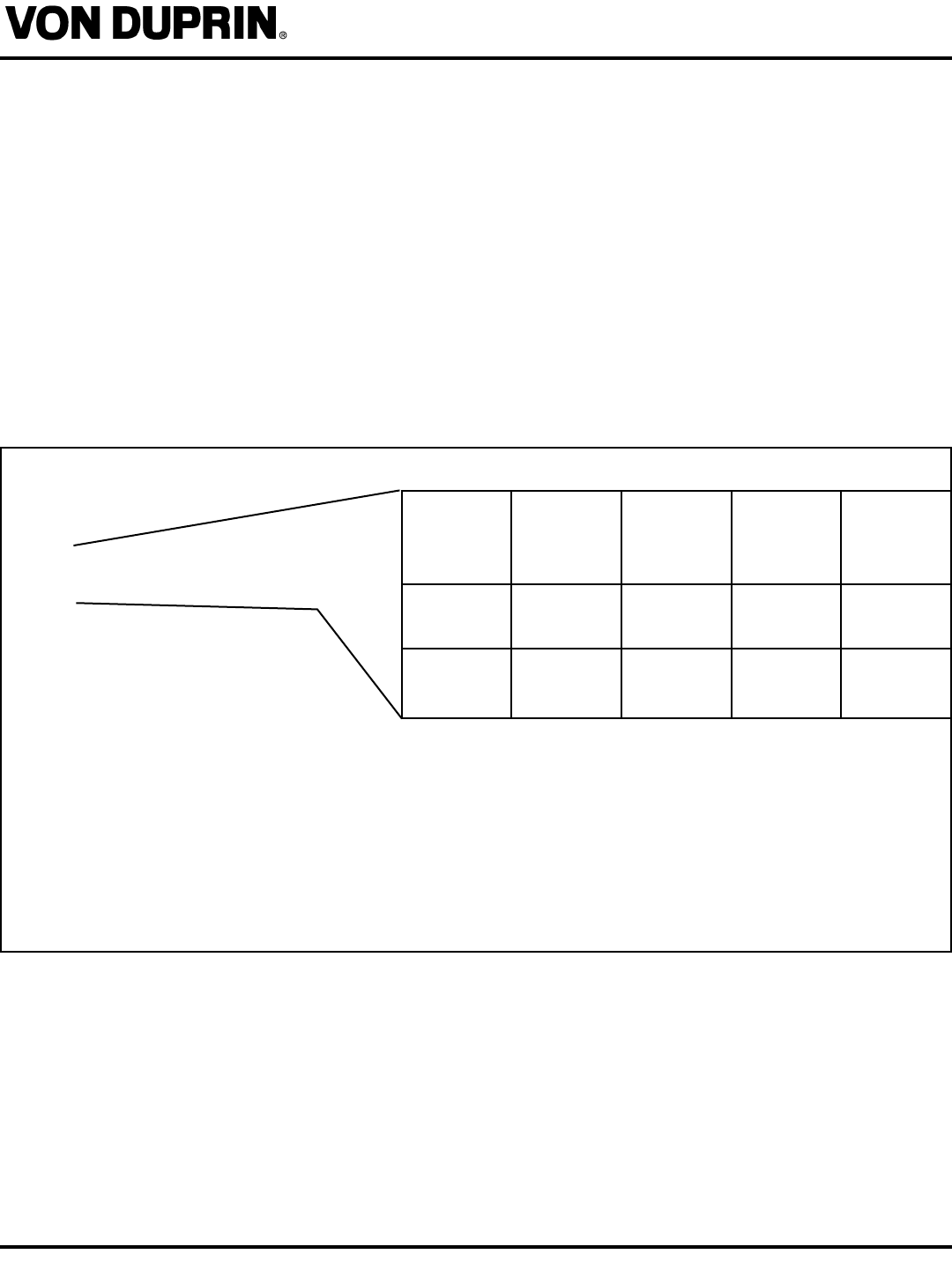
1: LOCK ADDRESS (SEE CHART)
2: LOCK ADDRESS (SEE CHART)
3: ALWAYS SET TO OFF
4: ALWAYS SET TO OFF
5: OFF = FAIL SECURE (FSE)
ON = FAIL SAFE (FSA)
6: OFF = ALL MG LOCKS
ON = ALL PX LOCKS
7: ALWAYS SET TO OFF
8: ALWAYS SET TO OFF
9: ALWAYS SET TO OFF
10: ALWAYS SET TO OFF
LOCK
ADDRESS
1
LOCK
ADDRESS
2
LOCK
ADDRESS
3
LOCK
ADDRESS
4
DIP SWITCH
1 OFF ON OFF ON
DIP SWITCH
2 OFF OFF ON ON
DIP
SWITCH
NUMBER:
Note:
Lock addresses must be used in sequence and cannot
be the same for any two locks connected to a PIB. For
example, if the system has three locks, use addresses
1, 2, and 3 (but not 4). Lock address will correspond to
panel address on the PIB.
DIP SWITCH SETTINGS:
- PAGE 10 -
FORM 60993 Rev. A
VIP 993 OPEN ARCHITECTURE TRIM
Installation Instructions - HARDWIRED
06/29/2001
14. INSTALL PC BOARD COVER:
See PIB manual and panel documentation for more wiring and set up information.