Schneider Electric IndustrieS NX2TO7 Control Units User Manual Micrologic X Control Unit User Guide 05 2016
Schneider Electric Industrie SAS Control Units Micrologic X Control Unit User Guide 05 2016
Contents
- 1. Users Manual (Statement)_rev.pdf
- 2. Users Manual-1.pdf
- 3. Users Manual-2.pdf
Users Manual-1.pdf
DOCA0102EN-00
www.schneider-electric.com
Micrologic X
DOCA010 2EN-00 05/201 6
Micrologic X
Control Unit
User Guide
05/2016

2DOCA0102EN-00 05/2016
The information provided in this documentation contains general descriptions and/or technical character-
istics of the performance of the products contained herein. This documentation is not intended as a
substitute for and is not to be used for determining suitability or reliability of these products for specific user
applications. It is the duty of any such user or integrator to perform the appropriate and complete risk
analysis, evaluation and testing of the products with respect to the relevant specific application or use
thereof. Neither Schneider Electric nor any of its affiliates or subsidiaries shall be responsible or liable for
misuse of the information contained herein. If you have any suggestions for improvements or amendments
or have found errors in this publication, please notify us.
No part of this document may be reproduced in any form or by any means, electronic or mechanical,
including photocopying, without express written permission of Schneider Electric.
All pertinent state, regional, and local safety regulations must be observed when installing and using this
product. For reasons of safety and to help ensure compliance with documented system data, only the
manufacturer should perform repairs to components.
When devices are used for applications with technical safety requirements, the relevant instructions must
be followed.
Failure to use Schneider Electric software or approved software with our hardware products may result in
injury, harm, or improper operating results.
Failure to observe this information can result in injury or equipment damage.
© 2016 Schneider Electric. All rights reserved.

DOCA0102EN-00 05/2016 3
Table of Contents
Safety Information. . . . . . . . . . . . . . . . . . . . . . . . . . . . . . . . . . . . . . . . . . . . 5
About the Book . . . . . . . . . . . . . . . . . . . . . . . . . . . . . . . . . . . . . . . . . . . . . . 7
Chapter 1 Introduction to the Micrologic X Control Unit . . . . . . . . . . . . . . . . . . . . . . . 9
Presentation . . . . . . . . . . . . . . . . . . . . . . . . . . . . . . . . . . . . . . . . . . . . . . . . . . . . . . . . . . . . . 10
The Range of Micrologic X Control Units . . . . . . . . . . . . . . . . . . . . . . . . . . . . . . . . . . . . . . . 11
Micrologic X Control Unit Description . . . . . . . . . . . . . . . . . . . . . . . . . . . . . . . . . . . . . . . . . . 12
Masterpact MTZ Mobile App . . . . . . . . . . . . . . . . . . . . . . . . . . . . . . . . . . . . . . . . . . . . . . . . . 15
Ecoreach Software . . . . . . . . . . . . . . . . . . . . . . . . . . . . . . . . . . . . . . . . . . . . . . . . . . . . . . . . 16
Optional Digital Modules for Micrologic X Control Units . . . . . . . . . . . . . . . . . . . . . . . . . . . . 17
Micrologic X Control Units in Digital Systems . . . . . . . . . . . . . . . . . . . . . . . . . . . . . . . . . . . . 18
Go2SE Landing Page . . . . . . . . . . . . . . . . . . . . . . . . . . . . . . . . . . . . . . . . . . . . . . . . . . . . . . 19
GoDigital . . . . . . . . . . . . . . . . . . . . . . . . . . . . . . . . . . . . . . . . . . . . . . . . . . . . . . . . . . . . . . . . 20
Installing and Removing Optional Digital Modules . . . . . . . . . . . . . . . . . . . . . . . . . . . . . . . . 21
Micrologic X Date and Time . . . . . . . . . . . . . . . . . . . . . . . . . . . . . . . . . . . . . . . . . . . . . . . . . 22
Micrologic X Power Supply . . . . . . . . . . . . . . . . . . . . . . . . . . . . . . . . . . . . . . . . . . . . . . . . . . 23
Chapter 2 Using Micrologic X Control Units . . . . . . . . . . . . . . . . . . . . . . . . . . . . . . . . 27
2.1 Presentation of HMIs . . . . . . . . . . . . . . . . . . . . . . . . . . . . . . . . . . . . . . . . . . . . . . . . . . . . . . . 28
Micrologic X HMIs . . . . . . . . . . . . . . . . . . . . . . . . . . . . . . . . . . . . . . . . . . . . . . . . . . . . . . . . . 29
Functions per HMI . . . . . . . . . . . . . . . . . . . . . . . . . . . . . . . . . . . . . . . . . . . . . . . . . . . . . . . . . 30
2.2 Using the Micrologic X HMI . . . . . . . . . . . . . . . . . . . . . . . . . . . . . . . . . . . . . . . . . . . . . . . . . . 31
Micrologic X HMI Description . . . . . . . . . . . . . . . . . . . . . . . . . . . . . . . . . . . . . . . . . . . . . . . . 32
HMI Display Modes . . . . . . . . . . . . . . . . . . . . . . . . . . . . . . . . . . . . . . . . . . . . . . . . . . . . . . . . 34
Quick View Mode. . . . . . . . . . . . . . . . . . . . . . . . . . . . . . . . . . . . . . . . . . . . . . . . . . . . . . . . . . 35
Tree Navigation Mode . . . . . . . . . . . . . . . . . . . . . . . . . . . . . . . . . . . . . . . . . . . . . . . . . . . . . . 38
Measures Menu. . . . . . . . . . . . . . . . . . . . . . . . . . . . . . . . . . . . . . . . . . . . . . . . . . . . . . . . . . . 45
Alarms & History Menu . . . . . . . . . . . . . . . . . . . . . . . . . . . . . . . . . . . . . . . . . . . . . . . . . . . . . 50
Maintenance Menu . . . . . . . . . . . . . . . . . . . . . . . . . . . . . . . . . . . . . . . . . . . . . . . . . . . . . . . . 51
Configuration Menu . . . . . . . . . . . . . . . . . . . . . . . . . . . . . . . . . . . . . . . . . . . . . . . . . . . . . . . . 52
Protection Menu . . . . . . . . . . . . . . . . . . . . . . . . . . . . . . . . . . . . . . . . . . . . . . . . . . . . . . . . . . 54
Pop-up Event Messages . . . . . . . . . . . . . . . . . . . . . . . . . . . . . . . . . . . . . . . . . . . . . . . . . . . . 57
Chapter 3 Protection Functions. . . . . . . . . . . . . . . . . . . . . . . . . . . . . . . . . . . . . . . . . . 59
3.1 Introduction . . . . . . . . . . . . . . . . . . . . . . . . . . . . . . . . . . . . . . . . . . . . . . . . . . . . . . . . . . . . . . 60
Electrical Distribution Protection . . . . . . . . . . . . . . . . . . . . . . . . . . . . . . . . . . . . . . . . . . . . . . 60
3.2 Standard Protection Functions . . . . . . . . . . . . . . . . . . . . . . . . . . . . . . . . . . . . . . . . . . . . . . . 64
Long-Time Overcurrent Protection (L or ANSI Code 49RMS). . . . . . . . . . . . . . . . . . . . . . . . 65
Short-Time Overcurrent Protection (S or ANSI Code 51) . . . . . . . . . . . . . . . . . . . . . . . . . . . 68
Instantaneous Overcurrent Protection (I or ANSI Code 50) . . . . . . . . . . . . . . . . . . . . . . . . . 70
Ground-Fault Protection (G or ANSI Code 50G/51G) . . . . . . . . . . . . . . . . . . . . . . . . . . . . . . 72
Earth-Leakage Protection (ANSI Code 50G/51G). . . . . . . . . . . . . . . . . . . . . . . . . . . . . . . . . 74
Neutral Protection . . . . . . . . . . . . . . . . . . . . . . . . . . . . . . . . . . . . . . . . . . . . . . . . . . . . . . . . . 76
Dual Settings . . . . . . . . . . . . . . . . . . . . . . . . . . . . . . . . . . . . . . . . . . . . . . . . . . . . . . . . . . . . . 78
Zone Selective Interlocking (ZSI) . . . . . . . . . . . . . . . . . . . . . . . . . . . . . . . . . . . . . . . . . . . . . 80
3.3 Setting Guidelines . . . . . . . . . . . . . . . . . . . . . . . . . . . . . . . . . . . . . . . . . . . . . . . . . . . . . . . . . 84
Protection Setting Guidelines . . . . . . . . . . . . . . . . . . . . . . . . . . . . . . . . . . . . . . . . . . . . . . . . 85
Setting the Long-Time Overcurrent Protection (L or ANSI Code 49RMS) . . . . . . . . . . . . . . 87
Setting the Short-Time Overcurrent Protection (S or ANSI Code 51) . . . . . . . . . . . . . . . . . . 90
Setting the Instantaneous Overcurrent Protection (I or ANSI Code 50) . . . . . . . . . . . . . . . . 92
Selectivity . . . . . . . . . . . . . . . . . . . . . . . . . . . . . . . . . . . . . . . . . . . . . . . . . . . . . . . . . . . . . . . 93

4DOCA0102EN-00 05/2016
Chapter 4 Metering Functions. . . . . . . . . . . . . . . . . . . . . . . . . . . . . . . . . . . . . . . . . . . . 95
4.1 Standard Metering Functions. . . . . . . . . . . . . . . . . . . . . . . . . . . . . . . . . . . . . . . . . . . . . . . . .96
Measurement Accuracy in Accordance with IEC 61557-12 . . . . . . . . . . . . . . . . . . . . . . . . . . 97
Measurement Characteristics . . . . . . . . . . . . . . . . . . . . . . . . . . . . . . . . . . . . . . . . . . . . . . . . 102
Measurement Availability . . . . . . . . . . . . . . . . . . . . . . . . . . . . . . . . . . . . . . . . . . . . . . . . . . . .107
Network Settings . . . . . . . . . . . . . . . . . . . . . . . . . . . . . . . . . . . . . . . . . . . . . . . . . . . . . . . . . . 113
Real-Time Measurements . . . . . . . . . . . . . . . . . . . . . . . . . . . . . . . . . . . . . . . . . . . . . . . . . . . 114
Power Metering . . . . . . . . . . . . . . . . . . . . . . . . . . . . . . . . . . . . . . . . . . . . . . . . . . . . . . . . . . . 117
Power Calculation Algorithm . . . . . . . . . . . . . . . . . . . . . . . . . . . . . . . . . . . . . . . . . . . . . . . . . 120
Energy Metering. . . . . . . . . . . . . . . . . . . . . . . . . . . . . . . . . . . . . . . . . . . . . . . . . . . . . . . . . . . 121
Harmonic Currents and Voltages. . . . . . . . . . . . . . . . . . . . . . . . . . . . . . . . . . . . . . . . . . . . . . 123
Power Quality Indicators . . . . . . . . . . . . . . . . . . . . . . . . . . . . . . . . . . . . . . . . . . . . . . . . . . . . 124
Power Factor PF and cos ϕ Measurement . . . . . . . . . . . . . . . . . . . . . . . . . . . . . . . . . . . . . . 126
4.2 Optional Metering Functions . . . . . . . . . . . . . . . . . . . . . . . . . . . . . . . . . . . . . . . . . . . . . . . . . 129
Energy per Phase . . . . . . . . . . . . . . . . . . . . . . . . . . . . . . . . . . . . . . . . . . . . . . . . . . . . . . . . . 129
Chapter 5 Diagnostic and Maintenance Functions . . . . . . . . . . . . . . . . . . . . . . . . . . . . 131
5.1 Maintenance Assistance . . . . . . . . . . . . . . . . . . . . . . . . . . . . . . . . . . . . . . . . . . . . . . . . . . . . 132
Maintenance Schedule. . . . . . . . . . . . . . . . . . . . . . . . . . . . . . . . . . . . . . . . . . . . . . . . . . . . . .133
Circuit Breaker Overview . . . . . . . . . . . . . . . . . . . . . . . . . . . . . . . . . . . . . . . . . . . . . . . . . . . .134
5.2 Standard Diagnostic Functions . . . . . . . . . . . . . . . . . . . . . . . . . . . . . . . . . . . . . . . . . . . . . . . 135
Health Monitoring. . . . . . . . . . . . . . . . . . . . . . . . . . . . . . . . . . . . . . . . . . . . . . . . . . . . . . . . . . 136
Circuit Breaker Monitoring . . . . . . . . . . . . . . . . . . . . . . . . . . . . . . . . . . . . . . . . . . . . . . . . . . . 137
Monitoring the Tripping Function . . . . . . . . . . . . . . . . . . . . . . . . . . . . . . . . . . . . . . . . . . . . . . 138
Monitoring the Opening/Closing Function . . . . . . . . . . . . . . . . . . . . . . . . . . . . . . . . . . . . . . . 139
Monitoring the Contact State . . . . . . . . . . . . . . . . . . . . . . . . . . . . . . . . . . . . . . . . . . . . . . . . . 140
Monitoring the Internal Functioning of the Micrologic X control unit. . . . . . . . . . . . . . . . . . . . 141
Monitoring the ULP Modules . . . . . . . . . . . . . . . . . . . . . . . . . . . . . . . . . . . . . . . . . . . . . . . . . 142
Monitoring the Circuit Breaker Service Life . . . . . . . . . . . . . . . . . . . . . . . . . . . . . . . . . . . . . . 143
5.3 Optional Diagnostic Functions . . . . . . . . . . . . . . . . . . . . . . . . . . . . . . . . . . . . . . . . . . . . . . . .144
Power Restoration Assistant Digital Module . . . . . . . . . . . . . . . . . . . . . . . . . . . . . . . . . . . . . 145
Masterpact Operation Assistant Digital Module . . . . . . . . . . . . . . . . . . . . . . . . . . . . . . . . . . . 146
Waveform Capture on Trip Event Digital Module. . . . . . . . . . . . . . . . . . . . . . . . . . . . . . . . . . 147
Chapter 6 Operation Functions . . . . . . . . . . . . . . . . . . . . . . . . . . . . . . . . . . . . . . . . . . . 149
Control Modes . . . . . . . . . . . . . . . . . . . . . . . . . . . . . . . . . . . . . . . . . . . . . . . . . . . . . . . . . . . . 150
Closing Function . . . . . . . . . . . . . . . . . . . . . . . . . . . . . . . . . . . . . . . . . . . . . . . . . . . . . . . . . . 151
Opening Function. . . . . . . . . . . . . . . . . . . . . . . . . . . . . . . . . . . . . . . . . . . . . . . . . . . . . . . . . . 152
Chapter 7 Communication Functions . . . . . . . . . . . . . . . . . . . . . . . . . . . . . . . . . . . . . . 153
Bluetooth Low Energy Communication . . . . . . . . . . . . . . . . . . . . . . . . . . . . . . . . . . . . . . . . . 154
NFC Communication . . . . . . . . . . . . . . . . . . . . . . . . . . . . . . . . . . . . . . . . . . . . . . . . . . . . . . .156
IEEE 802.15.4 Communication . . . . . . . . . . . . . . . . . . . . . . . . . . . . . . . . . . . . . . . . . . . . . . . 157
USB Connection. . . . . . . . . . . . . . . . . . . . . . . . . . . . . . . . . . . . . . . . . . . . . . . . . . . . . . . . . . . 159
Cybersecurity Recommendations . . . . . . . . . . . . . . . . . . . . . . . . . . . . . . . . . . . . . . . . . . . . . 160
Chapter 8 Event Management . . . . . . . . . . . . . . . . . . . . . . . . . . . . . . . . . . . . . . . . . . . 163
Event Management . . . . . . . . . . . . . . . . . . . . . . . . . . . . . . . . . . . . . . . . . . . . . . . . . . . . . . . . 164
Event Status Overview. . . . . . . . . . . . . . . . . . . . . . . . . . . . . . . . . . . . . . . . . . . . . . . . . . . . . . 165
Event Notifications . . . . . . . . . . . . . . . . . . . . . . . . . . . . . . . . . . . . . . . . . . . . . . . . . . . . . . . . . 169
Event Status Table. . . . . . . . . . . . . . . . . . . . . . . . . . . . . . . . . . . . . . . . . . . . . . . . . . . . . . . . . 170
Event History . . . . . . . . . . . . . . . . . . . . . . . . . . . . . . . . . . . . . . . . . . . . . . . . . . . . . . . . . . . . . 171
Event List . . . . . . . . . . . . . . . . . . . . . . . . . . . . . . . . . . . . . . . . . . . . . . . . . . . . . . . . . . . . . . . . 173
Appendices . . . . . . . . . . . . . . . . . . . . . . . . . . . . . . . . . . . . . . . . . . . . . . . . . . . . . . 177
Appendix A Title of Chapter. . . . . . . . . . . . . . . . . . . . . . . . . . . . . . . . . . . . . . . . . . . . . . . 179
DOCA0102EN-00 05/2016 5
Safety Information
Important Information
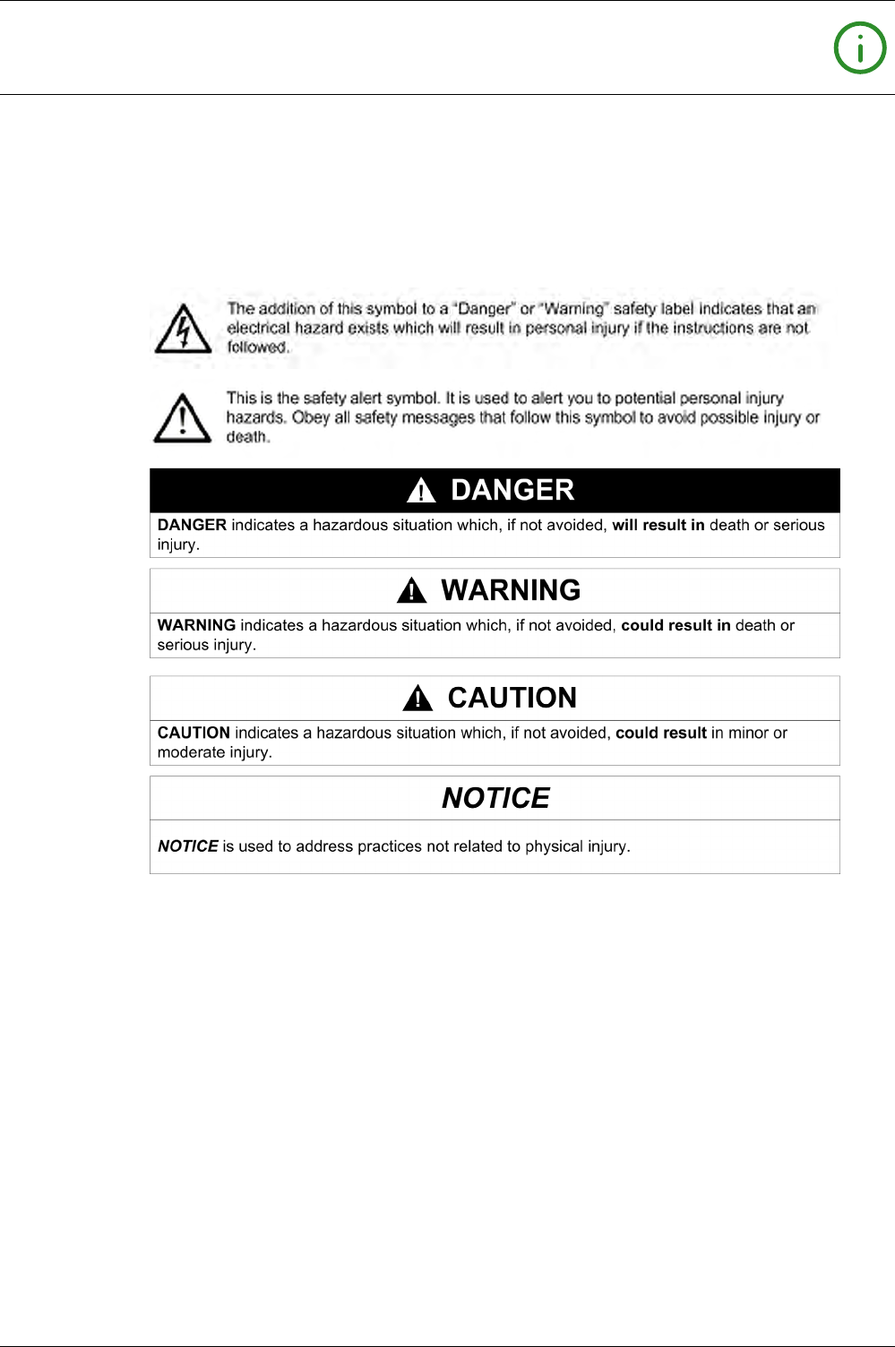
NOTICE
Read these instructions carefully, and look at the equipment to become familiar with the device before
trying to install, operate, service, or maintain it. The following special messages may appear throughout
this documentation or on the equipment to warn of potential hazards or to call attention to information that
clarifies or simplifies a procedure.
PLEASE NOTE
Electrical equipment should be installed, operated, serviced, and maintained only by qualified personnel.
No responsibility is assumed by Schneider Electric for any consequences arising out of the use of this
material.
A qualified person is one who has skills and knowledge related to the construction and operation of
electrical equipment and its installation, and has received safety training to recognize and avoid the
hazards involved.

6DOCA0102EN-00 05/2016

DOCA0102EN-00 05/2016 7
About the Book
At a Glance
Document Scope
The aim of this guide is to provide users, installers, and maintenance personnel with the technical
information needed to operate Micrologic™ X control units in Masterpact™ MTZ circuit breakers.
Validity Note
This guide applies to the following control units:
Micrologic 2.0 X
Micrologic 5.0 X
Micrologic 6.0 X
Micrologic 7.0 X
Related Documents
You can download these technical publications and other technical information from our website at
http://download.schneider-electric.com
Trademark Notice
All trademarks are owned by Schneider Electric Industries SAS or its affiliated companies.
Licensing Information for Cryptographic Software
Copyright © 1995-1997 Eric Young (eay@cryptsoft.com).
Copyright © 1998-2006 The OpenSSL Project. All rights reserved.
Copyright © 2002 Sun Microsystems, Inc. All rights reserved.
This product includes cryptographic software written by Eric Young (eay@cryptsoft.com).
Title of Documentation Reference Number
Masterpact MTZ1 Circuit Breakers and Switch-Disconnectors - User
Guide
DOCA0100EN
DOCA0100ES
DOCA0100FR
DOCA0100ZH
Masterpact MTZ2/MTZ3 Circuit Breakers and Switch-Disconnectors
- User Guide
DOCA0101EN
DOCA0101ES
DOCA0101FR
DOCA0101ZH
Masterpact MTZ - Modbus Communication Guide DOCA0105EN
DOCA0105ES
DOCA0105FR
DOCA0105ZH
Masterpact MTZ Cyber Security Guide DOCA0122EN
IO Input/Output Application Module for One Circuit Breaker User
Guide
DOCA0055EN
DOCA0055FR
DOCA0055ES
DOCA0055ZH
IFE Ethernet Interface User Guide DOCA0084EN
DOCA0084FR
DOCA0084ES
DOCA0084ZH
EIFE Embedded Ethernet Interface User Guide DOCA0106EN

8DOCA0102EN-00 05/2016
THIS SOFTWARE IS PROVIDED BY ERIC YOUNG “AS IS” AND ANY EXPRESS OR IMPLIED
WARRANTIES, INCLUDING, BUT NOT LIMITED TO, THE IMPLIED WARRANTIES OF MERCHANT-
ABILITY AND FITNESS FOR A PARTICULAR PURPOSE ARE DISCLAIMED. IN NO EVENT SHALL THE
AUTHOR OR CONTRIBUTORS BE LIABLE FOR ANY DIRECT, INDIRECT, INCIDENTAL, SPECIAL,
EXEMPLARY, OR CONSEQUENTIAL DAMAGES (INCLUDING, BUT NOT LIMITED TO,
PROCUREMENT OF SUBSTITUTE GOODS OR SERVICES; LOSS OF USE, DATA, OR PROFITS; OR
BUSINESS INTERRUPTION) HOWEVER CAUSED AND ON ANY THEORY OF LIABILITY, WHETHER
IN CONTRACT, STRICT LIABILITY, OR TORT (INCLUDING NEGLIGENCE OR OTHERWISE) ARISING
IN ANY WAY OUT OF THE USE OF THIS SOFTWARE, EVEN IF ADVISED OF THE POSSIBILITY OF
SUCH DAMAGE.
This product includes software developed by the OpenSSL Project for use in the OpenSSL Toolkit
(http://www.openssl.org/).
THIS SOFTWARE IS PROVIDED BY THE OpenSSL PROJECT “AS IS” AND ANY EXPRESSED OR
IMPLIED WARRANTIES, INCLUDING, BUT NOT LIMITED TO, THE IMPLIED WARRANTIES OF
MERCHANTABILITY AND FITNESS FOR A PARTICULAR PURPOSE ARE DISCLAIMED. IN NO EVENT
SHALL THE OpenSSL PROJECT OR ITS CONTRIBUTORS BE LIABLE FOR ANY DIRECT, INDIRECT,
INCIDENTAL, SPECIAL, EXEMPLARY, OR CONSEQUENTIAL DAMAGES (INCLUDING, BUT NOT
LIMITED TO, PROCUREMENT OF SUBSTITUTE GOODS OR SERVICES; LOSS OF USE, DATA, OR
PROFITS; OR BUSINESS INTERRUPTION) HOWEVER CAUSED AND ON ANY THEORY OF
LIABILITY, WHETHER IN CONTRACT, STRICT LIABILITY, OR TORT (INCLUDING NEGLIGENCE OR
OTHERWISE) ARISING IN ANY WAY OUT OF THE USE OF THIS SOFTWARE, EVEN IF ADVISED OF
THE POSSIBILITY OF SUCH DAMAGE.
Licensing Information for USB Communication
Copyright © 2010 Texas Instruments Incorporated (http://www.ti.com/).
This product includes software developed by Texas Instruments Incorporated (http://www.ti.com/).
THIS SOFTWARE IS PROVIDED BY THE COPYRIGHT HOLDERS AND CONTRIBUTORS "AS IS" AND
ANY EXPRESS OR IMPLIED WARRANTIES, INCLUDING, BUT NOT LIMITED TO, THE IMPLIED
WARRANTIES OF MERCHANTABILITY AND FITNESS FOR A PARTICULAR PURPOSE ARE
DISCLAIMED. IN NO EVENT SHALL THE COPYRIGHT OWNER OR CONTRIBUTORS BE LIABLE FOR
ANY DIRECT, INDIRECT, INCIDENTAL, SPECIAL, EXEMPLARY, OR CONSEQUENTIAL DAMAGES
(INCLUDING, BUT NOT LIMITED TO, PROCUREMENT OF SUBSTITUTE GOODS OR SERVICES;
LOSS OF USE, DATA, OR PROFITS; OR BUSINESS INTERRUPTION) HOWEVER CAUSED AND ON
ANY THEORY OF LIABILITY, WHETHER IN CONTRACT, STRICT LIABILITY, OR TORT (INCLUDING
NEGLIGENCE OR OTHERWISE) ARISING IN ANY WAY OUT OF THE USE OF THIS SOFTWARE,
EVEN IF ADVISED OF THE POSSIBILITY OF SUCH DAMAGE.

DOCA0102EN-00 05/2016 9
Micrologic X
Introducti on to the Micr ologic X C ontrol Unit
DOCA0 102EN-00 05/2016
Introduction to the Microlog ic X Control Un it
Chapter 1
Introduction to the Micrologic X Control Unit
What Is in This Chapter?
This chapter contains the following topics:
Topic Page
Presentation 10
The Range of Micrologic X Control Units 11
Micrologic X Control Unit Description 12
Masterpact MTZ Mobile App 15
Ecoreach Software 16
Optional Digital Modules for Micrologic X Control Units 17
Micrologic X Control Units in Digital Systems 18
Go2SE Landing Page 19
GoDigital 20
Installing and Removing Optional Digital Modules 21
Micrologic X Date and Time 22
Micrologic X Power Supply 23

Introduction to the Micrologic X Control Unit
10 DOCA0102EN-00 05/2016
Presentation
Micrologic X Control Unit Overview
Masterpact MTZ circuit breakers with Micrologic X control units provide functions of protection, metering,
diagnostics, communication and remote operation. The control unit can be customized with optional Digital
Modules.
Micrologic X control units allow operation and monitoring of Masterpact MTZ circuit breakers locally or
remotely.
Protection
In addition to the standard range of protection (long-time overcurrent (L), short-time overcurrent (S),
instantaneous overcurrent (I), ground-fault (G), and earth-leakage (V)), additional features include:
Dual settings
Fine settings
Zone selective interlocking
Fast tripping
Metering
Micrologic X control units measure the following parameters:
Current
Voltage
Frequency
Power
Energy
Power factor
Minimum, maximum, and average values of a wide range of parameters are available.
Diagnostics and Maintenance
Diagnostic features help to:
Start the circuit breaker again after a trip as quickly as possible.
Limit the risk of power interruptions by monitoring the health of the Micrologic X control unit. Pop-up
messages alert the user in the case of necessary preventive maintenance.
Communication
Micrologic X control units support the following means of communication:
Wireless
Bluetooth
NFC
Ethernet
Through IFE webpages
Through embedded EIFE, with associated webpages (drawout devices only)
Local through connection to mini USB port
Wireless communication allows you to access status and measurements readings directly on a
smartphone using the Masterpact MTZ mobile App available to download and install.
Optional Digital Modules
The following Digital Modules can be downloaded from the Schneider Electric website to extend the
features available:
Energy per phase
Power restoration assistant
Masterpact operation assistant
Waveform capture on trip event
Introduction to the Micrologic X Control Unit
DOCA0102EN-00 05/2016 11
The Range of Micrologic X Control Units
Micrologic X Control Units
The range of Micrologic X control units offers different standard functions, described below.
Optional Digital Modules can be added to extend the functions available
(see page 17)
.
Presentation of Standard Functions
The following table indicates the standard features available on Masterpact MTZ with Micrologic X control
units:
Micrologic 2.0 X Micrologic 5.0 X Micrologic 6.0 X Micrologic 7.0 X
Long-time overcurrent protection (L) XXXX
Short-time overcurrent protection (S) – X X X
Instantaneous overcurrent protection (I) XXXX
Ground-fault protection (G) – – X –
Earth-leakage protection (V) –––X
Neutral protection XXXX
Dual settings XXXX
Overcurrent and trip cause indicators XXXX
Zone selective interlocking – X X X
Trip history XXXX
Setting change traceability XXXX
Embedded power meter XXXX
Embedded diagnostics XXXX
Introduction to the Micrologic X Control Unit
12 DOCA0102EN-00 05/2016
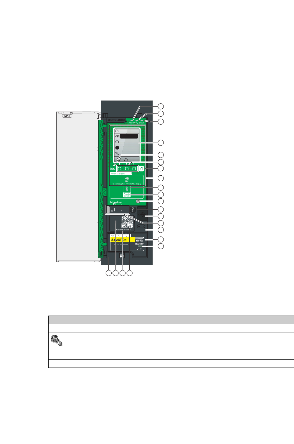
Micrologic X Control Unit Description
Introduction
The Micrologic X control unit includes:
Micrologic X health status LEDs
A local HMI comprising a graphic display with colored backlight, contextual buttons, and dedicated
buttons
LEDs to monitor circuit breaker operations, including the source of trips and alarms
Control Unit Description
Micrologic X Health Status LEDs
Local HMI Display Screen with Contextual Buttons and Dedicated Buttons
The local HMI screen and buttons
(see page 32)
are used to:
Navigate the menu structure.
Display monitored values.
Access and edit configuration settings.
A Ready LED
B Service LED
C ERMS LED (Reserved for future use)
D Graphic display screen
E Escape button ESC
F Three contextual buttons
G Home button
H NFC wireless communication zone
I Bluetooth LED
J Bluetooth activation button
K Test button for ground-fault and earth-leakage
protection (Micrologic 6.0 X and 7.0 X)
L Test/Reset button for trip cause LEDs and alarms
M Mini USB port under rubber cover
N Overload and trip cause LEDs
O Cover for battery
P VPS voltage power supply module (optional)
Q VPS LED to indicate that the VPS is supplying the
control unit
R QR code to product information
S Control unit identification number
T Control unit type
U Sensor plug with the rated current of the circuit
breaker
Test Reset
In 1600 A
DISCONNECT BEFORE
DIELECTRIC TEST
6.0 X
ID:
1989421527520002LV847604
In 1600 A
TRIP CAUSE
Op.
Isd
Ii
Ig
I n
Ir
OK
Home
OK
!
Quickview
Measures
Alarms & H...
Maintenan...
A
H
I
K
L
C
M
O
P
Q
N
U T S R
J
B
D
F
E
G
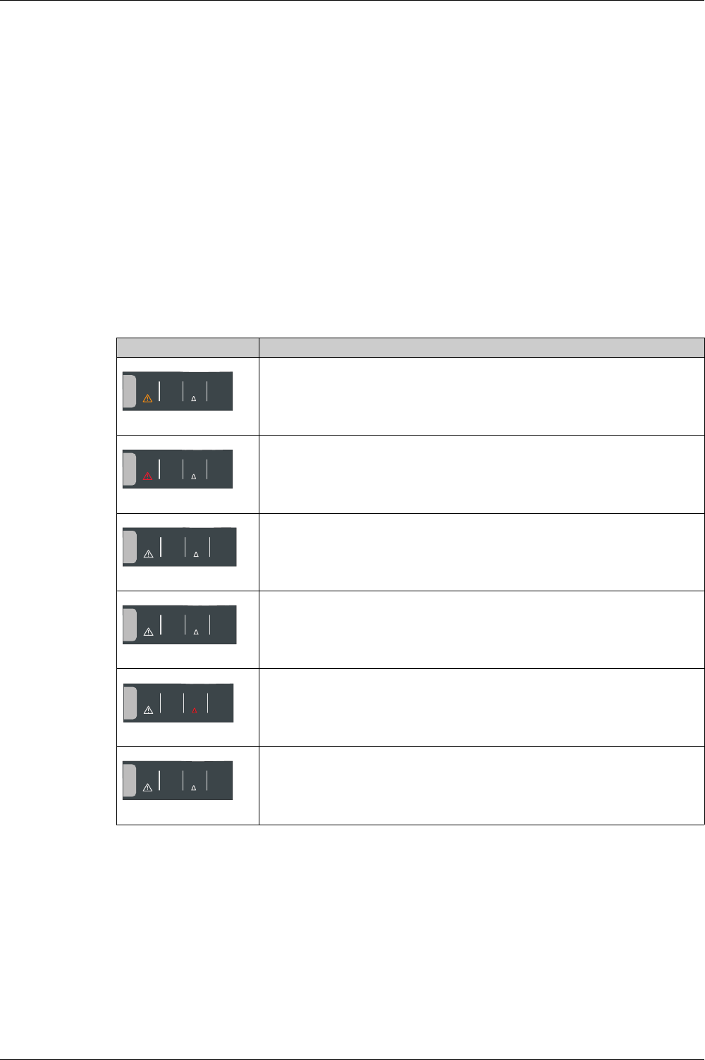
LED Description
Ready The Ready LED flashes when the control unit is ready to provide protection.
The service LED alerts the user to the overall health of the circuit breaker. There are three states:
Unlit LED: the circuit breaker is in good working order.
Orange LED: Non-urgent alert message.
Red LED: Alert message that requires immediate intervention.
ERMS The ERMS (Energy Reduction Maintenance Setting) LED is reserved for future use.
Introduction to the Micrologic X Control Unit
DOCA0102EN-00 05/2016 13
NFC Communication Zone
The NFC communication zone is used to establish an NFC connection
(seepage156)
between a
smartphone that has the Masterpact MTZ mobile App and the Micrologic X control unit. When the
connection is established, the circuit breaker operating data is automatically uploaded to the smartphone.
Bluetooth Activation Button and LED
The Bluetooth activation button is used to establish a Bluetooth Low Energy connection
(see page 154)
between a smartphone that has the Masterpact MTZ mobile App and the Micrologic X control unit. When
the connection is established, the circuit breaker can be monitored and controlled from the smartphone.
When the Bluetooth LED is flashing, it indicates that a Bluetooth connection is in progress.
Test Button
The test button is used to test the ground-fault protection for Micrologic 6.0 X
(see page 73)
and the earth-
leakage protection for Micrologic 7.0 X
(see page 74)
.
Overload and Trip Cause LEDs
The assignment of the four trip cause LEDs depends on the type of Micrologic X control unit.
NOTE: If the Micrologic X control unit is not powered the trip cause LEDs go off after 4 hours. Press the
Test/Reset button to light them again.
Test/Reset Button
The Test/Reset button performs the following functions:
Battery test. Press theTest/Reset button. The four trip cause LEDs light up for 1 second. If the LEDs do
not light, replace the battery.
Reset trip cause LED. When a trip cause LED is lit, press and hold the Test/Reset button for 3 seconds
to reset and switch off the trip cause LED and the service LED.
Reset the control unit (except standard protection functions). Press and hold the Test/Reset button for
15 seconds.
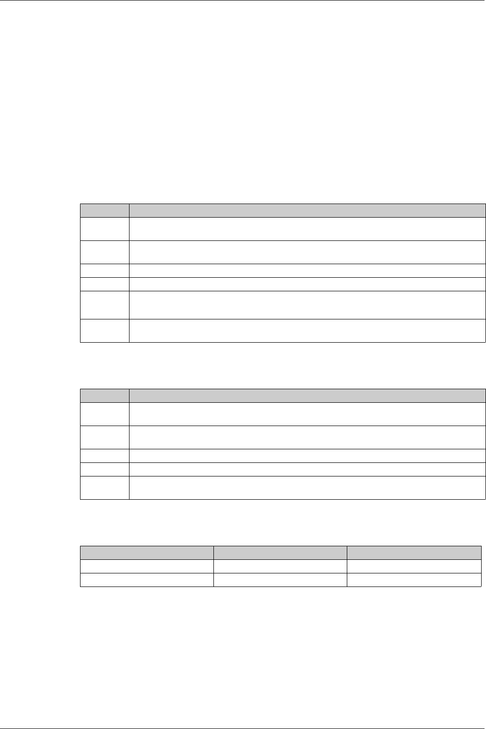
LEDs Description
Micrologic 2.0 X, 5.0 X, 6.0 X, 7.0 X: Overload pre-alarm, the load exceeds 90% of
the Ir setting of the long-time protection
Micrologic 2.0 X, 5.0 X, 6.0 X, 7.0 X: Overload alarm, the load exceeds 105% of the
Ir setting of the long-time protection
Micrologic 2.0 X, 5.0 X, 6.0 X, 7.0 X: trip due to the long-time protection.
Micrologic 2.0 X: trip due to the short-time protection.
Micrologic 5.0 X, 6.0 X, 7.0 X: trip due to the short-time protection or instantaneous
protection.
Micrologic 2.0 X, 5.0 X: Not used.
Micrologic 6.0 X: trip due to the ground-fault protection.
Micrologic 7.0 X: trip due to the earth-leakage protection.
Micrologic 2.0 X, 5.0 X, 6.0 X, 7.0 X: Trip due to other protection (optional
protections).
TRIP CAUSE
Op.
Isd
Ii
Ig
I n
Ir
TRIP CAUSE
Op.
Isd
Ii
Ig
I n
Ir
TRIP CAUSE
Op.
Isd
Ii
Ig
I n
Ir
TRIP CAUSE
Op.
Isd
Ii
Ig
I n
Ir
TRIP CAUSE
Op.
Isd
Ii
Ig
I n
Ir
TRIP CAUSE
Op.
Isd
Ii
Ig
I n
Ir

Introduction to the Micrologic X Control Unit
14 DOCA0102EN-00 05/2016
NOTE: After a battery test, any active trip cause LED is displayed again.
Mini USB Port
Remove the rubber cover of the mini USB port to connect the following devices:
A Mobile Power Pack to supply power to the Micrologic X control unit
(see page 23)
A PC equipped with Ecoreach software
(see page 159)
.
NOTE: It is not possible to connect a USB key to the Micrologic X control unit.
QR Code
When the QR code on the front face of a Micrologic X control unit is flashed by using a smartphone running
a QR code reader, a landing page is displayed.
The landing page displays some basic information about the device in a header, and a list of menus:
Characteristics
Download documents related to Masterpact and Micrologic X devices
Customer Care Center
Safe Repository
Masterpact MTZ mobile App
GoDigital
Control Unit Identification Number
The identification number is made up as follows:
The serial number of the Micrologic X control unit in the format FFFFFFYYWWDXXXXX
The sales reference of the control unit in the format LV8xxxxx
Use the identification number to register your Micrologic X control unit.
Registering your Micrologic X control unit ensures that your records are up to date and enables traceability.
Control Unit Type
This code denotes the type of Micrologic control unit:
The number (for example, 2.0) defines the types of protection provided by the control unit.
The letter (X) denotes the range.
Battery
The battery powers the trip cause LEDs in the absence of other power supply
(see page 25)
.
VPS
The VPS power supply module provides an internal voltage supply to the Micrologic X control unit
(see page 23)
.
The VPS module is optional for Micrologic 2.0 X, 5.0 X and 6.0 X.
The VPS module is supplied as standard for Micrologic 7.0 X.
Sensor Plug
The protection ranges depend on the rated current In, defined by the sensor plug inserted into the
Micrologic X control unit
(see page 60)
.

Introduction to the Micrologic X Control Unit
DOCA0102EN-00 05/2016 15
Masterpact MTZ Mobile App
Presentation
The Masterpact MTZ mobile App enables a smartphone to be used for rapid setting changes and a follow-
up of Masterpact MTZ circuit breakers with Micrologic X control units. It also enables information to be
shared, (for example, by email).
Downloading the Application
The Masterpact MTZ mobile App can be downloaded in the following ways:
Flashing the QR code on the front face of the Micrologic X control unit gives access to a landing page
where the mobile application is proposed
(see page 19)
From Google Play Store for Android smartphones
From App Store for iOS smartphones
The Masterpact MTZ mobile App is optimized for a 12.7 cm (5 inch) display screen.
Communicating with a Micrologic X Control Unit
Two means of communication are available to connect the Masterpact MTZ mobile App to a Micrologic X
control unit:
Bluetooth:
Display data
Configure general and protection settings
NFC (also available when control unit is not powered) (only available for Android smartphones):
Display selection of data
Establishing a Connection with a Micrologic X Control Unit
For the connection procedure refer to the specific topic:
Bluetooth connection procedure
(see page 154)
NFC connection procedure
(see page 156)
Using a Bluetooth Connection
Connecting to Masterpact MTZ mobile App with a Bluetooth connection gives access to and allows sharing
of the following information types:
Quick View: gives an overview of current levels per phase, the health of the circuit breaker, and recent
event history
Metering: displays values of current, rms voltages, network and energy in real-time
Protection Setting: displays settings currently selected and allows modification of settings
Status and Control: displays status of the circuit breaker and allows opening and closing operations to
be carried out.
Using an NFC Connection
Connecting to Masterpact MTZ mobile App with an NFC connection is possible when the Micrologic X
control unit is not powered. It gives access to the following information:
Information about the Micrologic X control unit
Last trip context: trip type; date and time of last trip; current values before trip
Protection settings (display only)
Access to Digital Modules
(see page 17)
for assistance after a trip

Introduction to the Micrologic X Control Unit
16 DOCA0102EN-00 05/2016
Ecoreach Software
Presentation
Ecoreach is an electrical asset management software package intended to assist with the designing,
testing, commissioning and maintenance phases of a project. It provides a simple way to configure, test
and commission electrical smart devices.
Ecoreach automatically discovers smart devices and allows them to be added for easy configuration.
Comprehensive reports can be generated as part of Factory Acceptance Test and Site Acceptance Test
reports to replace heavy manual work. Additionally, when the panels are under operation, any change of
settings made can be easily identified to provide system consistency during the operation and
maintenance phases.
Ecoreach software enables the configuration of Masterpact devices:
Micrologic X control unit
Communication interface modules: IFE interface and EIFE interface
ULP IO modules
M2C output module
For more information, refer to the
Ecoreach Online Help
.
The Ecoreach software is available at
www.schneider-electric.com
.
Key Features
Ecoreach performs the following actions for the supported devices and modules:
Create projects by device discovery
Perform communication wiring test on entire project, generate and print test reports
Configuration or settings download and upload for multiple devices
Install digital modules
Compare settings between project (original settings) and device (current settings)
Generate comprehensive project reports
Check system-level firmware status and upgrade devices
Provide safe repository of projects in Ecoreach Cloud
Read information (alarms, measurements, parameters) and display diagnosis information
Export logbook of events and waveform capture

Introduction to the Micrologic X Control Unit
DOCA0102EN-00 05/2016 17
Optional Digital Modules for Micrologic X Control Units
Presentation
Digital Modules are optional modules that extend the features available across the range of Micrologic X
control units.
They are available to purchase:
When the Micrologic X control unit is initially ordered
At any time after installation of the circuit breaker and Micrologic X control unit, by accessing the
GoDigital marketplace
Digital Modules can be purchased, downloaded and installed on a Micrologic X control unit without
interrupting the services of the functions provided by the control unit.
Take the following steps to purchase and install optional Digital Modules:
Access GoDigital
(see page 20)
Choose Digital Modules for your control unit and purchase them
Open the email and click the link to download the Digital Module delivery package to your PC
Connect Ecoreach software to your Micrologic X control unit to install your Digital Module
(see page 21)
Digital Modules
The following table presents the Digital Modules available for installation:
Digital Module Description Function
Energy per phase
(see page 129)
Analysis of energy consumption per phase. Metering
Power restoration assistant
(see page 145)
Assistance in restoring power quickly after a trip. Diagnostics
Masterpact operation
assistant
(see page 146)
Assistance in closing the circuit breaker after a trip. Diagnostics
Waveform capture on trip
event
(see page 147)
Displays interrupted phase and neutral currents
after a trip.
Diagnostics
Introduction to the Micrologic X Control Unit
18 DOCA0102EN-00 05/2016
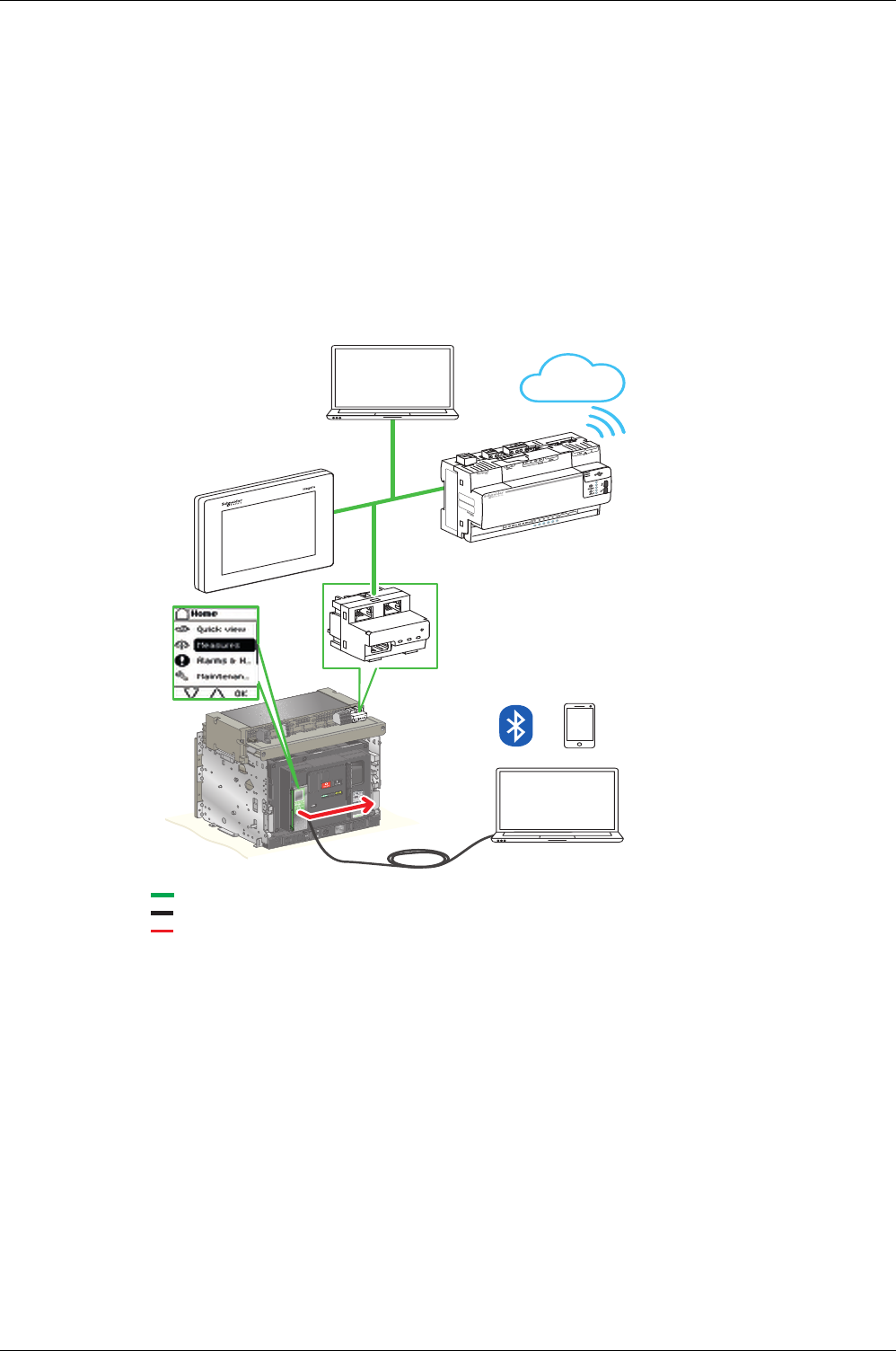
Micrologic X Control Units in Digital Systems
Presentation
Masterpact circuit breakers with Micrologic X control unit, in conjunction with Enerlin’X, provide simple and
reliable access to data from a smart panel or PC.
The following communication channels are offered:
Ethernet through IFE or EIFE
Masterpact MTZ mobile App through Bluetooth or NFC
Ecoreach software through USB port
Internet through Com’X through Ethernet
Micrologic X Control Units in Digital Systems
The following diagram shows how Micrologic X control units communicate within a digital system:
Ethernet
USB
Wireless communication
n
n
Internet
POWER
POWER
Com’X 200
POWER
100-230V
Introduction to the Micrologic X Control Unit
DOCA0102EN-00 05/2016 19
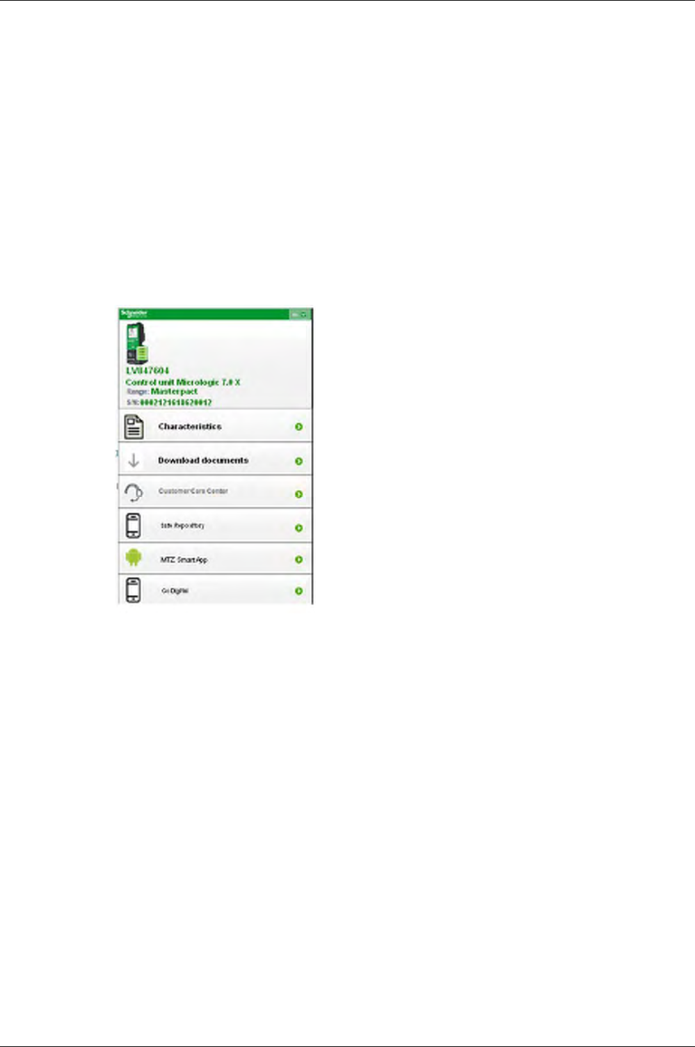
Go2SE Landing Page
Presentation
When the QR code on the front face of a Micrologic X control unit is flashed by using a smartphone running
a QR code reader, a landing page is displayed. The landing page displays some basic information about
the device in a header and a list of menus.
Header
The header displays the following information:
The product reference of the Micrologic X control unit
The type of control unit
The range of associated circuit breaker
The unique serial number of the Micrologic X control unit
Landing Page Menus
Characteristics
Selecting this menu gives access to a product datasheet which gives detailed information about the
product.
Download Documents
Selecting this menu gives access to the following documents:
Micrologic X Control Unit - User Guide
Masterpact MTZ1 Circuit Breakers and Switch-Disconnectors - User Guide
Masterpact MTZ2/MTZ3 Circuit Breakers and Switch-Disconnectors - User Guide
Download Customer Care Application
The customer care application for Android smartphones can be downloaded by following the link.
Safe Repository Access
Download Masterpact MTZ mobile App
Selecting this menu gives access to the smartphone application or the possibility to purchase/install it.
GoDigital
Selecting this menu gives direct access to the GoDigital marketplace webpage
(see page 20)
.
The landing page displays the following list of menus:
Characteristics
Download documents related to Masterpact and
Micrologic X devices
Customer Care Center
Safe Repository
Masterpact MTZ mobile App
GoDigital

Introduction to the Micrologic X Control Unit
20 DOCA0102EN-00 05/2016
GoDigital
GoDigital Marketplace
GoDigital is a marketplace to enable users to purchase and download Digital Modules to extend the
performance of Micrologic X control units.
Prerequisites
The following list indicates the necessary prerequisites for purchasing optional Digital Modules:
Unique Schneider Electric account with user name and password
Validated CRM internal user account to enable purchase of Digital Modules
Creation of a buyer account in GoDigital
Connection to a single Micrologic X control unit to read its unique serial number (see below)
Accessing GoDigital
You can access GoDigital using one of the following means:
From Ecoreach software either with a PC connected to a Micrologic X control unit or by selecting one
Micrologic X control unit (or project) from the software. Ecoreach reads the unique serial number of the
Micrologic X control unit, proposes available Digital Modules and gives direct access to the GoDigital
site.
Through the Masterpact MTZ mobile App, after connection to one Micrologic X control unit through
Bluetooth or NFC. A direct link gives access to the GoDigital webpage for mobile devices.
By flashing the QR code on the front face of the Micrologic X control unit from a smartphone. A landing
page opens and a direct link to GoDigital is proposed.
Directly to the GoDigital website (
http://godigital.schneider-electric.com/
). This access can only be used
to purchase Digital Modules for a second order for the same Micrologic X control unit using the serial
number listed in the My Asset tab.
Purchasing in GoDigital
After accessing the GoDigital website through one of the access points described in the previous
paragraph, follow this procedure to purchase Digital Modules:
Useful Information
The following points provide additional information on the use of GoDigital:
In Ecoreach software, Digital Modules can be selected from a list available for the unique serial number
of the selected Micrologic X control unit. Clicking on Buy gives direct access to the list of Digital Modules
in the GoDigital marketplace. The Digital Modules selected in Ecoreach are already checked.
To buy Digital Modules for more than one Micrologic X control unit, save the cart, select the serial
number of another control unit, and repeat step 2 in the procedure.
Step Action
1 Log in to the GoDigital website
NOTE: If user is unknown, a link to create a new account is proposed. If the user is recognized but no
buyer account exists in GoDigital, a link to create this account is proposed.
2 Choose Digital Modules required and add to cart. The cart can be saved for future validation and
purchase.
3 Submit the cart. The purchase is validated and the invoice, order confirmation and a link to the delivery
package are sent by email.
4 Click the link in the email to download the delivery package to a PC.
Introduction to the Micrologic X Control Unit
DOCA0102EN-00 05/2016 21
Installing and Removing Optional Digital Modules
Presentation
Once a Digital Module has been purchased in the GoDigital marketplace it can be installed in the
associated Micrologic X control unit using Ecoreach software.
Prerequisites
The following conditions must be met to install a Digital Module:
The Digital Module purchased in the GoDigital marketplace
The Digital Module delivery package downloaded onto a PC
The PC with Ecoreach software connected by a USB cable to the Micrologic X control unit to recognize
its serial number and ID
Installing a Digital Module
Follow this procedure to install purchased Digital Modules on a Micrologic X control unit:
Removing a Digital Module
Follow this procedure to remove a Digital Module from a Micrologic X control unit:
Predefined Events
The following events are generated when a Digital Module is installed or removed:
Step Action
1 Connect a PC running Ecoreach software directly to the mini USB port on the front of the Micrologic X
control unit.
2 Click the Connect device button to establish a connection between Ecoreach and the Micrologic X
control unit. Ecoreach displays the Micrologic X control unit serial number on the screen.
3 Select Digital Modules.
4 Check that the delivery package for the Digital Module to be installed is present on the PC being used.
5 Choose Digital Modules to be installed by clicking Install.
NOTE: Only modules that have been purchased previously can be installed directly by clicking Install.
6 When installation is completed and before unplugging the PC, disconnect Ecoreach from the device by
clicking the Disconnect button.
Step Action
1 Connect a PC running Ecoreach software directly to the mini USB port on the front of the Micrologic X
control unit.
2 Click the Connect device button to establish a connection between Ecoreach and the Micrologic X
control unit. Ecoreach displays the Micrologic X control unit serial number on the screen.
3 Select Digital Modules.
4 Choose Digital Modules to be removed by clicking Remove.
5 When removal is completed and before unplugging the PC, disconnect Ecoreach from the device by
clicking the Disconnect button.
User message History Severity
License installed Configuration Low
License uninstalled Configuration Low

Introduction to the Micrologic X Control Unit
22 DOCA0102EN-00 05/2016
Micrologic X Date and Time
Presentation
Micrologic X date and time are used for time stamping events to provide a temporal order.
Setting the Date and Time Manually
Micrologic X date and time can be set manually:
On Micrologic X display screen at Home → Configuration → General → Date & Time. The first
component of the date is day (dd) and the second component is month (mm).
With Ecoreach software
With Masterpact MTZ mobile App
Synchronizing the Date and Time Automatically
Micrologic X date and time can be automatically synchronized with the date and time of a smartphone,
using the Masterpact MTZ mobile App.
Micrologic X date and time can be automatically updated with the IFE or EIFE Ethernet interface with the
following conditions:
Ethernet interface is configured in SNTP mode
Ethernet interface receives an update date and time request (from Ecoreach software or a web browser
connected to the Ethernet interface webpage or third-party software)
NOTE: If the Micrologic X control unit is connected to an Ethernet interface configured in SNTP mode,
manual update of the Micrologic X date and time is possible but is immediately replaced by the date and
time of the IFE Ethernet interface.
Predefined Events
Setting the date and time generates the following low-severity event, which is logged in the Configuration
history: Clock setup
Introduction to the Micrologic X Control Unit
DOCA0102EN-00 05/2016 23
Micrologic X Power Supply
Internal and External Power Supplies
The Micrologic X control unit is powered by the current through internal current transformers (CT). Different
optional power supplies can also be used. The following list indicates the possible permanent power
supplies:
Internal voltage power supply (VPS) module, up to 600 Vac
External 24 Vdc power supply module with or without battery module (battery life 4 hours)
The following temporary power supplies can be used to power the control unit when other supplies are
unavailable. They provide access to all functions of the Micrologic X control unit:
PC through USB connection
External Mobile Power Pack through USB connection
During operation, when the load current is higher than 20% of the rated current, the internal current supply
ensures full functioning of the control unit and all protection functions, including long-time overcurrent
protection, short-time overcurrent protection, instantaneous overcurrent protection, and ground-fault
protection.
When the circuit breaker is not powered, an alternative power supply is necessary. More details are given
in the following presentation of each power supply.
An external 24 Vdc power supply is necessary to power IFE and EIFE Ethernet interfaces, and IO modules
(ULP).
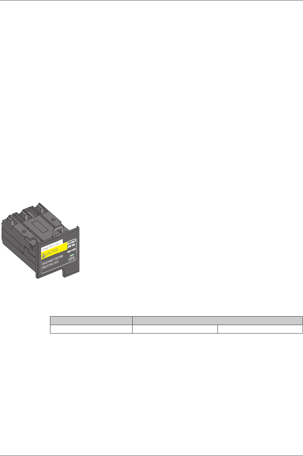
Voltage Power Supply (VPS) Module
The VPS module is optional for Micrologic 2.0 X, 5.0 X, and 6.0 X. It is installed as standard on
Micrologic 7.0 X to maintain earth-leakage protection.
A green LED on the front face indicates that the VPS module is powered and a 24 Vdc output is supplied.
Characteristics of the VPS module:
The internal voltage power supply (VPS) module for Micrologic X control unit powers the
main functions of the control unit, including the display screen, keypad, and wireless
communication, in the following circumstances:
When the circuit breaker is in low load conditions (< 20% In)
When there is no load but the circuit breaker is supplied with power, for example, there
is a tri-phase or bi-phase power voltage available downstream of the circuit breaker
The VPS module is installed in the lower part of the Micrologic X control unit.
Power supply Values
Input Vac 50/60 Hz Three phase 208–600 V +10 / –30%
Introduction to the Micrologic X Control Unit
24 DOCA0102EN-00 05/2016
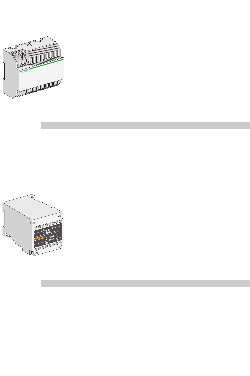
External 24 Vdc Power Supply (ABL8) Module
External 24 Vdc Power Supply (AD) Module
Characteristics of the AD module:
Battery Module
Characteristics of the battery module:
PC Power Supply
A PC provides a temporary power supply which can be used when the circuit breaker is not powered, and
during periods of setting, commissioning, testing, and maintenance.
It is connected by using a USB cable connected to the mini USB port on the Micrologic X control unit.
The 24 Vdc power supply module (with or without battery module) maintains the operation
of all functions of the Micrologic X control unit when the circuit breaker is open and not
energized.
The 24 Vdc power supply module maintains the functions of the Micrologic X control unit in
low load conditions (load below 20%).
The 24 Vdc power supply module provides a power supply during periods of setting,
commissioning, testing, and maintenance.
The 24 Vdc power supply module is mandatory to supply power to the IFE/EIFE Ethernet
interfaces and IO modules, when these are present.
Characteristic Values
Power supply 110/130, 200/240, 380/415 Vac, 50/60 Hz (+10%, –15%)
24/30, 48/60, 100/125 Vdc (+20% –20%)
Output voltage 24/30, 48/60, 100/125 Vdc (+20% -20%)
Ripple < 1%
Dielectric withstand 3.5 kV rms between input/output, for 1 minute
Overvoltage category Defined by IEC 60947-1 cat. 4
The battery module maintains the operation of the Micrologic X display screen and keypad if the
power supply is interrupted. It also enables wireless communication. It is installed in series
between the control unit and the 24 Vdc power supply module.
The battery module is a lithium type battery, with a service life of approximately ten years. If there
is no power supply to the 24 Vdc power supply module, the battery module provides power to the
control unit for four hours.
Characteristic Values
Battery run-time 4 hours
Mounting Vertical backplate or symmetrical rail

Introduction to the Micrologic X Control Unit
DOCA0102EN-00 05/2016 25
Mobile Power Pack
Check the charge level of the Power Pack by pressing the test button for one second. The indicator on the
Power Pack lights up to indicate the remaining charge.
Internal Battery
When no other power supply is supplying the Micrologic X control unit, the internal battery powers:
The trip cause LEDs
The red service LED
The Micrologic internal clock (date and time)
The internal battery of the Micrologic X control unit can be replaced on site when discharged.
The Mobile Power Pack is an external battery that enables power to be
supplied temporarily to the Micrologic X control unit.
The Mobile Power Pack enables use of the Micrologic X display screen and
keypad for basic setting and displaying when the power supply to the
Micrologic X control unit is interrupted.
The external Mobile Power Pack can be connected by using a USB cable
connected to the mini USB port on the Micrologic X control unit.
5Vc2.4A 5Vc1.5A 5Vc1A

Introduction to the Micrologic X Control Unit
26 DOCA0102EN-00 05/2016

DOCA0102EN-00 05/2016 27
Micrologic X
Using Micr ologic X C ontrol Units
DOCA0 102EN-00 05/2016
Using Micrologic X Control Units
Chapter 2
Using Micrologic X Control Units
What Is in This Chapter?
This chapter contains the following sections:
Section Topic Page
2.1 Presentation of HMIs 28
2.2 Using the Micrologic X HMI 31

Using Micrologic X Control Units
28 DOCA0102EN-00 05/2016
Pre senta tion o f HMIs
Section 2.1
Presentation of HMIs
What Is in This Section?
This section contains the following topics:
Topic Page
Micrologic X HMIs 29
Functions per HMI 30

Using Micrologic X Control Units
DOCA0102EN-00 05/2016 29
Micrologic X HMIs
Introduction
HMI from the following products can be used to communicate with the Micrologic X control unit:
Micrologic X display screen
Masterpact MTZ mobile App (Wireless NFC or Bluetooth)
Ecoreach software (USB connection and remote LAN connection))
FDM128
Webpages on IFE/EIFE server

Using Micrologic X Control Units
30 DOCA0102EN-00 05/2016
Functions per HMI
Introduction
List of functions available according to the HMI:
All features on Ecoreach software
A wide selection of features on Masterpact MTZ mobile App
Essential features on the Micrologic X display screen
FDM128
Webpages on IFE/EIFE server

Using Micrologic X Control Units
DOCA0102EN-00 05/2016 31
Using the M icrologic X H MI
Section 2.2
Using the Micrologic X HMI
What Is in This Section?
This section contains the following topics:
Topic Page
Micrologic X HMI Description 32
HMI Display Modes 34
Quick View Mode 35
Tree Navigation Mode 38
Measures Menu 45
Alarms & History Menu 50
Maintenance Menu 51
Configuration Menu 52
Protection Menu 54
Pop-up Event Messages 57
Using Micrologic X Control Units
32 DOCA0102EN-00 05/2016
Micrologic X HMI Description
Introduction
The human machine interface (HMI) of the Micrologic X control unit includes:
A graphic display screen with colored backlight
Buttons to navigate through the menu structure, and access monitored parameters and configuration
settings
Display Screen and Buttons
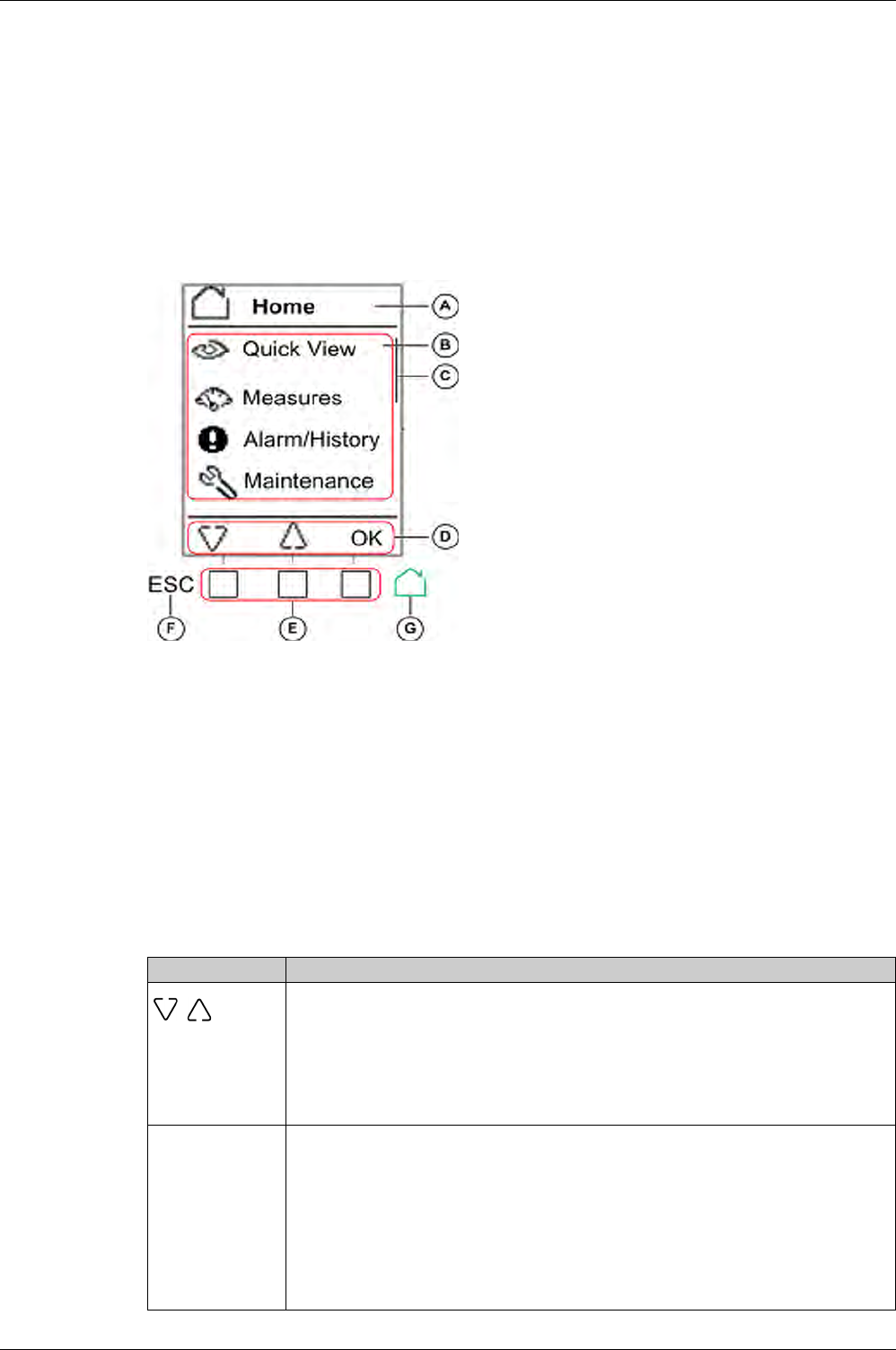
The Micrologic X control unit includes the following display screen with contextual and dedicated buttons:
Button Functional Types
Use the buttons beneath the display screen to:
Navigate the menu structure
Display monitored values
Access and edit configuration settings
The control unit provides the following types of buttons:
Contextual buttons: each screen can have up to three contextual buttons. The function of each button
is determined by an icon located on the display screen directly above it.
Dedicated buttons, that perform the escape and home functions.
Contextual Buttons
A Screen name
B Functional screen content
C Scroll bar indicating the relative position of the
items in a list larger than the display screen
D Context-specific function icons
E Contextual buttons that perform the context-
specific function described by the icon
immediately above each button
F Escape button, used to return to the previous
screen and/or trigger a data saving confirmation
screen
G Home button, used to jump to the Home screen
and/or trigger a data saving confirmation screen
Icon displayed Description
Use the up and down buttons to move between:
Screen names within the same level of menu hierarchy
List items
The up and down arrows do not support looping back. At a terminus of a menu structure or item
list, either the up or down arrow is no longer displayed (depending on whether the terminus is
the beginning or end of the list). The up and down navigation behavior is the same for all menus
and lists.
OK Use the OK button:
To validate a selection
To navigate from the level currently displayed in the hierarchy to the selected sublevel
immediately below it. In this way, navigation is possible from:
The active menu to the immediate submenu
A submenu to a monitored item or configuration parameter
A monitored item to its monitored value
A configuration parameter to its configuration setting
To view details and acknowledge an event pop-up screen or error code
Using Micrologic X Control Units
DOCA0102EN-00 05/2016 33
Dedicated Buttons
Display Screen Backlight
The backlight color and intensity depends on the operating state of the control unit, as follows:
NOTE: When Quick View scrolling is off, the backlight changes from high intensity to low intensity when in
standby. High intensity resumes when a button is pressed.
Display Screen Language
To change the display screen language go to:
Home → Configuration → General → Language
Selections include:
Deutsch
English(US)
Español
Français
Italiano
Português
English(UK)
Y
N
Use the Y (Yes) and N (No) buttons to acknowledge actions, for example, when a confirmation
screen is displayed.
+
–
Use the + and – buttons to increment or decrement a configuration setting, either numerical
values or predefined list items.
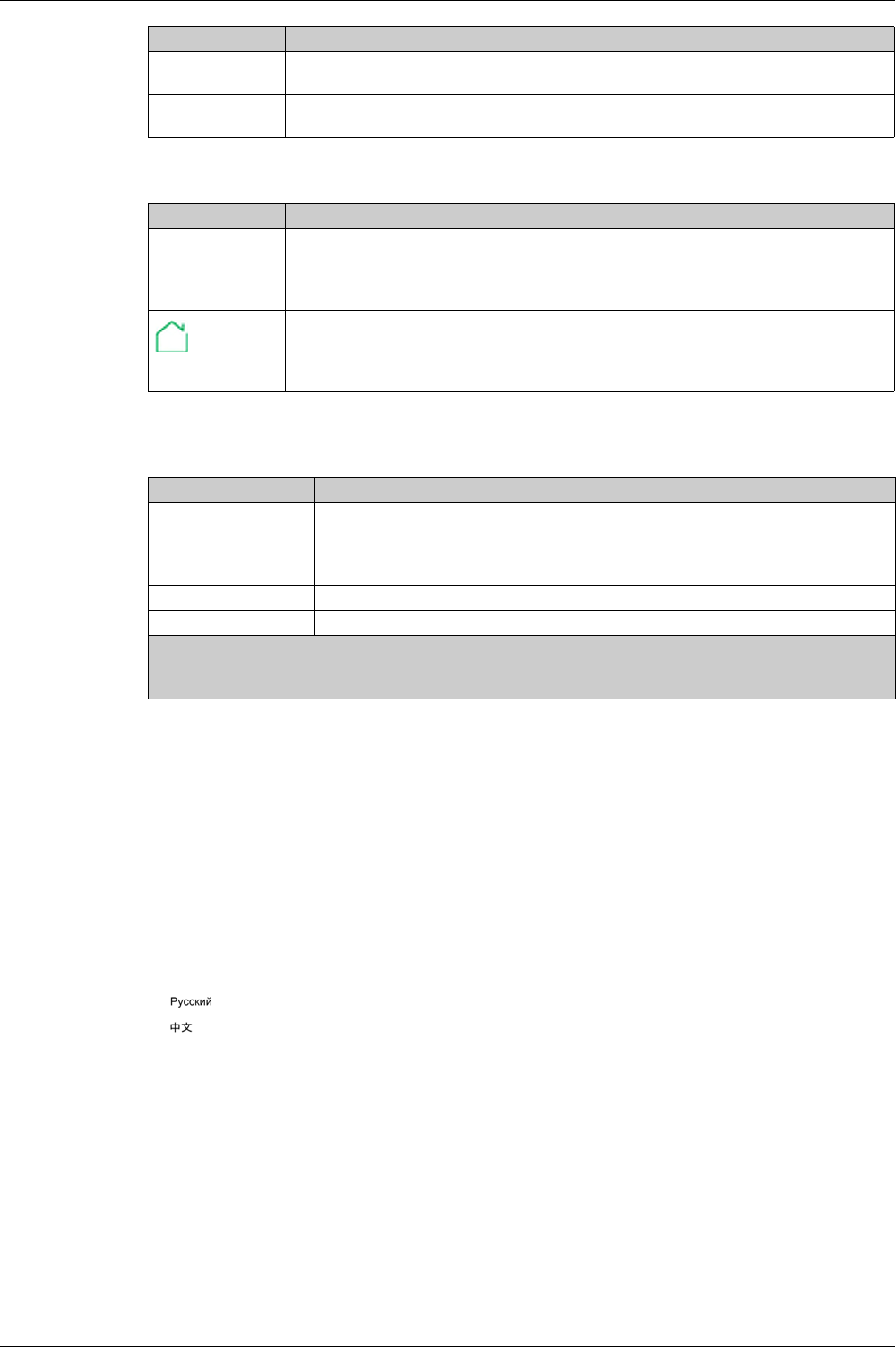
Icon displayed Description
Icon displayed Description
ESC Use the ESC (escape) button to:
Navigate from the level currently displayed in the hierarchy to the level immediately above
Save a change to a configuration setting. A confirmation screen pops up and must be
acknowledged before returning to the menu on the level above.
Use the home button to:
Return to the Home screen
Save a change to a configuration setting. A confirmation screen pops up and must be
acknowledged before returning to the home screen.
Backlight color Control unit operating state
White1Quick View scrolling is enabled and running
Tree navigation mode is enabled for navigating among menus in display screens
Bluetooth wireless communication is enabled and the Bluetooth pairing message is
displayed.
Red A trip or a high severity event message is displayed.
Orange A medium severity alarm message is displayed, and no trip or high severity alarm is active.
1 The backlight of the Health screen in Quick View is
Red if a high severity event is active.
Orange if a medium severity event is active.

Using Micrologic X Control Units
34 DOCA0102EN-00 05/2016
HMI Display Modes
Presentation
The Micrologic X control unit HMI supports the following display modes:
Quick View mode to display a selection of data
Tree Navigation mode to access all data through a menu structure
NOTE: Both Quick View and Tree Navigation display modes are overridden by event messages
(see page 57)
.
Quick View Mode
Quick View is the default HMI display mode. It displays a selection of data screens.
When Quick View scrolling is enabled, the screens are displayed automatically one after the other with a
configurable time delay.
When Quick View scrolling is disabled the Quick View screens are viewable in the Quick View menu,
accessed from the Home menu.
Tree Navigation Mode
In Tree Navigation display mode, use the contextual buttons to navigate in the menu structure. Tree
Navigation display mode presents a single network of menus, with monitoring values and editable
configuration settings.
Tree navigation is always accessible from Quick View screens by pressing the Home button.
Refer to the Micrologic X local HMI description
(see page 32)
for information on how to use the HMI buttons
to:
Navigate the menu structure
Access and edit settings
Using Micrologic X Control Units
DOCA0102EN-00 05/2016 35
Quick View Mode
Quick View
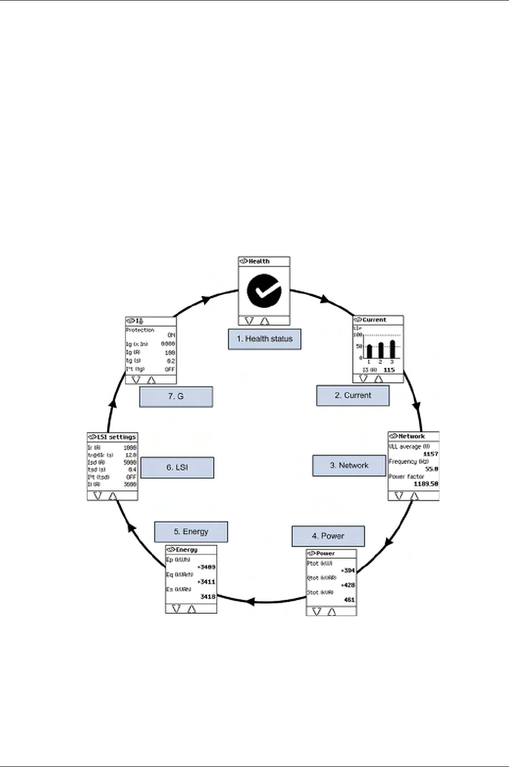
Quick View presents a sequence of screens, depending on the type of Micrologic X control unit. Each
screen displays a snapshot of operating values for the control unit.
With automatic scrolling enabled, the screens are displayed in sequence with a configurable time delay.
With automatic scrolling disabled, the screens can be navigated manually.
Quick View scrolling is enabled as the factory setting.
When the Micrologic X control unit is switched on, Quick View scrolling begins after the configured time-
out if there are no active event messages
Configure the Quick View display mode by setting:
The display time for each screen in the Quick View scrolling sequence.
The time delay for automatically resuming scrolling, after scrolling has been interrupted.
If scrolling is off, the current bar graph is displayed after this time delay.
The following is an example of the Quick View screens for the Micrologic 6.0 X control unit, with dual
settings disabled.

Using Micrologic X Control Units
36 DOCA0102EN-00 05/2016
List of Quick View Screens
Depending on the type of the Micrologic X control unit, Quick View mode displays the following screens:
Configuring Quick View Mode
To configure Quick View settings, go to Home → Configuration → General → Quick View. The following
settings are available:
Scrolling: Set this to ON to enable automatic scrolling in Quick View. (When OFF is selected, the current
bar graph screen is displayed after the configured timeout.)
When Quick View scrolling is enabled the following settings are available:
Pageflow: The length of time each Quick View screen is displayed while scrolling.
Auto start: The time delay before Quick View scrolling resumes after an interruption. This time delay is
also the event timeout, which is the time delay before an event message is displayed again if the event
cause is not acknowledged by pressing OK.
When Quick View scrolling is disabled the following setting is available:
Screen Description Micrologic X type
Health1Displays the health of the circuit breaker:
OK (white)
Alarm - medium-level (orange)
Alarm - high-level (red)
Micrologic 2.0 X,
5.0 X, 6.0 X, 7.0 X
Current1Displays I1, I2, I3 RMS current on phase 1, 2, 3 values as bar graphs
expressed in % of Ir.The highest phase current value is displayed in A (Amps)
under the bar graph.
Micrologic 2.0 X,
5.0 X, 6.0 X, 7.0 X
Network1Displays real-time values for:
Average of 3 RMS phase-to-phase voltage
Frequency
Power factor
Micrologic 2.0 X,
5.0 X, 6.0 X, 7.0 X
Power1Displays real time values for:
P tot: total active power
Q tot: total reactive power
S tot: total apparent power
Micrologic 2.0 X,
5.0 X, 6.0 X, 7.0 X
Energy1Displays real time values for:
Ep: total active energy
Eq: total reactive energy
Es: total apparent energy
Micrologic 2.0 X,
5.0 X, 6.0 X, 7.0 X
Trip curve Indicates, when dual setting is on:
A curve activated or
B curve activated
NOTE: The screen is not displayed when dual setting is off.
Micrologic 2.0 X,
5.0 X, 6.0 X, 7.0 X
LI Displays a selection of protection settings:
Long time overcurrent protection threshold Ir
Long time overcurrent protection time delay tr
Short time overcurrent protection threshold Isd
Micrologic 2.0 X
LSI Displays a selection of protection settings:
Long time overcurrent protection threshold Ir
Long time overcurrent protection time delay tr
Short time overcurrent protection threshold Isd
Short time overcurrent protection time delay tsd
Instantaneous overcurrent protection threshold Ii
Micrologic 5.0 X,
6.0 X, 7.0 X
GDisplays a selection of protection settings:
Ground fault protection threshold Ig
Ground fault protection time delay tg
Micrologic 6.0 X
VDisplays a selection of protection settings:
Earth fault protection threshold IΔn
Earth fault protection time delay tΔn
Micrologic 7.0 X
1 Screen data is refreshed every second.
Using Micrologic X Control Units
DOCA0102EN-00 05/2016 37
Time out: The time delay before the current bar graph is displayed. This time delay is also the event
timeout, which is the time delay before an event message is displayed again if the event cause is not
acknowledged by pressing OK.
The configurable settings are shown in the following table.
Starting Quick View Scrolling
With Quick View mode enabled, resume Quick View scrolling:
automatically
manually
To begin Quick View scrolling automatically, wait for the Auto start timeout to elapse.
To begin Quick View scrolling manually:
Stopping Quick View Scrolling
Stop Quick View scrolling as follows:
Press the ESC or home button. The display screen displays the Home menu. From here, use the up
and down buttons to navigate through the menu structure.
NOTE: If no button is pressed before the Auto start timeout expires, Quick View scrolling resumes.
Press one of the three contextual buttons. Quick View scrolling stops. Use the up and down buttons to
scroll manually through the Quick View screens.
Disabling Quick View Automatic Scrolling
To disable scrolling in Quick View mode:
Setting Unit Range Step Factory Setting
Scrolling – ON/OFF – ON
Pageflow seconds 3–60 1 3
Auto start minutes 1–60 1 15
Time out minutes 1–60 1 15
Step Action
1 In the Home menu, select Quick View.
2Press OK to resume Quick View scrolling.
Step Action
1 Press the Home button.
2 Navigate to Home → Configuration → General → Quick View.
3 Press OK.
4 Use the + or - contextual buttons to set the Scrolling setting to:
ON to select Quick View automatic scrolling.
OFF to disable Quick View automatic scrolling.
5 Press OK to save the selection.
6 Press ESC or the Home button.
A confirmation screen is displayed.
7 Press Y to save the settings.
Using Micrologic X Control Units
38 DOCA0102EN-00 05/2016
Tree Navigation Mode
Tree Structure Screen Display
Use Tree Navigation mode to navigate manually through the Micrologic X control unit menu structure. Tree
Navigation mode enables the following actions:
Display measurement values for the control unit
View active alarms, and event history
View maintenance items, and a history of service records
Display and edit control unit configuration settings
Display and edit protection settings
All Tree Navigation menu selections begin at the home button:
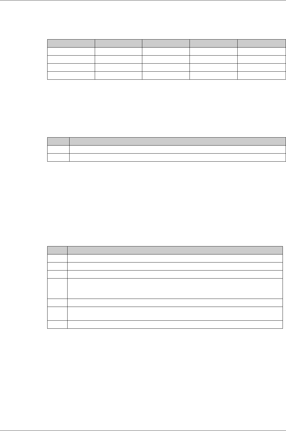
Display Screen Menus
The Micrologic X control unit presents data, commands, and settings in a tree structure. Click the link on
one of the following level 2 sub-menu items to see its content:
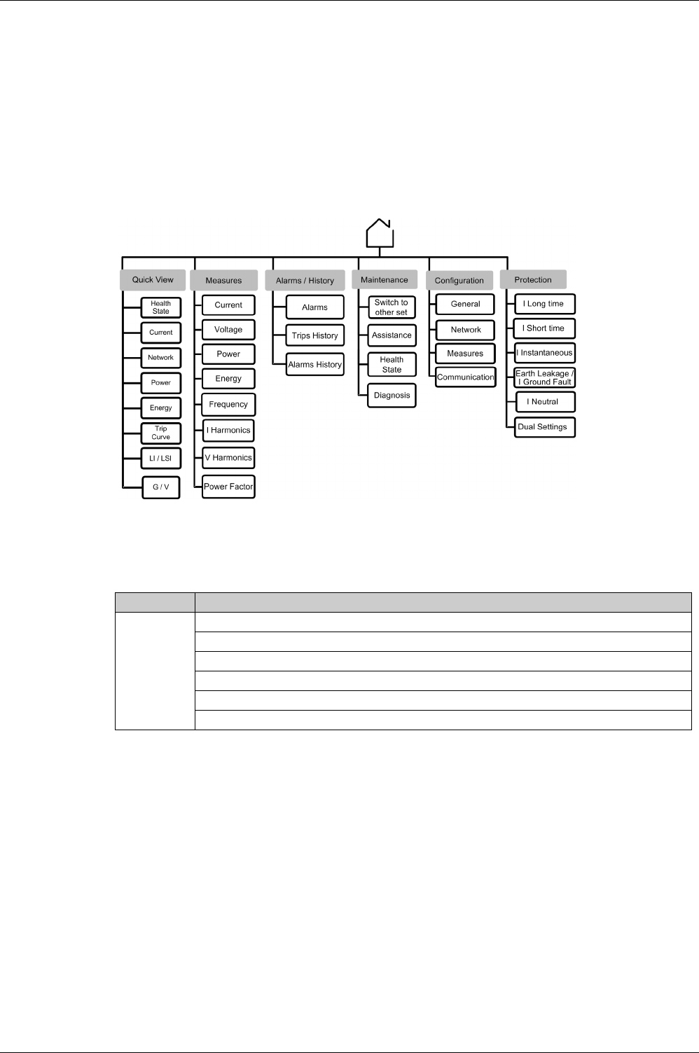
Measures Screens with Quality Gauge
A quality gauge is displayed on the following screens to give a graphical representation of the
measurement compared to the expected range:
3-phase current unbalances IUnb
Average of 3 rms phase-to-neutral voltages Vavg VLL(V)
Maximum of 3 rms phase-to-neutral voltage unbalances Vunb VLL(%)
Frequency F(Hz)
Level 1 Level 2
Home Quick View
(see page 35)
Measures
(see page 45)
Alarms/History
(see page 50)
Maintenance
(see page 51)
Configuration
(see page 52)
Protection
(see page 54)
Using Micrologic X Control Units
DOCA0102EN-00 05/2016 39
For example, for the frequency screen, the following icons indicate the measurement compared to the
expected range:
Navigating in the Menu Structure
Use the contextual and dedicated buttons on the face of the Micrologic X control unit to navigate in the
menu structure, and to access displayed values and configurable settings.
The possible operations are listed below, and are illustrated with an example:
Display data, for example, energy values
Reset values or counters, for example, reset the maximum RMS current
Select options in a list, for example, language
Edit a value, for example, nominal voltage
Set protection settings, for example, long-time overcurrent protection
Validate a pop-up message, for example, a pop-up trip message
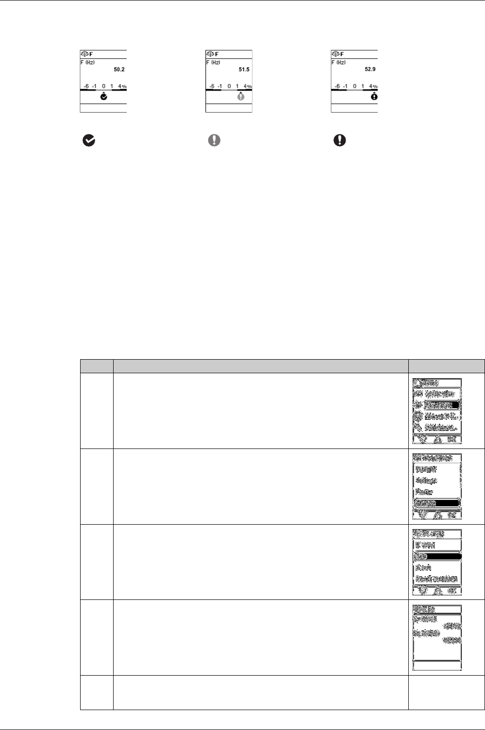
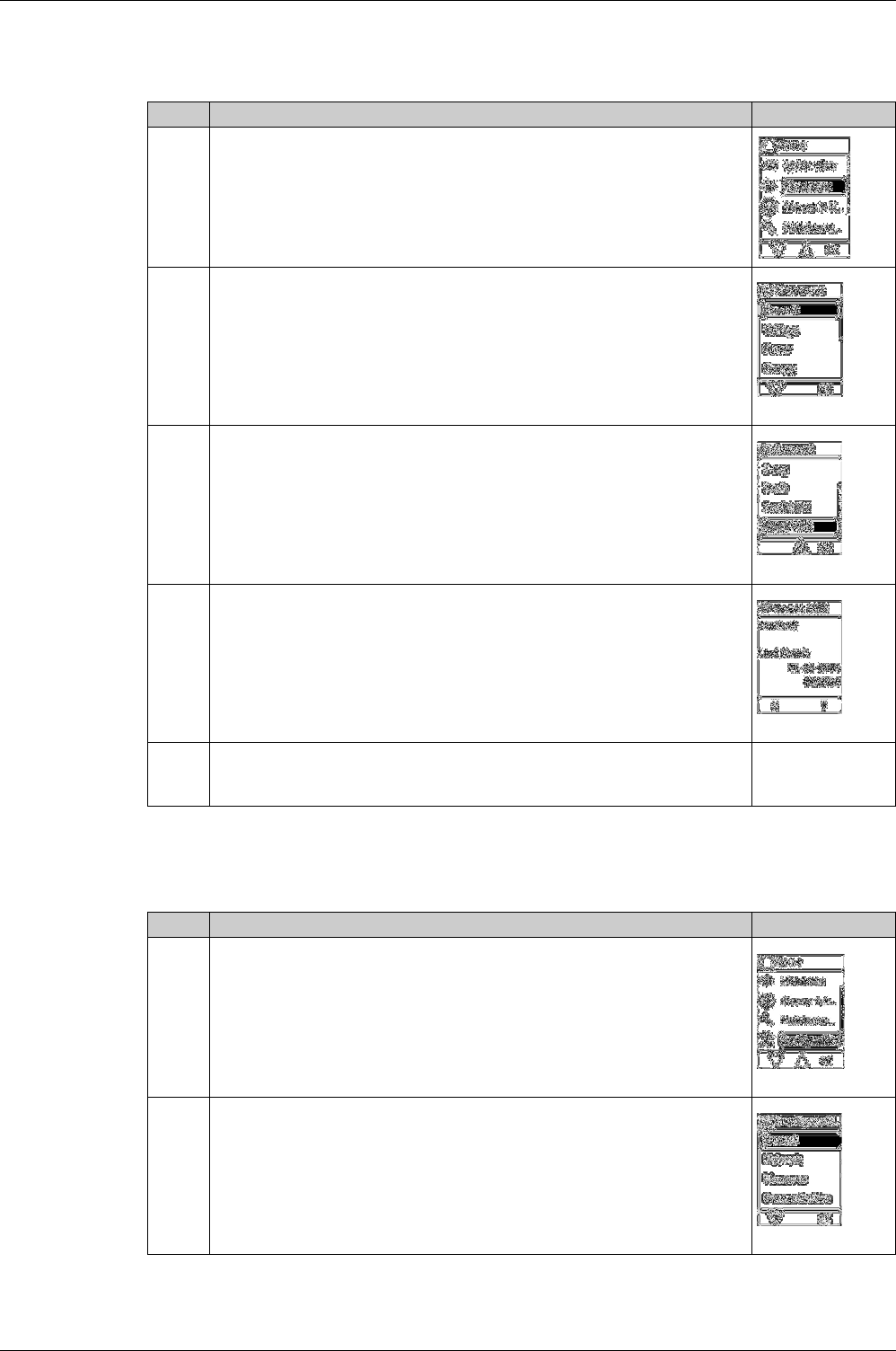
Displaying Data
The following example shows how to display energy values:
OK if the difference between
the measured and expected
frequencies is less than 1%
Medium-level alarm if the
difference between the measured
and expected frequencies is +1–
4% or -1– -6%
High-level alarm if the
difference between the measured
and expected frequencies is
greater than +4% or less than -6%
Step Action Screen
1 Press the home button. The Home menu opens. Press the down arrow to select
Measures.
2 Press OK. The Measures menu opens. Press the down arrow to select Energy.
3 Press OK. The Energy menu opens. Press the down arrow to select E in.
4 Press OK. The E in screen is displayed.
5 To exit the E in screen, either:
Press the home button to return to the Home menu.
Press the ESC button to return to the Energy menu.
Using Micrologic X Control Units
40 DOCA0102EN-00 05/2016
Resetting Values
Some menus present values or counters that can be reset. The following example shows how to navigate
to and reset the maximum RMS current:
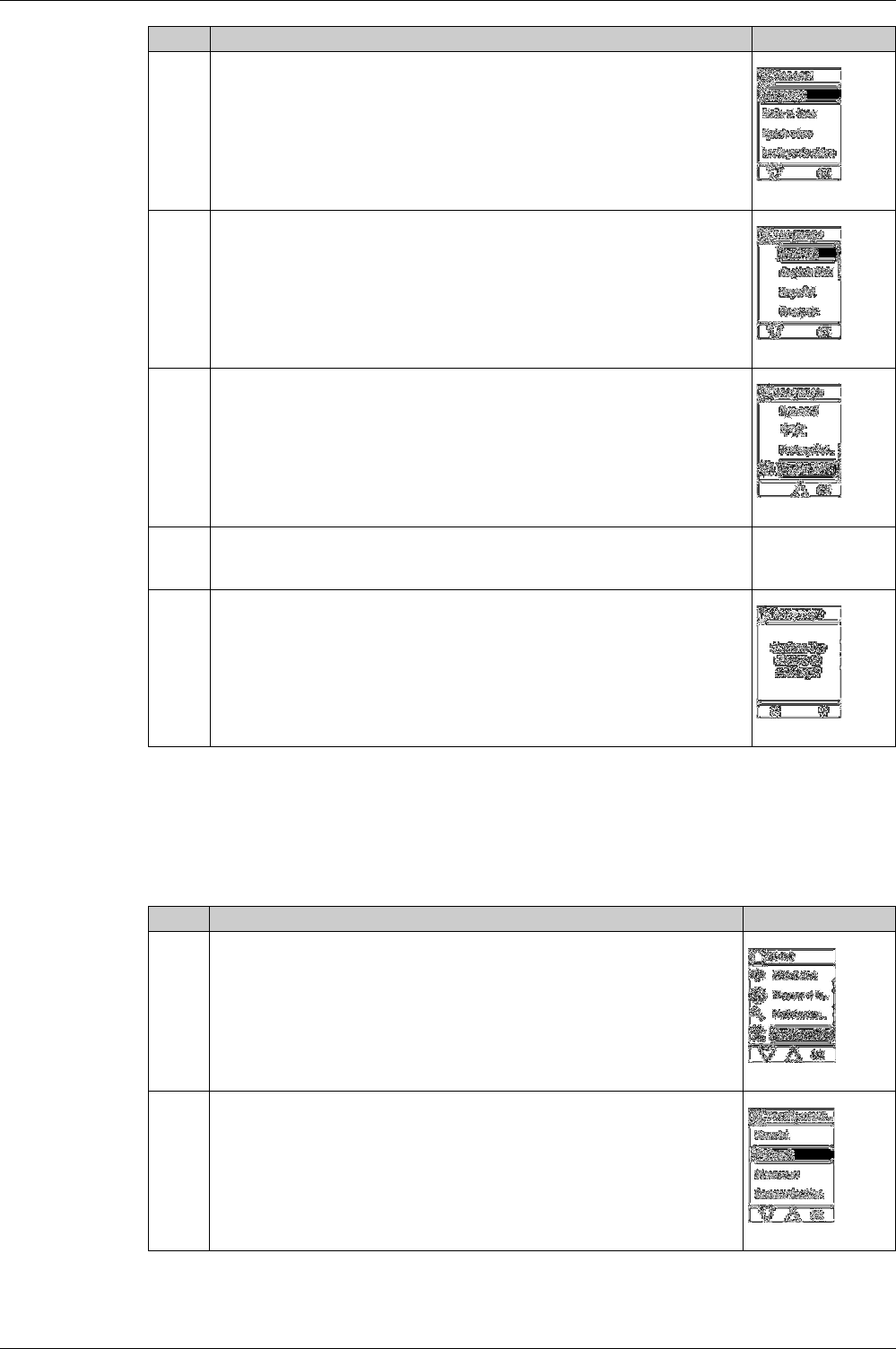
Selecting Options in a List
Some menus present options in a list. The following example shows how to navigate to and select
language options:
Step Action Screen
1 Press the home button. The Home menu opens. Press the down arrow to select
Measures.
2 Press OK. The Measures menu opens. Select Current.
3 Press OK. The Current menu opens. Press the down arrow to select Reset Max.
4 Press OK. The Reset Max confirmation screen opens.
5 Do one of the following:
Press Y to reset the maximum RMS current and return to the Current screen.
Press N to return to the Current screen without resetting the value.
Step Action Screen
1 Press the home button. The Home menu opens. Press the down arrow to select
Configuration.
2 Press OK. The Configuration menu opens. Select General.
Using Micrologic X Control Units
DOCA0102EN-00 05/2016 41
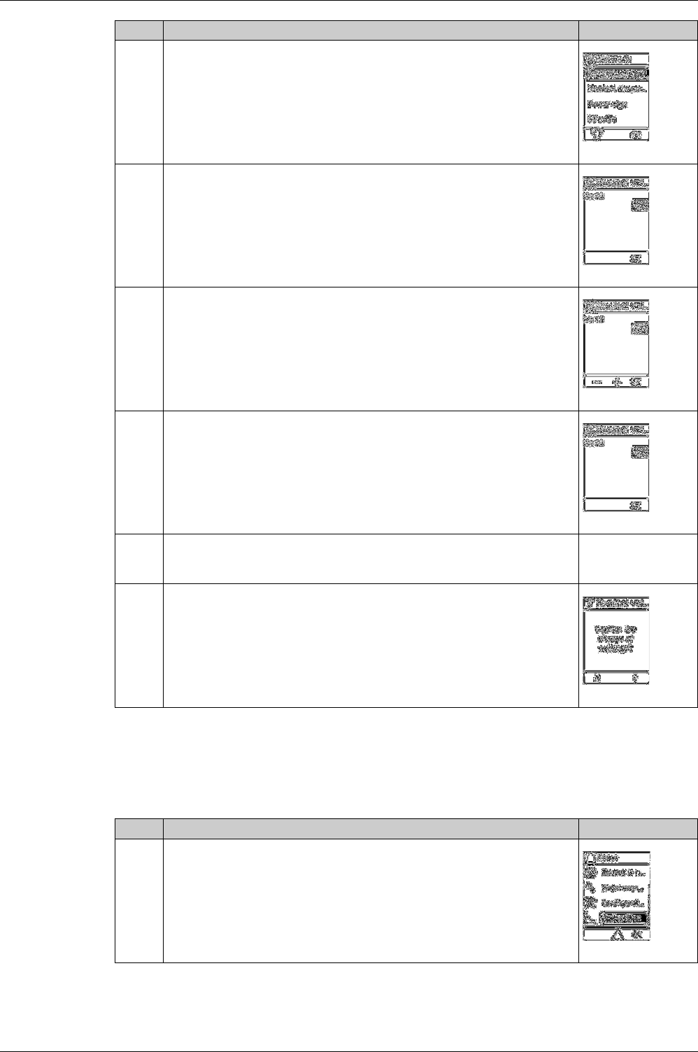
Editing and Saving Parameter Settings
When editing a parameter setting, use the + or – buttons to increment or decrement the setting by a single-
step amount. Hold down the button to accelerate the process.
This function applies to both numeric values and list selections.
The following example shows how to edit the nominal voltage:
3 Press OK. The General menu opens. Select Language
4 Press OK. The Language menu opens.
5 Press the up and down arrow buttons to select a language and press OK.A
confirmation check appears next to the selected language.
6 To save the selection, press:
The ESC button to return to the General menu.
The home button to return to the Home menu.
–
7 In the confirmation screen:
Press Y to confirm the change of settings.
Press N to undo the edit.
Step Action Screen
Step Action Screen
1 Press the home button. The Home menu opens. Press the down arrow to select
Configuration.
2 Press OK. The Configuration menu opens. Press the down arrow to select Network.
Using Micrologic X Control Units
42 DOCA0102EN-00 05/2016
If the edit did not succeed, a detected error message appears. Click OK to confirm the message, and then
the previous menu is displayed.
Setting Protection Settings
The following example shows how to set the long-time overcurrent protection:
3 Press OK. The Network menu opens. Select Nominal Voltage.
4 Press OK. The Nominal Voltage menu opens.
5 In the Nominal Voltage menu, select Un(V) and press OK to enable editing of the
Un(V) parameter. The parameter is displayed in black on a white background to
indicate that editing is enabled.
In this example, 400, the factory setting value, is displayed.
6 Press the + and – buttons to scroll through available settings.
Possible values are 208, 220, 230, 240, 380, 400, 415, 440, 480, 500, 525, 550,
575, 600, 660, 690, and 1,000.
Press OK to select a setting.
The background changes to black.
7 To save the change of settings, press one of the following:
The ESC button to return to the Nominal Voltage screen
The home button to return to the Home menu
–
8 In the confirmation screen:
Press Y to confirm and save the change of settings.
Press N to undo the edit.
Step Action Screen
Step Action Screen
1 Press the home button. The Home menu opens. Press the down arrow to select
Protection.
Using Micrologic X Control Units
DOCA0102EN-00 05/2016 43
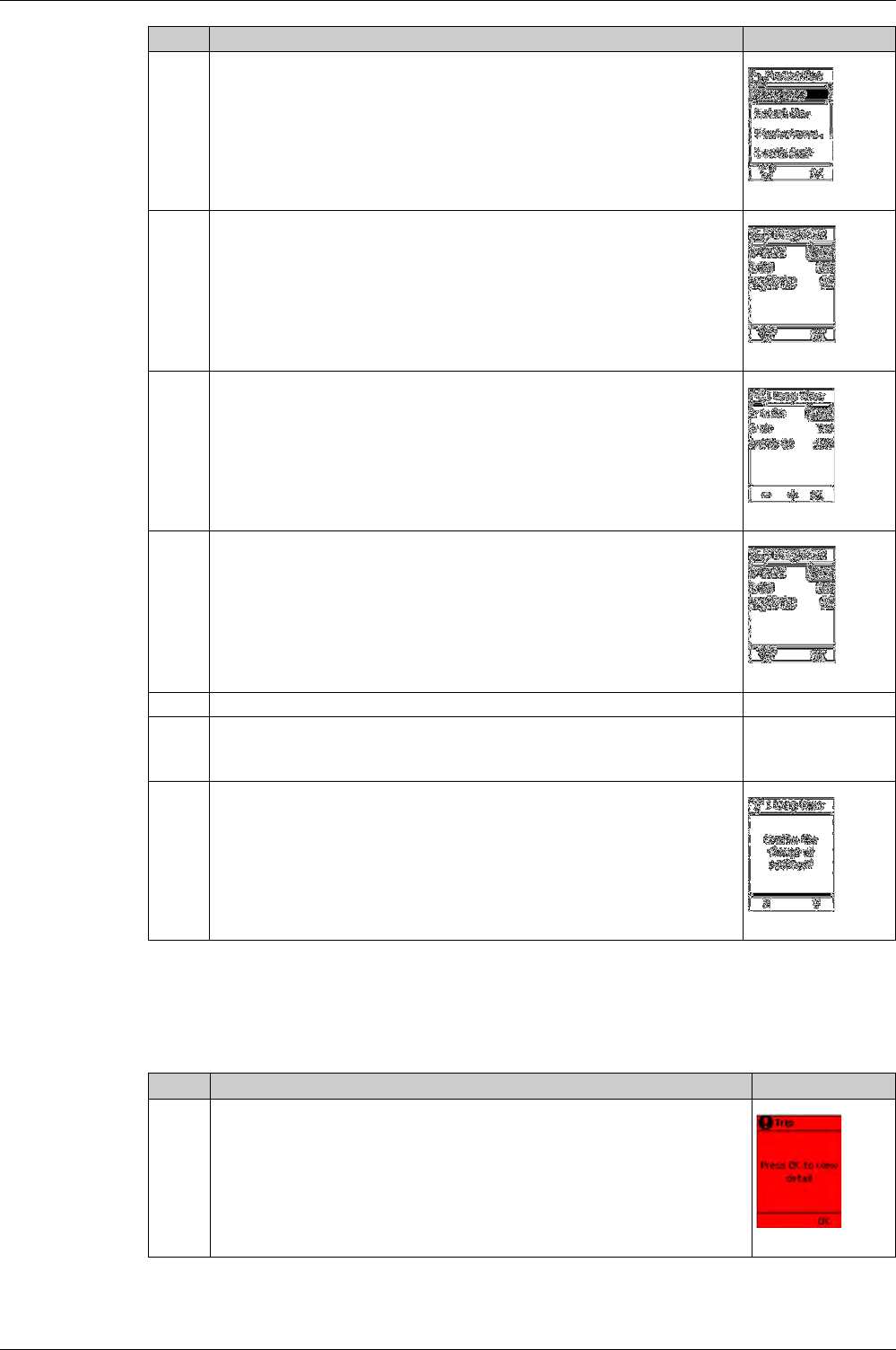
Validating a Pop-Up Message
A trip or alarm event displays a pop-up message on the display screen. The message overrides the screen
currently displayed.
The following example shows how to handle a pop-up trip message.
2 Press OK. The Protection menu opens. Select I Long time.
3 Press OK. The I Long time menu opens. In the I Long time menu, select the Ir
parameter.
4 Press OK to enable editing of the Ir parameter.
The parameter is displayed in black on a white background to indicate that editing
is enabled.
5 Press the + and – buttons to scroll through available settings.
Press OK to select a setting.
The parameter is displayed in white on a black background to indicate that a setting
has been selected.
6 Use the down arrow to select the next parameter to be set and repeat step 5.
7 To save the change of settings, press:
The ESC button to return to the Protection screen
The home button to return to the Home menu
–
8 In the confirmation screen:
Press Y to confirm and save the change of settings.
Press N to undo the edit.
Step Action Screen
Step Action Screen
1 A pop-up trip message appears on the screen.

Using Micrologic X Control Units
44 DOCA0102EN-00 05/2016
2 Press OK to view details of the trip.
3 If a down arrow appears at the bottom of the screen, press the down arrow to view
more details about the trip event.
4 After taking steps to resolve the cause of the trip, click OK to acknowledge the trip
context. The Alarm/History screen is displayed.
–
5 Press ESC to return to the screen displayed before the pop-up message appeared,
or Home to return to the Home screen.
Step Action Screen
Using Micrologic X Control Units
DOCA0102EN-00 05/2016 45
Measures Menu
Description
The Measures menu contains the following sub-menus:
Current
The Current menu presents the following measurements:
Level 1 Level 2 Level 3 Function description
Home Measures Current Current real-time measurements
Voltage Voltage real-time measurements
Power Power real-time measurements
Energy Energy real-time measurements
Frequency Frequency real-time measurements
I Harmonics Current harmonics real-time measurements
V Harmonics Voltage harmonics real-time measurements
Power Factor Power factor real-time measurement
Level 3 Level 4 Level 5 Parameter name
Current I I1 (A) RMS current on phase 1
I2 (A) RMS current on phase 2
I3 (A) RMS current on phase 3
IN (A)1RMS current on neutral
Ig (A)2RMS current on ground
IΔn (A)3RMS current on earth leakage
I MAX I1 (A) Maximum RMS current on phase 1
I2 (A) Maximum RMS current on phase 2
I3 (A) Maximum RMS current on phase 3
IN (A)1Maximum RMS current on neutral
Ig (A)2Maximum of RMS current on ground
IΔn (A)3Maximum of RMS current on earth leakage
I Avg I (1,2,3) (A) Average of 3-phase RMS currents
I Unb I (1,2,3) (%) 3-phase current unbalances, with quality gauge
I Unb MAX I (1,2,3) (%) Maximum of 3-phase current unbalances
Reset MAX Reset of maximum RMS current, plus date and time of
last reset
1 Applies to 4-pole circuit breakers or 3-pole circuit breakers with ENCT option.
2 Applies to Micrologic 2.0 X, 5.0 X, 6.0 X
3 Applies to Micrologic 7.0 X.
Using Micrologic X Control Units
46 DOCA0102EN-00 05/2016
Voltage
The Voltage menu presents the following measurements:
Level 3 Level 4 Level 5 Parameter name
Voltage V V12 (V) RMS phase-to-phase voltage 1-2
V23 (V) RMS phase-to-phase voltage 2-3
V31 (V) RMS phase-to-phase voltage 3-1
V1N (V)1RMS phase-to-neutral voltage 1-N
V2N (V)1RMS phase-to-neutral voltage 2-N
V3N (V)1RMS phase-to-neutral voltage 3-N
V MAX V12 (V) Maximum RMS phase-to-phase voltage 1-2
V23 (V) Maximum RMS phase-to-phase voltage 2-3
V31 (V) Maximum RMS phase-to-phase voltage 3-1
V1N (V)1Maximum RMS phase-to-neutral voltage 1-N
V2N (V)1Maximum RMS phase-to-neutral voltage 2-N
V3N (V)1Maximum RMS phase-to-neutral voltage 3-N
V MIN V12 (V) Minimum RMS phase-to-phase voltage 1-2
V23 (V) Minimum RMS phase-to-phase voltage 2-3
V31 (V) Minimum RMS phase-to-phase voltage 3-1
V1N (V)1Minimum RMS phase-to-neutral voltage 1-N
V2N (V)1Minimum RMS phase-to-neutral voltage 2-N
V3N (V)1Minimum RMS phase-to-neutral voltage 3-N
V Avg VLL (V) Average of 3 RMS phase-to-phase voltages
(V12+V23+V31)/3, with quality gauge
VLN (V)1Average of 3 RMS phase-to-neutral voltages
(V1N+V2N+V3N)/3
V Unb VLL (%) 3 phase-to-phase voltage unbalances, with quality
gauge
VLN (%)13 phase-to-neutral voltage unbalances
VUnb MAX VLL (%) Maximum V Unb VLL value since last reset
VLN (%)1Maximum V Unb VLN value since last reset
Reset MIN/MAX Reset of minimum and maximum RMS voltage, plus
date and time of last reset
1 Applies to 4-pole circuit breakers or 3-pole circuit breakers with ENVT option.
Using Micrologic X Control Units
DOCA0102EN-00 05/2016 47
Power
The Power menu presents the following measurements:
Energy
The Energy menu presents the following measurements:
Frequency
The Frequency menu presents the following measurements:
Level 3 Level 4 Level 5 Parameter name
Power P P1 (kW) Active power on phase 1
P2 (kW) Active power on phase 2
P3 (kW) Active power on phase 3
Ptot (kW) Total active power
P MAX Ptot (kW) Maximum total active power
QQ1 (kVAR)1Reactive power on phase 1
Q2 (kVAR)1Reactive power on phase 2
Q3 (kVAR)1Reactive power on phase 3
Qtot (kVAR) Total reactive power
Q MAX Qtot (kVAR) Maximum total reactive power
SS1 (kVA)1Apparent power on phase 1
S2 (kVA)1Apparent power on phase 2
S3 (kVA)1Apparent power on phase 3
Stot (kVA) Total apparent power
S MAX Stot (kVA) Maximum total apparent power
Reset MAX Reset of maximum power, plus date and time
of last reset
1 Applies to 4-pole circuit breakers or 3-pole circuit breakers with ENVT option.
Level 3 Level 4 Level 5 Parameter name
Energy E total Ep (kWh) Total active energy
Eq (kVArh) Total reactive energy
Es (kVAh) Total apparent energy
E received Ep (kWh) Total active energy delivered (counted positively)
Eq (kVArh) Total reactive energy delivered (counted positively)
E delivered Ep (kWh) Total active energy received (counted negatively)
Eq (kVArh) Total reactive energy received (counted negatively)
Reset counters Reset of accumulated energy, plus date and time of last
reset
Level 3 Level 4 Level 5 Parameter name
Frequency F F (Hz) Frequency, with quality gauge
F MAX F (Hz) Maximum frequency
F MIN F (Hz) Minimum frequency
Reset MIN/MAX Reset of minimum and maximum frequency, plus date and
time of last reset
Using Micrologic X Control Units
48 DOCA0102EN-00 05/2016
I Harmonics
The I Harmonics menu presents the following measurements:
V Harmonics
The V Harmonics menu presents the following measurements:
Level 3 Level 4 Level 5 Level 6 Parameter name
I Harmonics I THD I1 (%) Total Harmonic Distortion (THD) of current on phase
1 compared to the fundamental
I2 (%) Total Harmonic Distortion (THD) of current on phase
2 compared to the fundamental
I3 (%) Total Harmonic Distortion (THD) of current on phase
3 compared to the fundamental
IN (%)1Total Harmonic Distortion (THD) of current on neutral
compared to the fundamental
I THD IN MAX1IN (%) Maximum of Total Harmonic Distortion (THD) of
current on neutral compared to the fundamental
I THD Avg I (1, 2, 3)% Average of 3 phase current Total Harmonic
Distortions (THD) compared to the fundamental
I THD Avg MAX I (1, 2, 3)% Maximum average of 3 phase current Total Harmonic
Distortions (THD) compared to the fundamental, plus
date and time of occurrence
Reset MAX Reset of minimum and maximum THD/thd, plus date
and time of last reset
1 Applies to 4-pole circuit breakers or 3-pole circuit breakers with ENVT option.
Level 3 Level 4 Level 5 Level 6 Parameter name
Voltage V THD V12 (%) Total harmonic distortion (THD) of phase-to-phase
voltage 1-2 compared to the fundamental
V23 (%) Total harmonic distortion (THD) of phase-to-phase
voltage 2-3 compared to the fundamental
V31 (%) Total harmonic distortion (THD) of phase-to-phase
voltage 3-1 compared to the fundamental
V1N (%)1Total harmonic distortion (THD) phase-to-neutral
voltage 1-N compared to the fundamental
V2N (%)1Total harmonic distortion (THD) phase-to-neutral
voltage 2-N compared to the fundamental
V3N (%)1Total harmonic distortion (THD) phase-to-neutral
voltage 3-N compared to the fundamental
V THD Avg VLL (%) Average of 3 phase-to-phase voltage Total Harmonic
Distortions (THD) compared to the fundamental
VLN (%)1Average of 3 phase-to-neutral voltage Total Harmonic
Distortions (THD) compared to the fundamental
V THD Avg MAX VLL (%) Maximum value since last reset of average of 3 phase-
to-phase voltage Total Harmonic Distortions (THD)
compared to the fundamental
VLN (%)1Maximum value since last reset of average of 3 phase-
to-neutral voltage Total Harmonic Distortions (THD)
compared to the fundamental
Reset MAX Reset all maximum and minimum voltages
1 Applies to 4-pole circuit breakers or 3-pole circuit breakers with ENVT option.

Using Micrologic X Control Units
DOCA0102EN-00 05/2016 49
Power Factor Menu
The Power Factor menu presents the following data:
Level 3 Level 4 Parameter name
Power Factor PF Total power factor
Cos Φ Total fundamental power factor
Network Capacitive1Lead
Network Inductive2Lag
1 In the case of lead.
2 In the case of lag.
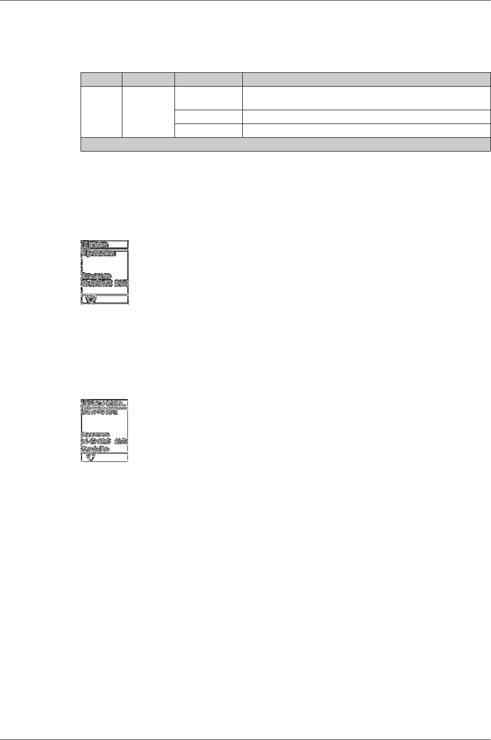
Using Micrologic X Control Units
50 DOCA0102EN-00 05/2016
Alarms & History Menu
Description
The Alarms & History menu contains the following sub-menus:
NOTE: Trip history and alarm history events are listed in chronological order, with the most recent event
first.
Alarm Screen
An alarm screen contains the following information:
A down arrow at the bottom of the screen indicates that another alarm screen can be displayed.
Trips History and Alarms History Screens
A trips history or alarms history screen contains the following information:
Level 1 Level 2 Level 3 Function description
Home Alarms &
History
Alarms 31Contains active alarms of medium and high-level severity. Trips are not
included.
Trips history Contains trip history.
Alarms history Contains alarm history, not including trip history.
1 The figure indicates the number of active alarms
Screen title: Alarm
Alarm description: up to 3 lines of text describing the nature of the alarm
Occurrence
The date and time that the alarm occurred
Screen title: Trip history or Alarms history
Alarm description: up to 3 lines of text describing the nature of the alarm
Occurrence
The date and time of the occurrence of the alarm
Completion
The date and time of the completion of the alarm
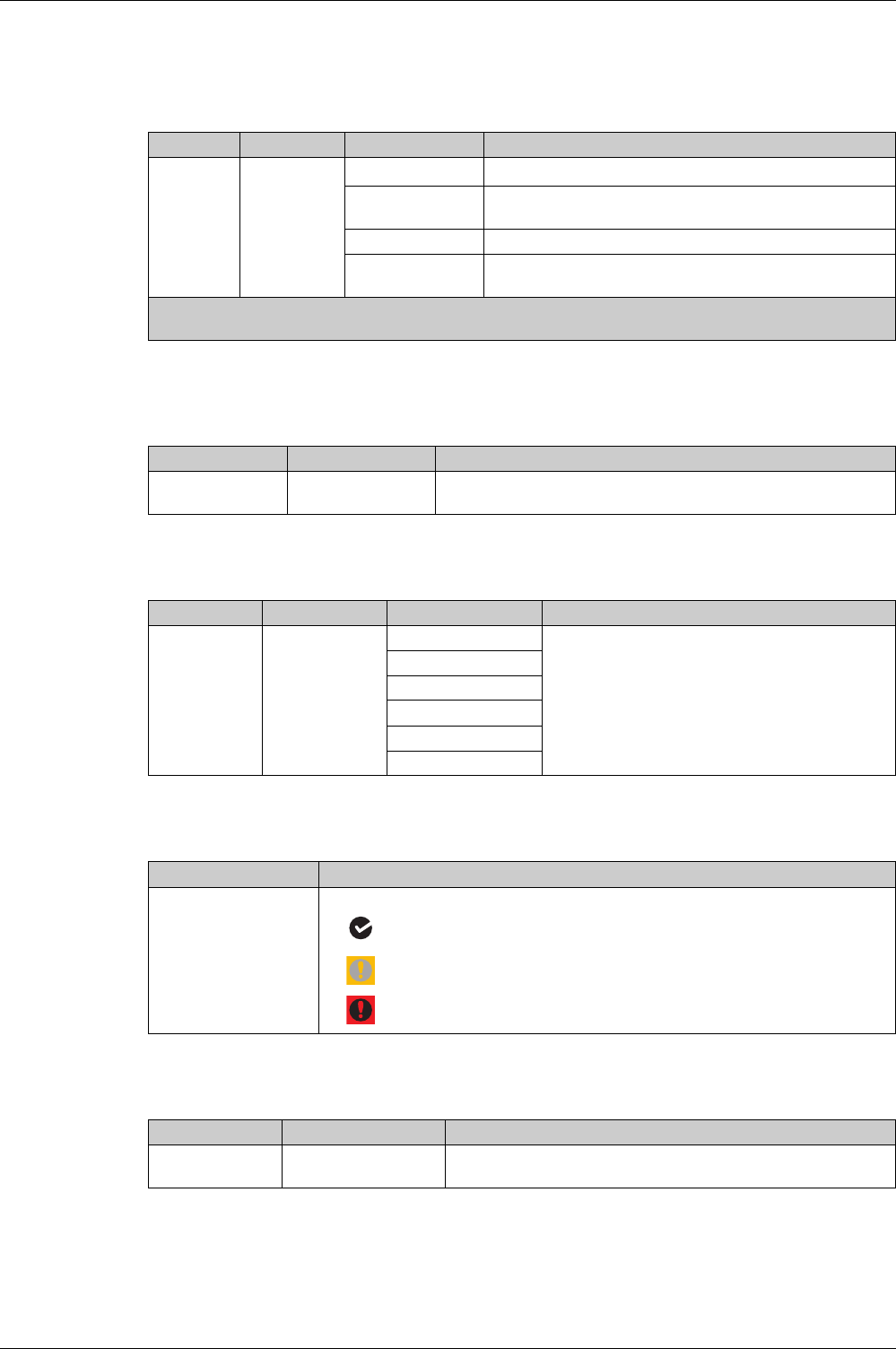
Using Micrologic X Control Units
DOCA0102EN-00 05/2016 51
Maintenance Menu
Description
The Maintenance menu contains the following sub-menus:
Switch to Other Set
The Switch to other set menu is displayed only when Dual Settings is enabled and presents the following
data:
Assistance
The Assistance menu presents the following data:
Health
The Health menu presents the following data:
CB Overview
The CB overview menu presents the following data:
Level 1 Level 2 Level 3 Function description
Home Maintenance Switch to other set1Dual setting configuration
Assistance Contains information describing the maintenance providers,
schedule, equipment and type of the circuit breaker.
Health Describes the monitored health of the circuit breaker.
CB overview Presents information about the circuit breaker and its internal
and external accessories.
1 Displayed only when Dual Settings is enabled and configured mode for switching between set A and set B is Local
HMI
Level 3 Level 4 Parameter name
Switch to other set Switch to set B Selection of the setting group A or B, when the dual settings function is
enabled.
Level 3 Level 4 Level 5 Parameter name
Assistance Firmware Version μLogic version Micrologic X firmware version
ASIC version
TCI version
M&P version
Measure version
CRC32
Level 3 Parameter name
Health Health is represented by one of three icons:
no alarm detected
Orange icon: medium-level alarm detected
Red icon: high-level alarm detected
Level 3 Level 4 Parameter name
CB overview CB block Circuit breaker, frame size, power system, performance level and
version.
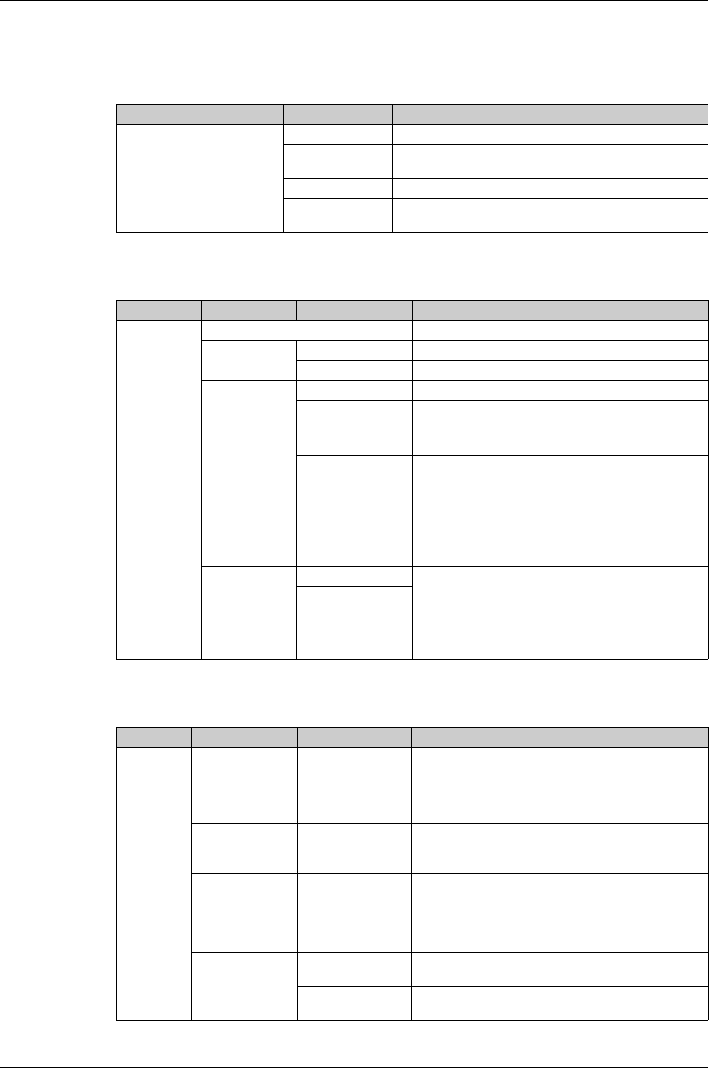
Using Micrologic X Control Units
52 DOCA0102EN-00 05/2016
Configuration Menu
Description
The Configuration menu contains the following sub-menus:
General
The General menu presents the following data:
Network
The Network menu presents the following data:
Level 1 Level 2 Level 3 Function description
Home Configuration General Settings of the HMI display and access to protection settings.
Network Settings of nominal voltage and frequency, power, or power
sign and VT ratio
(see page 52)
.
Measures Settings of measurement calculation
(see page 53)
.
Communication Settings enabling wireless access and the control mode
(see page 53)
.
Level 3 Level 4 Level 5 Parameter name
General Language
(see page 33)
List of display screen languages.
Date & Time
(see page 22)
dd/mm/yyyy Today’s date.
hh:mm:ss Local time.
Quick View
(see page 36)
Scrolling Enable/disable Quick View scrolling.
Auto start (min) The time delay before Quick View scrolling resumes after
an interruption if no button is pressed.
NOTE: Only available when Quick View is enabled.
Pageflow (sec) The length of time for which each Quick View screen is
displayed.
NOTE: Only available when Quick View is enabled.
Timeout (min) The time delay before the current bar graph is displayed if
no button is pressed.
NOTE: Only available when Quick View is not enabled.
Lock protection
(see page 63)
Keypad Enable locking of access to the Protection menu either
through the local HMI keypad or through external access,
to help prevent unauthorized users from editing protection
settings.
Not Allowed: to lock the Protection menu
Allowed: to unlock the Protection menu
External access
Level 3 Level 4 Level 5 Parameter name
Network Nominal Voltage Un (V) Rated voltage.
Setting values include: 208 / 220 / 230 / 240 / 380 / 400 /
415 / 440 / 480 / 500 / 525 / 550 / 575 / 600 / 660 / 690 /
1000 V.
Factory setting = 400.
Nominal
Frequency
Hz Rated frequency
50 Hz (factory setting)
60 Hz
Power Sign
(see page 119)
Power flow sign setting:
P+ = the active power flows from upstream (top) to
downstream (bottom) (factory setting).
P– = the active power flows from downstream (bottom)
to upstream (top).
VT Ratio VT in VT primary voltage.
Values from 100 to 1,250, in increments of 1.
VT out VT secondary voltage.
Values from 100 to 690, in increments of 1.
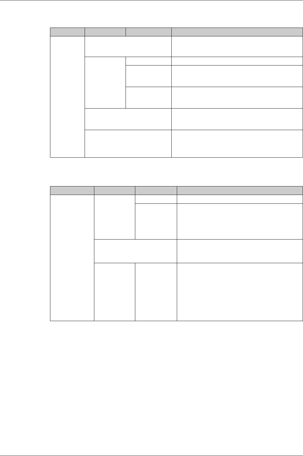
Using Micrologic X Control Units
DOCA0102EN-00 05/2016 53
Measures
The Measures menu presents the following data:
Communication
The Communication menu presents the following data:
Level 3 Level 4 Level 5 Parameter name
Measures PF/VAR Conv
(see page 128)
Sign convention for cos Φ, PF power factor, and reactive
power:
IEC or IEEE (for display only)
System Type
(see page 114)
Nb of poles 3P or 4P, for display only.
ENVT External neutral voltage tap. Setting values include:
If 4P: NO (for display only)
If 3P: YES or NO
ENCT External neutral current transformer. Setting values include:
If 4P: NO (for display only)
If 3P: YES or NO
Total P Calcul
(see page 117)
Total power calculation method:
Vector
Arithmetic
E Calcul
(see page 121)
Energy Accumulation mode. Energy values to be used in
energy calculations:
Absolute
Signed
Level 3 Level 4 Level 5 Parameter name
Communication Bluetooth – Enables Bluetooth control: ON or OFF
BLE timer Time delay before Bluetooth is automatically deactivated:
if no connection is established
if no activity is detected
From 5 to 60 minutes.
Factory setting = 15 minutes
IEEE 802.15.4 Enables IEEE 802.15.4 communication: ON or OFF
NOTE: Enabled only if IEEE 802.15.4 has already been
commissioned through Ecoreach software.
Control mode Mode Selection of source for open/close function
MANU: manually using local mechanical button.
Displays (Push button command only). The control
unit will reject remote open/close orders.
AUTO: In addition to manual orders, the control unit
will accept certain open/close orders, depending on
the configuration of the remote/local parameter. The
configuration is displayed as (Remote control) or
(Local control)
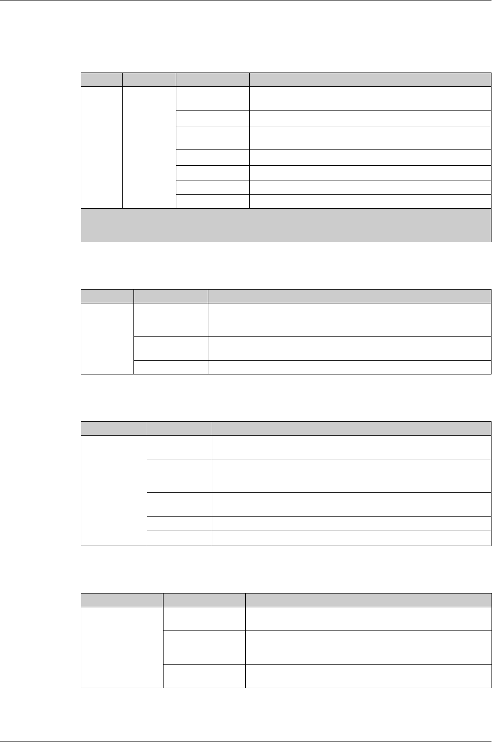
Using Micrologic X Control Units
54 DOCA0102EN-00 05/2016
Protection Menu
Description
The Protection menu contains the following sub-menus:
I Long Time
The I Long time menu presents the following data and settings:
I Short Time
The I Short time menu for Micrologic 5.0 X, 6.0 X, 7.0 X presents the following data and settings:
I Instantaneous
The I Instantaneous menu for Micrologic 2.0 X presents the following data and settings:
Level 1 Level 2 Level 3 Function description
Home Protection I Long time Long-time overcurrent protection
(see page 65)
, L or ANSI code
49RMS
I Short time1Short-time overcurrent protection
(see page 68)
, S or ANSI code 51
I Instantaneous Instantaneous overcurrent protection
(see page 70)
, I or ANSI code
50
I Ground Fault2Ground-fault protection
(see page 72)
, G or ANSI code 50G/51G
Earth Leakage3Earth-leakage protection
(see page 74)
, ANSI code 50G/51G
I Neutral Neutral protection
(see page 76)
Dual Settings Dual settings
(see page 78)
1 Applies to Micrologic 5.0 X, 6.0 X, 7.0 X
2 Applies to Micrologic 6.0 X
3 Applies to Micrologic 7.0 X
Level 3 Level 4 Parameter name
I Long time Ir (x In) Ir long-time overcurrent protection threshold expressed according to the control
unit rated current In.
Used for quick settings: 0.4, 0.5, 0.6, 0.7, 0.8, 0.9, 0.95, 0.98, 1 x In.
Ir (A) Ir long-time overcurrent protection threshold expressed in Amps.
Used for settings with 1 A resolution.
tr @6Ir (s) tr long-time overcurrent protection time delay.
Level 3 Level 4 Parameter name
I Short time Ir (A) Ir long-time overcurrent protection threshold expressed according to the control
unit rated current In, for display only
Isd (x Ir) Isd short-time overcurrent protection threshold expressed according to the Ir
long-time overcurrent protection threshold.
Step = 0.5 x Ir; Rang = 0.5–10 x Ir
Isd (A) Isd short-time overcurrent protection threshold expressed in Amps, for display
only.
tsd (s) tsd short-time overcurrent protection time delay.
I2t (tsd) Enable inverse time curve function: ON or OFF
Level 3 Level 4 Parameter name
I Instantaneous Ir (A) Ir long-time overcurrent protection threshold expressed in Amps, for
display only
Isd (x Ir) Isd short-time overcurrent protection threshold expressed according
to the Ir long-time overcurrent protection threshold.
Step = 0.5 x Ir. Range = .5–10 x Ir
Isd (A) Isd short-time overcurrent protection threshold expressed in Amps, for
display only.
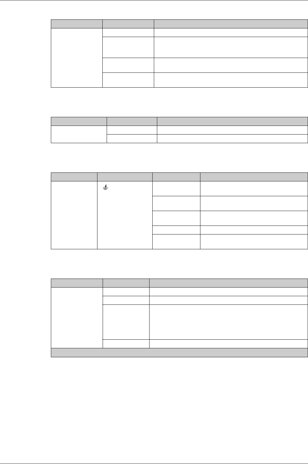
Using Micrologic X Control Units
DOCA0102EN-00 05/2016 55
The I Instantaneous menu for Micrologic 5.0 X, 6.0 X, and 7.0 X presents the following data and settings:
Earth Leakage
The Earth Leakage menu for Micrologic 7.0 X presents the following data and settings:
I Ground Fault
The I Ground Fault menu presents the following data and settings:
I Neutral
The I Neutral menu presents the following data and settings:
Level 3 Level 4 Parameter name
I Instantaneous Protection Enable instantaneous overcurrent protection mode: ON or OFF
Ii (x In) Ii instantaneous overcurrent protection threshold expressed
according to the control unit rated current In.
Step = 0.5 x In. Range = .2–15 x In
Ii (A) Ii instantaneous overcurrent protection threshold expressed in Amps,
for display only.
Ii mode Instantaneous overcurrent protection time delay mode: Standard or
Fast
Level 3 Level 4 Parameter name
Earth Leakage IΔn (A) Earth fault protection threshold expressed in Amps
tΔn (s) Earth fault protection time delay
Level 3 Level 4 Level 5 Parameter name
I Ground Fault I Protection Enable Ground Fault protection mode: ON or
OFF
Ig (x In) Ground fault protection threshold expressed
according to the control unit rated current In
Ig (A) Ground fault protection threshold expressed in
Amps
tg (s) Ground fault protection time delay
I2t (tg) Enable ground fault protection curve function:
ON or OFF
Level 3 Level 4 Parameter name
I Neutral1Nb of poles Number of poles 3P or 4P, for display only
Ir (A) Long time overcurrent protection threshold, for display only.
Protection Set neutral protection:
OFF
0.5
1
Oversized Neutral
IN (A) RMS current on neutral, for display only
1 Applies to 4-pole circuit breakers and 3-pole circuit breakers with ENCT option
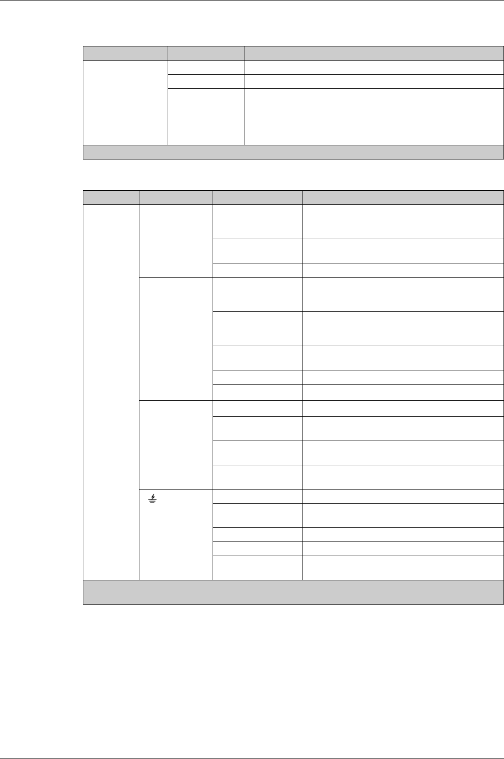
Using Micrologic X Control Units
56 DOCA0102EN-00 05/2016
Dual Settings
The Dual Settings menu presents the following data and settings:
If the Dual Settings menu is enabled the following data and settings are shown and can be configured:
Level 3 Level 4 Parameter name
Dual Settings Dual Settings Enables dual settings: YES or NO
Settings Displays the active configuration A or B, if Dual Settings is enabled.
Switch mode1Displays the configured mode for switching between setting group A and
setting group B:
Local HMI
IO module
Remote ctrl
1 Displayed if Dual Settings is enabled. Configurable through Ecoreach software
Level 4 Level 5 Level 6 Parameter name
Dual settings:
Settings B
I Long time1Ir (x In) Ir long-time overcurrent protection threshold expressed
according to the control unit rated current In, for display
only.
Ir (A) Ir long-time overcurrent protection threshold expressed
in Amps.
tr @6Ir (s) tr long-time overcurrent protection time delay.
I Short time1Ir (A) Ir long-time overcurrent protection threshold expressed
according to the control unit rated current In, for display
only.
Isd (x Ir) Isd short-time overcurrent protection threshold
expressed according to the Ir long-time overcurrent
protection threshold.
Isd (A) Isd short-time overcurrent protection threshold
expressed in Amps, for display only.
tsd (s) tsd short-time overcurrent protection time delay.
I2t Enable inverse time curve function: ON or OFF
I Instantaneous1Protection2Enable instantaneous protection: ON or OFF
Ii (x In)2Ii instantaneous overcurrent protection threshold
expressed according to the control unit rated current In.
Ii (A)2Ii instantaneous overcurrent protection threshold
expressed in Amps, for display only.
Ii mode2Instantaneous overcurrent protection time delay mode:
Standard or Fast
I 1Protection Enable I Ground Fault protection mode: ON or OFF
Ig (x In) Ground fault protection threshold expressed according
to the control unit rated current In
Ig (A) Ground fault protection threshold expressed in Amps
tg (s) Ground fault protection time delay
I2t (tg) Enable ground fault protection curve function: ON or
OFF
1 If Dual Settings is enabled, B is displayed on the upper left side of these screens.
2 Applies to Micrologic 5.0 X, 6.0 X, 7.0 X
Using Micrologic X Control Units
DOCA0102EN-00 05/2016 57
Pop-up Event Messages
Event Message Types and Priority
When the Micrologic X control unit detects any of the following events, a pop-up message is displayed, in
this order of priority:
Bluetooth pairing
Trip
High-level alarm
Medium-level alarm
An event message overrides another event message with lower priority.
An event message overrides both Quick View scrolling and tree navigation operating mode displays.
Bluetooth Pairing Display
The Bluetooth pairing message is displayed during the Bluetooth pairing procedure
(see page 157)
.
The Bluetooth pairing message has the highest priority and overrides all other messages.
The Bluetooth pairing screen is closed when:
The pairing is confirmed on the mobile device
The Bluetooth button on the local HMI is pressed
The Bluetooth pairing timeout expires
If an event message was displayed before or occurs during the Bluetooth pairing, it is displayed after the
Bluetooth pairing message closes. Otherwise the Home screen is displayed.
Pop-up Trip and Alarm Message Displays
Handling Pop-up Trip and Alarm Messages
A trip or alarm message indicates that a potentially serious operating event has occurred. To address the
event, take the following steps:
Message type Description Example
Trip When a trip occurs, the trip message is displayed with a red
backlight.
High-level alarm When a high-level alarm occurs, the high-level alarm message
is displayed with a red backlight.
Medium-level alarm When a medium-level alarm occurs, the medium-level alarm
message is displayed with an orange backlight.
Step Action
1 When the trip or alarm event message displays, press OK.
The display screen displays a message explaining the context of the trip or details of the alarm event. The
backlight color turns white.
2 After reading the explanatory message, take the remedial steps necessary to resolve the underlying
condition that caused the trip or alarm.

Using Micrologic X Control Units
58 DOCA0102EN-00 05/2016
NOTE: The display screen displays the trip or alarm message again, with the appropriate backlight color,
when the message is not acknowledged by pressing OK before the event timeout expires.
For information about handling trip and alarm events, refer to the
Masterpact MTZ2/MTZ3 Circuit Breakers
and Switch-Disconnectors - User Guide
.
For information about how Micrologic X control units handle events, refer to Event Management
(see page 164)
.
Event Timeout
The event timeout can be configured in Configuration → General → Quick View.
If Quick View scrolling is on, the event timeout is the same as the Auto start for Quick View.
If Quick View scrolling is off, the event timeout is displayed as Time out.
For more information about event timeout configuration, refer to Configuring Quick View Scrolling
(see page 36)
.
3 After resolving the cause of the event, press OK to acknowledge the message. The explanatory message
closes, and the display screen shows the Alarm/History menu screen.
NOTE: Return to the Home screen by pressing ESC or the Home button while a pop-up screen or
trip/alarm context screen is displayed.
Step Action

DOCA0102EN-00 05/2016 59
Micrologic X
Protection Functions
DOCA0 102EN-00 05/2016
Protection Fu nctions
Chapter 3
Protection Functions
What Is in This Chapter?
This chapter contains the following sections:
Section Topic Page
3.1 Introduction 60
3.2 Standard Protection Functions 64
3.3 Setting Guidelines 84

Protection Functions
60 DOCA0102EN-00 05/2016
Introduction
Section 3.1
Introduction
Electrical Distribution Protection
Presentation
Micrologic X control units are designed to provide protection against overcurrents and ground-fault
currents.
Micrologic X control units offer protection characteristics that comply with the requirements of standard
IEC 60947-2.
Description
When choosing protection characteristics, take into account:
Overcurrents (overloads and short-circuits) and potential ground-fault currents
Conductors that need protection
Coordination and selectivity between the devices
The presence of harmonic currents
Protection characteristics can be represented on a trip curve that shows the circuit breaker trip time as a
function of the measured current and protection settings. Protection settings are indexed on the rated
current In of the Micrologic X control unit.
Rated Current In
The protection setting ranges depend on the rated current In, defined by the sensor plug inserted in the
Micrologic X control unit.
The sensor plug can be replaced or modified. Mechanical mismatch protection prevents the installation of
a sensor plug that is not compatible with the circuit breaker frame.
For each circuit breaker frame size, the range of sensor plugs available is shown in the following table.
Sensor plug MTZ1 frame rated current MTZ2 frame rated current MTZ3 frame
rated current
In 06 08 10 12 16 08 10 12 16 20 25 32 40 40 50 63
400 A XXX––XX–––––––––
630 A XXXX–XXX––––––––
800 A – XXXXXXXX–––––––
1000 A – – XXX–XXXX––––––
1250 A – – – XX––XXXX–––––
1600 A – – – – X–––XXXX––––
2000 A – – – – – – – – – XXXXX––
2500 A – – – – – – – – – – XXXXX–
3200 A – – – – – – – – – – – XXXXX
4000 A – – – – – – – – – – – – XXXX
5000 A – – – – – – – – – – – – – – XX
6300 A – – – – – – – – – – – – – – – X
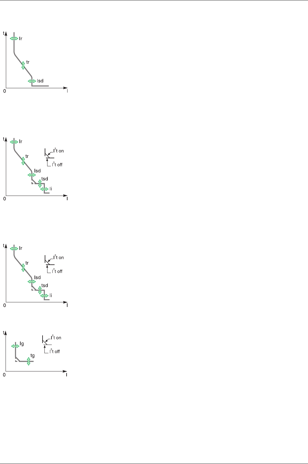
Protection Functions
DOCA0102EN-00 05/2016 61
Micrologic 2.0 X Control Unit
Micrologic 5.0 X Control Unit
Micrologic 6.0 X Control Unit
Micrologic 2.0 X control units provide:
Long-time overcurrent protection (Ir)
Instantaneous overcurrent protection (Isd)
The protection functions of Micrologic 2.0 X control units operate without an auxiliary power supply.
The control unit is powered by the current flowing through the circuit breaker.
Micrologic 5.0 X control units provide:
Long-time overcurrent protection (Ir)
Short-time overcurrent protection (Isd)
Instantaneous overcurrent protection (Ii)
The protection functions of Micrologic 5.0 X control units operate without an auxiliary power supply. The
control unit is powered by the current flowing through the circuit breaker.
Micrologic 6.0 X control units provide:
Long-time overcurrent protection (Ir)
Short-time overcurrent protection (Isd)
Instantaneous overcurrent protection (Ii)
Ground-fault protection (Ig)
The protection functions of Micrologic 6.0 X control units operate without an auxiliary power supply. The
control unit is powered by the current flowing through the circuit breaker.
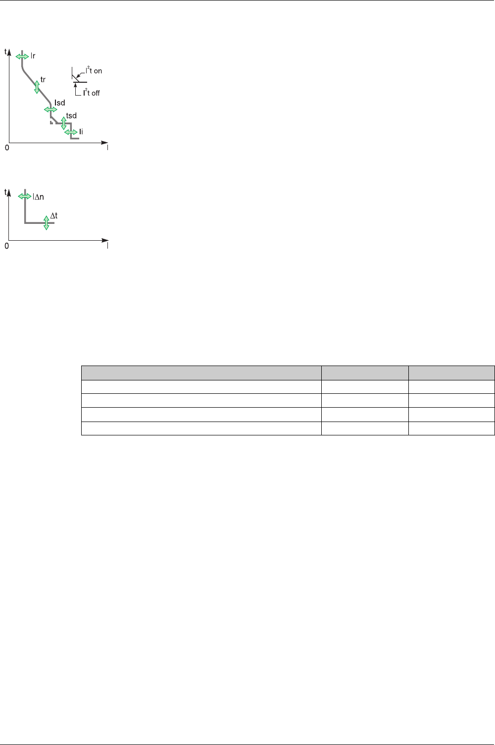
Protection Functions
62 DOCA0102EN-00 05/2016
Micrologic 7.0 X Control Unit
DIN / DINF and SELLIM Instantaneous Protections
DIN / DINF and SELLIM instantaneous protections are internal protections used when the short-circuit
current reaches the withstand limit of the circuit breaker. These protections are not adjustable and are
unlikely to be triggered in normal operating conditions.
The following events can be generated by the DIN / DINF and SELLIM instantaneous protections. Refer to
the event tables
(see page 173)
for more information.
Setting the Protection
Protection functions can be set as follows:
On the Micrologic X display screen, at Home → Protection
With Ecoreach software (password protected)
With Masterpact MTZ mobile App (password protected)
By sending a setting command using the communication network (password protected)
Setting Change Traceability
Changing the protection settings generates one of two events, depending on where the settings are
changed from. The events are logged in the Protection history
(see page 173)
:
Protection setting changed (display screen).
Protection setting changed (Bluetooth, USB or IFE).
Setting changes recorded in the Protection history include the following:
Date and time of the setting change
Previous settings
Unlocking protection settings (refer to following paragraph)
When the circuit breaker is open and the Micrologic X control unit is not connected to a power supply, long-
time, short-time, instantaneous and ground-fault protection settings and the date of the last change can be
accessed through NFC communication.
Micrologic 7.0 X control units provide:
Long-time overcurrent protection (Ir)
Short-time overcurrent protection (Isd)
Instantaneous overcurrent protection (Ii)
Earth-leakage protection (IΔn)
The protection functions of Micrologic 7.0 X control units operate without an auxiliary power supply.
The long-time, short-time and instantaneous overcurrent protections are powered by the current
flowing through the circuit breaker.
The earth-leakage protection is powered by the system voltage via the VPS voltage power supply
module.
Events History Severity
Ultimate self-protection trip (SELLIM) Trip High
Ultimate self-protection trip (DIN / DINF) Trip High
Ultimate self-protection trip (SELLIM) operate Protection Medium
Ultimate self-protection trip (DIN / DINF) operate Protection Medium

Protection Functions
DOCA0102EN-00 05/2016 63
Locking the Protection Settings
Locking the protection settings is only possible from the Micrologic X display screen at Home →
Configuration → General → Lock protection. It enables you to lock access to protection settings:
From the Micrologic X display screen
From an external access
Select Not Allowed to lock access. Access is allowed by default.
Changing the access to protection settings generates two events, which are logged in the Protection
history
(see page 173)
:
Protection settings on local screen is unlocked
Remote lock for protection settings is unlocked

Protection Functions
64 DOCA0102EN-00 05/2016
Standard Protection Fun ctions
Section 3.2
Standard Protection Functions
What Is in This Section?
This section contains the following topics:
Topic Page
Long-Time Overcurrent Protection (L or ANSI Code 49RMS) 65
Short-Time Overcurrent Protection (S or ANSI Code 51) 68
Instantaneous Overcurrent Protection (I or ANSI Code 50) 70
Ground-Fault Protection (G or ANSI Code 50G/51G) 72
Earth-Leakage Protection (ANSI Code 50G/51G) 74
Neutral Protection 76
Dual Settings 78
Zone Selective Interlocking (ZSI) 80
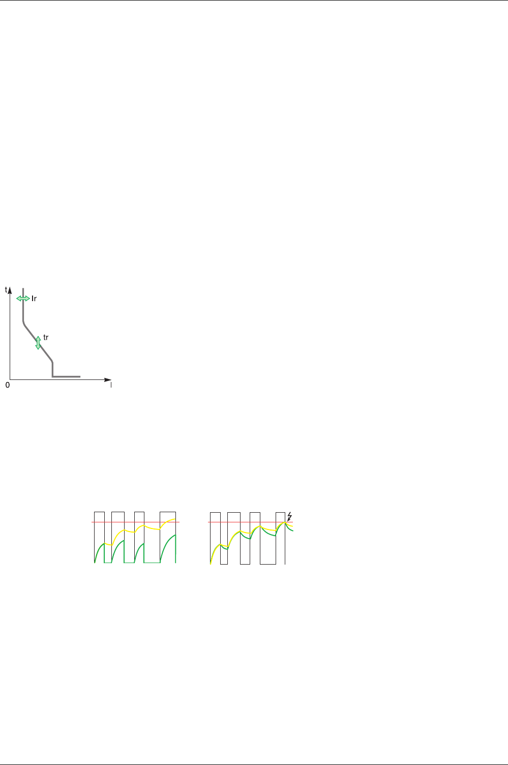
Protection Functions
DOCA0102EN-00 05/2016 65
Long-Time Overcurrent Protection (L or ANSI Code 49RMS)
Presentation
Long-time overcurrent protection protects cables, busbars, and busbar trunking against overloads, based
on the true RMS current. It is implemented independently for each phase and for the neutral.
This protection function is an overcurrent time-dependent protection with thermal memory. It operates as
a thermal image, using the heating and cooling model of a conductor. After tripping, the protection
continues to integrate the cooling of the conductor.
This protection function can be used also for transformer or generator protection thanks to the wide range
of settings offered.
Availability
Long-time overcurrent protection is available on:
Micrologic 2.0 X, 5.0 X, 6.0 X, and 7.0 X control units
3-pole and 4-pole circuit breakers
Long-time overcurrent protection is powered by the current flowing through the internal current
transformers of the circuit breaker and it does not require additional external power supply.
Operating Principle
Thermal Image
The control unit uses the calculation of a thermal image to evaluate the conductor heat rise and precisely
monitor the thermal state of the conductors.
Example:
Comparison of the heat rise calculation without thermal image (diagram A) and with thermal image
(diagram B):
0 Instantaneous current (cyclical) in the load
1 Conductor temperature
2 Thermal state calculated without thermal image (diagram A), with thermal image (diagram B)
3 Long-time overcurrent protection threshold
Control unit without thermal image: On each current pulse, the control unit only considers the thermal
effect on the pulse under consideration. No tripping occurs despite the build-up in conductor heat rise.
Control unit with thermal image: The control unit adds the thermal effect of successive current pulses.
Tripping occurs based on the actual thermal state of the conductor.
The thermal image function protects cables and busbars from overheating in case of low-amplitude
repetitive faults. Such faults can be due to repetitive motor starts, fluctuating load, intermittent ground
faults, or subsequent closing after a fault.
Long-time overcurrent protection is based on the true RMS current of phases and neutral, up to
harmonic 15.
Long-time overcurrent protection is implemented independently for each phase and for neutral when
present
(see page 76)
.
1
3
2
1
2
3
AB00

Protection Functions
66 DOCA0102EN-00 05/2016
Traditional electronic protection does not protect against repetitive faults because the duration of each
overload detected above the threshold setting is too short to trigger effective tripping. However, each
overload involves a temperature rise in the installation. When cumulated, overloads can overheat the
system.
Thanks to its thermal memory, the thermal image function remembers and integrates thermal heating
caused by each overload detected above the threshold setting:
Before tripping, the integrated heating value reduces the associated time delay. The reaction of the
control unit is closer to the real heating of the power network system.
After tripping, the thermal function reduces the time delay when closing the circuit breaker on an
overload.
The thermal memory works whatever the current value. It offers an accurate image of the cable or busbar
thermal status. The time constant is the same for heating and cooling.
In the case of a control unit that is not supplied, the thermal memory is performed by a capacitor, which
implies a fixed cooling time constant. The time constant is equivalent to a tr setting of 12 seconds.
Thermal Memory Reset
The thermal memory can be reset with Ecoreach software.
The thermal memory reset is recorded as an event.
Setting the Protection
The long-time overcurrent protection settings are:
Ir long-time overcurrent protection threshold
tr long-time overcurrent protection time delay
They can be set as follows:
On the Micrologic X display screen, at Home → Protection → I Long time
With Ecoreach software
With Masterpact MTZ mobile App
By sending a setting command using the communication network.
Long-time overcurrent protection can be duplicated when dual settings are activated
(see page 78)
.
Protection Settings
The tr long-time overcurrent protection time delay is given in cold-state conditions, and for a phase or
neutral current equal to 6 x Ir.
When the current is higher than Isd or Ii, only short-time overcurrent protection and instantaneous
protection are operational.
Tripping Time According to tr Time Delay
Protection Characteristics
The accuracy on the tr time delay is:
-20% to 0% when tr > 2 s
-25% to 0% when tr = 2 s
-30% to 0% when tr < 2 s
Ir characteristics:
I < 1.05 x Ir: no trip
I > 1.2 x Ir: trip
Setting Unit Range Step Factory setting
Ir threshold A 0.4–1 x In 1 A 1 x In
tr time delay s 0.5–24 0.5 0.5
tr setting (tripping time at 6 x Ir) 0.5 s 1s 2s 4s 8s 12 s 16 s 20 s 24 s
Resulting tripping time at 1.5 x Ir 12.5 s 25 s 50 s 100 s 200 s 300 s 400 s 500 s 600 s
Resulting tripping time at 7.2 x Ir 0.34 s 0.69 s 1.38 s 2.7 s 5.5 s 8.3 s 11 s 13.8 s 16.6 s

Protection Functions
DOCA0102EN-00 05/2016 67
Predefined Events
The function generates the following predefined events:
Predefined events cannot be modified by the user. For general information on events, refer to Event
management.
(see page 164)
Event History Severity
Ir trip Trip High
Ir operate Protection Medium
Ir prealarm (I>90%Ir) Protection Low
Ir start (I>105%Ir) Protection Medium
Thermal memory reset order Protection Low
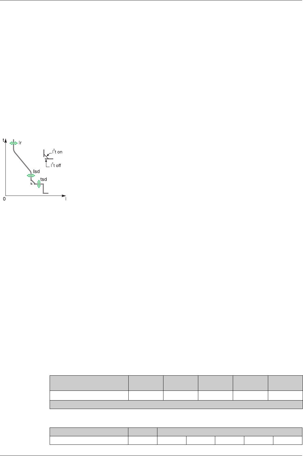
Protection Functions
68 DOCA0102EN-00 05/2016
Short-Time Overcurrent Protection (S or ANSI Code 51)
Presentation
Short-time overcurrent protection protects equipment against phase-to-phase, phase-to-neutral and
phase-to-ground short circuits with total selectivity. It includes two characteristics, definite time and inverse
time, which depend on the status of the I²t setting.
Availability
Short-time overcurrent protection is available on:
Micrologic 5.0 X, 6.0 X, and 7.0 X control units
3-pole and 4-pole circuit breakers
Short-time overcurrent protection is powered by the current flowing through the internal current
transformers of the circuit breaker and it does not require an additional external power supply.
Operating Principle
Short-time overcurrent protection is based on the true RMS current of phases and neutral, up to harmonic
15.
In order to trip on an intermittent fault, the control unit accumulates the intermittent currents in the short-
time tripping range that do not last long enough to trigger a trip. This accumulation may lead to shorter
tripping times than those set.
Setting the Protection
The short-time overcurrent protection settings are:
Isd short-time overcurrent protection threshold
tsd short-time overcurrent protection time delay
I²t short-time overcurrent protection curve (I²t ON or I²t OFF)
They can be set as follows:
On the Micrologic X display screen, at Home → Protection → I Short time
With Ecoreach software
With Masterpact MTZ mobile App
By sending a setting command using the communication network. This function is password protected.
Short-time overcurrent protection can be duplicated when dual settings are activated
(see page 78)
.
Protection Settings
The following Isd settings are available:
tsd time delay setting is as follows:
The short-time overcurrent threshold Isd sets the level of short-circuit current at which the circuit
breaker trips when reaching the short-time overcurrent time delay.
The short-time overcurrent time delay tsd sets the length of time during which the circuit breaker carries
a short circuit within the short-time overcurrent threshold range.
The short-time overcurrent time delay can be adjusted to:
Four setting values with I2t ON.
Up to 10 Ir, the tripping curve is an inverse time curve. The time delay decreases as the current
increases.
Above 10 Ir, the tripping curve is a definite time curve with a constant tripping time.
Five setting values with I2t OFF. The tripping curve is a definite time curve with a constant tripping
time.
Setting Unit Range Step Factory
setting
Accuracy
Isd threshold A 1.5 to 10 x Ir 0.5 x Ir11.5 x Ir +/- 10%
1 Finer resolution settings are possible with Ecoreach software and Masterpact MTZ mobile App
Setting Unit Setting Value
tsd with I²t OFF s 0 0.1 0.2 0.3 0.4
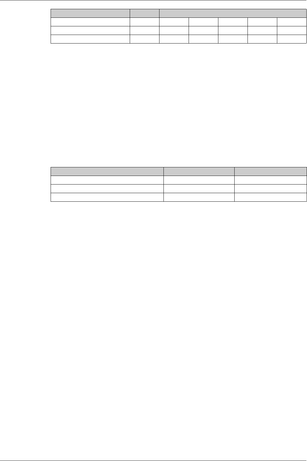
Protection Functions
DOCA0102EN-00 05/2016 69
The tsd time delay factory setting is 0 s with I²t OFF.
Zone Selective Interlocking (ZSI)
The ZSI characteristics and external wiring of the zone selective interlocking function, are described
specifically
(seepage80)
.
If ZSI IN is not set to 1 (open circuit between Z3 and Z4 terminals), the maximum breaking time is 0.08 s
regardless of the tsd setting value.
When ZSI IN is set to 1 and connected to the ZSI OUT of a downstream device (or when the ZSI function
is not used and there is a jumper between the Z3 and Z4 terminals), the tsd time delay is used.
The Isd pick up activates ZSI OUT (Z1 and Z2 terminals).
NOTE: Masterpact MTZ circuit breakers are delivered with a jumper installed between Z3 and Z4.
Predefined Events
The function generates the following predefined events:
Predefined events cannot be modified by the user. For general information on events, refer to Event
Management
(see page 163)
.
tsd with I²t ON s – 0.1 0.2 0.3 0.4
Non-tripping time s > 0.02 > 0.08 > 0.14 > 0.23 > 0.35
Maximum breaking time s < 0.08 < 0.14 < 0.20 < 0.32 < 0.50
Setting Unit Setting Value
Event History Severity
Isd trip Trip High
Isd operate Protection Medium
Isd start (I > Isd) Protection Medium
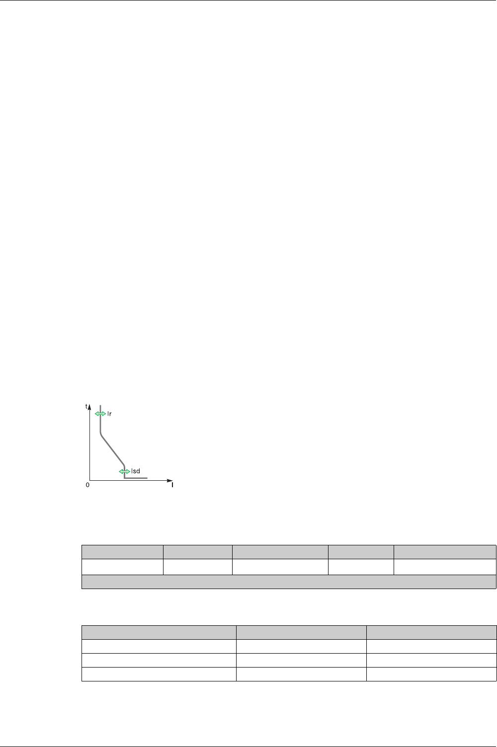
Protection Functions
70 DOCA0102EN-00 05/2016
Instantaneous Overcurrent Protection (I or ANSI Code 50)
Presentation
Instantaneous protection protects equipment against phase-to-phase, phase-to-neutral and phase-to-
ground short circuits. The protection operates with a definite time characteristic. It trips without additional
time delay as soon as the setting current is exceeded.
The protection offers two typical total breaking times:
Standard breaking time of 50 ms, used for applications requiring selectivity. Full selectivity can be
ensured with any Compact NSX circuit breaker installed downstream of a Masterpact device (for
Ue ≤ 440V and MTZ other than type L. Refer to selectivity tables for details).
Fast breaking time of 30 ms, typically used for applications where the thermal constraints of the
equipment need to be limited and when selectivity is not required.
NOTE: On Micrologic 2.0 X, instantaneous protection is a short-time protection without time setting.
Availability
Instantaneous overcurrent protection is available on:
Micrologic 2.0 X, 5.0 X, 6.0 X, and 7.0 X control units
3-pole and 4-pole circuit breakers
It is powered by the current flowing through the internal current transformers of the circuit breaker and it
does not require an additional external power supply.
Operating Principle
The instantaneous overcurrent protection threshold sets the level of short-circuit current at which the circuit
breaker trips with no intentional time delay.
For Micrologic 5.0 X, 6.0 X, 7.0 X control units, instantaneous overcurrent protection can be disabled.
Instantaneous overcurrent protection overrides short-time overcurrent protection when the instantaneous
overcurrent threshold is adjusted to the same or a lower setting than the short-time overcurrent threshold.
Setting the Protection for Micrologic 2.0 X
Protection Settings for Micrologic 2.0 X
Protection Characteristics for Micrologic 2.0 X
The instantaneous overcurrent protection setting for Micrologic 2.0 X is:
Isd short-time overcurrent protection threshold (without time setting)
It can be set as follows:
On the Micrologic X display screen, at Home → Protection → I Instantaneous
With Ecoreach software
With Masterpact MTZ mobile App
By sending a setting command using the communication network. This function is
password-protected.
Instantaneous overcurrent protection can be duplicated when dual settings are
activated
(see page 78)
.
Setting Unit Range Step Factory setting
Isd threshold A 1.5–10 x Ir 0.5 x Ir11.5 x Ir
1 Finer resolution settings are possible with Ecoreach software and Masterpact MTZ mobile App
Characteristic Unit tsd
Breaktime at 2 x threshold ms ≤ 80
Non-tripping time ms > 20
Accuracy on threshold % +/- 10
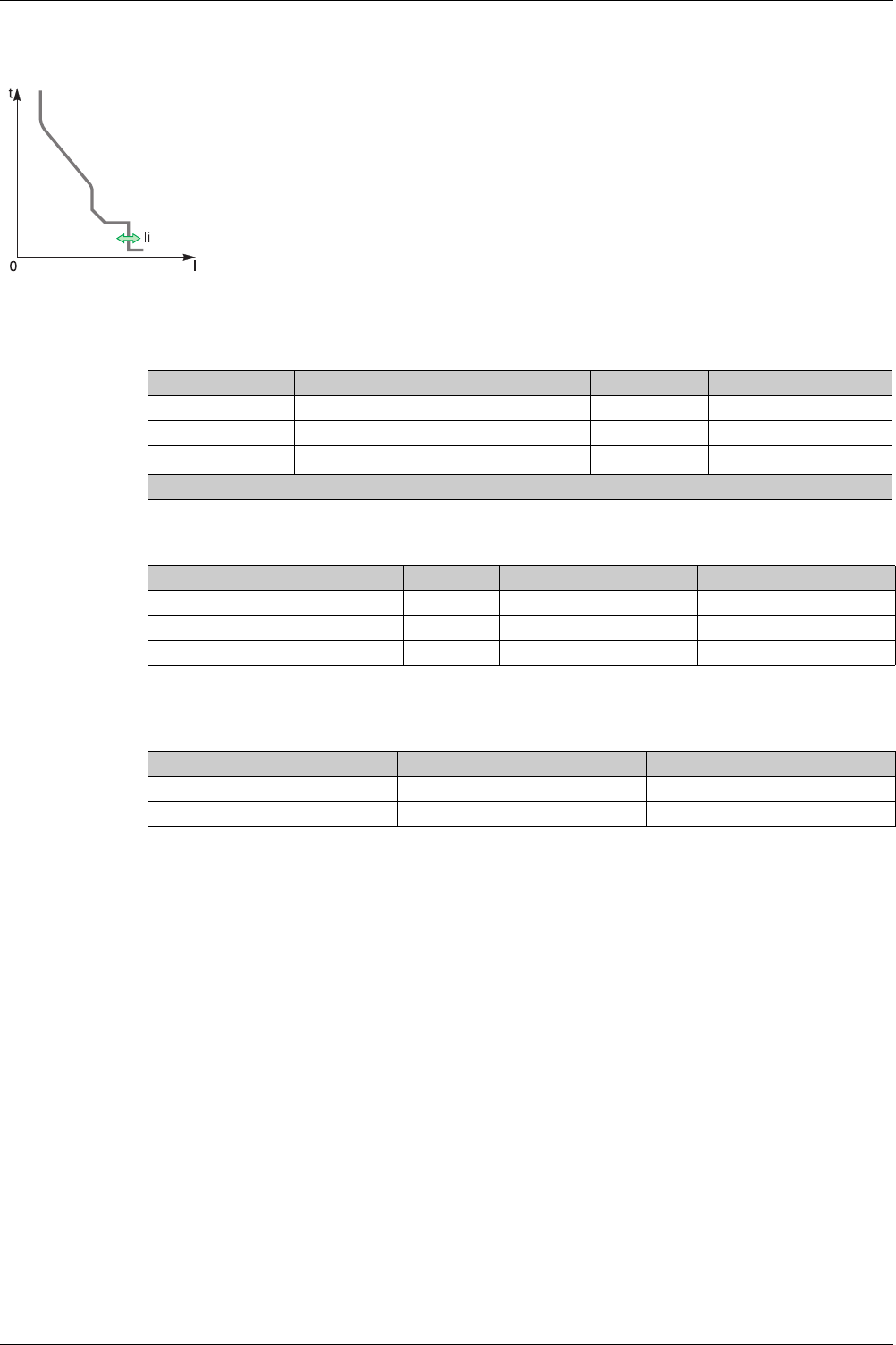
Protection Functions
DOCA0102EN-00 05/2016 71
Setting the Protection for Micrologic 5.0 X, 6.0 X, 7.0 X
Protection Settings for Micrologic 5.0 X, 6.0 X, 7.0 X
Protection Characteristics for Micrologic 5.0 X, 6.0 X, 7.0 X
Predefined Events
The function generates the following predefined events:
Predefined events cannot be modified by the user. For general information on events, refer to Event
Management
(see page 163)
.
The instantaneous overcurrent protection settings are:
Ii enable
li type
Ii instantaneous overcurrent protection threshold
They can be set as follows:
On the Micrologic X display screen, at Home → Protection → I Instantaneous
With Ecoreach software
With Masterpact MTZ mobile App
By sending a setting command using the communication network. This function is password-
protected.
Instantaneous overcurrent protection can be duplicated when dual settings are activated
(see page 78)
.
Setting Unit Range Step Factory setting
Ii enable – ON/OFF – ON
Ii type – Standard / Fast – Standard
Ii threshold A 1.5–15 x In 0.5 x Ir11.5 x In
1 Finer resolution settings are possible with Ecoreach software and Masterpact MTZ mobile App
Characteristic Unit Ii type is set to Standard Ii type is set to Fast
Breaktime at 2 x threshold ms ≤ 50 ≤ 30
Non-tripping time ms > 20 0
Accuracy on threshold % +/- 10 +/- 10
Event History Severity
Ii trip Trip High
Ii operate Protection Medium
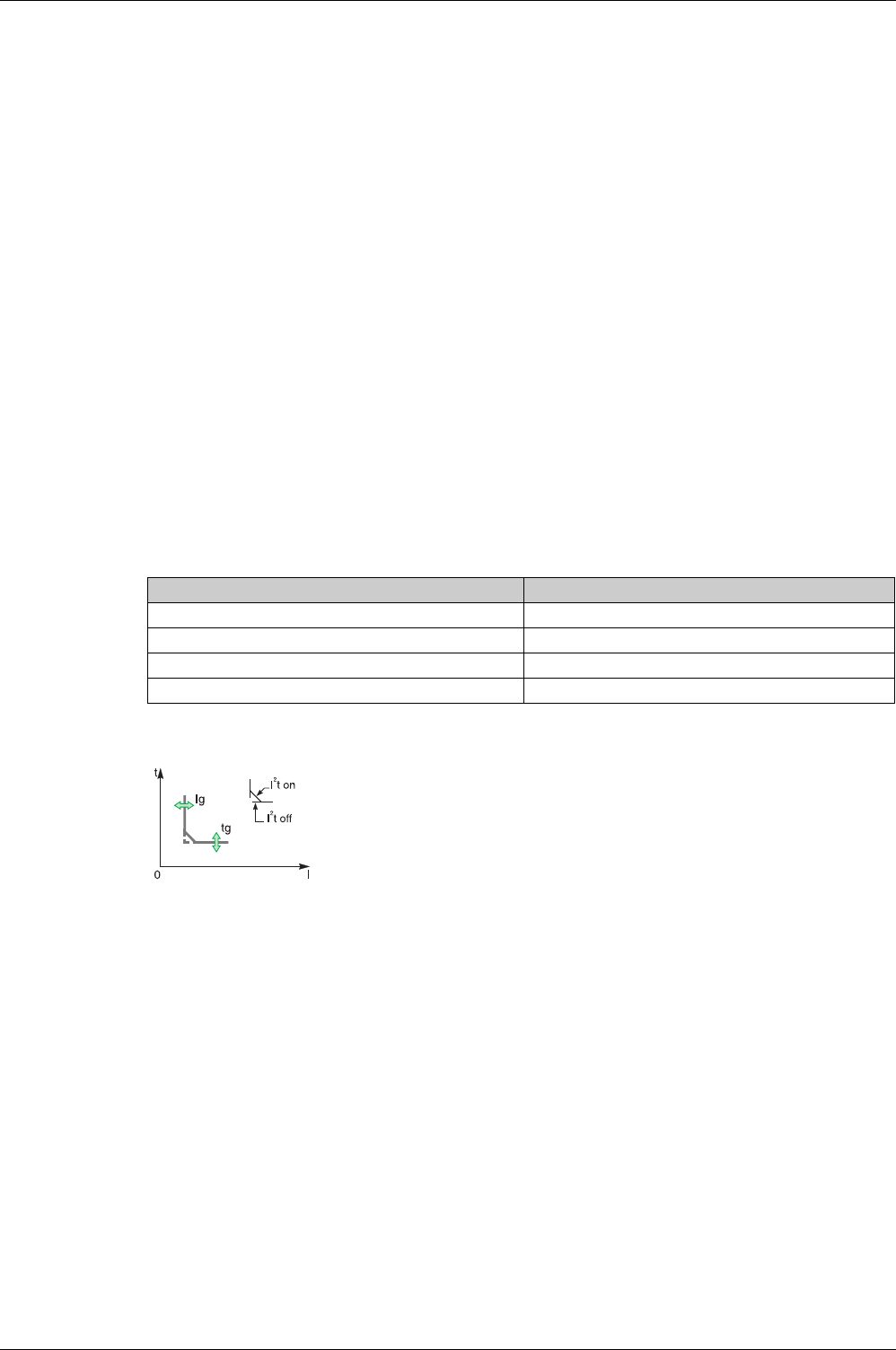
Protection Functions
72 DOCA0102EN-00 05/2016
Ground-Fault Protection (G or ANSI Code 50G/51G)
Presentation
Ground-fault protection ensures protection against phase-to-ground fault, which is more sensitive than
protection based on phase current only. It is generally used in TN-S systems but could also be used in
other earthing systems. Ground-fault protection is based either on the summation of the phases and
neutral current or on the signal delivered by an external sensor, source ground return (SGR) current
transformer through the MDGF module.
NOTE: Ground-fault protection is also called earth-fault protection.
Availability
Ground-fault protection is available on:
Micrologic 6.0 X control units
3-pole and 4-pole circuit breakers
External sensors can be used:
Source ground return protection: including ground-fault protection and an SGR sensor installed around
the connection of the transformer neutral point to ground.
External Neutral Current Transformer (ENCT): measurement of the current on neutral
Ground-fault protection is powered by the current flowing through the internal current transformers of the
circuit breaker and it does not require an additional external power supply.
Operating Principle
The ground-fault current is calculated or measured according to the circuit breaker configuration, as shown
in the following table.
Ground-fault protection is based on the true RMS current of phases and neutral, up to harmonic 15.
In order to trip on an intermittent fault, the control unit accumulates the intermittent currents in the ground-
fault tripping range that do not last long enough to trigger a trip. This accumulation leads to shorter tripping
times than those set.
Setting the Protection
Ground-fault protection can be enabled or disabled.
The ground-fault protection settings are:
Ig enable
Ig ground-fault protection threshold
tg ground-fault protection time delay
Ground-fault protection curve (I²t ON or I²t OFF)
They can be set as follows:
On the Micrologic X display screen, at Home → Protection → I Ground Fault
With Ecoreach software
Circuit breaker configuration Ig ground-fault current
3P Ig = I1 + I2 + I3
4P Ig = I1 + I2 + I3 + IN
3P + ENCT Ig = I1 + I2 + I3 + IN (ENCT)
3P or 4P + SGR Ig = ISGR
The ground-fault protection threshold Ig sets the level of ground-fault current at which
the circuit breaker trips when reaching the ground-fault protection time delay tg.
The time delay tg sets the length of time during which the circuit breaker carries a
ground-fault within the ground-fault protection threshold Ig range.
The time delay tg can be adjusted to:
Four setting values with I²t ON. In this case, the tripping curve is an inverse time
curve up to 2 x Ir, meaning that the time delay decreases as the current increases.
Above 2 x Ir, the tripping curve is a definite time curve with a constant tripping time.
Five setting values with I²t OFF. In this case, the tripping curve is a definite time
curve with a constant tripping time.
Protection Functions
DOCA0102EN-00 05/2016 73
With Masterpact MTZ mobile App
By sending a setting command using the communication network. This function is password-protected.
The ground-fault protection can be duplicated when dual settings are activated
(see page 78)
.
Protection Settings
The default tg time delay setting value is 0 s with I²t OFF.
Testing the Protection
Test the operation of ground-fault protection as follows:
Zone Selective Interlocking (ZSI)
The ZSI characteristics and external wiring of the zone selective interlocking function, are described
specifically
(seepage80)
.
If ZSI IN is not set to 1(open circuit between Z3 and Z4 terminals), the maximum breaking time is 0.08 s
regardless of the tg setting value.
When ZSI IN is set to 1 and connected to the ZSI OUT of a downstream device (or when ZSI is not used,
there is a jumper between the Z3 and Z4 terminals), the tg time delay is used.
The Ig pick up activates ZSI OUT (Z1 and Z2 terminals).
NOTE: Masterpact MTZ circuit breakers are delivered with a jumper installed between Z3 and Z4.
Predefined Events
The function generates the following predefined events:
Predefined events cannot be modified by the user. For general information on events, refer to Event
Management
(see page 163)
.
Setting Unit Range Step Factory setting Accuracy
Ig enable – ON / OFF – ON –
Ig threshold A 0.2–1 x In 0.1 x In10.2 x In +/– 10%
1 Finer resolution settings are possible with Ecoreach software and Masterpact MTZ mobile App
Setting Unit Setting Value
tg with I²t OFF s 0 0.1 0.2 0.3 0.4
tg with I²t ON s – 0.1 0.2 0.3 0.4
Non-tripping time s > 0.02 > 0.08 > 0.14 > 0.23 > 0.36
Maximum breaking time s < 0.08 < 0.14 < 0.20 < 0.32 < 0.50
Step Action
1 Check that the circuit breaker is closed and the control unit is supplied with power (ready LED is
flashing).
2 Press the test button (T) on the front face of the Micrologic X control unit. This action is recorded as an
event.
3 The circuit breaker trips. An event is generated.
4 If the circuit breaker does not trip, an event is generated. Contact your field service representative.
Event History Severity
Ig trip Trip High
I∆n/Ig test trip Trip High
Ig start Protection Low
Ig operate Protection Medium
I∆n/Ig test button pressed Diagnostic Low
I∆n/Ig test trip failed Diagnostic High
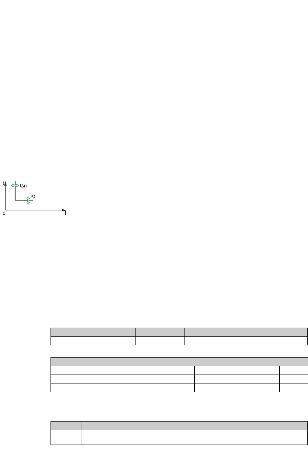
Protection Functions
74 DOCA0102EN-00 05/2016
Earth-Leakage Protection (ANSI Code 50G/51G)
Presentation
Earth-leakage protection is a protection against earth fault with a very high sensitivity. It is generally used
in TT or IT earthing systems but could also be used in TN earthing systems in some circumstances. Earth-
leakage protection is a residual current protection based on current measured by a rectangular sensor
encompassing the three phases or the three phases and neutral. Micrologic 7.0 X earth-leakage protection
with VPS module complies with IEC 60947-2 Annex B. It is a type A residual-current device (RCD).
Availability
Earth-leakage protection is available on:
Micrologic 7.0 X control units connected to an external rectangular sensor
3-pole and 4-pole circuit breakers
The external rectangular sensor is required to measure the residual current.
The VPS voltage power supply module is delivered with Micrologic 7.0 X control units to supply power to
the control unit in case of a low level fault and no load, where the power supply based on current flowing
through the circuit breaker is not high enough.
The VPS is mandatory to comply with IEC 60947-2 Annex B.
Operating Principle
Setting the Protection
The earth-leakage protection settings are:
IΔn earth-leakage protection threshold
tΔn earth-leakage protection time delay
They can be set as follows:
On the Micrologic X display screen, at Home → Protection → I Earth Leakage
With Ecoreach software
With Masterpact MTZ mobile App
By sending a setting command using the communication network.
Protection Settings
Testing the Protection
Test the operation of earth-leakage protection as follows:
Earth-leakage protection is definite time.
The earth-leakage protection threshold IΔn sets the level of earth-leakage at which the circuit breaker
trips when reaching the earth-leakage protection time delay tΔn.
Setting Unit Range Step Factory setting
IΔn threshold A 0.5 – 30 0.1 0.5
Setting Unit Setting Value
tΔn time delay s 0.06 0.15 0.23 0.35 0.80
Non-tripping time s > 0.06 > 0.15 > 0.23 > 0.35 > 0.80
Maximum breaking time s < 0.14 < 0.23 < 0.35 < 0.80 < 1.00
Step Action
1 Check that the circuit breaker is closed and the control unit is supplied with power (ready LED is
flashing).

Protection Functions
DOCA0102EN-00 05/2016 75
Predefined Events
The function generates the following predefined events:
Predefined events cannot be modified by the user. For general information on events, refer to Event
Management
(see page 164)
.
2 Press the test button (T) on the front face of the Micrologic X control unit. This action is recorded as an
event.
3 The circuit breaker trips. An event is generated.
4 If the circuit breaker does not trip, an event is generated. Contact your field service representative.
Step Action
Event History Severity
IΔn trip Trip High
I∆n/Ig est trip Trip High
IΔn start Protection Low
IΔn operate Protection Medium
I∆n/Ig test button pressed Diagnostic Low
I∆n/Ig test trip failed Diagnostic High
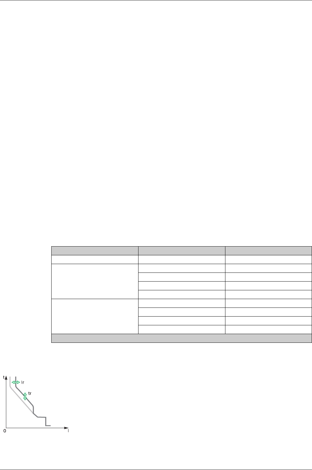
Protection Functions
76 DOCA0102EN-00 05/2016
Neutral Protection
Presentation
A long time overcurrent protection function is dedicated to the neutral protection.
Availability
Neutral protection is available on:
Micrologic 2.0 X, 5.0 X, 6.0 X, and 7.0 X control units
3-pole circuit breakers with the ENCT option (External Neutral Current Transformer) to measure the
neutral current
4-pole circuit breakers
Description
Where the cross-sectional area of the neutral conductor is at least equivalent to that of the phase
conductor, and the current in the neutral is expected not to exceed the value in the phase conductor, it is
not necessary to provide overcurrent protection for the neutral conductor.
The neutral conductor must have protection against short-circuit current if:
The cross-sectional area of the neutral conductor is less than the cross-sectional area of the phase
conductors
Non-linear loads generating third order harmonics (or multiples thereof) are installed
It may be necessary to switch off the neutral for operational reasons (multiple source diagram) or safety
reasons (working with power off).
To summarize, the neutral conductor can be:
Non-distributed (3-pole circuit breaker)
Distributed, not switched off and not protected (3-pole circuit breaker)
Distributed, not switched off but protected (3-pole circuit breaker with ENCT option)
Distributed, switched off and protected (4-pole circuit breaker)
Micrologic X control units are suitable for all protection types. They incorporate the OSN (Oversized
Neutral) function, which manages protection of the neutral conductor when third-order harmonic currents
(and multiples thereof) are present.
Operating Principle
Circuit Breaker Possible Types Neutral Protection
3-pole circuit breaker 3P, 3D Off
3-pole circuit breaker with ENCT
option
3P, 3D Off
3P, 3D + N/2 Half neutral
3P, 3D + N Full neutral
3P, 3D + OSN Oversized neutral
4-pole circuit breaker 4P, 3D Off
4P, 3D + N/2 Half neutral
4P, 4D Full neutral
4P, 4D + OSN Oversized neutral
P: Pole, D: Control unit, N: Neutral protection
Neutral protection has the same characteristics as phase protection:
Its threshold is proportional to the long-time protection threshold Ir.
It has the same tr time delay values as long-time protection.
Its short-time and instantaneous protections are identical.
Protection Functions
DOCA0102EN-00 05/2016 77
Declaring the External Neutral Current Transformer (ENCT) on 3-Pole Circuit Breakers
On 3P circuit breakers the ENCT option must be declared in one of the following ways:
On the Micrologic X display screen, at Home → Configuration → Measures → System Type → ENCT
With Ecoreach software
With Masterpact MTZ mobile App
By sending a setting command using the communication network. This function is password-protected.
Setting the Neutral Protection for 3-Pole and 4-Pole Circuit Breakers
Set the type of neutral protection in one of the following ways:
On the Micrologic X display screen, at Home → Protection → Neutral
With Ecoreach software
With Masterpact MTZ mobile App
By sending a setting command using the communication network. This function is password-protected.
The table below shows the setting values of the neutral long-time protection and threshold for the type of
neutral protection selected:
Neutral protection type Neutral long-time threshold value
OFF No long-time protection for neutral
0.5 Ir/2
1Ir
OSN 3-pole (ENCT) 1.6 x Ir
4-pole 1.6 x Ir limited to In

Protection Functions
78 DOCA0102EN-00 05/2016
Dual Settings
Presentation
Dual settings function consists of two sets of parameters on the following protections, according to the type
of Micrologic X control unit:
Long-time overcurrent protection
Short-time overcurrent protection
Instantaneous overcurrent protection
Ground-fault protection
The user may switch from one set to the other under certain operating conditions. A typical application is
to adjust short-circuit protection when the circuit breaker can be supplied by two sources with very different
short-circuit currents. For example, the circuit breaker is supplied by either the grid or a generator.
Availability
The dual settings function is available on Micrologic 2.0 X, 5.0 X, 6.0 X, 7.0 X.
Operating Principle
When the dual settings function is enabled, two sets of protection parameters are available:
Set A corresponds to the settings currently selected
Set B is a new set of protection parameters, which can be set as described in Setting the Function
(see page 78)
.
Set B is activated as follows:
On the Micrologic X display screen at Home → Maintenance → Switch to other set → Switch to set B.
By sending a setting command using the communication network. For more information refer to the
Masterpact MTZ - Modbus Communication Guide
.
By a digital input provided by IO module. For more information refer to the
IO Input/Output Application
Module for One Circuit Breaker - Instruction Sheet
Without an external command, Ir, tr, Isd, tsd, Ii, Ig, and tg settings are those of Set A.
When the Activate Set B external command is sent, the Ir, tr, Isd, tsd, Ii, Ig, and tg settings switch to those
of Set B.
When the Dual settings function is enabled, the settings on the display screen are marked _A or _B.
Activating Set B generates a low-level event, B curve active, which is logged in the protection history.
Setting the Function
The Set A protection parameters are set as follows:
On the Micrologic X display screen, at Home → Protection
With Ecoreach software
With Masterpact MTZ mobile App
By sending a setting command using the communication network. This function is password-protected.
The Set B protection parameters are set as follows:
On the Micrologic X display screen, at Home → Protection → Dual Settings
With Ecoreach software
With Masterpact MTZ mobile App
By sending a setting command using the communication network. This function is password-protected.
Function Settings
Function Settings Factory settings Setting range Micrologic X version
Dual settings Activation NO YES/NO Micrologic 2.0 X,
5.0 X, 6.0 X, 7.0 X
Mode Local HMI Local HMI
Module IO
Remote Ctrl
Micrologic 2.0 X,
5.0 X, 6.0 X, 7.0 X
Long-time Set B Ir 1 x In Same as set A Micrologic 2.0 X,
5.0 X, 6.0 X, 7.0 X
tr 0.5 s Same as set A
Short-time Set B Isd 1.5 Ir Same as set A Micrologic 2.0 X,
5.0 X, 6.0 X, 7.0 X
tsd 0 Same as set A

Protection Functions
DOCA0102EN-00 05/2016 79
Instantaneous Set B Ii mode ON Same as set A Micrologic 5.0 X,
6.0 X, 7.0 X
Ii type Standard Same as set A
Ii value 1.5 In Same as set A
Ground-fault Set B Ig mode ON Same as set A Micrologic 6.0 X
Ig 0.2 Same as set A
tg 0 Same as set A
Function Settings Factory settings Setting range Micrologic X version

Protection Functions
80 DOCA0102EN-00 05/2016
Zone Selective Interlocking (ZSI)
Presentation
Zone-selective interlocking (ZSI), also called zone restraint, is a system designed to reduce the stress on
electrical distribution equipment during short-circuit or ground-fault conditions.
ZSI works with a previously coordinated distribution system to limit fault stress on the system by reducing
the time it takes to clear the fault while maintaining system coordination between overcurrent and ground-
fault protective devices.
ZSI allows Micrologic X control units to communicate with each other so that a short-circuit or ground-fault
can be isolated and cleared by the nearest upstream circuit breaker with no intentional time delay. Devices
in all other areas of the system (including upstream) remain closed to maintain service to unaffected loads.
Without ZSI, a coordinated system results in the circuit breaker closest to the fault clearing the fault, but
usually with an intentional delay. With ZSI, the device closest to the fault ignores its preset short-time and
ground-fault delays and clears the fault with no intentional delay.
Zone-selective interlocking eliminates intentional delay without sacrificing coordination and it results in
faster tripping times. This limits fault stress by reducing the amount of let-through energy the system is
subjected to during an overcurrent.
The use of ZSI does not cause circuit breakers that are not coordinated (due to improper settings) to
coordinate.
Availability
Zone-selective interlocking is available on Micrologic 5.0 X, 6.0 X, and 7.0 X control units.
For more information on compatibility and hard wiring, refer to the
ZSI Instruction Sheet.
Masterpact circuit breakers with ZSI capability are shipped with self-restraint jumpers installed. Self-
restraint jumpers must be in place unless zone selective interlocking is activated. If jumpers are removed
and zone selective interlocking is not activated, the circuit breaker ignores its programmed delay and trips
with no intentional delay.
Operating Principle
A pilot wire interconnects a number of circuit breakers equipped with Micrologic X control units, as
illustrated in the following diagram.
The control unit detecting a fault sends a signal upstream and checks for a signal arriving from
downstream. If there is a signal from downstream, the circuit breaker remains closed for the full duration
of its tripping delay. If there is no signal from downstream, the circuit breaker opens immediately,
regardless of the tripping-delay setting.
Fault 1: Only circuit breaker A detects the fault. Because it receives no signal from downstream, it opens
immediately, regardless of its tripping delay set to 0.3.
Fault 2: Circuit breakers A and B detect the fault. Circuit breaker A receives a signal from circuit breaker B
and remains closed for the full duration of its tripping delay, set to 0.3. Circuit breaker B does not receive
a signal from downstream and opens immediately, in spite of its tripping delay set to 0.2.
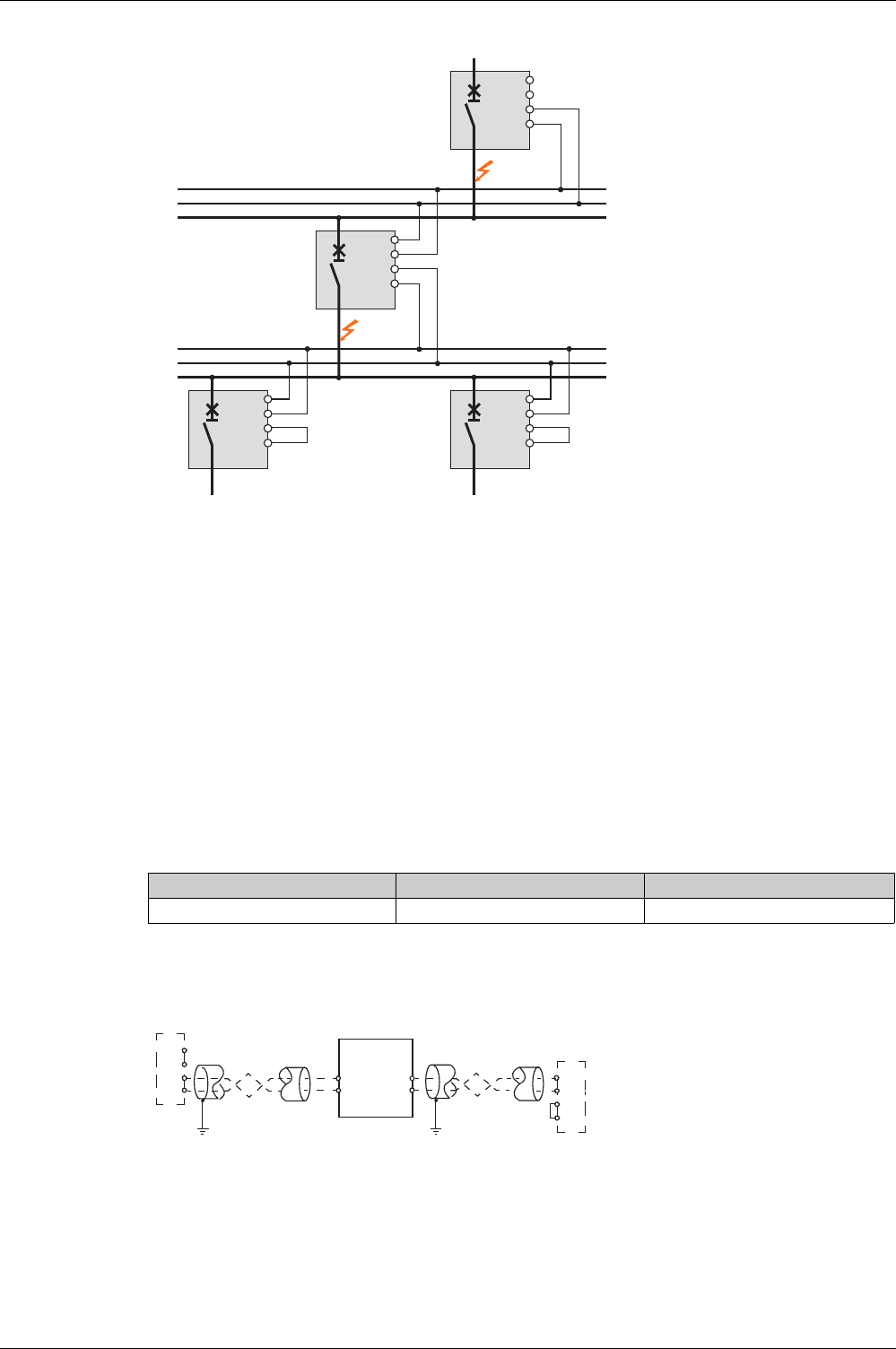
Protection Functions
DOCA0102EN-00 05/2016 81
NOTE: On device A, the tsd and tg tripping delays must not be set to zero because this would make
selectivity impossible.
Setting the Function
The following settings can be assigned to the ZSI input:
Ground-fault protection (Micrologic 6.0 X)
Short-time overcurrent protection
Both protections (factory setting)
Setting changes can be made as follows:
With Ecoreach software
By sending a setting command using the communication network. This function is password-protected.
Predefined Events
The function generates the following event:
Connection Principles
The figure below explains how the signal wire is connected to the Micrologic X control unit:
Q1 Upstream circuit breaker
Q2 Circuit breaker to be wired
Q3 Downstream circuit breaker
Z1 ZSI-OUT source
Z2 ZSI-OUT
Z3 ZSI-IN source
Z4 ZSI-IN
Z1
Z2
Z3
Z4
Z1
Z2
Z3
Z4
Z1
Z2
Z3
Z4
Z1
Z2
Z3
Z4
tsd = 0.3
tsd = 0.2
Fault 1
Fault 2
A
B
Upstream
circuit breaker
Downstream
circuit breaker
Event History Severity
ZSI test Diagnostic Low
Z1
Z2
Z3
Z4
Z1
Z2
Z3
Z4
Z1
Z2
Z3
Z4
3Q2Q1Q
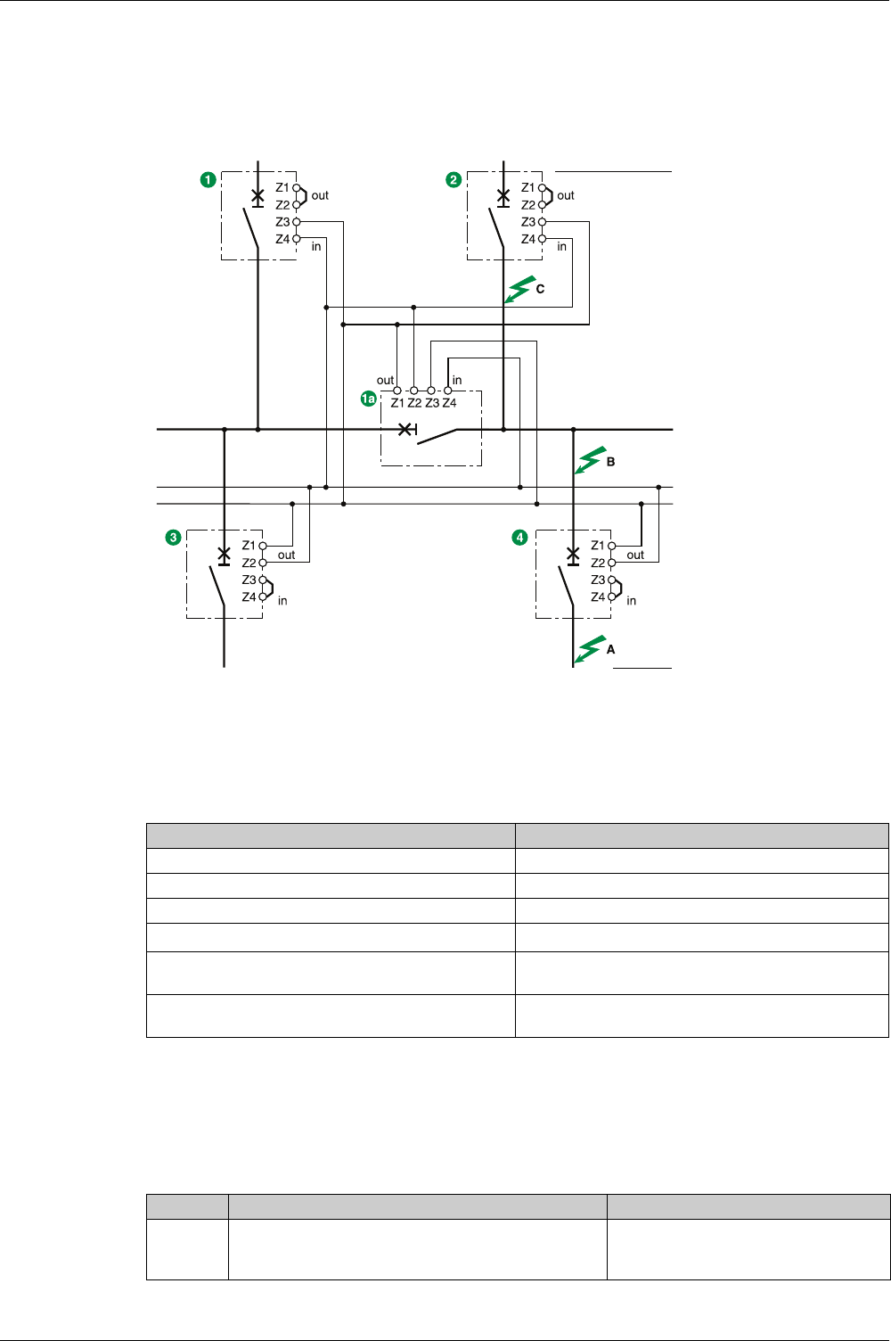
Protection Functions
82 DOCA0102EN-00 05/2016
NOTE: When ZSI is not used downstream, short circuit inputs Z3 and Z4. The setting of the short-time and
ground-fault protection time delays can be inhibited if this principle is not applied.
Multi-Source Distribution
If a number of circuit breakers are installed upstream (multi-source distribution), the same principles apply.
NOTE: Management of this configuration does not require any additional relays to ensure that ZSI is
controlled for the sources used.
Connection Wire Characteristics
The table below indicates the characteristics of the inter-device signal wire:
ZSI Interface Module
For more information about the ZSI Interface module, refer to the
ZSI Interface Module Instruction Sheet.
Testing the ZSI Function
The ZSI function can be tested using Ecoreach software, as follows:
tsd = 0.3 tsd = 0.3
tsd = 0.2
tsd = 0.1
Characteristics Values
Impedance 2.7 Ω per 300 m
Maximum length 300 m
Type of cable Shielded twisted (Belden 8441 or equivalent)
Permissible conductor cross-section 0.4–2.5 mm2
Interconnection limit on inputs Z3 and Z4 (to downstream
devices)
15 devices
Interconnection limit on outputs Z1 and Z2 (to upstream
devices)
5 devices
Step Action Result
1 Use Ecoreach to test the tripping time of short-time
overcurrent protection and/or ground-fault protection of
upstream Masterpact MTZ with a jumper between Z3 - Z4
The tripping time should be equal to tsd
and/or tg

Protection Functions
DOCA0102EN-00 05/2016 83
2 Use Ecoreach to test the tripping time of short-time
overcurrent protection and/or ground-fault protection of
downstream Masterpact MTZ
The tripping time should be equal to tsd
and/or tg
3 Remove Jumper between Z3-Z4 of upstream
Masterpact MTZ and connect wiring from downstream
Masterpact MTZ Z1-Z2.
–
4 Test wiring between downstream Masterpact MTZ and
upstream Masterpact MTZ by using Ecoreach connected
to downstream Masterpact MTZ
The trip cause indication LEDs of the
upstream Masterpact MTZ blink
Step Action Result

Protection Functions
84 DOCA0102EN-00 05/2016
Setting G uidelines
Section 3.3
Setting Guidelines
What Is in This Section?
This section contains the following topics:
Topic Page
Protection Setting Guidelines 85
Setting the Long-Time Overcurrent Protection (L or ANSI Code 49RMS) 87
Setting the Short-Time Overcurrent Protection (S or ANSI Code 51) 90
Setting the Instantaneous Overcurrent Protection (I or ANSI Code 50) 92
Selectivity 93

Protection Functions
DOCA0102EN-00 05/2016 85
Protection Setting Guidelines
Presentation
The setting of overcurrent protection relies on installation short-circuit and fault calculation. The setting
guideline cannot replace this calculation.
Masterpact MTZ circuit breakers with Micrologic X control units offer setting flexibility to ensure the
required overcurrent protection whilst maintaining selectivity and stability on transient phenomena when
necessary.
For each circuit, the installation designer needs to provide the following:
Iz: continuous current capacity of the circuit
Ifault min: minimum fault current at the end of the circuit depending on earthing system
Tmax short-circuit: maximum time for maximum short-circuit current
Guidelines are given for the following settings:
Ir: long-time overcurrent protection threshold
tr: long-time overcurrent protection time delay
Isd: short-time overcurrent protection threshold
tsd: short-time overcurrent protection time delay
Overcurrent Protection Setting Guidelines by Application
The following table gives the guidelines for overcurrent protection setting by application:
Application Micrologic 2.0 X Micrologic 5.0 X, 6.0 X, 7.0 X1
Secondary side of MV/LV transformer
(switchboard main incomer) with other
Masterpact or Compact NS 630–
3200 A downstream as feeder
Ir = Iz
tr ≤ 24 s
Isd ≤ Ifault min
No selectivity possible with feeders
except Compact NSX
Ir = Iz
tr ≤ 24 s
Isd ≤ Ifault min
tsd < Tmax short-circuit
tsd > tsd of downstream Masterpact or
Compact NS 630–3200 A
Ii enable: OFF
Secondary side of MV/LV transformer
(switchboard main incomer) without
other Masterpact or Compact
NS 630–3200 A downstream as
feeder
Ir = Iz
tr ≤ 24 s
Isd ≤ Ifault min
Ir = Iz
tr ≤ 24 s
Isd ≤ Ifault min
tsd = 0
Ii enable: ON
Ii mode: Standard
Ii = Isd
Generator output
with other Masterpact or Compact
NS 630–3200 A downstream as
feeder
Ir = Iz
tr ≤ 1 s
Isd ≤ Ifault min
No selectivity possible with feeders
except Compact NSX
Ir = Iz
tr ≤ 1 s
Isd ≤ Ifault min
tsd > tsd of downstream Masterpact or
Compact NS 630–3200 A
Ii enable: OFF
Generator output
without other Masterpact or Compact
NS 630–3200 A downstream as
feeder
Ir = Iz
tr ≤ 1 s
Isd ≤ Ifault min
Ir = Iz
tr ≤ 1 s
Isd ≤ Ifault min
tsd = 0
Ii enable: ON
Ii mode: Standard
Ii = Isd
Feeder with other Masterpact or
Compact NS 630–3200 A
downstream
Ir = Iz
tr ≤ 16 s
Isd ≤ Ifault min
No selectivity possible except with
Compact NSX
Ir = Iz
tr ≤ 16 s
Isd ≤ Ifault min
tsd > tsd of downstream circuit
breaker
Ii enable: OFF
1 Ground-fault protection and earth-leakage protection depend on the earthing system and local regulations. As a
general rule ground-fault and earth-leakage sensitivity should be as low as possible without being disturbed by
permanent or transient leakage current.The ground-fault and earth-leakage time delay ensures selectivity with
downstream devices.

Protection Functions
86 DOCA0102EN-00 05/2016
Feeder without other Masterpact or
Compact NS 630–3200 A
downstream as feeder
Ir = Iz
tr ≤ 16 s
Isd ≤ Ifault min
Ir = Iz
tr ≤ 16 s
Isd ≤ Ifault min
tsd = 0
Ii enable: ON
Ii mode: Standard
Ii = Isd
Power electronic (for example,
uninterruptible power supplies,
variable speed drives, photovoltaic
inverters) with no other circuit breaker
downstream
Ir = Iz
tr ≤ 8 s
Isd ≤ Ifault min
Ir = Iz
tr ≤ 16 s
Isd ≤ 1.5–2 x Ir
tsd = 0
Ii enable: ON
Ii mode: Fast
Ii = 2–3 x In
Application Micrologic 2.0 X Micrologic 5.0 X, 6.0 X, 7.0 X1
1 Ground-fault protection and earth-leakage protection depend on the earthing system and local regulations. As a
general rule ground-fault and earth-leakage sensitivity should be as low as possible without being disturbed by
permanent or transient leakage current.The ground-fault and earth-leakage time delay ensures selectivity with
downstream devices.
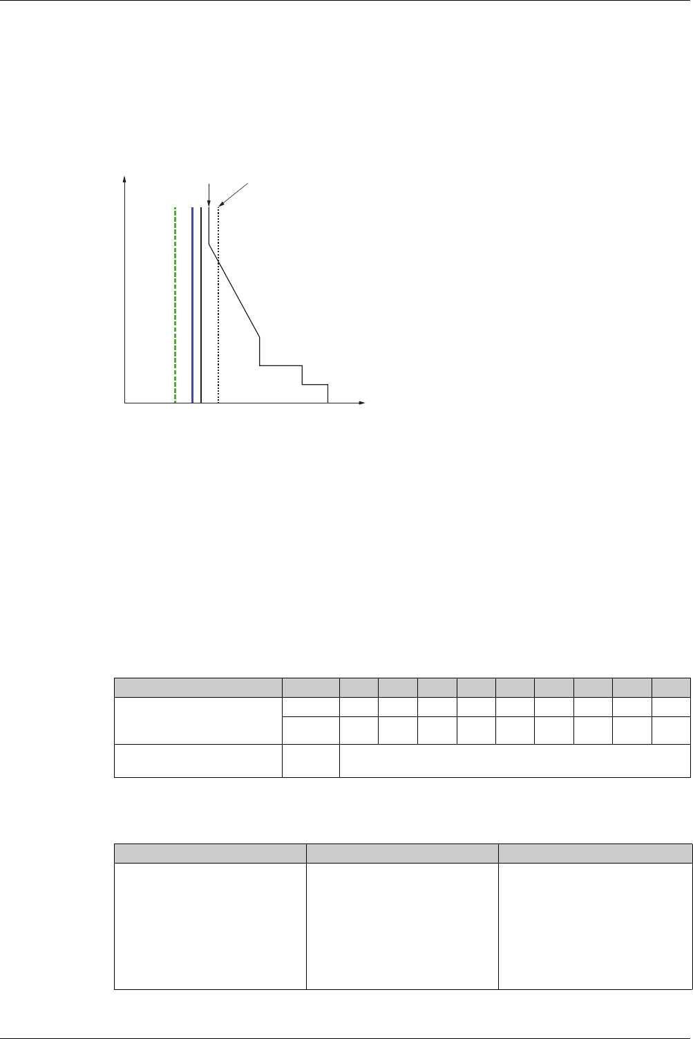
Protection Functions
DOCA0102EN-00 05/2016 87
Setting the Long-Time Overcurrent Protection (L or ANSI Code 49RMS)
Setting Guidelines for Ir
The Ir setting depends on the maximum expected current flow through the breaker and the maximum
current that can be withstood by the protected equipment (for example, cables, busbars, generators, and
transformers).
The installation rules, such as IEC 60364 Chapter 4.43 or similar national standards, require overload
protection for conductors as follows:
Ib Maximal load current
Ir Long time protection setting
Iz Continuous current-carrying capacity of the circuit
I2 Conventional operating current of the circuit breaker = 1.2 x Ir for Schneider Electronic control unit
I(A) Current through circuit breaker (phase(s) or neutral)
Setting Guidelines for tr
The tr setting depends on the maximum duration at maximum current and the maximum current that can
be withstood by the protected equipment (for example, cables, busbars, generators, and transformers).
Thermal memory: As described in long-time overcurrent protection
(see page 65)
, this protection function
is an overcurrent time-dependent protection with thermal memory. It operates as a thermal image, using
the heating and cooling model of a conductor. It can be considered as a first order thermal model with one
heating time constant.
The following table shows the relationship between the tr setting and the thermal time constant of the first
thermal model:
Summary of tr Setting Guidelines by Application
The following table gives the tr setting guidelines by application:
lb lr lz l (A)
1,45x lz
l
2
= 1,2 lr <= 1,45 lz
tr setting (s) Unit 0.5 124812 16 20 24
Equivalent time constant for
heating and cooling when control
unit is energized
seconds 14 28 56 112 224 335 447 559 671
minutes – – – – 3.5 5.6 7.5 9.3 11.2
Time constant for cooling when
control unit is not energized
minutes 5
Application Principle Usual value
Secondary side of MV/LV transformer
(switchboard main incomer)
Tie circuit breaker between two
switchboards
Tripping time according to circuit
thermal withstand for busbars, busbar
trunking, cable > 240 mm2:
Time constant > 11 min
tr = 24 s
When smaller cables are used in
parallel, a lower setting should be
used.
tr ≤ 24 s
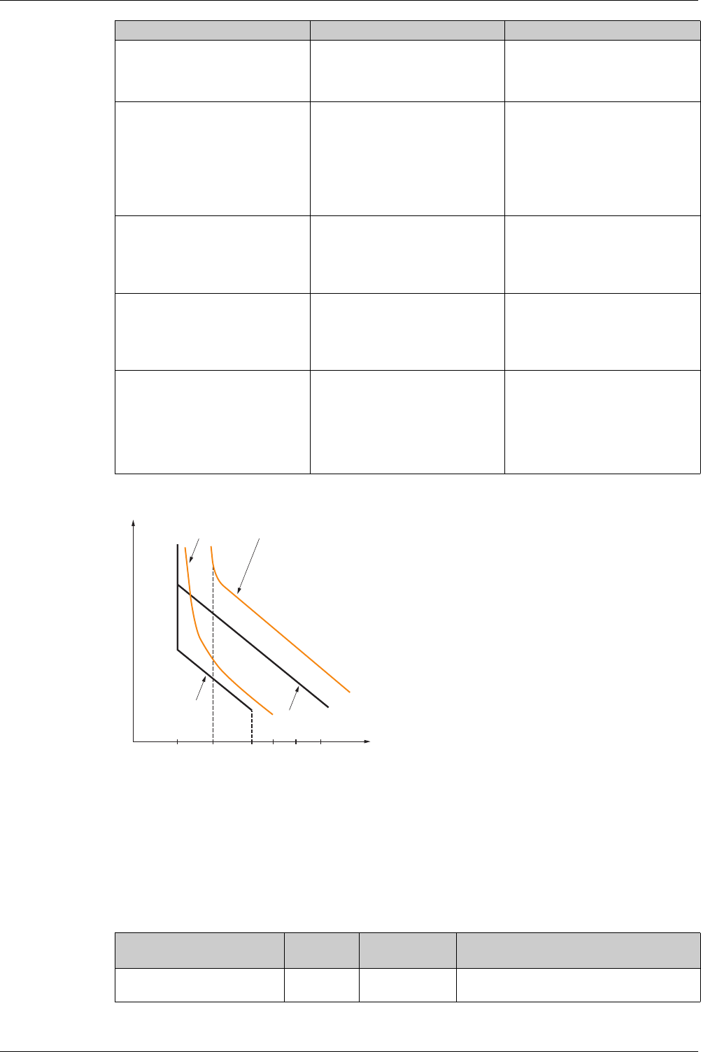
Protection Functions
88 DOCA0102EN-00 05/2016
Example of tr setting according to the application:
A Generator thermal limit
B Cable thermal limit
C Protection setting generator tLT (minimum notch)
D Protection setting cable tLT (maximum notch)
Neutral Protection Setting Guidelines
Some indications for setting neutral protection is given here. For more information refer to the neutral
protection section
(see page 76)
.
The following table indicates the long-time protection settings according to the neutral cable cross section:
Generators tr ≤ 1 s in order to achieve tripping
time < 30 s for 1.5 x Ir (IEC 60034-1
Clause 9.3.2)
tr ≤ 1 s
Feeder (cable or busbar trunking
protection)
Tripping time according to circuit
thermal withstand for busbars, busbar
trunking, cable > 240 mm2:
Time constant >11 min
tr = 24 s
To achieve selectivity with incomer, it
can be useful to reduce tr.
tr
≤ 24 s for busbar trunking or cable
≥240 mm²
≤ 16 s for lower cross section
cables
Primary side of LV/LV transformer According to cable or busbar trunking
withstand (transformer withstand is
generally higher)
To achieve selectivity with incomer, it
can be useful to reduce tr.
tr
≤ 24 s for busbar trunking or cable
≥240 mm²
≤ 16 s for lower cross section
cables
Power electronic (for example,
uninterruptible power supplies,
variable speed drives, photovoltaic
inverters)
Ir = Iz
tr ≤ 16 s
Isd ≤ Ifault min
tr
≤ 24 s for busbar trunking or cable
≥240 mm²
≤ 16 s for lower cross section
cables
Motors If motor is protected against overload
by a separate relay, long time setting
is done according to circuit thermal
withstand.
If the Micrologic ensures also motor
thermal overload, motor class must be
taken in consideration.
tr
= 12 s for a feeder
≥ 8 s for a class 10 motor
≥ 12 s for a class 20 motor
≥ 16 s for a class 30 motor
Application Principle Usual value
l
R
= In l
Z
l3 Ir
t
AB
C
D
Cross-sectional area of neutral
conductor
Harmonics
expected
Neutral protection
setting
Long-time protection
Less than cross-sectional area
of phase conductors
No 0.5 Ir is set according to Iz of cable, Ir applied to
neutral is divided by 2

Protection Functions
DOCA0102EN-00 05/2016 89
NOTE: On 3-pole circuit breakers the ENCT option must be declared.
NOTE: In IT systems, a distributed neutral conductor must be protected. (0.5, 1 or OSN position)
Equal to cross-sectional area of
phase conductors
No OFF No harmonics expected: the protection of
neutral is not necessary
Yes 1 Harmonics expected: the neutral must be
protected by the long-time protection, set as for
the phase protection
Greater than cross-sectional
area of phase conductors
No OFF No harmonics expected: the protection of
neutral is not necessary
Yes Oversized neutral Harmonics expected: the neutral must be
protected by the long-time protection, set as for
the phase protection multiplied by 1.6 (OSN)
Cross-sectional area of neutral
conductor
Harmonics
expected
Neutral protection
setting
Long-time protection
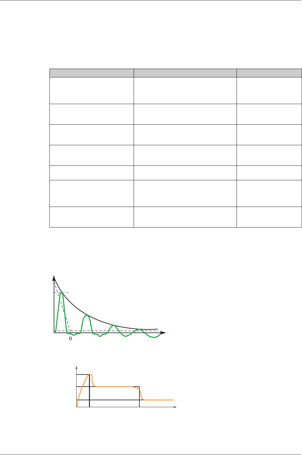
Protection Functions
90 DOCA0102EN-00 05/2016
Setting the Short-Time Overcurrent Protection (S or ANSI Code 51)
Settings Guideline
The Isd and tsd settings ensure that the short-time withstand current of protected equipment is not
exceeded.
Setting Guidelines for Isd
When LV/LV transformers are switched on, very high inrush currents are produced which must be taken
into account when choosing overcurrent protection devices. The peak value of the first current wave often
reaches 10 to 15 times the rated rms current of the transformer and may reach values of 20 to 25 times
the rated current even for transformers rated less than 50 kVA.
Example of inrush current: when transformer is switched on:
A 1st peak 10 to 25 x In
Example of inrush current of direct on line motor when started:
Application Principle Isd usual value
Secondary side of MV/LV transformer
(switchboard main incomer or tie
circuit breaker between two
switchboards)
Lower than minimum short-circuit or ground-
fault current at the end of the protected circuit.
Selectivity with downstream circuit breakers
10 x Ir
Generators Lower than minimum short-circuit or ground-
fault current supplied by the generator.
Selectivity with downstream circuit breakers
2–3 x Ir
Feeder with other Masterpact or
Compact NS 630–3200 A
downstream
Lower than minimum short-circuit or ground-
fault current at the end of the protected circuit.
Selectivity with downstream circuit breakers
10 x Ir
Feeder without other Masterpact or
Compact NS 630–3200 A
downstream
Lower than minimum short-circuit or ground-
fault current at the end of the protected circuit.
Selectivity with downstream circuit breakers
10 x Ir
Primary side of LV/LV transformer Lower than minimum secondary short-circuit
current.
10 x Ir
Power electronic (for example,
uninterruptible power supplies,
variable speed drives, photovoltaic
inverters)
Lower than minimum short-circuit or ground-
fault current at the end of the protected circuit.
Lower setting possible as no selectivity or
transient current is expected.
1.5–2 x Ir
Motors Lower than minimum short-circuit or ground-
fault current at the end of the protected circuit.
Lower setting possible above starting current.
10 x Ir
A
I
In
T
I
t
Id (5 – 8 In)
In
10 – 20 ms t
d
(1 – 10 s)

Protection Functions
DOCA0102EN-00 05/2016 91
Setting Guidelines for tsd
tsd is set according to selectivity.
Time-based selectivity is ensured between two circuit breakers when the supply side circuit breaker short-
time delay is at least one step higher than the load side short-time delay.
When downstream circuit breakers are Compact NSX circuit breakers, selectivity is always ensured with
Masterpact MTZ with Micrologic 2.0 X control units, and with Micrologic 5.0 X, 6.0 X and 7.0 X control
units, for all values of tsd.
Short-time tripping time can be definite time type (tripping time is independent of current level) or time
dependent with I2t = constant curve. This function allows the curve to be smoothed for low level
overcurrent, ensuring fast trip at high current. This is recommended for selectivity with fuses.
Application Principle tsd usual value
Secondary side of MV/LV transformer
(switchboard main incomer or tie
circuit breaker between two
switchboards)
Selectivity with downstream circuit
breakers
tsd > tsd of downstream power circuit
breaker (tsd = 0.2 s if installation
includes three levels of power circuit
breaker)
Feeder with selectivity with other
Masterpact MTZ or Compact > 630 A
downstream
Selectivity with downstream circuit
breakers
tsd > tsd of downstream power circuit
breaker (tsd = 0.1 s if installation
includes three levels of power circuit
breaker)
Feeder without selectivity with other
Masterpact MTZ or Compact > 630 A
downstream
No need for delayed short-time
protection
tsd=0s
Primary side of LV/LV transformer Stability during inrush.
Selectivity with downstream circuit
breakers
tsd = 0.1 s or
tsd > tsd of downstream power circuit
breaker, if any
Power electronic (Uninterrupted
power supplies, variable speed
drives, photovoltaic inverters, etc.)
No need for delayed short-time
protection
tsd=0s
Motors Stability during inrush tsd = 0 s or 0.1 s
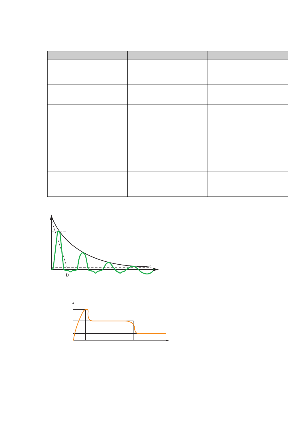
Protection Functions
92 DOCA0102EN-00 05/2016
Setting the Instantaneous Overcurrent Protection (I or ANSI Code 50)
Settings Guideline
Rules for Isd also apply to the Ii threshold.
Isd is set below the minimum value of short-circuit current and ground-fault in protected equipment:
Ii setting allows normal transient overcurrent inrush current for transformers:
A 1st peak 10 to 25 x In
Motor direct on line starting current:
Application Principle Usual value
Secondary side of MV/LV transformer
(switchboard main incomer)
Selectivity with downstream circuit
breakers
Ii enable : OFF if other Masterpact
downstream
Ii = 15 x In if Compact NSX only
downstream
Feeder with selectivity with other
Masterpact or Compact > 630 A
downstream
Same rule as for Isd Ii enable : OFF
Feeder without selectivity with other
Masterpact or Compact > 630 A
downstream
– Ii enable : ON
Ii type : Standard
Ii = 10-15 x In
Primary side of LV/LV transformer – Ii enable : OFF
Generators – Ii enable : OFF
Power electronic (for example,
uninterruptible power supplies,
variable speed drives, photovoltaic
inverters)
Lower than minimum short-circuit or
ground-fault at the end of the
protected circuit. Lower setting
possible as no selectivity or transient
current is expected.
Ii enable : ON
Ii type : Fast
Ii = 2 x In
Motor Lower than minimum short-circuit or
ground-fault at the end of the cable.
Lower setting possible above starting
current.
Ii enable : ON
Ii type : Fast
Ii ≥ 13 x Flc motor
A
I
In
T
I
t
Id (5 – 8 In)
In
10 – 20 ms t
d
(1 – 10 s)
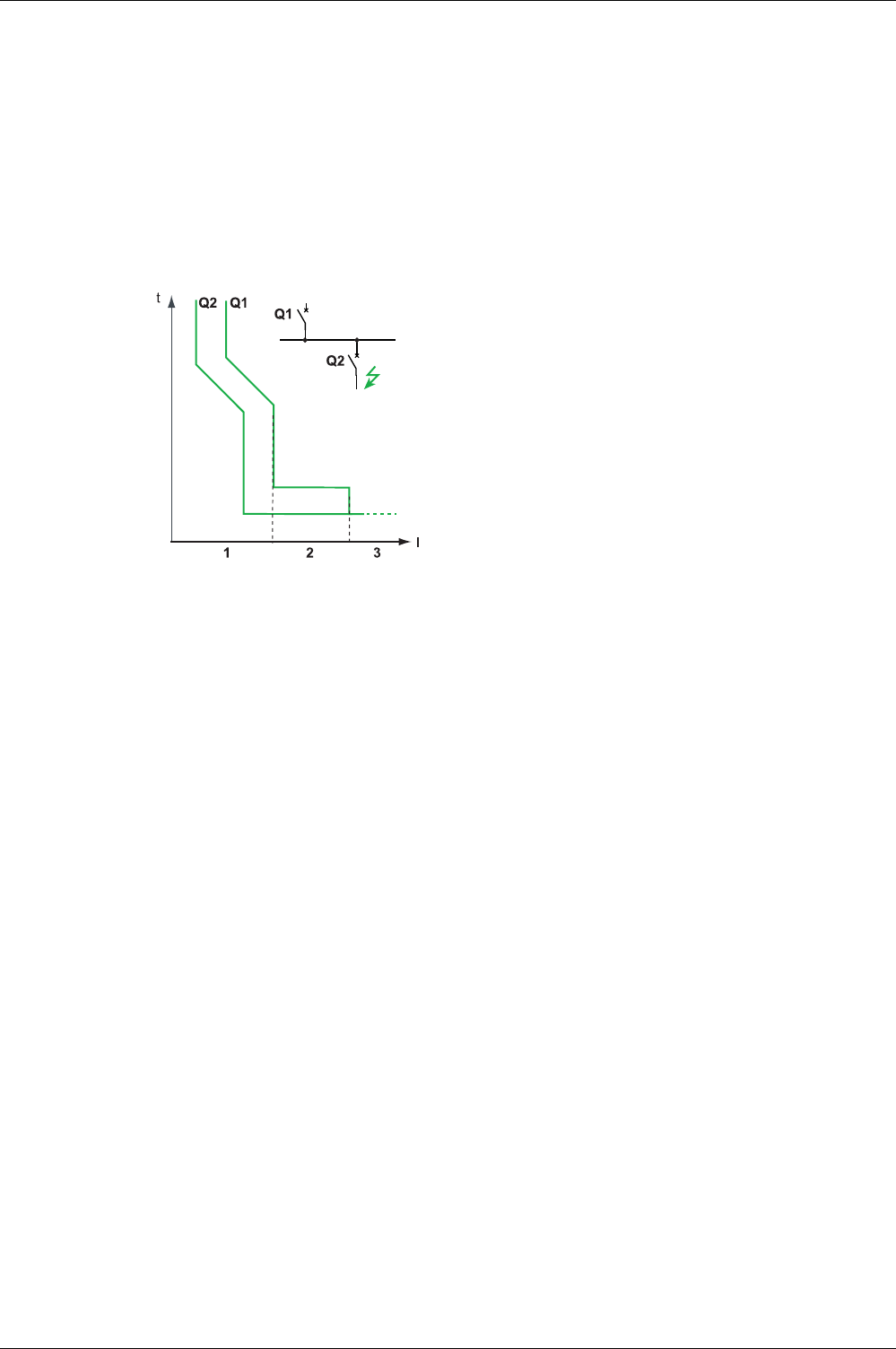
Protection Functions
DOCA0102EN-00 05/2016 93
Selectivity
Coordination Between Devices
Coordination between the upstream and downstream devices, especially selectivity, is essential to
optimize continuity of service. The large number of options for setting the protection functions on
Micrologic X control units improves the natural coordination between circuit breakers.
Three selectivity techniques can be used:
Current selectivity, which corresponds to staging of the long-time overcurrent protection threshold.
Time selectivity, which corresponds to staging of the short-time overcurrent protection threshold.
Energy selectivity, which corresponds to staging of the circuit breaker energy levels: this applies for high
intensity short-circuit currents.
Selectivity Rules
The selectivity rules depend on:
The type of control unit on the circuit breakers installed upstream and downstream: electronic or
thermal-magnetic.
The accuracy of the settings.
Selectivity of Overcurrent Protection
For overcurrent protection, the selectivity rules between electronic control units are as follows:
Current and time selectivity:
A ratio of Ir Q1/Ir Q2 greater than or equal to 1.3 is sufficient between the Ir threshold for long-time
protection of the control unit on the upstream circuit breaker Q1 and that of the control unit on the
downstream circuit breaker Q2.
The tr time delay for long-time protection of the control unit on the upstream circuit breaker Q1 is
identical or greater than that of the control unit on the downstream circuit breaker Q2.
A ratio of 1.5 is sufficient between the Isd threshold for short-time protection of the control unit on the
upstream circuit breaker Q1 and that of the control unit on the downstream circuit breaker Q2.
The tsd time delay for short-time protection of the control unit on the upstream circuit breaker Q1 is
greater than that of the control unit on the downstream circuit breaker Q2.
If the upstream circuit breaker is in the I2t off position, the downstream circuit breakers must not be
in the I2t on position.
Energy selectivity is provided by the circuit breaker design and build characteristics. The selectivity limit
can only be guaranteed by the manufacturer.
Ground-Fault Protection Selectivity
For ground-fault protection, only the rules for time selectivity should be applied to the Ig protection
threshold and tg time delay:
A ratio of 1.3 is sufficient between the Ig threshold for ground-fault protection of the control unit on the
upstream circuit breaker Q1 and that of the control unit on the downstream circuit breaker Q2.
The tg time delay for ground-fault protection of the control unit on the upstream circuit breaker Q1 is
greater than that of the control unit on the downstream circuit breaker Q2.
If the upstream circuit breaker is in theI2t off position, the downstream circuit breakers must not be in
theI2t on position.
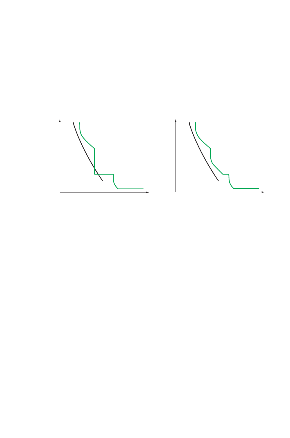
Protection Functions
94 DOCA0102EN-00 05/2016
Selectivity Limit
Depending on the staging of circuit breaker ratings and protection parameter settings, selectivity can be:
Limited (partial selectivity) up to a value lower than the maximum expected short-circuit current.
Total (total selectivity), performed irrespective of the value of the short-circuit current.
Selectivity Table
Schneider Electric provides selectivity tables showing the type of selectivity (partial or total) between each
circuit breaker for its entire range of circuit breakers (refer to the
Complementary Technical
Information Catalog
).
I2t ON/OFF Function
Use the I2t inverse time curve function to improve circuit breaker coordination. Use it when a protection
device using inverse time only is installed upstream or downstream, for example a fuse protection device.
I2t OFF I2t ON
t(s)
gG - 250 A
NS800N - Micrologic 5.0 A - 800 A
I (A)
t(s)
gG - 250 A
NS800N - Micrologic 5.0 A - 800 A
I (A)

DOCA0102EN-00 05/2016 95
Micrologic X
Metering Functions
DOCA0 102EN-00 05/2016
Metering Fu nctions
Chapter 4
Metering Functions
What Is in This Chapter?
This chapter contains the following sections:
Section Topic Page
4.1 Standard Metering Functions 96
4.2 Optional Metering Functions 129
Metering Functions
96 DOCA0102EN-00 05/2016
Standard Metering Fun ctions
Section 4.1
Standard Metering Functions
What Is in This Section?
This section contains the following topics:
Topic Page
Measurement Accuracy in Accordance with IEC 61557-12 97
Measurement Characteristics 102
Measurement Availability 107
Network Settings 113
Real-Time Measurements 114
Power Metering 117
Power Calculation Algorithm 120
Energy Metering 121
Harmonic Currents and Voltages 123
Power Quality Indicators 124
Power Factor PF and cos ϕ Measurement 126

Metering Functions
DOCA0102EN-00 05/2016 97
Measurement Accuracy in Accordance with IEC 61557-12
Measurements and Electrical Parameters Available on the Micrologic X Control Unit
Based on the measurement of line currents, neutral current, phase-to-phase voltages, and phase-to-
neutral voltages, the Micrologic X control unit displays the following parameters:
RMS values of currents and voltages
Active, reactive, and apparent powers
Active, reactive, and apparent energies
Power factor
Frequency
Unbalance and THD of voltages and currents
Average and predicted values are calculated for the main basic electrical parameters.
The maximum and minimum values are time stamped and logged in the Micrologic X non-volatile memory.
They can be reset as follows:
On the Micrologic X display screen
With Ecoreach software
With the Masterpact MTZ mobile App
By a remote controller using the communication network
Electrical parameters, which are refreshed once a second, can be displayed as follows:
On the Micrologic X display screen, at Home → Measures
(see page 45)
With Ecoreach software
With the Masterpact MTZ mobile App
By a remote controller using the communication network
The availability of parameters depends on the type of interface used to display data. All parameters are not
displayed on all interfaces
(see page 107)
.
An optional external 24 Vdc supply or VPS module is mandatory to measure and display parameters,
including energy counters, for currents below 20% of the rated current.
Measurement Accuracy
Power and energy metering accuracy in Masterpact MTZ with Micrologic X control unit is classified as
Class 1, according to IEC 61557-12. This standard specifies performance requirements of measuring and
monitoring devices that measure and monitor the electrical parameters within electrical distribution
systems. It covers both performance measuring devices with external sensors (PMD-S), such as current
and/or voltage transformers, for example, stand-alone power meters, and performance measuring devices
with embedded sensors (PMD-D), for example, circuit breakers.
Masterpact MTZ, with Micrologic X control unit and embedded sensors, is a PMD-DD device with Class 1
accuracy, according to IEC 61557-12 for power and energy metering. It complies with the requirements of
K70 temperature class, according to table 6 of IEC 61557-12.
The IEC 61557-12 standard defines the following three levels of uncertainty that need to be checked to
establish accuracy class:
Intrinsic uncertainty
(see page 98)
Operating uncertainty
(see page 99)
Overall system uncertainty
(see page 100)
A PMD-DD device avoids overall system uncertainty and variation, thanks to its embedded sensors and
wiring.
Measured Electrical Parameter Uncertainty
Uncertainty is the estimated percentage by which a measured electrical parameter may differ from the true
electrical parameter. In the context of this standard, the total uncertainty of a measured electrical
parameter depends on the instrument, the environment, and other elements to be considered.
The graphic below shows the total uncertainty of a measured electrical parameter made by:
A PMD-D device, with embedded sensors
A PMD-S device, with external sensors
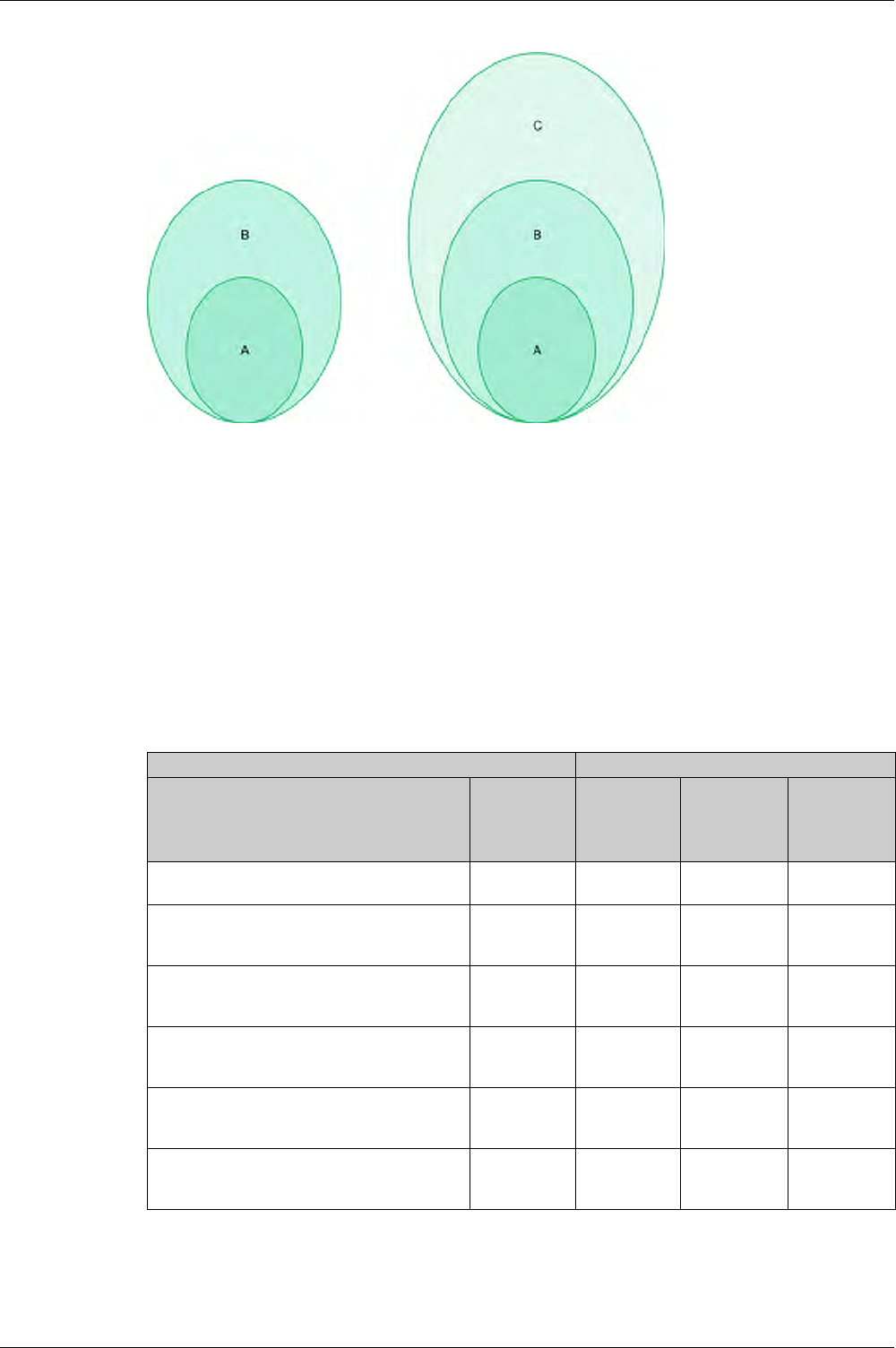
Metering Functions
98 DOCA0102EN-00 05/2016
Intrinsic Uncertainty: IEC 61557-12 definition
Intrinsic uncertainty is the uncertainty of a measuring instrument when used under reference conditions. In
the context of this standard, it is a percentage of the measured electrical parameter defined within the rated
range of the measuring instrument.
For Masterpact MTZ with Micrologic X control unit, the main values are current and power factor.
The following table indicates the current range for different Masterpact MTZ circuit breakers, to ensure
uncertainty is less than or equal to 1%:
PMD-D device, with embedded sensors PMD-S device, with external sensors
A Uncertainty under reference conditions: Intrinsic uncertainty according to IEC 61557-12
B Variations due to influence quantity: Operating Uncertainty according to IEC 61557-1;
Measurement uncertainty according to IEC 61000-4-30
C Overall system uncertainty according to IEC 61557-12
Current values for active power with 1% uncertainty (in A) Masterpact
Description of current value Current value
as percentage
of maximal
load current
MTZ1 MTZ2 MTZ3
Lowest value of the current at which the circuit
breaker starts and continues to register
Ist = 0.04% Ib 1.6 A 1.6 A 3.2 A
Lowest value of the current to ensure accuracy
less than or equal to 1.5% for active power and
energy
5% Ib 20 A 20 A 40 A
Lowest value of the current to ensure accuracy
less than or equal to 1% for active power and
energy with PF = 1
10% Ib 40 A 40 A 80 A
Lowest value of the current to ensure accuracy
less than or equal to 1% for active power and
energy with PF = 0.5 Ind to 0.8 Cap
20% Ib 80 A 80 A 160 A
Value of current in accordance with which the
relevant performance of a direct connected PMD
(PMD Dx) is fixed
Ib 400 A 400 A 800 A
Highest value of current at which the
Masterpact MTZ meets the uncertainty
requirements of this standard
Imax 1600 A x 1.2 4000 A x 1.2 6300 A x 1.2
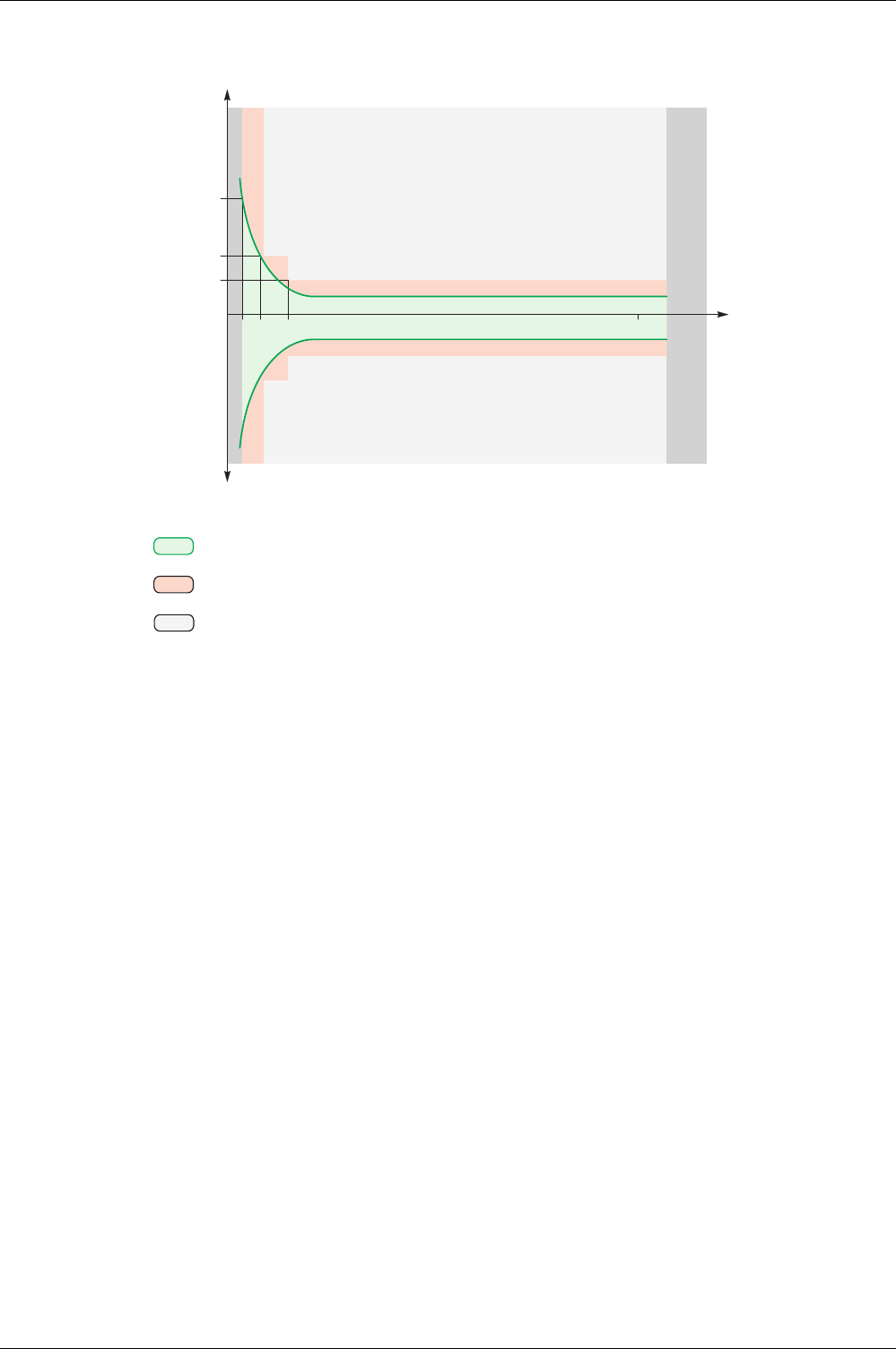
Metering Functions
DOCA0102EN-00 05/2016 99
Intrinsic uncertainty for active power and energy versus current. Example graph for Masterpact MTZ2
Operating Uncertainty
IEC 61557-12 defines operating uncertainty as uncertainty under the rated operating conditions.
IEC 61557-12 specifies tests and maximum variation of uncertainty according to the following influence
quantities:
Ambient temperature (T°)
Frequency, unbalance, harmonics, EMC
For Masterpact MTZ with Micrologic X control unit, the main influence quantity is temperature.
Masterpact MTZ devices are designed to carry high currents, which induce self-heating. The measurement
has been designed to offer high stability in a wide range of temperatures.
Effect of Temperature on Masterpact MTZ Measurement System
The temperature variation around the internal current transformer and the Micrologic X control unit,
between minimum current and nominal current load can be up to 90 K. The effect of temperature on
measurement accuracy has been carefully managed to ensure an operating ambient temperature of
between -25 °C and 70 °C (-13 °F and 158 °F).
Masterpact MTZ2
Standard
Out of standard
Istart
Imin 1.5 %
Imin 1 % Out of
range
Current (A)
40201.6 4000
No
load
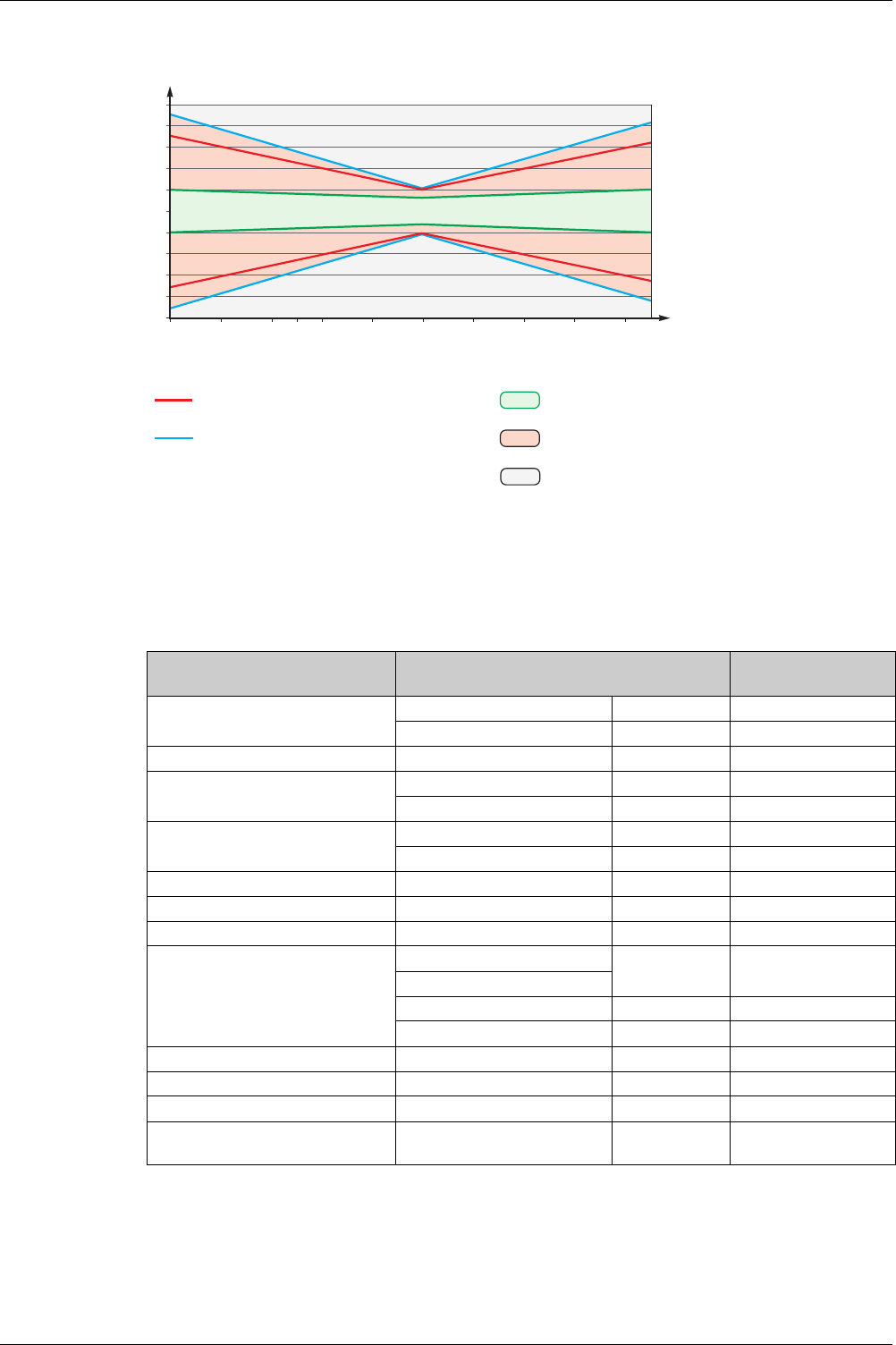
Metering Functions
100 DOCA0102EN-00 05/2016
Effect of Electromagnetic Compatibility (EMC) and Other Influence Quantities on Masterpact MTZ Measurement Performance
Masterpact MTZ with Micrologic X control unit offers a high immunity to influence quantities, with a low
operating uncertainty for active power, as specified by Class 1, for a wide range of operating conditions.
The following table summarizes standard requirements and Masterpact MTZ performance with regard to
influence quantities for active power:
Overall System Uncertainty
IEC 61557-12 defines overall system uncertainty as uncertainty including the instrumental uncertainty of
several separated instruments (for example, sensors, wires, measuring instruments) under the rated
operating conditions.
Uncertainty min/max PF 1
Uncertainty min/max PF 0.5
Masterpact MTZ
Standard
Out of standard
-25 -15 -5
0
1
2
3
4
5
-5
-4
-3
-2
-1
50 152535455565
Accuracy (%)
Temperature (°C)
Masterpact MTZ
Influence quantity Table 9 IEC 61557-12 PMD DD Cl 1
additional uncertainty variation tolerance
Masterpact MTZ
additional uncertainty
Ambient temperature PF 1 0.05% / K < 0.01% / K
PF 0.5 Ind 0.07% / K < 0.01% / K
Auxiliary power supply 24 Vdc ±15% 0.1% 0%
Voltage PF 1: 80% / 120% Un 0.7% 0%
PF 0,5 Ind: 80% / 120% Un 1% 0%
Frequency PF 1: 49–51 Hz / 59–61 Hz 0.5% 0%
PF 0.5: 49–51 Hz / 59–61 Hz 0.7% 0%
Reversed phase sequence 1.5% 0%
Voltage unbalance 0 to 10% 2% 0%
Phase missing 1 or 2 phase missing 2% 0%
Harmonics in current and voltage 10% Un 5th 0.8% < 0.1%
20% Imax 5th
Odd harmonic in current 3% < 0.1%
Sub harmonic in current 3% < 0.1%
Common mode voltage rejection 0–690 Vac / ground 0.5% 0%
Permanent ac magnetic induction IEC 61326 2% 0%
Electromagnetic RF fields IEC 61326 2% < 1%
Conducted disturbances induced by
RF fields
IEC 61326 2% < 1%