Schneider Electric IndustrieS NX2TO7 Control Units User Manual Micrologic X Control Unit User Guide 05 2016
Schneider Electric Industrie SAS Control Units Micrologic X Control Unit User Guide 05 2016
Contents
- 1. Users Manual (Statement)_rev.pdf
- 2. Users Manual-1.pdf
- 3. Users Manual-2.pdf
Users Manual-2.pdf

Metering Functions
DOCA0102EN-00 05/2016 101
For Masterpact MTZ devices, the sensors are embedded in the device for applications up to 690 Vac and
the overall uncertainty is equal to the operating uncertainty.

Metering Functions
102 DOCA0102EN-00 05/2016
Measurement Characteristics
Presentation
The following tables indicate the measurements available and specify the following information for each
measurement:
Unit
Measurement range
Accuracy
Accuracy range
Current
NOTE: The accuracy range is for the current range: 0.2–1.2 In.
Current Unbalance
NOTE: The accuracy range is for the current range: 0.2–1.2 In.
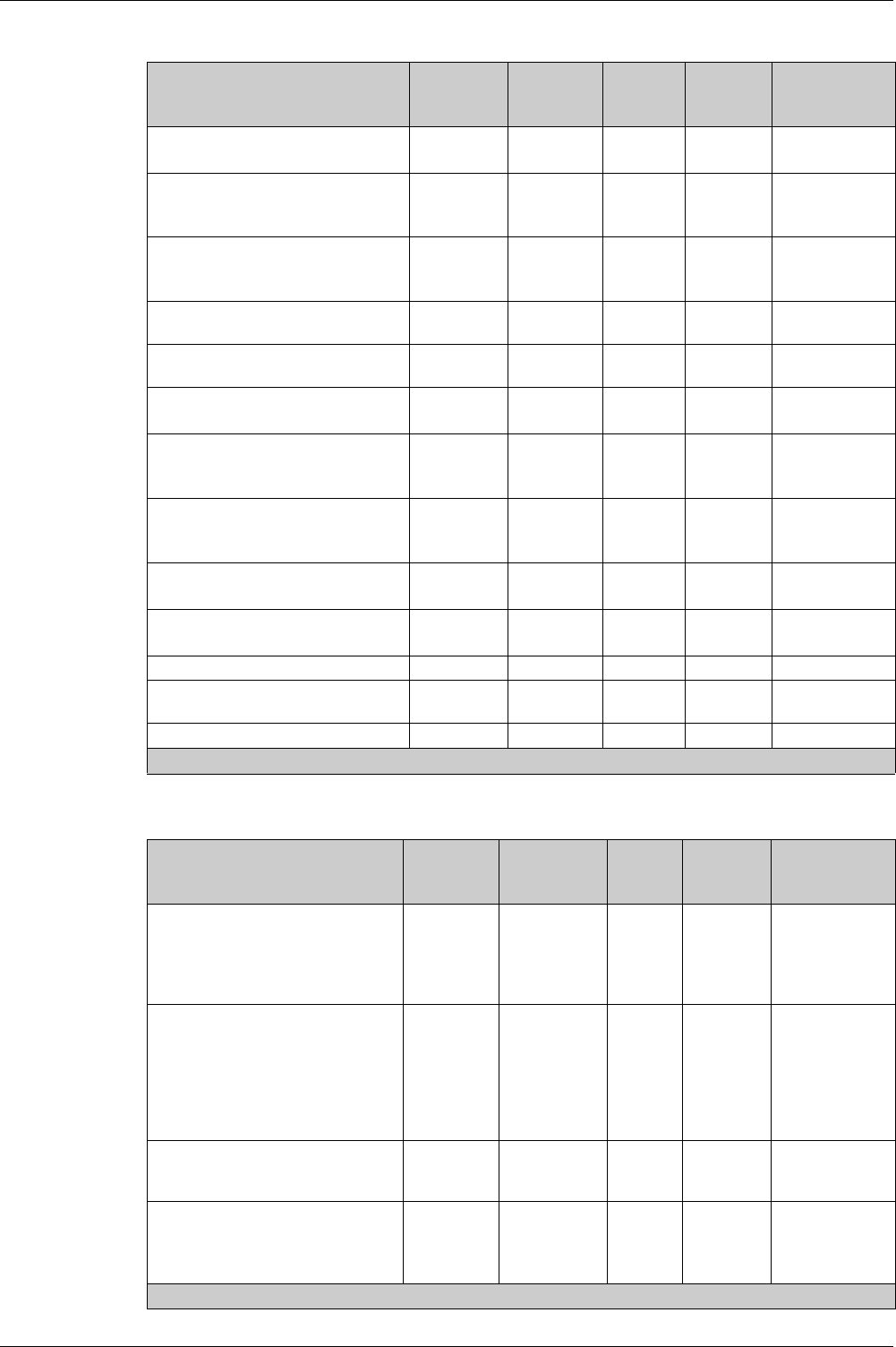
Measurement Unit Range Accuracy Accuracy range
RMS current on phases 1, 2, 3
Maximum RMS current on phases 1, 2, 3 (I1 MAX, I2
MAX, I3 MAX)
Maximum value (MAXMAX) of all phase currents
Minimum RMS current on phases 1, 2, 3 (I1 MIN, I2 MIN,
I3 MIN)
Minimum value (MINMIN) of all phase currents
A 0–20 In +/-0.5% MTZ1 : 40–1600 x 1.2 In
MTZ2 : 40–4000 x 1.2 In
MTZ3 : 80–6300 x 1.2 In
RMS current on neutral 1
Maximum RMS current on neutral IN MAX 1
Minimum RMS current on neutral IN MIN 1
A 0–20 In +/-1% MTZ1 : 40–1600 x 1.2 In
MTZ2 : 40–4000 x 1.2 In
MTZ3 : 80–6300 x 1.2 In
Average of 3 phase RMS currents
Maximum average of 3 phase RMS currents Iavg MAX
Minimum average of 3 phase RMS currents Iavg MIN
A 0–20 In +/-0.5% MTZ1:40–1600 x 1.2 In
MTZ2:40–4000 x 1.2 In
MTZ3:80–6300 x1.2 In
RMS current on ground 2
Maximum/minimum RMS current on ground 2
A 0–20 In 5% MTZ1:40–1600 x 1.2 In
MTZ2:40–4000 x 1.2 In
MTZ3:80–6300 x1.2 In
Earth-leakage current measurement 3
Maximum/minimum value of the earth-leakage current 3
A 0–30 A 10% 0.1–30 A
1 Applies to 4-pole circuit breakers or 3-pole circuit breakers with ENCT wired and configured.
2 Applies to Micrologic 6.0 X control unit
3 Applies to Micrologic 7.0 X control unit
Measurement Unit Range Accuracy Accuracy
range
Phase current unbalance on phase 1, 2, 3 (I1 unbal, I2 unbal, I3
unbal)
Maximum of 3 phase current unbalances (l1 unbal MAX,
I2 unbal MAX, I3 unbal MAX)
Maximum of maximum of 3 phase current unbalances (MAXMAX)
% 0–100% +/-5 0–100%

Metering Functions
DOCA0102EN-00 05/2016 103
Voltage
Voltage Unbalance
NOTE: The accuracy range is for the voltage range: 208–690 x 1.2 Vac.
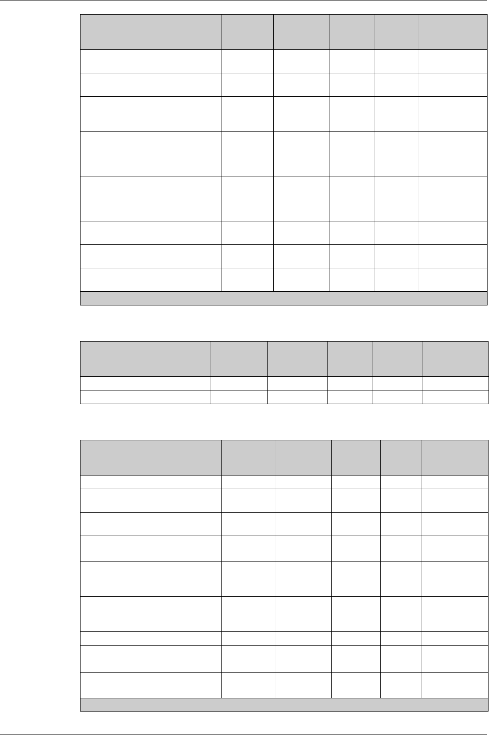
Measurement Unit Range Accuracy Accuracy range
RMS phase-to-phase V12, V23, V31 voltage measurements 1
Maximum RMS phase-to-phase voltages V12 MAX L-L,
V23 MAX L-L, V31 MAX L-L 1
Minimum RMS phase-to-phase voltages V12 MIN L-L,
V23 MIN L-L, V31 MIN L-L1
Maximum of the maximum phase-to-phase voltages (V12,
V23, V31)
Minimum of the minimum phase-to-phase voltages (V12, V23,
V31)
V 0–1,150 V +/-0.5% 208–690 x 1.2 V
RMS phase-to-neutral V1N, V2N, V3N voltage
measurements1
Maximum RMS phase-to-neutral voltages V1N MAX L-N, V2N
MAX L-N, V3N MAX L-N 1
Minimum RMS phase-to-neutral voltages V1N MIN L-N, V2N
MIN L-N, V3N MIN L-N 1
Maximum of the maximum phase-to-neutral voltages (V1N,
V2N, V3N) 1
Minimum of the minimum phase-to-neutral voltages (V1N,
V2N, V3N) 1
V 0–660 V +/-0.5% 120–400 x 1.2 V
Average of 3 RMS phase-to-phase voltages Vavg:
(V12+V23+V31)/3
Maximum of average of 3 RMS phase-to-phase voltages
Vavg MAX: (V12+V23+V31)/3
Minimum of average of 3 RMS phase-to-phase voltages
Vavg MIN: (V12+V23+V31)/3
V 0–1,150 V +/-0.5% 208–690 x 1.2 V
1 Applies to 4-pole circuit breakers or 3-pole circuit breakers with ENVT wired and configured.
Measurement Unit Range Accuracy Accuracy
range
Phase-to-phase voltage unbalances V12unbal L-L, V23unbal L-
L, V31unbal L-L 1
Maximum of 3 phase-to-phase voltage unbalances
V12unbal MAX L-L, V23unbal MAX L-L, V31unbal MAX L-L1
Maximum of maximum (MAXMAX) of 3 phase-to-phase voltage
unbalances 1
% 0–100% +/-0.5 0–10%
Phase-to-neutral voltage unbalances V1Nunbal L-N, V2Nunbal L-
N, V3Nunbal L-N unbalance measurements 1
Maximum of 3 phase-to-neutral voltage unbalances
V1Nunbal MAX L-L, V2Nunbal MAX L-L, V3Nunbal MAX L-L 1
Maximum of maximum (MAXMAX) of 3 phase-to-neutral voltage
unbalances1
% 0–100% +/-0.5 0–10%
1 Applies to 4-pole circuit breakers or 3-pole circuit breakers with ENVT wired and configured.

Metering Functions
104 DOCA0102EN-00 05/2016
Power
NOTE: The power measurement range according to IEC 61557-12 is defined by current range, voltage,
and power factor values.
Power Factor PF and cos ϕ
Measurement Unit Range Accuracy Accuracy
range
Active power on phase 1, phase 2, phase 3 1
Maximum active power on phase 1, phase 2, phase 3 P1 MAX,
P2 MAX, P3 MAX1)
Minimum active power on phase 1, phase 2, phase 3 P1 MIN,
P2 MIN, P3 MIN 1
kW -16,000–
16,000 kW
+/-1% 2
Total active power Ptot
Maximum total active power Ptot MAX
Minimum total active power Ptot MIN
kW -16,000–
16,000 kW
+/-1% 2
Reactive power on phase 1, phase 2, phase 3 Q1, Q2, Q3 1
Maximum reactive power on phase 1, phase 2, phase 3 Q1 MAX,
Q2 MAX, Q3 MAX 1
Minimum reactive power on phase 1, phase 2, phase 3 Q1 MIN,
Q2 MIN, Q3 MIN 1
kVAR -16,000–
16,000 kVAR
+/-2% 2
Total reactive power Qtot
Maximum total reactive power Qtot MAX
Minimum total reactive power Qtot MIN
kVAR -16,000–
16,000 kVAR
+/-1% 2
Apparent power on phase 1, phase 2, phase 3 S1, S2, S3 1
Maximum apparent power on phase 1, phase 2, phase 3 S1 MAX,
S2 MAX, S3 MAX 1
Minimum apparent power on phase 1, phase 2, phase 3 S1 MIN,
S2 MIN, S3 MIN 1
kVA 0–16,000 kVA +/-1% 2
Total apparent power Stot
Maximum total apparent power Stot MAX
Minimum total apparent power Stot MIN
kVA 0–16,000 kVA +/-1% 2
Fundamental reactive power on phase 1, phase 2, phase 3
Qfund 1, Qfund 2, Qfund 31
Maximum fundamental reactive power on phase 1, phase 2,
phase 3 Qfund 1 MAX, Qfund 2 MAX, Qfund 3 MAX 1
Minimum fundamental reactive power on phase 1, phase 2, phase
3 Qfund 1 MIN, Qfund 2 MIN, Qfund 3 MIN 1
kVAR -16,000–
16,000 kVAR
+/-1% 2
Total fundamental reactive power Qfundtot
Maximum total fundamental reactive power Qfundtot MAX
Minimum total fundamental reactive power Qfundtot MIN
kVAR -16,000–
16,000 kVAR
+/-1% 2
1 Applies to 4-pole circuit breakers or 3-pole circuit breakers with ENVT wired and configured.
2 The power measurement range according to IEC 61557-12 is defined by current range, voltage, and power factor
values.
Measurement Unit Range Accuracy Accuracy
range
Total power factor PF
Maximum total power factor PF MAX
Minimum total power factor PF MIN
– -1.00–
1.00
+/-0.02 0.5 ind -
0.8 cap
Power factors on phase 1, phase 2, phase 3 PF1, PF2, PF3 1
Maximum power factor on phase 1, phase 2, phase 3 PF1 MAX,
PF2 MAX, PF3 MAX 1
Minimum power factor on phase 1, phase 2, phase 3 PF1 MIN,
PF2 MIN, PF3 MIN 1
– -1.00–
1.00
+/-0.02 0.5 ind -
0.8 cap
1 Applies to 4-pole circuit breakers or 3-pole circuit breakers with ENVT wired and configured.

Metering Functions
DOCA0102EN-00 05/2016 105
NOTE: The accuracy for the power factor measurement range according to IEC 61557-12 is defined by
current range and voltage values.
Total Harmonic Distortion of Currents and Voltages
Frequency
Energy Meters
Total fundamental power factor cos ϕ
Maximum total fundamental power factor cos ϕ MAX
Minimum total fundamental power factor cos ϕ MIN
– -1.00–
1.00
+/-0.02 0.5 ind -
0.8 cap
cos ϕ 1, cos ϕ 2, cos ϕ 3 on phase 1, phase 2, phase 3 1
Maximum cos ϕ 1 MAX, cos ϕ 2 MAX, cos ϕ 3 MAX on phase
1, phase 2, phase 31
Minimum cos ϕ 1 MIN, cos ϕ 2 MIN, cos ϕ 3 MIN on phase 1,
phase 2, phase 31
– -1.00–
1.00
+/-0.02 0.5 ind -
0.8 cap
Measurement Unit Range Accuracy Accuracy
range
1 Applies to 4-pole circuit breakers or 3-pole circuit breakers with ENVT wired and configured.
Measurement Unit Range Accuracy Accuracy range
Total harmonic distortion (THD) of current on phase 1,
phase 2, phase 3 THD(I1), THD(I2), THD(I3)
Maximum total harmonic distortion (THD) of current
on phase 1, phase 2, phase 3 THD(I1) MAX, THD(I2)
MAX, THD(I3) MAX
Minimum total harmonic distortion (THD) of current on
phase 1, phase 2, phase 3 THD(I1) MIN, THD(I2)
MIN, THD(I3) MIN
% 0–1,000% +/-1.5 0–100%
when I > 80 A
+/-1.5 x THD/100 100–200%
Total harmonic distortion (THD) of phase-to-phase
voltage THD(V12) L-L, THD(V23) L-L, THD(V31) L-L
Maximum total harmonic distortion (THD) of phase-to-
phase voltage THD(V12) MAX L-L, THD(V23) MAX L-
L, THD(V31) MAX L-L
Minimum total harmonic distortion (THD) of phase-to-
phase voltage THD(V12) MIN L-L, THD(V23) MIN L-
L, THD(V31) MIN L-L
% 0–1,000% +/-0.6 0–20%
when V > 208 V
Total harmonic distortion (THD) phase-to-neutral
voltage THD(V1N) L-N, THD(V2N) L-N, THD(V3N) L-
N 1
Maximum total harmonic distortion (THD) phase-to-
neutral voltage THD(V1N) MAX L-N, THD(V2N) L-L
MAX L-N, THD(V3N) MAX L-N 1
Minimum total harmonic distortion (THD) phase-to-
neutral voltage THD(V12) MIN L-N, THD(V2N) MIN L-
N, THD(V31) MIN L-N 1
% 0–1,000% +/-0.6 0–20%
when V > 120 V
Measurement Unit Range Accuracy Accuracy
range
Frequency
Maximum frequency
Minimum frequency
Hz 15–440 Hz +/-0.2% 45–65 Hz
Measurement Unit Range Accuracy Accuracy range
Active energy Ep, EpIn delivered, and EpOut
received
kWh -10,000,000 to
10,000,000
+/-1% 1
Reactive energy Eq, EqIn delivered, and EqOut
received
kVARh -10,000,000 to
10,000,000
+/-2% 1
1 The energy measurement range according to IEC 61557-12 is defined by current range, voltage, and power factor
values.

Metering Functions
106 DOCA0102EN-00 05/2016
NOTE: The energy measurement range according to IEC 61557-12 is defined by current range, voltage,
and power factor values.
Apparent energy Es kVAh -10,000,000 to
10,000,000
+/-1% 1
Measurement Unit Range Accuracy Accuracy range
1 The energy measurement range according to IEC 61557-12 is defined by current range, voltage, and power factor
values.

Metering Functions
DOCA0102EN-00 05/2016 107
Measurement Availability
Presentation
Measurements can be displayed through the following interfaces:
The Micrologic X display screen
The Masterpact MTZ mobile App
The FDM128
The Ecoreach software
The communication network
The following tables indicate which measurements are displayed on each interface.
Current
Current Unbalance
Measurement Micrologic X
HMI
Masterpact
MTZ mobile
App
FDM128 Ecoreach
software
Communication
Phase I1, I2, I3 current measurements X X X X X
Maximum phase current values I1
MAX, I2 MAX, I3 MAX
XXXXX
Maximum value (MAXMAX) of all
phase currents
–X–XX
Minimum phase current values I1 MIN,
I2 MIN, I3 MIN
–X–XX
Minimum value (MINMIN) of all phase
currents
–X–XX
Neutral IN current measurement 1XX–XX
Maximum neutral current value IN
MAX1
XX–XX
Minimum neutral current value IN MIN1–X–XX
Average current Iavg measurements X X X X X
Maximum average current value Iavg
MAX
–XXXX
Minimum average current value Iavg
MIN
–X–XX
Ground-fault current measurement 2–X–XX
Maximum/minimum value of the
ground-fault current 2
–X–XX
Earth-leakage current measurement 3–X–XX
Maximum/minimum value of the earth-
leakage current 3
–X–XX
1 With 4-pole circuit breakers or 3-pole circuit breakers with ENCT wired and configured.
2 Applies to Micrologic 6.0 X control unit
3 Applies to Micrologic 7.0 X control unit
Measurement Micrologic X
HMI
Masterpact
MTZ mobile
App
FDM128 Ecoreach
software
Communication
Phase current unbalance
measurements I1 unbal, I2 unbal,
I3 unbal
XX XX
Maximum values of phase current
unbalances l1 unbal MAX,
I2 unbal MAX, I3 unbal MAX
XX XX
Maximum value (MAXMAX) of all
phase current unbalances
–X XX
Metering Functions
108 DOCA0102EN-00 05/2016
Voltage
Voltage Unbalance
Measurement Micrologic X
HMI
Masterpact
MTZ mobile
App
FDM128 Ecoreach
software
Communication
Phase-to-phase V12, V23, V31 voltage
measurements1
XX XX
Maximum values of phase-to-phase
voltages V12 MAX L-L, V23 MAX L-L,
V31 MAX L-L 1
XX XX
Minimum values of phase-to-phase
voltages V12 MIN L-L, V23 MIN L-L,
V31 MIN L-L (1)
XX XX
Maximum value of the maximum phase-
to-phase voltages (V12, V23, V31
–X XX
Minimum value of the minimum phase-
to-phase voltages (V12, V23, V31)
–X XX
Phase-to- neutral V1N, V2N, V3N
voltage measurements 1
XX XX
Maximum values of phase-to-neutral
voltages V1N MAX L-N, V2N MAX L-N,
V3N MAX L-N 1
XX XX
Minimum values of phase-to-neutral
voltages V1N MIN L-N, V2N MIN L-N,
V3N MIN L-N 1
XX XX
Maximum value of the maximum phase-
to-neutral voltages (V1N, V2N, V3N) 1
–X XX
Minimum value of the minimum phase-
to-neutral voltages (V1N, V2N, V3N) 1
–X XX
Average voltage Vavg measurements X X X X
Maximum average voltage value
Vavg MAX
–X XX
Minimum average voltage Vavg MIN – X X X
1 4-pole circuit breakers or 3-pole circuit breakers with ENVT wired and configured.
Measurement Micrologic X
HMI
Masterpact
MTZ mobile
App
FDM128 Ecoreach
software
Communication
Phase-to-phase voltage V12unbal L-L,
V23unbal L-L, V31unbal L-L and
phase-to-neutral voltage V1Nunbal L-
N, V2Nunbal L-N, V3Nunbal L-N
unbalance measurements 1
XX XX
Maximum values of phase-to-phase
voltage unbalances V12unbal MAX L-
L, V23unbal MAX L-L,
V31unbal MAX L-L and phase-to-
neutral voltage unbalances
V1Nunbal MAX L-L, V2Nunbal MAX L-
L, V3Nunbal MAX L-L 1
XX XX
Maximum values (MAXMAX) of all
phase-to-phase and phase-to-neutral
voltage unbalances
–X XX
Maximum values of phase-to-phase
voltage unbalances V12unbal MAX L-
L, V23unbal MAX L-L,
V31unbal MAX L-L1
XX XX
1 4-pole circuit breakers or 3-pole circuit breakers with ENVT wired and configured.

Metering Functions
DOCA0102EN-00 05/2016 109
Power
Maximum values (MAXMAX) of the
maximum of the phase-to-phase
voltage unbalances 1
–X XX
Phase-to-neutral voltage V1Nunbal L-
N, V2Nunbal L-N, V3Nunbal L-N
unbalance measurements 1
XX XX
Maximum values of phase-to-neutral
voltage unbalances V1Nunbal MAX L-
L, V2Nunbal MAX L-L,
V3Nunbal MAX L-L1
XX XX
Maximum values (MAXMAX) of the
maximum of the phase-to-neutral
voltage unbalances 1
–X XX
Measurement Micrologic X
HMI
Masterpact
MTZ mobile
App
FDM128 Ecoreach
software
Communication
1 4-pole circuit breakers or 3-pole circuit breakers with ENVT wired and configured.
Measurement Micrologic X
HMI
Masterpact
MTZ mobile
App
FDM128 Ecoreach
software
Communication
Active power measurements for each
phase P1, P2, P3 1
XX XX
Maximum values of active powers for
each phase P1 MAX, P2 MAX, P3 MAX
1
–X XX
Minimum values of active powers for
each phase P1 MIN, P2 MIN, P3 MIN 1
–X XX
Total active power measurement Ptot X X X X
Maximum value of total active power
Ptot MAX
XX XX
Minimum value of total active power
Ptot MIN
–X XX
Reactive power measurements for
each phase Q1, Q2, Q3 1
XX XX
Maximum values of reactive powers for
each phase Q1 MAX, Q2 MAX,
Q3 MAX 1
–X XX
Minimum values of reactive powers for
each phase Q1 MIN, Q2 MIN, Q3 MIN 1
–X XX
Total reactive power measurement Qtot X X X X
Maximum value of total reactive power
Qtot MAX
XX XX
Minimum value of total reactive power
Qtot MIN
–X XX
Apparent power measurements for
each phase S1, S2, S3 1
XX XX
Maximum values of apparent powers
for each phase S1 MAX, S2 MAX,
S3 MAX 1
–X XX
Minimum values of apparent powers for
each phase S1 MIN, S2 MIN, S3 MIN 1
–X XX
Total apparent power measurement
Stot
XX XX
1 With 4-pole circuit breakers or 3-pole circuit breakers with ENVT wired and configured.
Metering Functions
110 DOCA0102EN-00 05/2016
Operating Indicators
Power Factor PF and cos ϕ
Maximum value of total apparent power
Stot MAX
XX XX
Minimum value of total apparent power
Stot MIN
–X XX
Fundamental reactive power
measurements for each phase Qfund 1,
Qfund 2, Qfund 3 1
–X XX
Maximum values of fundamental
reactive powers for each phase
Qfund 1 MAX, Qfund 2 MAX,
Qfund 3 MAX 1
–X XX
Minimum values of fundamental
reactive powers for each phase
Qfund 1 MIN, Qfund 2 MIN,
Qfund 3 MIN 1
–X XX
Total fundamental reactive power
measurement Qfundtot
–X XX
Maximum value of total fundamental
reactive power Qfundtot MAX
–X XX
Minimum value of total fundamental
reactive power Qfundtot MIN
–X XX
Measurement Micrologic X
HMI
Masterpact
MTZ mobile
App
FDM128 Ecoreach
software
Communication
1 With 4-pole circuit breakers or 3-pole circuit breakers with ENVT wired and configured.
Measurement Micrologic X
HMI
Masterpact
MTZ mobile
App
FDM128 Ecoreach
software
Communication
Operating quadrant measurement ??? X X X
Type of load measurement ??? X X X
Measurement Micrologic X
HMI
Masterpact
MTZ mobile
App
FDM128 Ecoreach
software
Communication
Total power factor PF X X X X
Maximum value of the total power factor
PF MAX
–X XX
Minimum value of the total power factor
PF MIN
–X XX
Power factors PF1, PF2, PF3 for each
phase 1
–X XX
Maximum values of the power factors
PF1 MAX, PF2 MAX, PF3 MAX for
each phase 1
–X XX
Minimum values of the power factors
PF1 MIN, PF2 MIN, PF3 MIN for each
phase 1
–X XX
Total cos ϕ X X X X
Maximum value cos ϕ MAX – X X X
Minimum value cos ϕ MIN – X X X
cos ϕ 1, cos ϕ 2, cos ϕ 3 for each
phase 1
–X XX
1 4-pole circuit breakers or 3-pole circuit breakers with ENVT wired and configured.

Metering Functions
DOCA0102EN-00 05/2016 111
Total Harmonic Distortion of Currents and Total Harmonic Voltages
Frequency
Maximum values cos ϕ 1 MAX, cos ϕ
2 MAX, cos ϕ 3 MAX for each phase 1
–X XX
Minimum values cos ϕ 1 MIN, cos ϕ 2
MIN, cos ϕ 3 MIN for each phase 1
–X XX
Measurement Micrologic X
HMI
Masterpact
MTZ mobile
App
FDM128 Ecoreach
software
Communication
1 4-pole circuit breakers or 3-pole circuit breakers with ENVT wired and configured.
Measurement Micrologic X
HMI
Masterpact
MTZ mobile
App
FDM128 Ecoreach
software
Communication
Total harmonic distortion (THD) of
current for each phase THD(I1),
THD(I2), THD(I3)
XX XX
Maximum values of the total harmonic
distortion (THD) of current for each
phase THD(I1) MAX, THD(I2) MAX,
THD(I3) MAX
–X XX
Minimum values of the total harmonic
distortion (THD) of current for each
phase THD(I1) MIN, THD(I2) MIN,
THD(I3) MIN
–X XX
Total harmonic phase-to-phase voltage
THD(V12) L-L, THD(V23) L-L,
THD(V31) L-L distortion
–X XX
Maximum values of the total harmonic
phase-to-phase voltage THD(V12) MAX
L-L, THD(V23) MAX L-L, THD(V31)
MAX L-L distortion
–X XX
Minimum values of the total harmonic
phase-to-phase voltage THD(V12) MIN
L-L, THD(V23) MIN L-L, THD(V31) MIN
L-L distortion
–X XX
Total harmonic phase-to-neutral voltage
THD(V1N) L-N, THD(V2N) L-N,
THD(V3N) L-n distortion 1
–X XX
Maximum values of the total harmonic
phase-to-neutral voltage THD(V1N)
MAX L-N, THD(V2N) L-L MAX L-N,
THD(V3N) MAX L-N distortion 1
XX XX
Minimum values of the total harmonic
phase-to-neutral voltage THD(V12) MIN
L-N, THD(V2N) MIN L-N, THD(V31) MIN
L-N distortion 1
–X XX
Measurement Micrologic X HMI Masterpact MTZ
mobile App
FDM128 Ecoreach
software
Communication
Frequency measurement X X X X
Maximum frequency X X X X
Minimum frequency X X X X

Metering Functions
112 DOCA0102EN-00 05/2016
Energy Meters
Measurement Micrologic X HMI Masterpact
MTZ mobile
App
FDM128 Ecoreach
software
Communication
Active energy measurements: Ep,
EpIn supplied, and EpOut
consumed
XX XX
Reactive energy measurements:
Eq, EqIn supplied, and EqOut
consumed
XX XX
Apparent energy measurement
Es
XX XX

Metering Functions
DOCA0102EN-00 05/2016 113
Network Settings
Presentation
The following settings are related to the characteristics of the local network. They are used by the
measurement functions of the Micrologic X control unit.
Rated Voltage
Available settings include: 208 V / 220 V / 230 V / 240 V / 380 V / 400 V / 415 V / 440 V / 480 V / 500 V /
525 V / 550 V / 575 V / 600 V / 660 V / 690 V / 1000 V.
Default = 400 V.
The rated voltage can be set in the following ways:
On the Micrologic X display screen, at Home → Configuration → Network → Nominal Voltage
With Ecoreach software
With Masterpact MTZ mobile App
By sending a setting command using the communication network.
Rated Frequency
Available settings are:
50 Hz
60 Hz
The rated frequency can be set in the following ways:
On the Micrologic X display screen, at Home → Configuration → Network → Nominal Frequency
With Ecoreach software
With Masterpact MTZ mobile App
By sending a setting command using the communication network.
VT Ratio
The VT ratio is the ratio between the primary and the secondary rated voltages as measured by a voltage
transformer (VT).
The value range for the primary voltage (VT in) is from 100–1250 in increments of 1.
The value range for the secondary voltage (VT out) is from 100–690 in increments of 1.
The primary and secondary voltages can be set in the following ways:
On the Micrologic X display screen, at Home → Configuration → Network → VT Ratio
With Ecoreach software
With Masterpact MTZ mobile App
By sending a setting command using the communication network.

Metering Functions
114 DOCA0102EN-00 05/2016
Real-Time Measurements
Presentation
Micrologic X control units perform the following real-time tasks:
Measure the following currents in real time and as an rms value:
Current for each phase and the neutral (if present)
Ground-fault current
Earth-leakage current (Micrologic 7.0 X)
Calculate the average current in real time
Determine the maximum and minimum values for these electrical quantities
Measure the phase-to-phase and phase-to-neutral voltage (if present), in real time and as an rms value
Calculate the associated electrical quantities from the rms values of the currents and voltages:
Average phase-to-phase voltage and phase-to-neutral voltage (if present)
Current unbalances
Phase-to-phase voltage unbalances and phase-to-neutral voltage unbalances (if present)
Calculate the associated electrical quantities from the current and voltage samples:
Powers
(see page 117)
Quality indicators: frequency, THD(I) and THD(V)
(seepage124)
, and power factor PF and cos ϕ
measurement
(see page 126)
Display operating indicators: quadrants, and type of load
Determine the maximum and minimum values for these electrical quantities
Increment in real time three energy meters (active, reactive, apparent) using the total power real-time
values
(see page 117)
The sampling method uses the values of the harmonic currents and voltages up to the fifteenth order. The
sampling process tracks the fundamental frequency and provides 40 samples per fundamental cycle.
The values of the electrical quantities, whether measured or calculated in real time, update once a second
at rated frequency.
System Type Setting
On 3-pole circuit breakers, the system type setting allows the activation of:
The ENCT (external neutral current transformer)
The ENVT (external neutral voltage tap)
The system type can be set as follows:
On the Micrologic X display screen, at Home → Configuration → Measures → System Type.
With Ecoreach software
With Masterpact MTZ mobile App
By sending a setting command using the communication network
Measuring the Neutral Current
4-pole circuit breakers or 3-pole circuit breakers with the ENCT wired and configured measure the neutral
current:
For a 3-pole circuit breaker, the neutral current is measured by adding a current transformer on the
neutral conductor for the transformer information. Refer to the
Masterpact Catalog
For a 4-pole circuit breaker, the neutral current is measured systematically
The neutral current is measured in the same way as the phase currents.
Measuring the Ground-Fault Current
The ground-fault current is calculated or measured in the same way as the phase currents, according to
the circuit breaker configuration, as shown in the following table.
Circuit breaker configuration Ig ground-fault current
3P Ig = I1 + I2 + I3
4P Ig = I1 + I2 + I3 + IN
3P + ENCT Ig = I1 + I2 + I3 + IN (ENCT)
3P or 4P + SGR Ig = ISGR
Metering Functions
DOCA0102EN-00 05/2016 115
Measuring the Earth-Leakage Current (Micrologic 7.0 X)
The earth-leakage current is measured by a rectangular sensor encompassing the three phases or the
three phases and neutral.
Measuring the Phase-to-Neutral Voltages
4-pole circuit breakers or 3-pole circuit breakers with the ENVT wired and configured measure the phase-
to-neutral (or line-to-neutral) voltages V1N, V2N, and V3N:
For a 3-pole circuit breaker, it is necessary to:
Connect the wire from the ENVT to the neutral conductor
Declare the ENVT in the system type setting
For 4-pole circuit breakers, the phase-to-neutral voltages are measured systematically
The phase-to-neutral voltages are measured in the same way as the phase-to-phase voltages.
Calculating the Average Current and Average Voltage
Micrologic X control units calculate the:
Average current Iavg, the arithmetic mean of the 3-phase currents:
Iavg = (I1 + I2 + I3)/3
Average voltages:
Phase-to-phase Vavg, the arithmetic mean of the 3 phase-to-phase voltages:
Vavg = (V12 + V23 + V31)/3
Phase-to-neutral Vavg, the arithmetic mean of the 3 phase-to-neutral voltages (4-pole circuit
breakers or 3-pole circuit breakers wired and configured with the ENVT):
Vavg = (V1N + V2N + V3N)/3
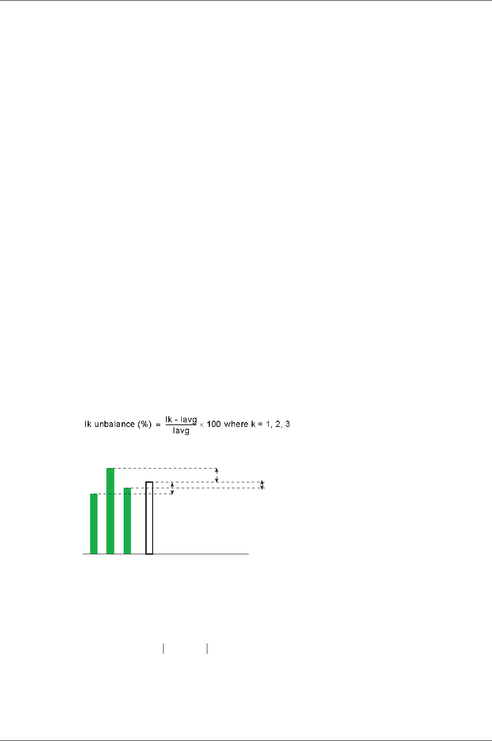
Measuring the Current and Voltage Phase Unbalances
Micrologic X control units calculate the current unbalance for each phase (3 values).
The current unbalance is a percentage of the average current:
Micrologic X control units calculate:
The phase-to-phase voltage unbalance for each phase (3 values)
The phase-to-neutral (if present) voltage unbalance for each phase (3 values)
The voltage unbalance is expressed as a percentage compared to the average value of the electrical
quantity (Vavg):
I1- Iavg I2 - Iavg I3 - Iavg
< 0 > 0 < 0
I1 I2 I3 Iavg
Vjk unbalance (%) Vjk - Vavg
Vavg
------------------------- 100 where jk = 12, 23, 31×=
Metering Functions
116 DOCA0102EN-00 05/2016
Maximum/Minimum Values
The Micrologic X control unit determines in real time the maximum (MAX) and minimum (MIN) value
reached by the following electrical quantities for the period from the last reset to the present time:
Current: phase and neutral currents, average currents and current unbalances
Voltage: phase-to-phase and phase-to-neutral voltages, average voltages, and voltage unbalances
Power: total power and phase power (active, reactive, and apparent)
Total harmonic distortion: the total harmonic distortion THD for both current and voltage
Frequency
The maximum value (MAXMAX) of all phase currents
The minimum value (MINMIN) of all phase currents
Resetting Maximum/Minimum Values
The maximum and minimum values can be reset:
On the Micrologic X display screen, at:
Home → Measures → Current
Home → Measures → Voltage
Home → Measures → Power
Home → Measures → Frequency
Home → Measures → I Harmonics
Home → Measures → V Harmonics
With Ecoreach software
With Masterpact MTZ mobile App
By sending a command using the communication network. This function is password-protected.
NOTE: The maximum and minimum power factors and cos Φ can be reset only:
With Ecoreach software
With Masterpact MTZ mobile App
By sending a command using the communication network. This function is password protected.
All maximum and minimum values for the group of electrical quantity selected are reset.
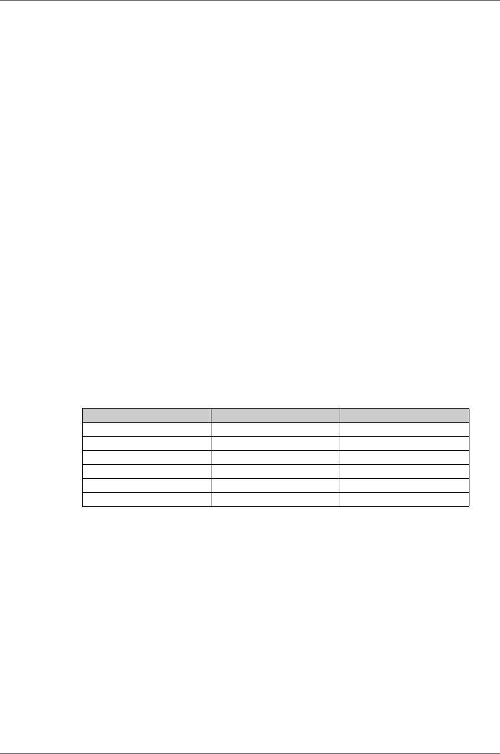
Resetting maximum and minimum generates a low severity event, which is logged in the Metering history,
as follows:
User message History Severity
Reset Min/Max currents Metering Low
Reset Min/Max voltages Metering Low
Reset Min/Max power Metering Low
Reset Min/Max frequency Metering Low
Reset Min/Max harmonics Metering Low
Reset Min/Max power factor Metering Low
Metering Functions
DOCA0102EN-00 05/2016 117
Power Metering
Presentation
The control unit calculates the electrical quantities required for power management:
The real-time values of the:
Active powers (total Ptot and per phase) in kW
Reactive powers (total Qtot and per phase) in kVAR
Apparent powers (total Stot and per phase) in kVA
The maximum and minimum values for each of these powers
The cos ϕ and power factor (PF) indicators
The operating quadrant and type of load (leading or lagging)
All these electrical quantities are continuously calculated and their value is updated once a second at rated
frequency.
Principle of Power Metering
The control unit calculates the power values from the current and voltage samples.
The calculation principle is based on:
Definition of the powers
Algorithms depending on the type of circuit breaker (4-pole or 3-pole)
Set value of the power sign (circuit breaker powered from the top or underside)
The calculation algorithm is explained in the specific topic
(see page 120)
.
Calculations use harmonics up to the fifteenth.
Total Power Calculation Method
The total reactive and apparent power can be calculated by one of the two following methods:
Vector
Arithmetic
NOTE: The total active power is calculated as a sum of the phase powers: Ptot = P1 + P2 + P3
The calculation method can be set in the following ways:
On the Micrologic X display screen, at Home → Configuration → Measures → Total P Calcul
With Ecoreach software
With Masterpact MTZ mobile App
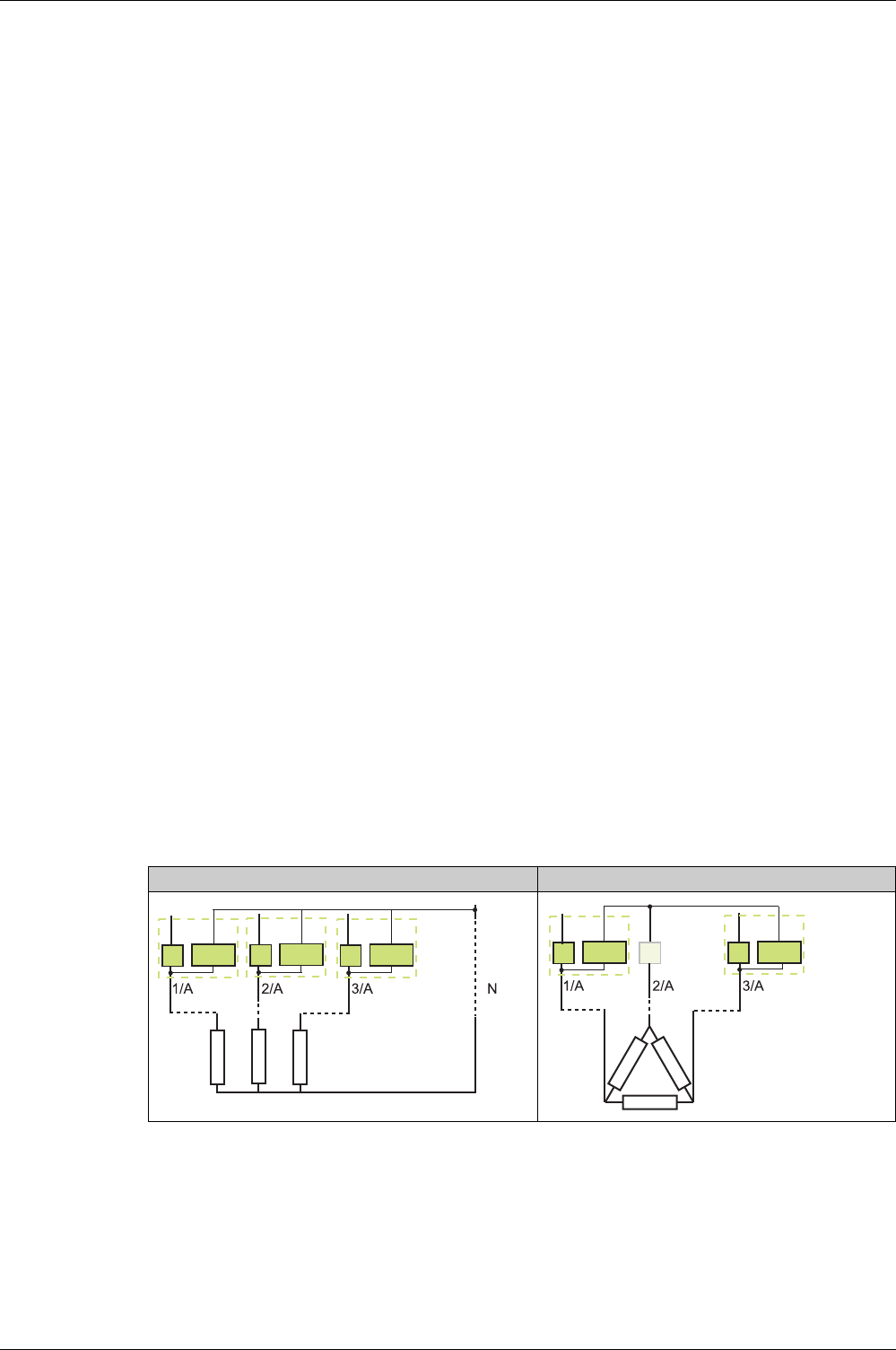
3-Pole Circuit Breaker, 4-Pole Circuit Breaker
The calculation algorithm depends on the presence or absence of voltage metering on the neutral
conductor.
4-pole or 3-pole with ENVT: 3-wattmeter method 3-pole without ENVT: 2-wattmeter method
I1 V1N I2 V2N I3 V3N
I1 U12 I2 I3 U32
W1 W2
Metering Functions
118 DOCA0102EN-00 05/2016
The following table lists the metering options:
3-Pole Circuit Breaker, Distributed Neutral
Declare the ENVT in the system type setting
(see page 114)
.
NOTE: Declaration of the ENVT alone does not result in correct calculation of the powers. It is essential to
connect the wire from the ENVT to the neutral conductor.
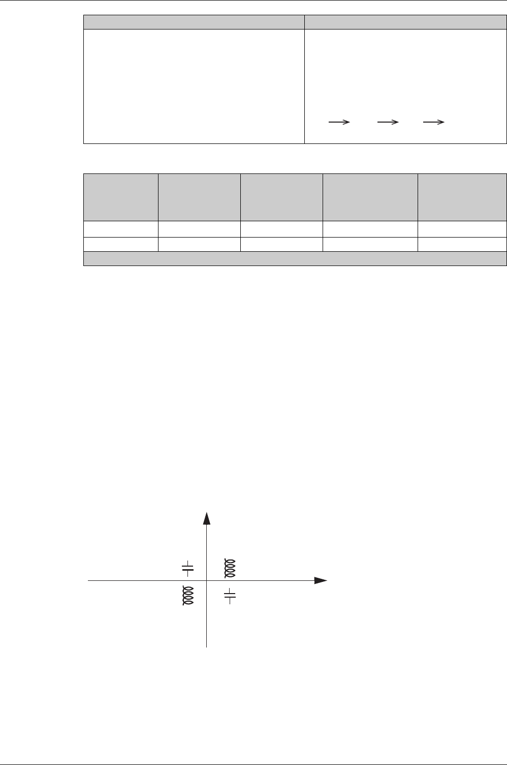
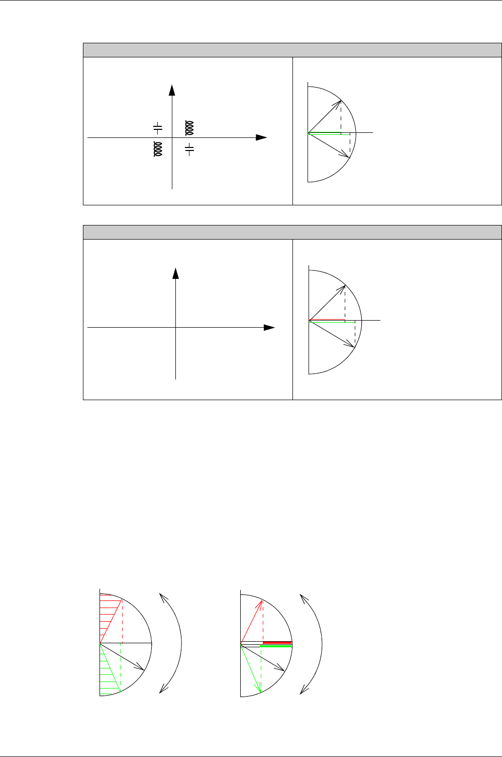
Power Sign and Operating Quadrant
By definition, the active powers are:
Signed + when they are consumed by the user, that is, when the device is acting as a receiver.
Signed - when they are supplied by the user, that is, when the device is acting as a generator.
By definition, the reactive powers have:
The same sign as the active energies and powers when the current lags behind the voltage, that is,
when the device is inductive (lagging).
The opposite sign to the active energies and powers when the current is ahead of the voltage, that is,
when the device is capacitive (leading).
These definitions therefore determine 4 operating quadrants (Q1, Q2, Q3, and Q4):
NOTE: The power values are:
Signed when read using the communication network.
Not signed when displayed on the Micrologic X display screen.
When there is voltage metering on the neutral (4-pole or 3-
pole circuit breaker with ENVT wired and configured), the
control unit measures the power by using 3 single-phase
loads downstream.
When there is no voltage metering on the neutral (3-
pole circuit breaker), the control unit measures the
power:
Using the current from 2 phases (I1 and I3) and
composite voltages from each of these 2 phases in
relation to the third (V12 and V23)
using the fact that by definition the current in the
neutral conductor is zero:
Method 3-pole circuit
breaker, non-
distributed neutral
3-pole circuit
breaker, distributed
neutral
3-pole circuit breaker,
distributed neutral
(ENVT wired and
configured)
4-pole circuit breaker
2 wattmeters X X 1––
3 wattmeters – – X X
1 The measurement is incorrect once there is current circulating in the neutral.
4-pole or 3-pole with ENVT: 3-wattmeter method 3-pole without ENVT: 2-wattmeter method
I1 +I2 + I3= 0
Lag
(Delay)
Lead
(Ahead)
Q2
Q3
P > 0 Q > 0P < 0
P > 0
Q > 0
0 < Q0 < QP < 0
Lead
(Ahead)
Lag
(Delay)
Q1
Q4
P
Q

Metering Functions
DOCA0102EN-00 05/2016 119
Power Sign Convention
The sign for the power running through the circuit breaker depends on the type of connection:
Circuit breakers with the active power flowing from upstream (top) to downstream (bottom) should be
set with the power sign P+
Circuit breakers with the active power flowing from downstream (bottom) to upstream (top) should be
set with the power sign P-
Set the power sign convention as follows:
On the Micrologic X display screen, on the screens Home → Configuration → Network → Power sign.
With Ecoreach software
With Masterpact MTZ mobile App
By sending a setting command using the communication network (password-protected)
Metering Functions
120 DOCA0102EN-00 05/2016
Power Calculation Algorithm
Presentation
The algorithms are given for both calculation methods (2 wattmeters and 3 wattmeters). The power
definitions and calculation are given for a network with harmonics.
With the 2-wattmeter calculation method, it is not possible to deliver power metering for each phase.
All the calculated quantities are displayed:
On the Micrologic X display screen, on the screens Home → Measures → Power
On the Ecoreach software
On the Masterpact MTZ mobile App
By a remote controller using the communication network
Active Powers
PW1 and PW2 are the fictitious powers calculated by the 2-wattmeter method.
Reactive Power
Apparent Power
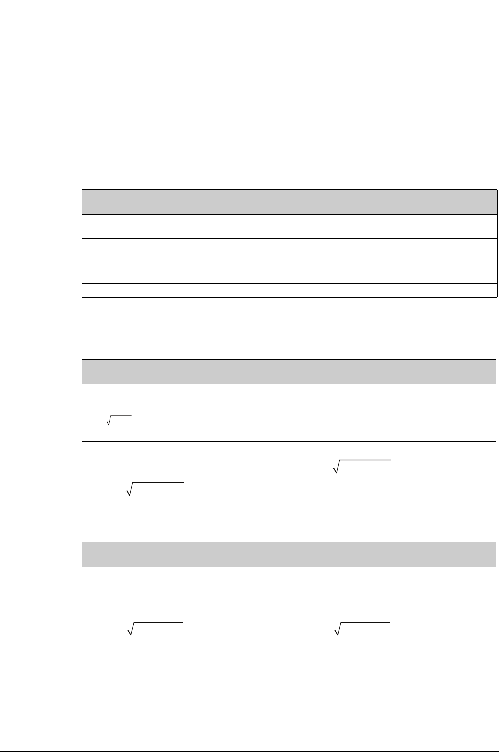
Metering on a 3-pole or 4-pole circuit breaker with ENVT
wired and configured
Metering on a 3-pole circuit breaker without ENVT wired
and configured
The active power for each phase and total active power is
calculated.
Only the total active power can be calculated.
–
Ptot = P1 + P2 + P3 Ptot = Pw1 + Pw2
1
T
T
Where p=1, 2, 3 (phase)
∫
=
Pp Vp(t)Ip(t)dt
Metering on a 3-pole or 4-pole circuit breaker with ENVT
wired and configured
Metering on a 3-pole circuit breaker without ENVT wired
and configured
The reactive power with harmonics for each phase and
total reactive power is calculated.
Only the total reactive power can be calculated.
–
With vector method:
Qtot V= Q1 + Q2 + Q3
With arithmetic method:
With arithmetic method:
Where i=1, 2, 3 (phase)
22
Qi PiSi±
=−
22
Stot Ptot
−
QtotA
=
22
Stot Ptot
−
QtotA
=
Metering on a 3-pole or 4-pole circuit breaker with ENVT
wired and configured
Metering on a 3-pole or 4-pole circuit breaker without
ENVT wired and configured
The apparent power for each phase and total apparent
power is calculated
Only the total apparent power can be calculated.
Sp = (Vp. Ip) where p = 1, 2, 3 (phase) –
With vector method:
With arithmetic method:
Stot A= S1 + S2 + S3
With vector method:
With arithmetic method:
StotA= S1 + S2 + S3
22
Ptot Qtot+
Stot
v
=
22
Ptot Qtot+
Stot
v
=
Metering Functions
DOCA0102EN-00 05/2016 121
Energy Metering
Presentation
The control unit calculates the different types of energy using energy meters and provides the values of:
The total active energy Ep, the active energy supplied EpOut, and the active energy consumed EpIn
The total reactive energy Eq, the reactive energy supplied EqOut, and the reactive energy consumed
EqIn
The total apparent energy Es
The energy values are calculated, and shown as an hourly consumption. Values update once a second at
rated frequency. Values are stored in non-volatile memory once an hour.
NOTE: To ensure reliable energy measurement across the current range the control unit must be powered
with an external 24 Vdc power supply or VPS module
(seepage23)
.
NOTE: The energies per phase are available as an option
(see page 129)
. They are calculated using the
same principles as total energies.
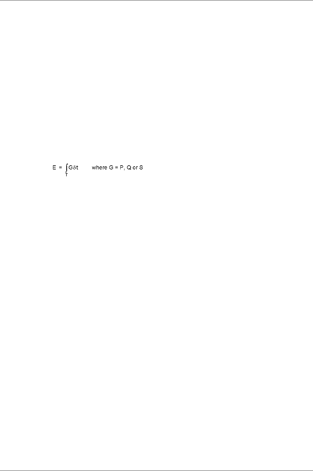
Principle of Energy Calculation
By definition energy is the integration of the real-time power over a period T. The integration period T is
equal to a number of cycles equal to the rated frequency.
Partial Energy Meters
For each type of energy, active or reactive, a partial consumed energy meter and a partial supplied energy
meter calculate the accumulated energy by incrementing once a second:
The contribution of the consumed power to the consumed energy meter
Ein(t)(consumed) = Ein(t - 1) + (Gin(t))/3600 where Gin = Ptot or Qtot consumed
The contribution as an absolute value of the supplied power for the supplied energy meter (supplied
power is always counted negatively)
Eout(t)(supplied) = Eout(t - 1) + (|Gout(t)|)/3600 where Gin = Ptot or Qtot supplied
For each partial energy meter two types of counter are available: one which can be reset and one which
cannot be reset.
Energy Meters
From the partial energy meters and for each type of energy, active or reactive, an energy meter provides
either of the following measurements once a second:
The absolute energy, by adding the consumed and supplied energies together. The energy
accumulation mode is absolute.
E(t)absolute = Ein(t) + Eout(t)
The signed energy, by differentiating between consumed and supplied energies. The energy
accumulation mode is signed.
E(t)signed = Ein(t) - Eout(t)
The apparent energy Es is always counted positively.
Selecting Energy Calculation
The information sought determines calculation selection:
The absolute value of the energy that has crossed the poles of a circuit breaker or the cables of an item
of electrical equipment is relevant for maintenance of an installation.
The signed values of the energy supplied and the energy consumed are required to calculate the
economic cost of an item of equipment.
By default, absolute energy accumulation mode is configured.
Select the energy calculation mode using any of the following methods:
On the Micrologic X display screen, on the screens Home → Configuration → Measures → E calcul
With Ecoreach software
With Masterpact MTZ mobile App
By or sending a setting command using the communication network.This function is password-
protected.

Metering Functions
122 DOCA0102EN-00 05/2016
Resetting Energy Meters
The energy meters can be reset:
On the Micrologic X display screen, on the screens Home → Measures → Energy → Reset Counter
With Ecoreach software
With Masterpact MTZ mobile App
By writing a reset command using the communication network. This function is password-protected.
All energy meters are reset together, except the 2 active energy accumulation meters (EpIn and EpOut)
that cannot be reset.
Resetting the energy meters generates a low severity event, which is logged in the Metering history.
Presetting Energy Meters
Metering Functions
DOCA0102EN-00 05/2016 123
Harmonic Currents and Voltages
Origin and Effects of Harmonics
Many nonlinear loads present on an electrical network create harmonic currents in the electrical network.
These harmonic currents:
Distort the current and voltage waves.
Degrade the quality of the distributed energy.
These distortions, if they are significant, can result in:
Malfunctions or degraded operation in the powered devices.
Unwanted heat rise in the devices and conductors.
Excessive power consumption.
These various problems increase the system installation and operating costs. It is therefore necessary to
control the energy quality carefully.
Definition of a Harmonic
A periodic signal is a superimposition of:
The original sinusoidal signal at the fundamental frequency (for example, 50 Hz or 60 Hz)
Sinusoidal signals whose frequencies are multiples of the fundamental frequency called harmonics
Any DC component
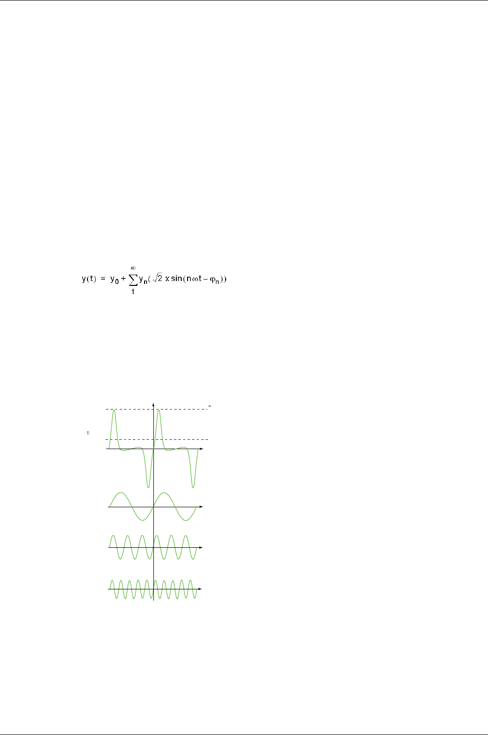
This periodic signal is broken down into a sum of terms:
where:
y0: value of the DC component
yn: rms value of the nth harmonic
ω: pulsation of the fundamental frequency
ϕn: phase displacement of harmonic component n
NOTE: The first harmonic is called the fundamental.
Example of a current wave distorted by a harmonic component:
1 Irms: rms value of the harmonic waveform
2 I1: fundamental current
3 I3: third order harmonic current
4 I5: fifth order harmonic current
H1 (50 Hz)
H3 (150 Hz)
H5 (250 Hz)
I
I
rms
I
t
t
t
t
1
2
3
4
Metering Functions
124 DOCA0102EN-00 05/2016
Power Quality Indicators
Presentation
The control unit calculates total harmonic distortion for voltages and currents.
Total harmonic distortions related to the fundamental value (THD(V), THD(I)) are displayed on the
Micrologic X display screen.
In addition, total harmonic distortions related to rms values (THD-R(V), and THD-R(I)) can be displayed
with Ecoreach software
Displaying the Total Harmonic Distortion
The total harmonic distortion THD can be displayed in the following ways:
On the Micrologic X display screen:
THD(I) at Home → Measures → I Harmonics
THD(V) at Home → Measures → V Harmonics
With Ecoreach software
On Masterpact MTZ mobile App
Through the communication network
Current THD
The current THD is a percentage of the rms value of harmonic currents of ranks greater than 1 in relation
to the rms value of the fundamental current (first order). The control unit calculates the total harmonic
current distortion THD up to the fifteenth harmonic:
The current THD can be higher than 100%.
Use the total harmonic distortion THD(I) to assess the distortion of the current wave with a single number.
The table below shows the THD limit values.
Distortion of the current wave created by a nonlinear device with a high THD(I) can lead to distortion of the
voltage wave, depending on the level of distortion and the source impedance. This distortion of the voltage
wave affects all of the devices powered by the supply. Sensitive devices on the system can therefore be
affected. A device with a high THD(I) may not be affected itself but could cause malfunctions on other,
more sensitive devices on the system.
NOTE: THD(I) metering is an effective way of determining the potential for problems from the devices on
electrical networks.
Voltage THD
The voltage THD is the percentage the rms value of harmonic voltages greater than 1 in relation to the rms
value of the fundamental voltage (first order). The control unit calculates the voltage THD up to the fifteenth
harmonic:
This factor can in theory be higher than 100% but is in practice rarely higher than 15%.
THD(I) Value Comments
THD(I) < 10% Low harmonic currents: little risk of malfunctions.
10% < THD(I) < 50% Significant harmonic currents: risk of heat rise, oversizing of supplies.
50% < THD(I) High harmonic currents: the risks of malfunction, degradation, and dangerous heat rise
are almost certain unless the installation is calculated and sized with this restriction in
mind.
15
100
I1rms
n = 2
Inrms
2
THD (I) =
∑
2
15
V1rms
n = 2
Vnrms
THD (V) =
∑
Metering Functions
DOCA0102EN-00 05/2016 125
Use the total harmonic distortion THD(V) to assess the distortion of the voltage wave with a single number.
The limit values below are commonly evaluated by energy distribution companies:
Distortion of the voltage wave affects all devices powered by the supply.
NOTE: Use the THD(V) indication to assess the risks of disturbance of sensitive devices supplied with
power.
Current THD-R
The current THD-R is a percentage of the rms value of harmonic currents of ranks greater than 1 in relation
to the total harmonic current. The control unit calculates the total harmonic current distortion THD-R up to
the fifteenth harmonic using the following equation:
The current THD-R cannot be higher than 100%.
Use the total harmonic distortion THD-R(I) to assess the distortion of the current wave with a single
number. The table below shows the THD-R limit values.
Distortion of the current wave created by a nonlinear device with a high THD-R(I) can lead to distortion of
the voltage wave, depending on the level of distortion and the source impedance. This distortion of the
voltage wave affects all of the devices powered by the supply. Sensitive devices on the system can
therefore be affected. A device with a high THD-R(I) may not be affected itself but could cause
malfunctions on other, more sensitive devices on the system.
NOTE: THD-R(I) metering is an effective way of determining the potential for problems from the devices
on electrical networks.
Voltage THD-R
The voltage THD-R is the percentage the rms value of harmonic voltages greater than 1 in relation to the
total harmonic voltage. The control unit calculates the total harmonic voltage distortion THD-R up to the
fifteenth harmonic.
Use the total harmonic distortion THD-R(V) to assess the distortion of the voltage wave with a single
number. The limit values below are commonly evaluated by energy distribution companies:
Distortion of the voltage wave affects all devices powered by the supply.
NOTE: Use the THD-R(V) indication to assess the risks of disturbance of sensitive devices supplied with
power.
THD(V) Value Comments
THD(V) < 5% Insignificant distortion of the voltage wave: little risk of malfunctions.
5% < THD(V) < 8% Significant distortion of the voltage wave: risk of heat rise and malfunctions.
8% < THD(V) Significant distortion of the voltage wave: there is a high risk of malfunction unless the
installation is calculated and sized based on this distortion.
THD-R(I) Value Comments
THD-R(I) < 10% Low harmonic currents: little risk of malfunctions.
10% < THD-R(I) < 50% Significant harmonic currents: risk of heat rise, oversizing of supplies.
50% < THD-R(I) High harmonic currents: the risks of malfunction, degradation, and dangerous heat rise
are almost certain unless the installation is calculated and sized with this restriction in
mind.
THD-R(V) Value Comments
THD-R(V) < 5% Insignificant distortion of the voltage wave: little risk of malfunctions.
5% < THD-R(V) < 8% Significant distortion of the voltage wave: risk of heat rise and malfunctions.
8% < THD-R(V) Significant distortion of the voltage wave: there is a high risk of malfunction unless the
installation is calculated and sized based on this distortion.
Metering Functions
126 DOCA0102EN-00 05/2016
Power Factor PF and cos ϕ Measurement
Power Factor PF
The control unit calculates:
The power factor per phase PF1, PF2, PF3, from the phase active and apparent powers
The total power factor PF from the total active power Ptot and the total apparent power Stot
NOTE: Stot is the vector or arithmetic total apparent power, depending on the setting
(see page 120)
.
This indicator qualifies:
The oversizing necessary for the installation power supply when harmonic currents are present
The presence of harmonic currents by comparison with the value of the cos ϕ (see below)
cos ϕ
The control unit calculates:
The cos ϕ per phase from the phase active and apparent powers of the fundamental
the cos ϕ from the total active power Pfundtot and the total apparent power Sfundtot of the fundamental
(first order)
This indicator qualifies use of the energy supplied.
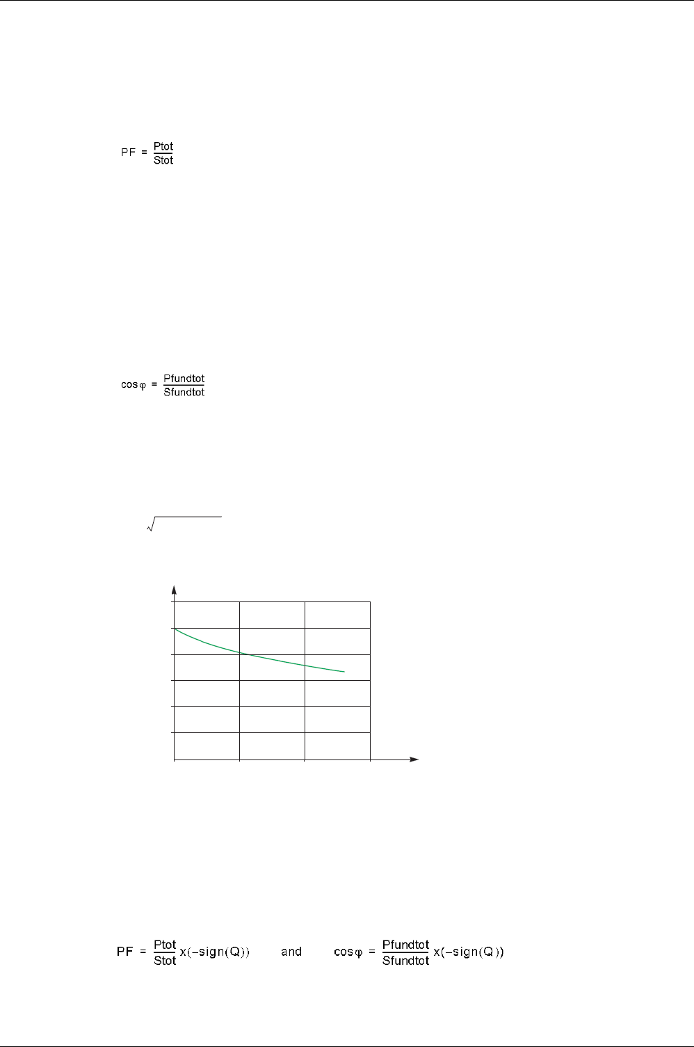
Power Factor PF and cos ϕ when Harmonic Currents are Present
If the supply voltage is not too distorted, the power factor PF is expressed as a function of the cos ϕ and
the THD(I) by:
The graph below specifies the value of PF/cos ϕ as a function of the THD(I):
By comparing the 2 values, it is possible to estimate the level of harmonic deformation on the supply.
Sign for the Power Factor PF and cos ϕ
2 sign conventions can be applied for these indicators:
IEC convention: The sign for these indicators complies strictly with the signed calculations of the powers
(that is, Ptot, Stot, Pfundtot, and Sfundtot).
IEEE convention: The indicators are calculated in accordance with the IEC convention but multiplied by
the inverse of the sign for the reactive power (Q).
PF cos ϕ
1THDI()
2
+
------------------------------------
≈
1.2
0.8
1
0.6
0.4
0.2
0 50 100 150
FP/cos J
THD(I) %
Metering Functions
DOCA0102EN-00 05/2016 127
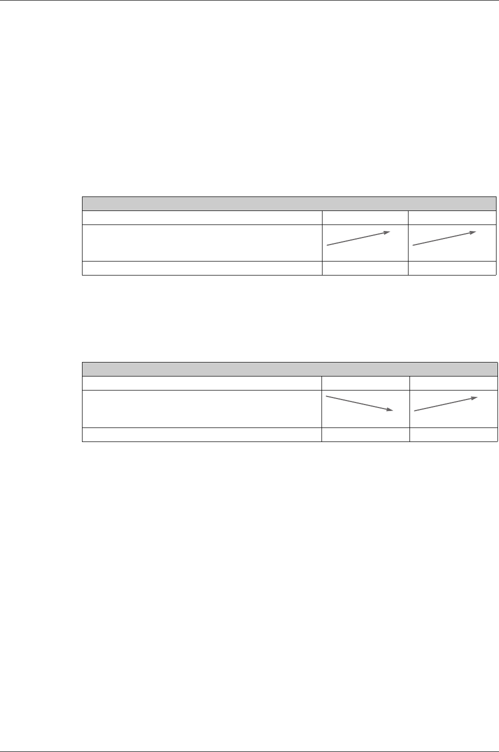
The figures below define the sign for the power factor PF and cos ϕ by quadrant (Q1, Q2, Q3 and Q4) for
both conventions:
NOTE: For a device, a part of an installation which is only a receiver (or generator), the advantage of the
IEEE convention is that it adds the type of reactive component to the PF and cos ϕ indicators:
Lead: positive sign for the PF and cos ϕ indicators
Lag: negative sign for the PF and cos ϕ indicators
Managing the Power Factor PF and cos ϕ: Minimum and Maximum Values
Managing the PF and cos ϕ indicators consists of:
Defining critical situations
Implementing monitoring of the indicators in accordance with the definition of critical situations
Situations are considered critical when the values of the indicators are around 0. The minimum and
maximum values of the indicators are defined for these situations.
The figure below illustrates the variations of the cos ϕ indicator (with the definition of the cos ϕ MIN/MAX)
and its value according to IEEE convention for a receiver application:
1 Arrows indicating the cos ϕ variation range for the load in operation
2 Critical zone + 0 for highly capacitive devices (shaded green)
IEC Convention
Operation in all quadrants (Q1, Q2, Q3, Q4) Values of cos ϕ in receiver operation (Q1, Q4)
IEEE Convention
Operation in all quadrants (Q1, Q2, Q3, Q4) Values of cos ϕ in receiver operation (Q1, Q4)
Q2
4Q
P > 0 Q > 0 PF >0P < 0
P > 0
Q > 0
0<Q0<QP < 0 PF >0
PF <0
PF <0
Inductive
Capacitive
Capacitive
Q
P
1Q
Q3
Inductive
0 +
-1
+1
0 +
Q4
Q1
cos J>0
cos J>0
P > 0 Q > 0
PF >0
P < 0
P > 0
Q > 0
0 < Q0 < QP < 0
PF >0PF <0
PF <0
Q2
Lagging
Leading
Leading
Lagging
Q
P
Q1
4Q3Q
0 -
-1
+1
0 +
Q4
Q1
cos J<0
cos J>0
-1
+1
cos J
MIN cos J
MAX cos J
- 0
+ 0
-1
+1
cos J
+ 0
1
2
3
1
4
5
6
7
- 0
Q4
Q1
Q4
Q1
Metering Functions
128 DOCA0102EN-00 05/2016
3 Critical zone - 0 for highly inductive devices (shaded red)
4 Minimum position of the load cos ϕ (lagging): red arrow
5 Variation range of the value of the load cos ϕ (lagging): red
6 Maximum position of the load cos ϕ (leading): green arrow
7 Variation range of the value of the load cos ϕ (leading): green
PF MAX (or cos ϕ MAX) is obtained for the smallest positive value of the PF (or cos ϕ) indicator.
PF MIN (or cos ϕ MIN) is obtained for the largest negative value of the PF (or cos ϕ) indicator.
NOTE: The minimum and maximum values of the PF and cos ϕ indicators are not physically significant:
they are markers which determine the ideal operating zone for the load.
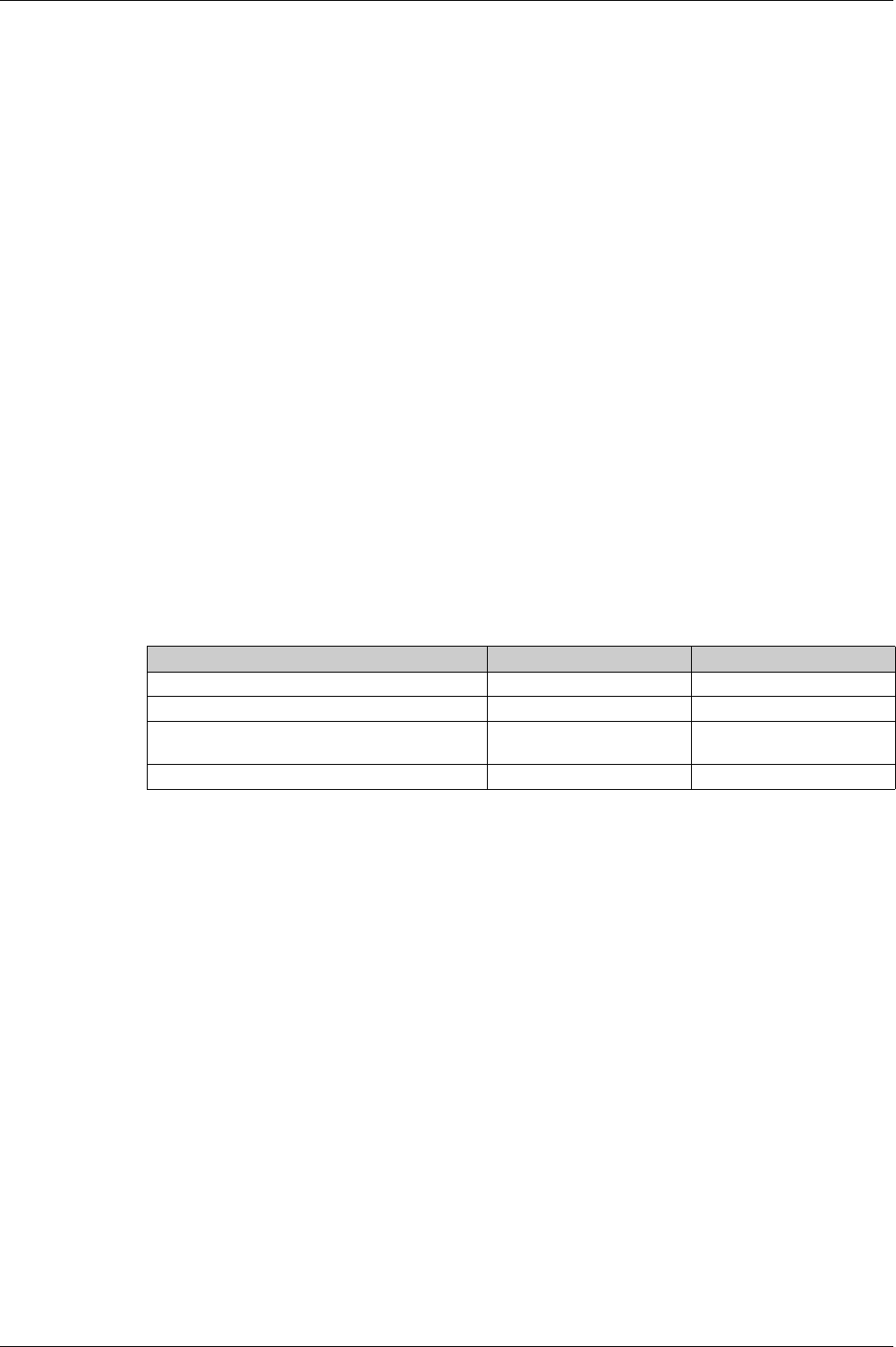
Monitoring the cos ϕ and Power Factor PF Indicators
According to the IEEE convention, critical situations in receiver mode on a capacitive or inductive load are
detected and discriminated (2 values).
The table below indicates the direction in which the indicators vary and their value in receiver mode.
The quality indicator MAX and MIN indicate both critical situations.
According to the IEC convention, critical situations in receiver mode on a capacitive or inductive load are
detected but not discriminated (one value).
The table below indicates the direction in which the indicators vary and their value in receiver mode.
The quality indicator MAX indicates both critical situations.
Selecting the Sign Convention for the cos ϕ and Power Factor PF
Set the sign convention for the cos ϕ and PF indicators as follows:
With Ecoreach software
With Masterpact MTZ mobile App
By sending a setting command using the communication network.This function is password-protected.
The IEEE convention is applied by default.
The selection is displayed on the Micrologic X display screen, at Home → Configuration → Measures →
PF/VAR Conv.
IEEE Convention
Operating quadrant Q1 Q4
Direction in which the cos ϕ (or PFs) vary over the operating range
Value of the cos ϕ (or PFs) over the operating range 0...-0.3...-0.8...-1 +1...+0.8...+0.4...0
IEC Convention
Operating quadrant Q1 Q4
Direction in which the cos ϕ (or PFs) vary over the operating range
Value of the cos ϕ (or PFs) over the operating range 0...+0.3...+0.8...+1 +1...+0.8...+0.4...0
MIN MAX
MIN MAX
MAX MIN
MIN MAX

Metering Functions
DOCA0102EN-00 05/2016 129
Optional Meter ing Functions
Section 4.2
Optional Metering Functions
Energy per Phase
Presentation
The Energy per Phase Digital Module enables the analysis of energy consumption per phase. It is
especially recommended for low voltage installations having a large amount of unbalanced loads. At the
point of measurement, it allows the calculation of and displays the consumed and supplied energy on each
phase of the network. It calculates and displays active, reactive and apparent energy per phase.
The energy per phase is calculated using the method described for calculating energy
(see page 121)
.
Prerequisites
The Energy per Phase Digital Module is an optional Digital Module, which can be purchased and installed
on a Micrologic X control unit
(see page 20)
.
The prerequsites are:
The Masterpact MTZ mobile App must be installed on a smartphone
The smartphone must be connected to the Micrologic X control unit through:
Bluetooth: the control unit must be powered
NFC: the control unit does not need to be powered
The Micrologic X date and time must be up to date
Measurement Availability
The measurements can be consulted in the following ways:
With Masterpact MTZ mobile App
With Ecoreach software
By sending a command using the communication network
Metering Functions
130 DOCA0102EN-00 05/2016
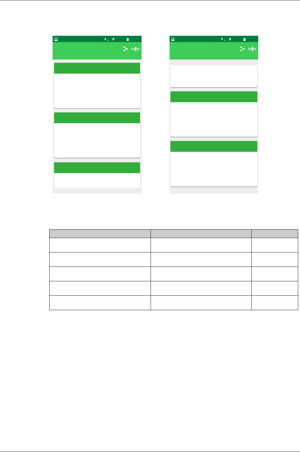
Examples of Screens in the Masterpact MTZ mobile App
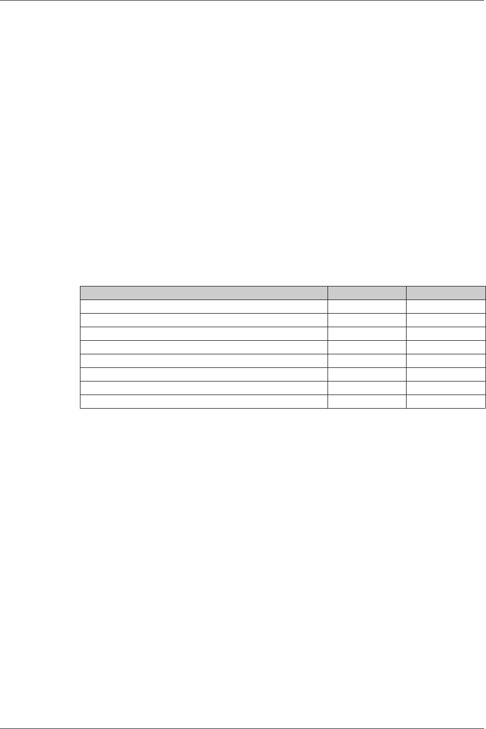
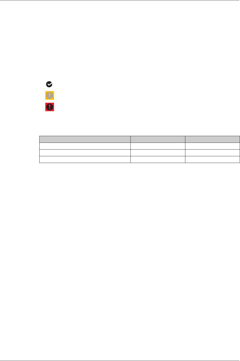
The following table shows examples of screens from the Masterpact MTZ mobile App:
Characteristics
Resetting Energy Per Phase
Energy per phase can be reset and preset as other energy measurements
(see page 122)
.
ÅEnergy Per Pha...
MTZ2 10 MAIN
Phase A
Active Received 4000 kWh
Active Delivered 4001 kWh
Reactive Received 4002 kVArh
Reactive Delivered 4003 kVArh
Apparent 4004 kVAh
Phase B
Active Received 5000 kWh
Active Delivered 5001 kWh
Reactive Received 5002 kVArh
Reactive Delivered 5003 kVArh
Apparent 5004 kVAh
Phase C
Active Received 6000 kWh
Active Delivered 6001 kWh
75% 13:52N
ÅEnergy Per Pha...
MTZ2 10 MAIN
Reactive Received 4002 kVArh
Reactive Delivered 4003 kVArh
Apparent 4004 kVAh
Phase B
Active Received 5000 kWh
Active Delivered 5001 kWh
Active Delivered 4001 kWh
Reactive Received 5002 kVArh
Reactive Delivered 5003 kVArh
Apparent 5004 kVAh
Phase C
Active Received 6000 kWh
Active Delivered 6001 kWh
Reactive Received 6002 kVArh
Reactive Delivered 6003 kVArh
Apparent 6004 kVAh
75% 13:52N
Measurement Range Accuracy range
Active energy IN per phase -10,000,000–10,000,000
kWh
+/-1 %
Active energy OUT per phase -10,000,000–10,000,000
kWh
+/-1 %
Reactive energy IN per phase -10,000,000–10,000,000
kVARh
+/-1 %
Reactive energy OUT per phase -10,000,000–10,000,000
kVARh
+/-1 %
Apparent energy per phase 0–10,000,000
kVARh
+/-1 %

DOCA0102EN-00 05/2016 131
Micrologic X
Diagnosti c and Maint enance Fu nctions
DOCA0 102EN-00 05/2016
Diagnostic an d Mainten ance Functions
Chapter 5
Diagnostic and Maintenance Functions
What Is in This Chapter?
This chapter contains the following sections:
Section Topic Page
5.1 Maintenance Assistance 132
5.2 Standard Diagnostic Functions 135
5.3 Optional Diagnostic Functions 144


Diagnostic and Maintenance Functions
DOCA0102EN-00 05/2016 133
Maintenance Schedule
Presentation
The maintenance schedule function records the date of the last maintenance operation.
Operating Principle
The date of the last maintenance operation is either recorded automatically after a secondary injection test
or configured manually.
Function Settings
Manual configuration can be made in the following ways:
With Ecoreach software
By sending a setting command using the communication network

Diagnostic and Maintenance Functions
134 DOCA0102EN-00 05/2016
Circuit Breaker Overview
Presentation
The overview function displays a description of the circuit breaker, including:
Name
Rating
Performance
Number of poles
Function Output
The information is available as follows:
On the Micrologic X display screen at Home → Maintenance → CB overview
With Ecoreach software
With Masterpact MTZ mobile App
On a remote controller using the communication network

Diagnostic and Maintenance Functions
DOCA0102EN-00 05/2016 135
Standard Di agnostic Fu nctions
Section 5.2
Standard Diagnostic Functions
What Is in This Section?
This section contains the following topics:
Topic Page
Health Monitoring 136
Circuit Breaker Monitoring 137
Monitoring the Tripping Function 138
Monitoring the Opening/Closing Function 139
Monitoring the Contact State 140
Monitoring the Internal Functioning of the Micrologic X control unit 141
Monitoring the ULP Modules 142
Monitoring the Circuit Breaker Service Life 143

Diagnostic and Maintenance Functions
136 DOCA0102EN-00 05/2016
Health Monitoring
Presentation
The health of the Micrologic X control unit is assessed by an internal analysis of the following indicators:
Circuit breaker monitoring state
Contact state
(see page 140)
Circuit breaker lifespan
(see page 143)
Health is presented with one of the following icons:
OK if no high- or medium-level event is detected
Orange icon if at least one medium-level event is detected
Red icon if at least one high-level event is detected
NOTE: Quick View on the Micrologic X display screen displays health with the OK icon when no event
is detected. When an event is detected a pop-up screen is displayed
(see page 169)
.
Function Outputs
Details about health can be accessed:
With Ecoreach software
With Masterpact MTZ mobile App through Bluetooth
On a remote controller using the communication network

Diagnostic and Maintenance Functions
DOCA0102EN-00 05/2016 137
Circuit Breaker Monitoring
Presentation
The Micrologic X control unit assesses the health of the circuit breaker by an internal monitoring of the
following functions:
Tripping function
Closing and opening function
Earth-leakage function (for Micrologic 7.0 X)
Control unit state
Circuit Breaker Monitoring Outputs
The circuit breaker monitoring state is presented with one of the following icons:
if no high- or medium-level event is detected
if at least one medium-level event is detected
if at least one high-level event is detected
The circuit breaker monitoring state is displayed:
On Ecoreach software
On Masterpact MTZ mobile App through Bluetooth
On a remote controller using the communication network
Diagnostic and Maintenance Functions
138 DOCA0102EN-00 05/2016
Monitoring the Tripping Function
Presentation
The Micrologic X control unit provides constant monitoring of the internal circuit of the circuit breaker, from
the current sensors to the tripping actuator (Mitop).
Operating Principle
The result of the monitoring is indicated by the ready LED on the front face of the Micrologic X control unit,
as follows:
The ready LED is flashing
The circuit breaker is closed and the internal current is greater than 50 A (if the Micrologic X control
unit is not powered by an auxiliary source)
The internal circuit of the circuit breaker is functioning correctly
The ready LED is off: a malfunction detected in the internal circuit
Tripping Data
The following data about the tripping function is logged by the Micrologic X control unit:
Total number of trips
The name and date of the last test trip
The tripping data is displayed:
With Ecoreach software
With the Masterpact MTZ mobile App through Bluetooth
With the Masterpact MTZ mobile App through NFC
On a remote controller using the communication network
Predefined Events
The function generates the following events:
Event message History Severity
Micrologic self-test major malfunction Diagnostic High
Internal current sensors (CT) disconnected Diagnostic High
External neutral current sensor (ENCT)
disconnected
Diagnostic High
Earth leakage (Vigi) sensor disconnected Diagnostic High
Diagnostic and Maintenance Functions
DOCA0102EN-00 05/2016 139
Monitoring the Opening/Closing Function
Presentation
The Micrologic X control unit monitors communicating voltage releases.
It also counts the number of charging sequences performed by the MCH gear motor.
Monitoring the Communicating Voltage Releases
The function monitors the presence and functioning of the following:
The communicating MN undervoltage release
The communicating MX opening voltage release
The communicating XF closing voltage release
Events are generated for a detected malfunction or when the presence of a communicating voltage release
is no longer detected.
Counting MCH Gear Motor Charging Sequences
The Micrologic X control unit counts the number of charging sequences performed by the MCH gear motor
to rearm the closing mechanism after each circuit breaker closure.
Events are generated when the number reaches 80% and 100% of the maximum.
Predefined Events
The function generates the following events:
Event History Severity
MX1 opening release malfunction Diagnostic Medium
MX1 opening release is no longer detected. Diagnostic Medium
MX2/MN opening release malfunction Diagnostic Medium
MX2/MN opening release is no longer detected. Diagnostic Medium
XF closing release malfunction Diagnostic Medium
XF closing release is no longer detected. Diagnostic Medium
MCH has reached 80% of the maximum number of operations Diagnostic Medium
MCH has reached the maximum number of operations Diagnostic High
Diagnostic and Maintenance Functions
140 DOCA0102EN-00 05/2016
Monitoring the Contact State
Presentation
The pole contacts undergo wear due to the number of operating cycles with current and interrupted current
during short circuits. It is recommended to check them at periodic intervals to decide whether the contacts
must be changed or not. To avoid regular inspection of the contacts and the arc chute, the contact wear
estimate helps with the planning of visual inspections based on the estimated wear (from 0% - new contact
- to 100% - totally worn contact).
The contact wear increases every time the circuit breaker interrupts or establishes the circuit with current.
Function Outputs
The function displays the contact wear on Ecoreach and Masterpact MTZ mobile App:
OK if wear < 60%
Medium level alarm if wear > 60% or > 95%
High-level alarm if wear > 99%
Predefined Events
The function generates the following events:
User message History Severity
Contact 60% worn out Diagnostic Medium
Contact 95% worn out Diagnostic Medium
Contact 100% worn out Diagnostic High

Diagnostic and Maintenance Functions
DOCA0102EN-00 05/2016 141
Monitoring the Internal Functioning of the Micrologic X control unit
Presentation
The Micrologic X control unit carries out a series of autotests to monitor:
Correct internal functioning
The state of the internal battery for power for power supply to trip-cause LEDs and red service LED
The external sensors (ENCT)
Wireless communication
Operating Principle
The ready LED and fault-trip indication LEDs provide visual information on the health of the Micrologic X
control unit. Detected malfunctions can be classified as high or medium severity events:
Medium severity event indicating minor malfunction detected
All fault-trip LEDs are lit
The ready LED is flashing
An orange pop-up screen is displayed
Current (LSI G/V) protection unaffected
High severity event indicating major malfunction detected:
All fault-trip LEDs are lit
The ready LED is off
A red pop-up screen is displayed
Current (LSI G/V) protection can be affected
Control unit must be replaced
An event is generated each time a malfunction is detected.
Predefined Events
The function generates the following events:
User message History Severity
Current protection reset to default settings Diagnostic High
Reading accessing protection settings error Diagnostic Medium
Product self-test minor malfunction Diagnostic Medium
Metering and advanced protection malfunction Diagnostic Medium
Display screen or wireless malfunction Diagnostic Medium
Replace battery Diagnostic Medium
Minor- Corrected ASIC internal error warning Diagnostic Medium
FW internal error Diagnostic Medium
Sensor plug reading error Diagnostic High
Discrepancy ASIC configuration Diagnostic High
Critical hardware module discrepancy Diagnostic Medium
Critical firmware module discrepancy Diagnostic Medium
Non-critical hardware module discrepancy Diagnostic Medium
Non-critical firmware module discrepancy Diagnostic Medium
ULP module address conflict Diagnostic Medium
Firmware discrepancy within product Diagnostic Medium
NFC malfunction Diagnostic Medium
Bluetooth malfunction Diagnostic Medium
IEEE 802.15.4 malfunction Diagnostic Medium

Diagnostic and Maintenance Functions
142 DOCA0102EN-00 05/2016
Monitoring the ULP Modules
Presentation
The Micrologic X control unit monitors the connection and compatibility of settings of the following ULP
modules:
IO modules
IFE Ethernet Interface
Predefined Events
The function generates the following events:
User message History Severity
IO1 module connection lost Diagnostic Medium
IO2 module connection lost Diagnostic Medium
IFE connection lost Diagnostic Medium
Conflict with IO module configuration Configuration Medium
ULP module address conflict Diagnostic Medium
Diagnostic and Maintenance Functions
DOCA0102EN-00 05/2016 143
Monitoring the Circuit Breaker Service Life
Presentation
Circuit breaker service life depends on the daily number of operating cycles with or without current. The
maximum service life depends on the number of operating cycles indicated in the catalog under
mechanical and electrical durability. The service life indicator helps anticipate the replacement of the
breaking block before mechanical or electrical breakdown.
Operating Principle
Each time the circuit breaker operates (performs an open and close cycle with or without current), the
corresponding mechanical or electrical operating counter is incremented. The Micrologic X control unit
calculates the number of cycles performed as a percentage of the maximum number of operations. The
percentage of lifetime remaining for the device is calculated.
Function Outputs
The circuit breaker service life is presented as one of the following:
OK if remaining life > 20%
Medium level alarm if remaining life < 20%
High-level alarm if remaining life = 0%
It is displayed in the following ways:
With Ecoreach software
With Masterpact MTZ mobile App through Bluetooth
On a remote controller using the communication network
Predefined Events
The function generates the following events:
User message History Severity
Circuit breaker operations has passed 80% of
service life
Diagnostic Medium
Circuit breaker operations has passed the service life Diagnostic High

Diagnostic and Maintenance Functions
144 DOCA0102EN-00 05/2016
Optional D iagnostic Fu nctions
Section 5.3
Optional Diagnostic Functions
What Is in This Section?
This section contains the following topics:
Topic Page
Power Restoration Assistant Digital Module 145
Masterpact Operation Assistant Digital Module 146
Waveform Capture on Trip Event Digital Module 147
Diagnostic and Maintenance Functions
DOCA0102EN-00 05/2016 145
Power Restoration Assistant Digital Module
Presentation
The Power Restoration Digital Module helps to reduce the time without a power supply for critical load
(mean time to recovery (MTTR)) after a trip, an opening, or a loss of upstream supply.
The Digital Module provides the following assistance to help in the decision to restore power:
Displays information on events and circuit breaker status
Assists in determining the cause of events
Prerequisites
The Power Restoration Digital Module is an optional Digital Module, which can be purchased and installed
on a Micrologic X control unit
(see page 20)
.
The prerequsites are:
The Masterpact MTZ mobile App must be installed on a smartphone
The smartphone must be connected to the Micrologic X control unit through:
Bluetooth: the control unit must be powered
NFC: the control unit does not need to be powered
The Micrologic X date and time must be up to date
Availability of Assistance
Availability of features differs depending on the type of connection to the Digital Module:
Through Bluetooth
Through NFC (connection can be made when control unit is not powered)
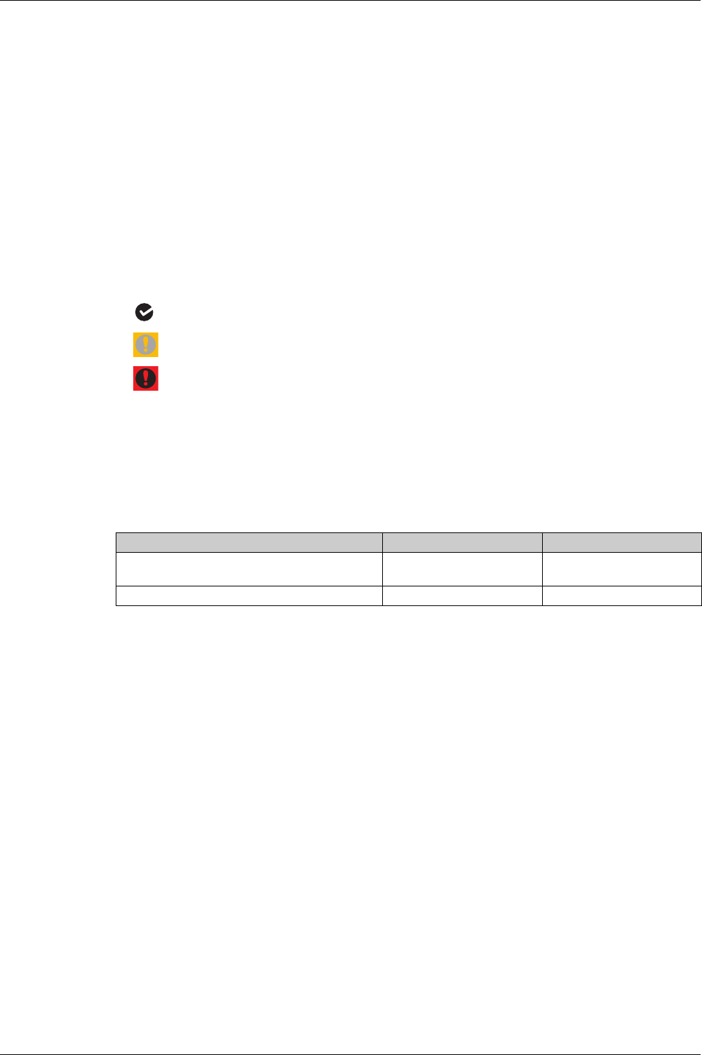
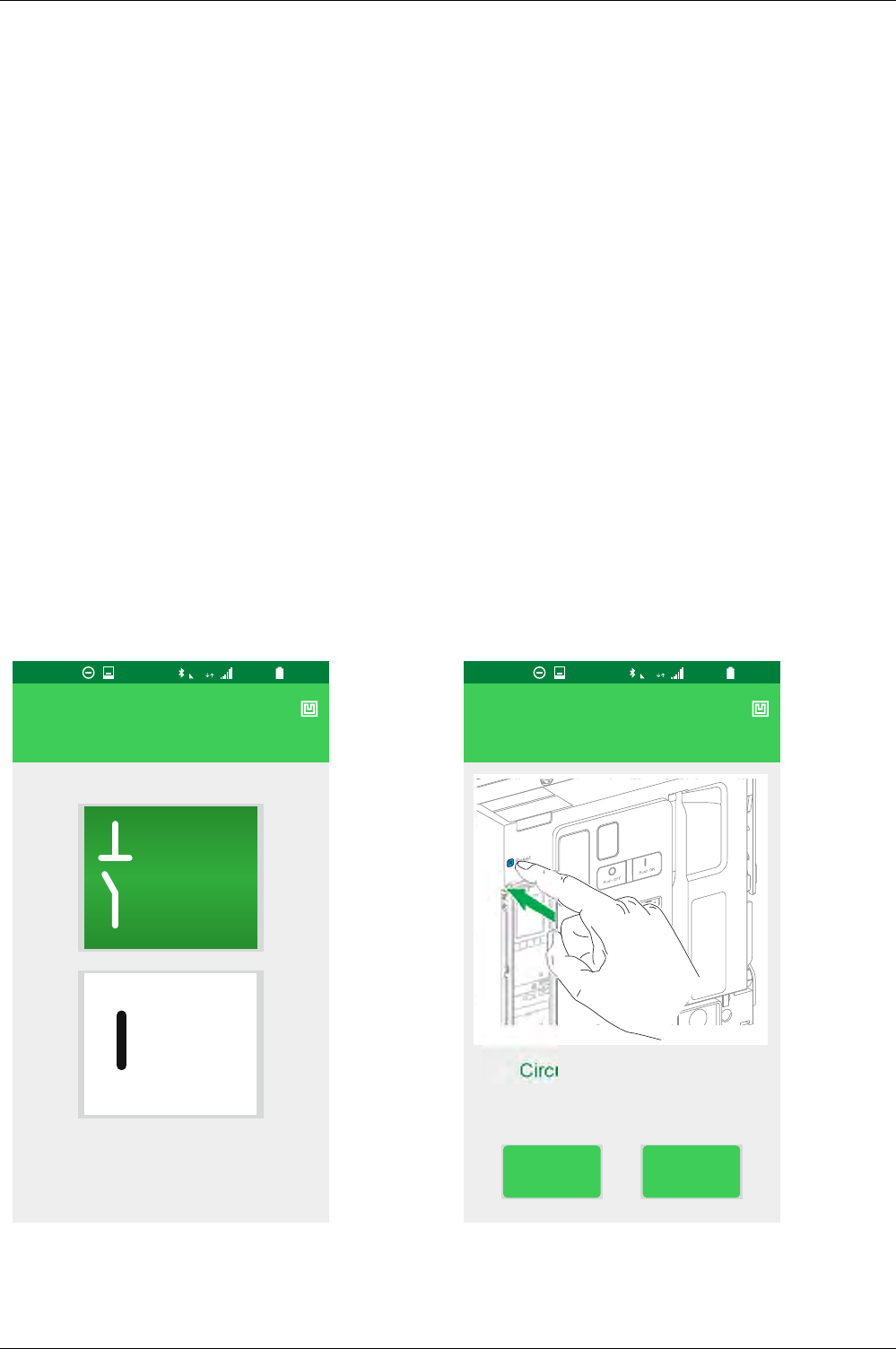
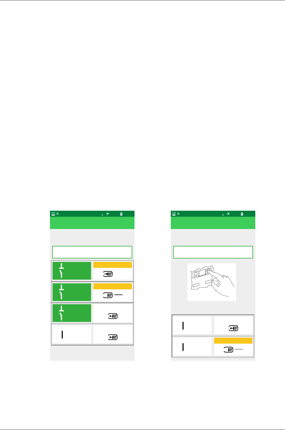
Examples of Screens
Some examples of the screens available on the Digital Module are provided:
Orange F
ÅHelp to restore power
Check circuit breaker state
None of these states
MTZ2 10 MAIN
100% 13:25
4G
ON
0OFF
N
Orange F
ÅCheck Trip
Circuit breaker is tripped
Check mechanical indicator
if in or out
MTZ2 10 MAIN
100% 13:25
4G
OUT IN
N
Pull
Diagnostic and Maintenance Functions
146 DOCA0102EN-00 05/2016
Masterpact Operation Assistant Digital Module
Presentation
The Masterpact Operation Assistant Digital Module helps to close the circuit breaker after a trip or opening.
The following features are available:
Ready-to-close status
Reset (if applicable)
Spring charging (if applicable)
Diagnostics on related reclosing information, for example, no power supply to MX, MN, or MCH
Prerequisites
The Masterpact Operation Assistant Digital Module is an optional Digital Module, which can be purchased
and installed on a Micrologic X control unit
(see page 20)
.
The prerequsites are:
The Masterpact MTZ mobile App must be installed on a smartphone
The smartphone must be connected to the Micrologic X control unit through:
Bluetooth: the control unit must be powered
NFC: the control unit does not need to be powered
The Micrologic X date and time must be up to date
Availability of Assistance
Availability of features differs depending on the type of connection to the Digital Module:
Through Bluetooth: all features are available
Through NFC (connection can be made when control unit is not powered): ???
Examples of Screens
ÅHelp to close circuit breaker
Check Circuit breaker state
Step 01
81% 12:13
ON
0OFF
0OFF
Please check the actual state of the breaker
click on the corresponding illustration
DISCHARGED
DISCHARGED
OK
CHARGED
0OFF
OK
CHARGED
N
ÅHelp to close circuit breaker
Closing Breaker
Step 02
81% 12:13
Locally (Mechanical):
Select the new state of the Circuit Breaker
Press the mechanical ON Push Button
ON
DISCHARGED
ON
OK
CHARGED
N

Diagnostic and Maintenance Functions
DOCA0102EN-00 05/2016 147
Waveform Capture on Trip Event Digital Module
Presentation
The Waveform Capture on Trip Event Digital Module allows five cycles of phase and neutral currents to be
logged after a trip on LSI or G protection, with a sampling period of 512 ms. One cycle before and four after
the trip are logged.
In addition, the waveform capture function records the digital status of the following:
Circuit breaker trip orders
ZSI-IN signal
SDE
Open position of circuit breaker
One waveform capture is available at any one time. Generating a new waveform capture replaces the
previous one.
At delivery no waveform capture is available. A waveform capture is only available after the device has
tripped due to overcurrent or ground-fault protection. Trips due to tests run in Ecoreach software are not
recorded.
Prerequisites
The Waveform Capture on Trip Event Digital Module is an optional Digital Module, which can be purchased
and installed on a Micrologic X control unit
(see page 20)
.
The prerequsites are:
The Masterpact MTZ mobile App must be installed on a smartphone
The smartphone must be connected to the Micrologic X control unit through Bluetooth:
The Micrologic X date and time must be up to date
Availability of Data
The waveform capture is displayed in the following ways:
On the Masterpact MTZ mobile App from the Logs menu
In Ecoreach software
As a COMTRADE file exported through the Masterpact MTZ mobile App or Ecoreach software, for use
with Schneider Electric Wavewin-SE software
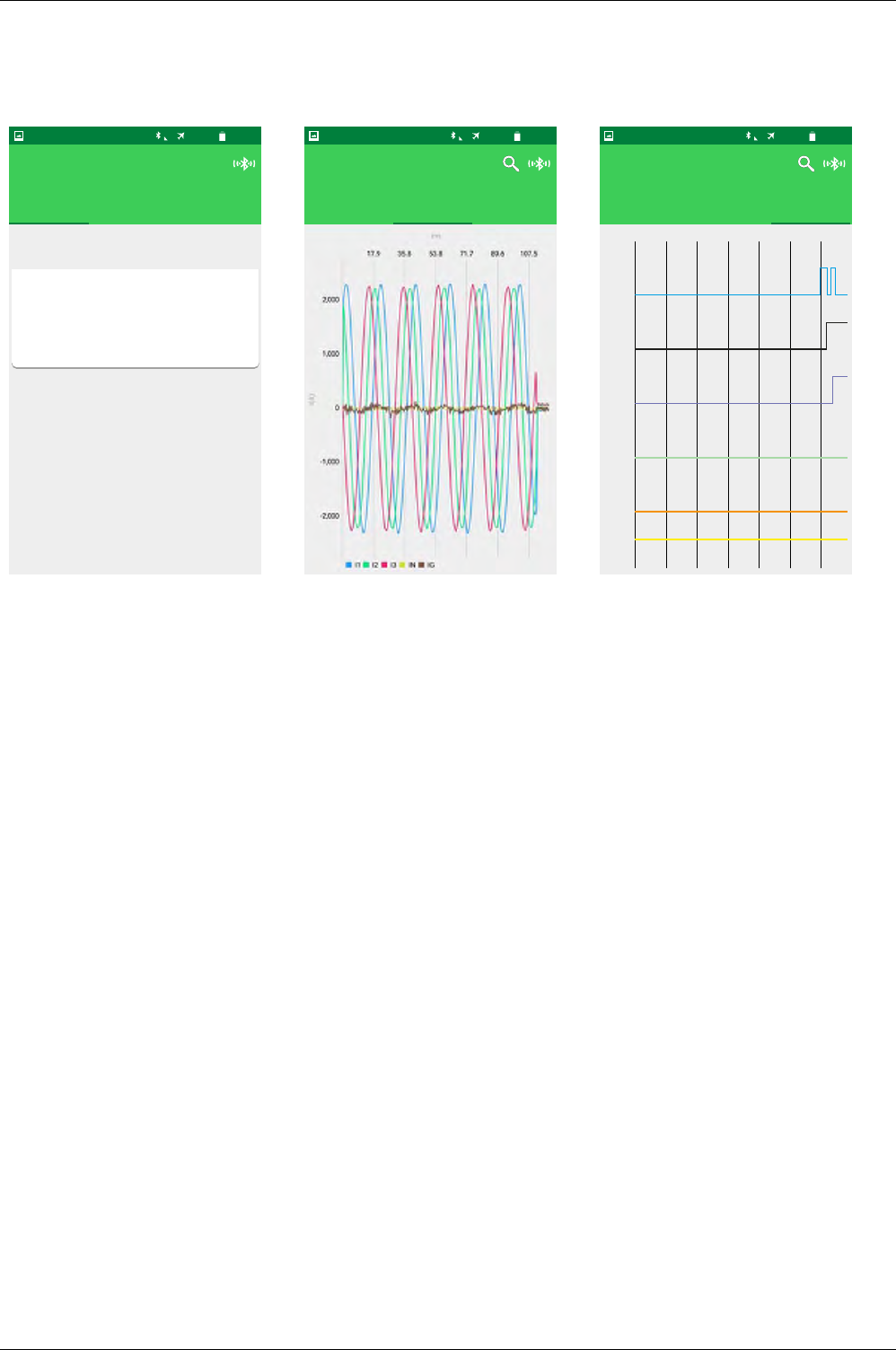
Diagnostic and Maintenance Functions
148 DOCA0102EN-00 05/2016
Examples of Screens
The following screens give examples of the type of information available on the Waveform Capture on Trip
Event Digital Module:
ÅWaveform Capture
MTZ2 10 MAIN
DETAIL ANALOGIC DIGITAL
Name ct_wfc1
Trip date 14/1/2000
Station Electropole
name
File type binary
76% 13:51N
ÅWaveform Capture
MTZ2 10 MAIN
DETAIL ANALOGIC DIGITAL
76% 13:51N
ÅWaveform Capture
MTZ2 10 MAIN
DETAIL ANALOGIC DIGITAL
76% 13:51N
17.4
DLO
TRIP
SDE
OPEN
ZSI_out
ZSI_in
34.8 52.2 69.6 87.0 104.4

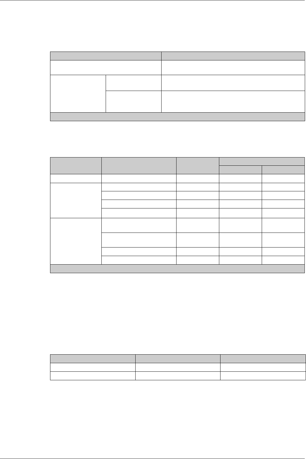
Operation Functions
150 DOCA0102EN-00 05/2016
Control Modes
Control Mode Settings for Micrologic X
The following table summarizes the available control modes for operating Masterpact MTZ circuit breakers
with Micrologic X control units:
Operation According to Control Mode Configured
The following table summarizes the opening and closing operations available, depending on the control
mode configured:
Configuring the Control Mode
The function can be set in the following ways:
With Masterpact MTZ mobile App running the Masterpact Operation Assistant Digital Module
On the Micrologic X display screen, at Home → Configuration → Communication → Control Mode →
Mode (Manual or Auto)
With Ecoreach software
Predefined Events
The following events are generated when control mode settings are changed:
Control Modes Description
Manual Only manual opening and closing of the circuit breaker by local
mechanical buttons is accepted.
Auto Local In addition to accepting manual orders, enables open/close
commands to be sent through Bluetooth, USB or IO module1
Remote In addition to accepting manual orders, enables open/close
commands to be sent through Modbus/TCP, IFE/EIFE webpages
or IO module1
1 According to IO input mode setting
Type of order Delivery Manual Auto
Local Remote
Mechanical Pushbutton X X X
Electrical BPFE X X X
BPFET ? X ?
Point to point (voltage release) – X X
IO module – X1X1
Through
Communication
Ecoreach software through USB
connection
–X–
Masterpact MTZ mobile App
through Bluetooth
–X–
Ethernet Modbus/TCP – – X
Webpages – – X
1 According to IO input mode setting
Event message History Severity
Manual mode enabled Operation Low
Local mode enabled Operation Low
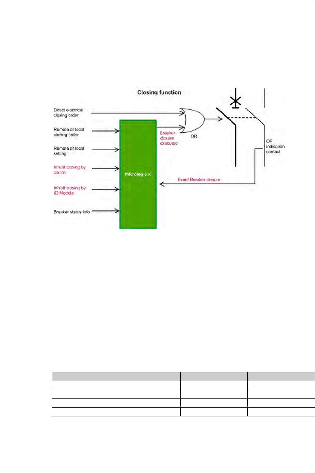
Operation Functions
DOCA0102EN-00 05/2016 151
Closing Function
Presentation
Micrologic X control units receive and process electrical closing orders. An event is generated on closure.
Operating Principle
Closing orders can be sent in the following ways:
Through a voltage release (direct electrical closing order)
Through a local or remote order, which is managed by the Micrologic X control unit
Management of Closing Function
Micrologic X control units manage closing orders issued by the following means:
BPFET connected to Micrologic X control unit
IO module breaker operation
Ecoreach via USB connection
Masterpact MTZ mobile App via Bluetooth
TCP via Ethernet Modbus
IFE/EIFE webpages
Inhibiting the Closing Function
The closing functions can be inhibited by sending a command through:
The communication network via Ethernet Modbus/TCP
The IO module
Predefined Events
The following events are generated by the closing function:
Event message History Severity
Circuit breaker moved from open to close position Operation Low
Circuit Breaker failed to open/close Diagnostic Medium
Close inhibited by communication Operation Low
Close inhibited by wired input Operation Low
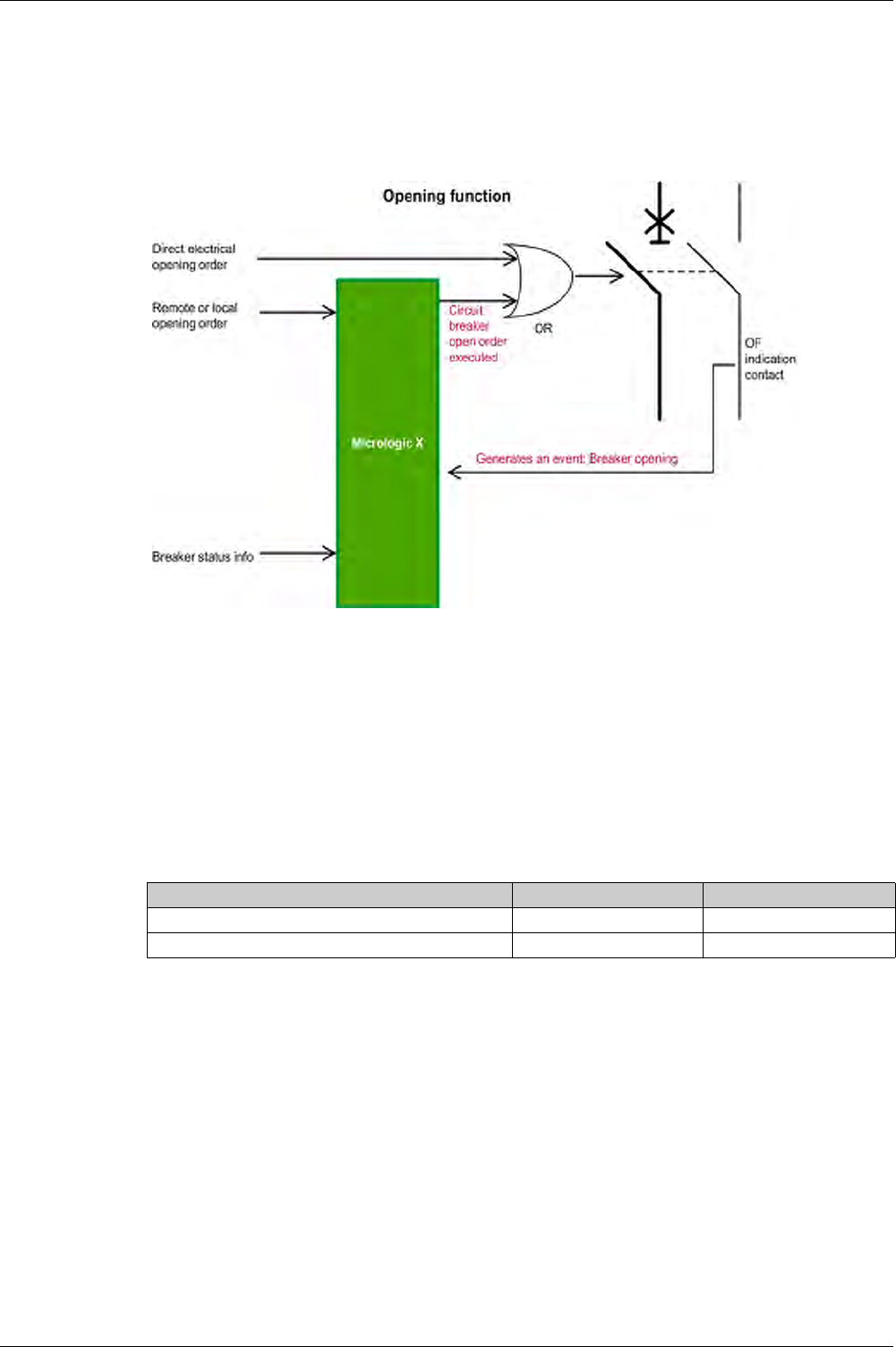
Operation Functions
152 DOCA0102EN-00 05/2016
Opening Function
Presentation
Micrologic X control units receive and process electrical opening orders. An event is generated on opening.
Operating Principle
Management of Opening Function
Micrologic X manages closing orders issued by the following means:
IO module breaker operation
Ecoreach via USB connection
Masterpact MTZ mobile App via Bluetooth
TCP via Ethernet Modbus
IFE/EIFE web pages
Predefined Events
The following events are generated by the opening function:
Event message History Severity
Circuit breaker moved from close to open position Operation Low
Circuit Breaker failed to open/close Diagnostic Medium

DOCA0102EN-00 05/2016 153
Micrologic X
Commu nication Func tions
DOCA0 102EN-00 05/2016
Communication Functions
Chapter 7
Communication Functions
What Is in This Chapter?
This chapter contains the following topics:
Topic Page
Bluetooth Low Energy Communication 154
NFC Communication 156
IEEE 802.15.4 Communication 157
USB Connection 159
Cybersecurity Recommendations 160

Communication Functions
154 DOCA0102EN-00 05/2016
Bluetooth Low Energy Communication
Description
Using Bluetooth Low Energy (BLE communications, you can access the Micrologic X control unit from a
smartphone running Masterpact MTZ mobile App
(seepage15)
. This application offers a task-oriented
interface with the control unit. In particular, you can:
Consult an overview of the main parameters of the circuit breaker
Get detailed information on measurements, alarms and events, health state and current status of the
circuit breaker
Consult and modify protection settings
Set the date and time parameters
Set the protection parameters
Share data by email
You can establish a Bluetooth connection with only one Micrologic X control unit at the same time. During
the connection, the control unit is identified by the last digits of its serial number.
Note that you can consult data and send orders but you cannot download and save data on your
smartphone.
Digital modules allow you to extend the features of the Micrologic X control unit and Masterpact MTZ
mobile App.
Prerequisites for Using Bluetooth
The prerequisites for establishing a Bluetooth connection are:
The Micrologic X control unit must be powered.
Bluetooth communication must be enabled on the control unit.
You must have a smartphone with Masterpact MTZ mobile App installed.
You must have access to the Micrologic X control unit, and be physically within range (usually within 20
to 30 meters or yards) for the duration of the connection.
NOTE: If using a backup power supply for the Micrologic X control unit, some functions such as operating
the circuit breaker might not be available.
Enabling and Disabling Bluetooth Communication
By default, Bluetooth communication is disabled.
You can enable or disable Bluetooth communication as follows:
On the Micrologic X display screen, go to Configuration → Communication → Bluetooth, and set
Bluetooth to ON or OFF.
With Ecoreach software, go to Configuration → Communication → Bluetooth, and set
Bluetooth activation to OFF.
An event is generated each time Bluetooth communication is enabled or disabled.
Setting the Bluetooth Disconnection Timer
When Bluetooth communication is enabled, there is a timer on the connection with a smartphone that ends
the communication after a period of idle time. By default, this automatic disconnection timer is set to 15
minutes.
You can change the setting for the Bluetooth disconnection timer as follows:
On the Micrologic X display screen, go to Configuration → Communication → Bluetooth, set Bluetooth
to ON, and then set the BLE timer (min) value.
With Ecoreach software, go to Configuration → Communication → Bluetooth, and set
Bluetooth time out delay (min) to the appropriate value.
You can set the value from 5 to 60 minutes (default = 15 minutes) in increments of 1.
Establishing a Bluetooth Connection
Follow the steps below to establish a Bluetooth connection from your smartphone to the Micrologic X
control unit.
Step Action
1 Start Masterpact MTZ mobile App on your smartphone.
2 Select Connect to device through Bluetooth.

Communication Functions
DOCA0102EN-00 05/2016 155
While your smartphone remains within the communication range (20 to 30 meters or yards from the
Micrologic X control unit), the Bluetooth connection remains active and the information displayed is
refreshed.
NOTE: Each connection is unique, you cannot save the connection parameters for your next Bluetooth
connection.
Bluetooth LED
The Bluetooth LED on the front face of the Micrologic X control unit can be:
ON: A Bluetooth connection procedure is in progress.
OFF: Bluetooth is in idle mode or disabled.
Blinking: A Bluetooth connection is established and active.
NOTE: The Bluetooth LED does not indicate whether the Bluetooth communication feature is enabled or
disabled in the Micrologic X control unit. When this feature is disabled, the LED does not light up when you
press the Bluetooth activation button.
About Bluetooth Low Energy in Micrologic X Control Unit
Troubleshooting Bluetooth Commmunication Issues
The table below lists the common problems you might meet when establishing a Bluetooth connection to
the Micrologic X control unit.
3 On the Micrologic X control unit, press the Bluetooth activation pushbutton. The Bluetooth LED
lights up. If it does not, you must enable the Bluetooth communication feature first.
On your smartphone, Masterpact MTZ mobile App starts scanning and displays a list of
Bluetooth devices in the neighborhood.
4 Select the Micrologic X control unit to which you want to connect.
A 6-digit pairing code is displayed on the Micrologic X display screen.
5 Enter the pairing code in Masterpact MTZ mobile App within 30 seconds.
If the pairing code is incorrect, or if more than 30 seconds have elapsed, Bluetooth
communication is deactivated (the LED turns off), and you must start the connection
procedure again at Step 3.
If the connection is established, the Bluetooth LED starts blinking.
6 To end the connection, you can either:
Press the Bluetooth pushbutton on the Micrologic X control unit.
Disconnect from Masterpact MTZ mobile App.
Step Action
Problem description Probable causes Solutions
The LED does not light up when you
press the BLE pushbutton on the
Micrologic X control unit
The Bluetooth function is not
enabled in the Micrologic X control
unit
The Micrologic X control unit is not
powered
Enable Bluetooth communication
in the Micrologic X control unit
Check the power supply of the
Micrologic X control unit
The Bluetooth connection was
established but the signal is lost
The smartphone has been moved
out of range
Perturbation in electromagnetic
compatibility
Place the smartphone within the
range for Bluetooth and establish a
new connection
Check whether another
Micrologic X control unit within
range is also activated. If so,
deactivate it and establish a new
connection
A smartphone is already connected to
the Micrologic X control unit

Communication Functions
156 DOCA0102EN-00 05/2016
NFC Communication
Description
Using near field communication (NFC), you can access the Micrologic X control unit from a smartphone
running Masterpact MTZ mobile App. With NFC, you can access the control unit and download data to your
smartphone, even when the control unit is not powered.
You can establish an NFC connection with only one Micrologic X control unit at the same time.
NOTE: NFC communication is only accessible from the Android version of the Masterpact MTZ mobile
App.
NFC communication is always enabled and cannot be disabled.
Prerequisites for Using NFC
The prerequisites for establishing an NFC connection are:
You must have a smartphone with Masterpact MTZ mobile App installed.
You must have physical access to the Micrologic X control unit.
Establishing an NFC Connection
Follow the steps below to establish an NFC connection from your smartphone to the Micrologic X control
unit.
NOTE: You must not remove your smartphone from the Micrologic X display screen while the data
download is in progress or you will lose the NFC connection.
NFC data downloaded from the Micrologic X control unit is not automatically refreshed. To get updates,
you must establish a new NFC connection. Be aware that each new set of data downloaded overwrites the
previous data. You can use the Masterpact MTZ mobile App to consult downloaded data.
About NFC in Micrologic X Control Unit
Step Action
1 Start Masterpact MTZ mobile App on your smartphone.
2 Select Connect to device through NFC.
3 Place your smartphone against the Micrologic X display screen, in the NFC wireless
communication zone.
A beep indicates that the communication is established. The Masterpact MTZ mobile App then
starts downloading data. Another beep indicates that the data download is complete.
If the operation fails, a message is displayed. Start the procedure again.
4 Remove your smartphone from the Micrologic X display screen.
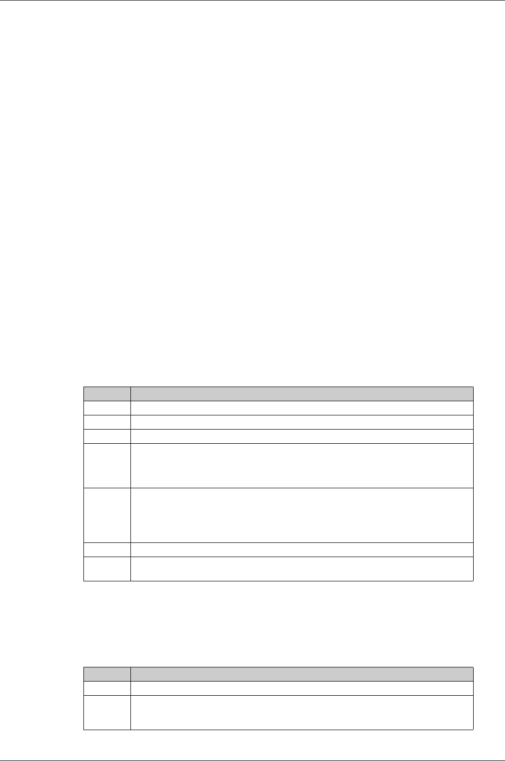
Communication Functions
DOCA0102EN-00 05/2016 157
IEEE 802.15.4 Communication
Description
When your installation includes the Com’X data logger and Ethernet gateway, you can set up wireless
IEEE 802.15.4 communication between this gateway and the Micrologic X control unit. When the
communication is set up, data about key Micrologic X parameters is automatically transferred to theCom’X
every minute. Data transferred over IEEE 802.15.4 is crypted using AES 128 bit encryption.
You can connect up to two Micrologic X control units to one Com’X gateway.
IEEE 802.15.4 communication between the Com’X gateway and the Micrologic X control unit can replace
an Ethernet LAN for monitoring your industrial network. The Com’X gateway is accessible from anywhere
over the Ethernet LAN.
Prerequisites for Using IEEE 802.15.4
The prerequisites for establishing an IEEE 802.15.4 connection are:
The Micrologic X control unit must be powered. The power supply modes are:
CPS high
VPS
USB
Vaux
IEEE 802.15.4 communication between the Micrologic X control unit and the Com’X gateway must be
commissioned.
You must have access to the Com’X gateway over an Ethernet LAN.
Commissioning IEEE 802.15.4 Communication
The IEEE 802.15.4 connection between the Micrologic X control unit and the Com’X gateway is set up
once at the time of commissioning and is valid thereafter. You can pair up to two Micrologic X control units
with one Com’X gateway.
Follow the steps below to commission IEEE 802.15.4 communication between the Com’X gateway and the
Micrologic X control unit.
Decommissioning IEEE 802.15.4 Communication
The IEEE 802.15.4 connection between the Micrologic X control unit and the Com’X gateway is valid until
it is removed by unpairing the devices.
Follow the steps below to decommission IEEE 802.15.4 communication between the Com’X gateway and
the Micrologic X control unit.
Step Action
1 From the Com’X web page, create the IEEE 802.15.4 network.
2 Activate the IEEE 802.15.4 signal and launch the discovery of IEEE 802.15.4 emitting devices.
3 Start Ecoreach on a laptop connected to the USB port of the Micrologic X control unit.
4 On the Configuration tab, under the Communication section, click Start scanning IEEE 802.15.4
devices to start the scan to detect the Com’X unit.
IEEE 802.15.4 is automatically activated in the Micrologic X control unit, the scan begins, and
Ecoreach displays the list of detected IEEE 802.15.4 networks within the radio range.
5 From the list, select the Extended PAN ID corresponding to the Com’X device and click Pair to
confirm pairing.
A popup box is displayed to report that IEEE 802.15.4 pairing was successful. The Micrologic X
control unit joins the IEEE 802.15.4 network of the Com’X, and starts sending data over the
network.
6 In Ecoreach, check the link quality indicator (LQI) for the IEEE 802.15.4 signal.
7 On the Com’X web page, check the pairing and IEEE 802.15.4 indicators. You can also consult
the data sent by the Micrologic X control unit over the IEEE 802.15.4 connection.
Step Action
1 Start Ecoreach on a laptop connected to the USB port of the Micrologic X control unit.
2 On the Configuration tab, under the Communication section, click Unpair in the IEEE 802.15.4
area. Click Yes in the popup window to confirm unpairing.
IEEE 802.15.4 is automatically disabled in the Micrologic X control unit.

Communication Functions
158 DOCA0102EN-00 05/2016
Enabling and Disabling IEEE 802.15.4 Communication
By default, IEEE 802.15.4 communication is disabled in the Micrologic X control unit. when it is delivered.
After commissioning, you can enable or disable IEEE 802.15.4 communication at any time as follows:
On the Micrologic X display screen, go to Configuration → Communication → IEEE 802.15.4, and set
IEEE 802.15.4 to ON or OFF.
With Ecoreach software, go to Configuration → Communication → IEEE 802.15.4, and set
IEEE 802.15.4 activation to ON or OFF.
Note that:
You cannot enable IEEE 802.15.4 on the Micrologic X control unit if IEEE 802.15.4 communication has
not been commissioned as explained previously.
Even when you disable IEEE 802.15.4 communication, the pairing between the Micrologic X control unit
and the Com’X gateway remains valid until you decommission or unpair the devices.
When you disable IEEE 802.15.4 communication, data transfers between the Micrologic X control unit
and the Com’X gateway stop.
An event is logged in the Com’X log book each time IEEE 802.15.4 communication is enabled or disabled.
IEEE 802.15.4 Network Status
IEEE 802.15.4 network status is displayed in Ecoreach at Configuration → Trip unit functioning → Wireless
communication access.
The following IEEE 802.15.4 states can be displayed in the IEEE 802.15.4 network status field:
Network None: indicates that the Micrologic X control unit is not commissioned, and not in the process
of being commissioned
Network Discovering: indicates that a scan is in progress to detect IEEE 802.15.4 devices within range
Network Discovery Complete: indicates that the scan is complete and a list of discovered devices is
displayed
Networking: indicates that the pairing process is in progress
Networked: indicates that IEEE 802.15.4 the Micrologic X control unit is commissioned
About IEEE 802.15.4 in Micrologic X Control Unit
The characteristics of IEEE 802.15.4 communication are:
Radio frequency 2.4 GHz, IEEE 802.15.4
Encryption and authentication AES 128 bits
“Listen before talk” (carrier sense multiple access with collision avoidance CSMA/CA)
Troubleshooting IEEE 802.15.4 Commmunication Issues
3 Check the network status indicator for IEEE 802.15.4, and the link quality indicator (LQI).
4 On the Com’X web page, check the unpairing.
Step Action

Communication Functions
DOCA0102EN-00 05/2016 159
USB Connection
Description
From a PC that runs Ecoreach software, you can access all of the monitoring and control functions of the
Micrologic X control unit. You can connect a laptop directly to the mini USB port of the control unit.
Connecting a PC with Ecoreach to USB Port
Follow the steps below to connect to the Micrologic X control unit using the mini USB port. This procedure
assumes that you have the appropriate cable (reference LV850067).
About Mini USB in Micrologic X Control Unit
Troubleshooting USB Connection Issues
Step Action
1 Connect your laptop PC to the mini USB port of the Micrologic X control unit using a cable with
reference LV850067.
The PC provides power to the Micrologic X control unit if necessary.
2 Start Ecoreach on the PC and log in.
3...
4
5
6

Communication Functions
160 DOCA0102EN-00 05/2016
Cybersecurity Recommendations
Overview
The Masterpact MTZ circuit breaker with its Micrologic X control unit is a key component of your
installation. The multiple communication features it offers bring greater efficiency and flexibility in
managing your installation, however they also make it potentially vulnerable to cyber attacks.
This section lists some of the elementary precautions that you must take to protect the communications
paths that give access to information about your installation, and control over it.
The communication paths to protect include:
Wireless Bluetooth communication
Wireless NFC communication
Wireless IEEE 802.15.4 communication
The mini USB port
The Ethernet LAN when the EIFE or IFE interface is present
For more detailed information on cybersecurity for the Masterpact MTZ, refer to
Masterpact MTZ - Cyber
Security Guide
.
For general guidelines on securing remote access to your network and for implementing a secure
operating environment, refer to
How Can I... Reduce Vulnerability to Cyber Attacks?
.
Cybersecurity Recommendations for Bluetooth Communication
To protect access to functions accessible through Bluetooth, it is recommended to:
Disable Bluetooth communications, as explained in Enabling or Disabling Bluetooth Communication
(see page 154)
.
Set the Bluetooth automatic disconnection timer to 5 minutes.
Keep locked the enclosure where the Masterpact MTZ is located, so that no unauthorized person can
change the settings on the Micrologic X control unit.
Limit the number of users allowed to have the Masterpact MTZ mobile App installed on their
smartphones.
Make sure that the smartphones that have the Masterpact MTZ mobile App are password protected and
used for work only.
Do not give away information about the smartphone (telephone number, MAC address) if it is not
necessary.
Disconnect the smartphone from the Internet during a Bluetooth connection with the Micrologic X
control unit.
Do not store confidential or sensitive information on smartphones.
Cybersecurity Recommendations for NFC Communication
To protect access to data accessible through NFC, it is recommended to:
Keep locked the enclosure where the Masterpact MTZ is located, so that no unauthorized person can
change the settings on the Micrologic X control unit.
Limit the number of users allowed to have the Masterpact MTZ mobile App installed on their
smartphones.
Make sure that the smartphones that have the Masterpact MTZ mobile App are password protected and
used for work only.
WARNING
POTENTIAL COMPROMISE OF SYSTEM AVAILABILITY, INTEGRITY, AND CONFIDENTIALITY
Change default passwords to help prevent unauthorized access to device settings and information.
Disable unused ports and default accounts to help minimize pathways for malicious attackers.
Place networked devices behind multiple layers of cyber defenses (such as firewalls, network
segmentation, and network intrusion detection and protection).
Use industry-accepted Informational Technology (IT) and Operational Technology (OT) cybersecurity
practices to help prevent loss or exposure of data, modification or deletion of logs and data, and
interruption of services.
Failure to follow these instructions can result in death, serious injury, or equipment damage.

Communication Functions
DOCA0102EN-00 05/2016 161
Cybersecurity Recommendations for IEEE 802.15.4 Communication
Data transfers using IEEE 802.15.4 communication are crypted, therefore, the risk of an unauthorized
person gaining access to confidential information during transmission is limited. Mostly, if IEEE 802.15.4
is the only way of accessing information about the Micrologic X remotely, you must protect the
IEEE 802.15.4 connection itself.
It is recommended to:
Keep locked the enclosure where the Masterpact MTZ is located, so that no unauthorized person can
disable IEEE 802.15.4 communication on the Micrologic X control unit.
Protect the Micrologic X control unit from electromagnetic interference that could perturb the
IEEE 802.15.4 communication.
Design and implement security rules for remote access to your network, in particular to the Com’X.
Cybersecurity Recommendations for USB Connection
To protect access to functions accessible through a USB connection on the Micrologic X control unit, it is
recommended to:
Keep locked the enclosure where the Masterpact MTZ is located, so that no unauthorized person can
access the Micrologic X control unit.
Limit the number of users allowed to use Ecoreach or other monitoring software.
Make sure that the PCs running the monitoring software are hardened following the guidelines provided
in
Masterpact MTZ - Cyber Security Guide
, and the most up-to-date hardening methods for the
operating system running on your PCs.
Cybersecurity Recommendations for an Ethernet LAN
When the Micrologic X IMU includes the EIFE module or the IFE module to connect it to the Ethernet LAN,
to protect access to the Micrologic X control unit, it is recommended to:
Limit the number of users allowed to use Ecoreach or other monitoring software.
Make sure that the PCs running the monitoring software are hardened following the guidelines provided
in
Masterpact MTZ - Cyber Security Guide
, and the most up-to-date hardening methods for the
operating system running on your PCs.
...

Communication Functions
162 DOCA0102EN-00 05/2016

DOCA0102EN-00 05/2016 163
Micrologic X
Event Ma nagement
DOCA0 102EN-00 05/2016
Event Mana gement
Chapter 8
Event Management
What Is in This Chapter?
This chapter contains the following topics:
Topic Page
Event Management 164
Event Status Overview 165
Event Notifications 169
Event Status Table 170
Event History 171
Event List 173
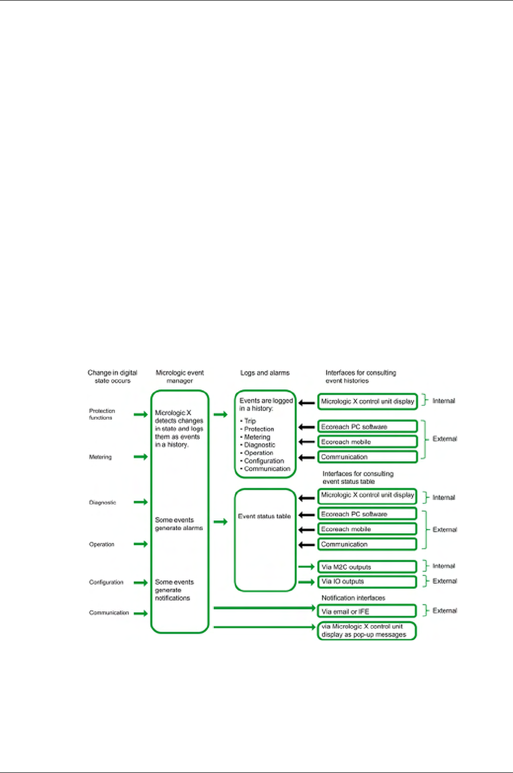
Event Management
164 DOCA0102EN-00 05/2016
Event Management
Definition
An event is a change in state of digital data, or any incident detected by the Micrologic X control unit, IFE
or EIFE Ethernet interface, or IO modules.
Events are time stamped and logged in the event history of each module.
Events are categorized according to a level of severity:
High
Medium
Low
All high and medium-level events generate an alarm and a pop-up notification screen
(see page 169)
on
the Micrologic X control unit display screen.
Low-level events are information-type events. They can be consulted through Ecoreach software.
Alarms and trips are events that require specific attention from the user:
A trip is an event generated when the circuit breaker trips.
An alarm is an event with medium or high severity.
The information in this chapter is valid for events detected by the Micrologic X control unit. Refer to the
following documents for events detected by the IFE or EIFE Ethernet interface, or by IO modules:
For information about IFE events, refer to the
IFE Ethernet Interface for LV Circuit Breaker - User Guide
For information about EIFE events, refer to the
EIFE Embedded Ethernet Interface for One
Masterpact MTZ Drawout Circuit Breaker - User Guide
For information about IO events, refer to the
IO Input/Output Application Module for One Circuit
Breaker - User Guide
Management of Events by Micrologic X Control Unit
The following diagram gives an overview of how events are managed by the Micrologic X control unit.
Event Time Stamping
Each event is time stamped with the date and time of the Micrologic X internal clock.
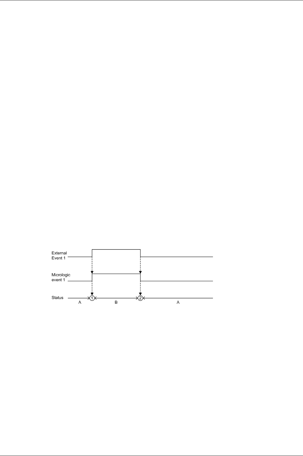
Event Management
DOCA0102EN-00 05/2016 165
Event Status Overview
Event Status Definition
The status of an event is
active
,
inactive
, or
held
. It depends on the event type and whether it is latched or
unlatched. The status of all events can be consulted at any time
(see page 170)
.
Event Type
Events can be the following types:
Occurrence/completion (on/off): Events which have a defined beginning and end, representing the
beginning or end of a system state. The occurrence and completion are both time-stamped and logged
in a history. For example, control unit overheating is an occurrence/completion event.
Instantaneous: Events with no duration. For example, the reception of an opening order, a change to
settings, or a circuit breaker trip are instantaneous events.
The event type cannot be customized.
Latched or Unlatched Events
An event can be unlatched or latched:
Unlatched: The event status is active while the cause of the event is present. It automatically returns to
inactive when the cause of the event disappears or is resolved.
Latched: The event status does not automatically return to inactive when the cause of the event
disappears or is resolved. It stays in the held state until it is reset by the user.
The latched/unlatched mode for certain events
(see page 173)
can be customized on Ecoreach software.
Disabling Events
Certain events can be disabled so that the event is not taken into consideration by the Micrologic X control
unit. In this case the event is not logged in a history and does not generate an alarm.
Events can be disabled through Ecoreach software. For more information about which events can be
disabled, refer to the event list
(see page 173)
. Events can be enabled again after being disabled.
Unlatched Occurrence/Completion Events
The following graph shows the event status for an unlatched occurrence/completion event.
A Event inactive
B Event active
1 Event occurrence: event is time stamped, logged in a history and notified, depending on severity
2 Event completion: event is time stamped and logged in a history
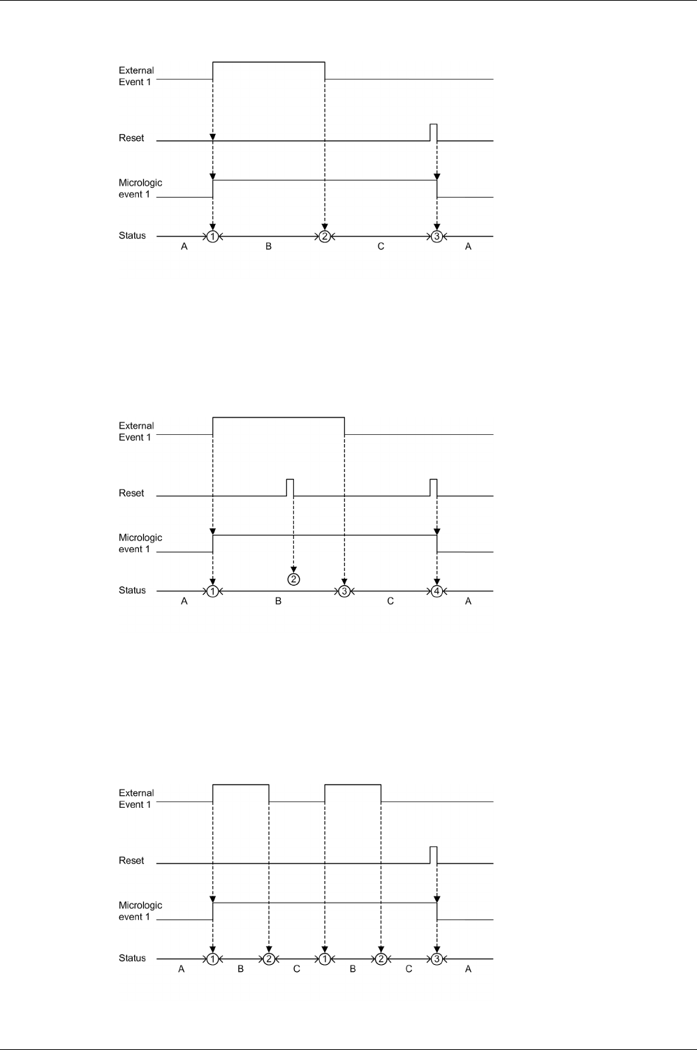
Event Management
166 DOCA0102EN-00 05/2016
Latched Occurrence/Completion Events
The following graph shows the event status for a latched occurrence/completion event.
A Event inactive
B Event active
C Event held
1 Event occurrence: event is time stamped, logged in a history and notified, depending on severity
2 Event completion: event is time stamped and logged in a history
3 Event reset: reset command is time stamped and logged in operation history. All held events are reset.
The following graph shows the event status for a latched event where a reset is attempted before
completion of the event.
A Event inactive
B Event active
C Event held
1 Event occurrence: event is time stamped, logged in a history and notified, depending on severity
2 Event reset: reset command is time-stamped and logged in the operation history but has no effect on Micrologic
event 1 as external event is not completed
3 Event completion: event is time stamped and logged in a history
4 Event reset: reset command is time stamped and logged in the operation history. All held events are reset.
The following graph shows the event status for a latched, recurring occurrence/completion event.
A Event inactive
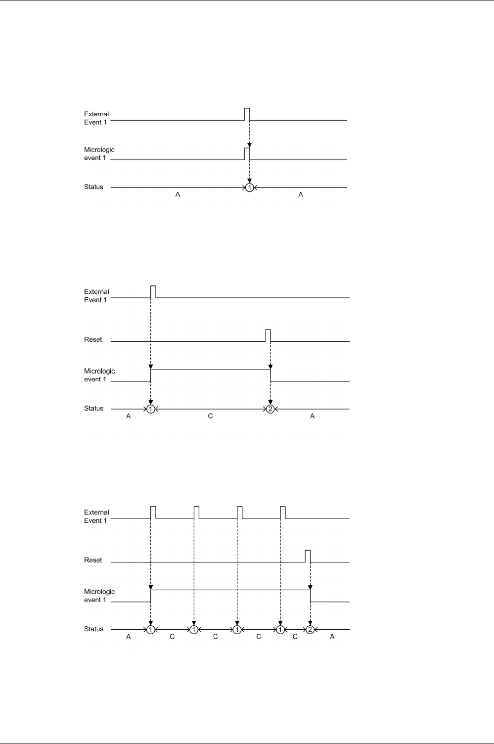
Event Management
DOCA0102EN-00 05/2016 167
B Event active
C Event held
1 Event occurrence: event is time stamped, logged in a history and notified, depending on severity
2 Event completion: event is time stamped and logged in a history
3 Event reset: reset command is time stamped and logged in the operation history. All held events are reset.
Unlatched Instantaneous Events
The following graph shows the event status for an unlatched instantaneous event.
A Event inactive
1 Event occurrence: event is time stamped, logged in a history and notified, depending on severity
Latched Instantaneous Events
The following graph shows the event status for a latched instantaneous event.
A Event inactive
C Event held
1 Event occurrence: event is time stamped, logged in a history and notified, depending on severity
2 Event reset: reset command is time stamped and logged in the operation history. All held events are reset.
The following graph shows the event status for a latched, recurring instantaneous event.
A Event inactive
C Event held
1 Event occurrence: event is time stamped, logged in a history and notified, depending on severity
2 Event reset: reset command is time stamped and logged in the operation history. All held events are reset.

Event Management
168 DOCA0102EN-00 05/2016
Resetting Events
Events can be reset in the following ways:
By pressing the Test/Reset button on the front of the Micrologic X control unit for 3–15 seconds.
With Ecoreach software.
With Masterpact MTZ mobile App.
By sending a reset command using the communication network. This function is password protected.
Reset commands do not target specific events. All held event states managed by the Micrologic X control
unit are reset, and all trip cause LEDs are cleared.
Reset commands target a specific module. For example, pressing the Test/Reset button for 3–15 seconds
resets the events of the Micrologic X control unit but does not reset the events of the IO module.
The reset command generates an event and it is logged in the operation history.

Event Management
DOCA0102EN-00 05/2016 169
Event Notifications
Presentation
Events that are notified in the following ways cannot be configured:
By a pop-up screen on the Micrologic X control unit (high and medium-level events).
By SDE1 standard fault-trip indication contact and SDE2 optional fault-trip indication contact (Trip
events).
All events can be configured to be notified in the following ways:
By optional M2C module.
By optional IO module.
By email from IFE or EIFE Ethernet interface.
Pop-up Screen
All high and medium-level events generate a pop-up screen on the Micrologic X display screen
(see page 57)
.
A red pop-up screen indicates a trip or high-level event, needing immediate attention.
An orange pop-up screen indicates a medium-level alarm, recommending action.
SDE Fault-Trip Indication Contacts
M2C Notifications
Ecoreach software allows the assignment of one or more events to each M2C output.
The M2C output remains on as long as one of the events assigned is active or held.
Ecoreach software also enables the status of the M2C outputs to be forced.
Forcing or unforcing a M2C output generates the following events:
M2C output 1 unforced / forced change.
M2C output 2 unforced / forced change.
IO Module Notifications
Ecoreach software allows the assignment of one or more events to IO module outputs available according
to the IO module predefined or user-defined applications selected. The IO module output remains on as
long as one of the events assigned is active or held. The operating mode of the IO module output must be
set as non-latching. Refer to the
IO Input/Output Application Module for One Circuit Breaker - User Guide
.
Email Notification
The occurrence of an event is notified by email, if configured to do so.
Email notifications have to be configured through the IFE or EIFE web pages. The notification by email is
not configured by default.
Refer to the
IFE Ethernet Interface for LV Circuit Breaker - User Guide
and the
EIFE Embedded Ethernet
Interface for One Masterpact MTZ Drawout Circuit Breaker - User Guide

Event Management
170 DOCA0102EN-00 05/2016
Event Status Table
Introduction
The event status table contains the status of all events at the time of consultation. The status can be
inactive, active or held.
Event status for active and held events is displayed:
On the Micrologic X display screen.
With Ecoreach software.
With the Masterpact MTZ mobile App.
The status of an event can be checked using the communication network.
Displaying the Event Status Table on the Micrologic X Display Screen
Display the event status table on the Micrologic X display screen at Home → Alarms/History → Alarms.
High and medium-level active and held events are displayed.
The events are displayed in no specific order, with the description of the event and the time it occurred.
If the event is completed while the screen is open, the message Completed is displayed on the screen.
Displaying the Event Status Table on Ecoreach Software
High and medium-level active and held events are displayed.
By default, events are sorted chronologically.
Events can be filtered by:
Severity:
Alarms: High-level events
Warnings: Medium-level events
Topic (History)
Once filtered, events can be sorted by other parameters, such as date, status, or message.
Displaying the Event Status Table on Masterpact MTZ mobile App
By default, events are sorted chronologically. They can be sorted by other parameters such as status,
history, message, date, or severity.

Event Management
DOCA0102EN-00 05/2016 171
Event History
Overview
All events are logged in one of the histories of the Micrologic X control unit:
Trip
Protection
Diagnostic
Metering
Configuration
Operation
Communication
All severities of events are logged, including low-level events.
The occurrence and completion of an event are logged as two separate events.
Events logged in histories are displayed as follows:
On the Micrologic X display screen
With Ecoreach software
With Masterpact MTZ mobile App
The event histories can be downloaded using the communication network.
The following information is logged in a history for each event:
Event ID: name or code or user message
Event type: occurrence/completion or pulse
Time stamp: date and time of occurrence/completion
Context data (only for certain events)
Number of Events in Each History
Each history has a predefined maximum size. When a history is full, each new event overwrites the oldest
event in the relevant history.
Displaying Event History on Micrologic X Display Screen
Only high-level and medium-level events logged in histories are displayed on the Micrologic X display
screen:
Display events logged in the trip history at Home → Alarms/History → Trip History
Display events logged in other histories at Home → Alarms/History → Alarm History
Events are displayed in chronological order, with the event name and time stamp, starting with the most
recent.
Only occurrences of occurrence/completion events are displayed.
Displaying Event History on Ecoreach Software
All events logged in histories are displayed on the Ecoreach software.
Events in histories are displayed in chronological order, starting with the most recent event.
Events can be sorted by using filters for the following criteria:
Date and time
Severity
History
Displaying Event History on Masterpact MTZ mobile App
All events logged in histories are displayed on the Masterpact MTZ mobile App.
Event history Number of events stored in history
Trip 50
Protection 100
Diagnostic 300
Metering 300
Configuration 100
Operation 300
Communication 100

Event Management
172 DOCA0102EN-00 05/2016
Events in histories are displayed in chronological order, starting with the most recent event.
Events can be sorted by the following criteria:
Date and time
Severity
History
Erase History Content
The content of all histories can be erased with Ecoreach software.
Erasing the history generates the following event: Event history deleted
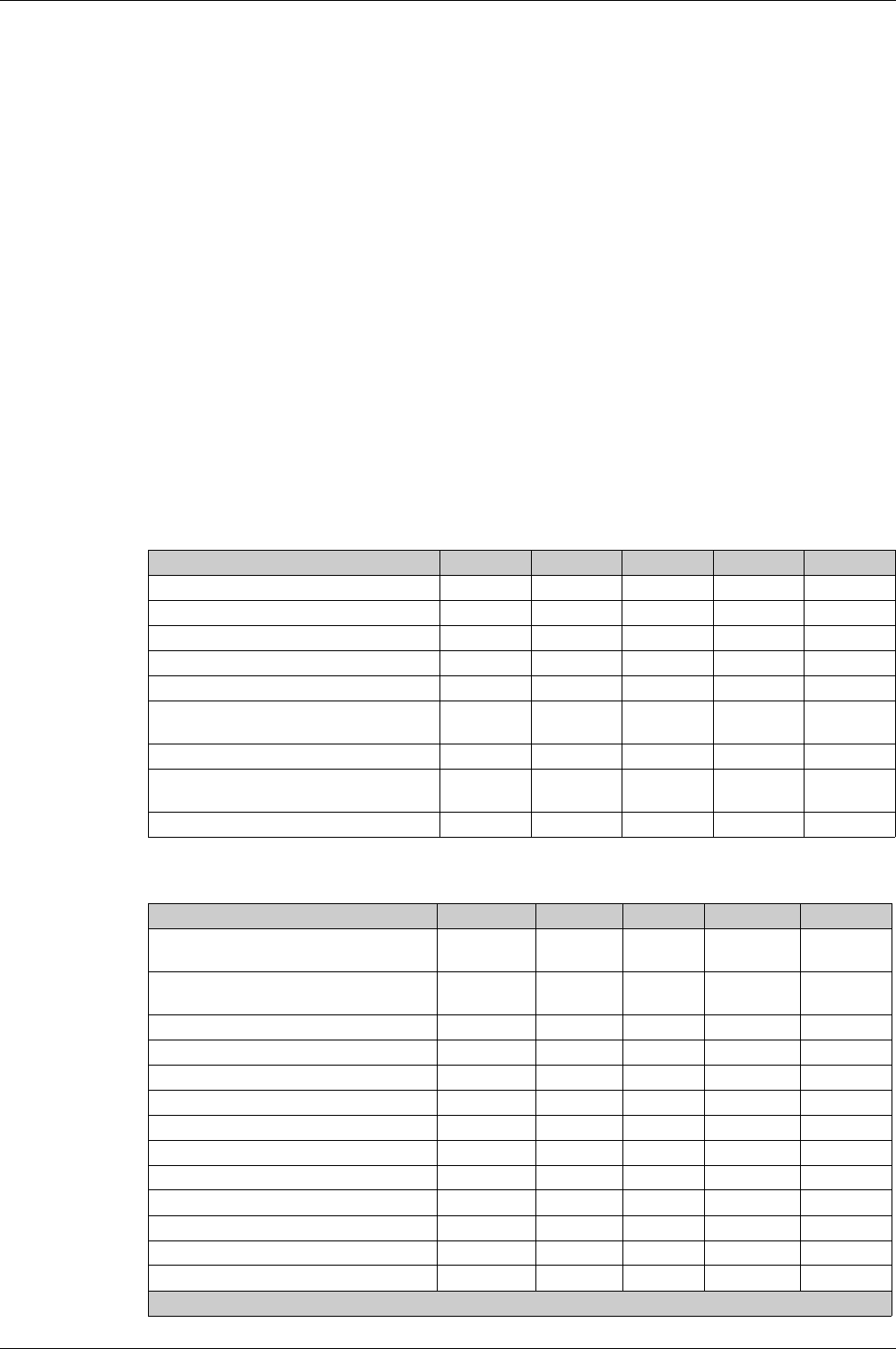
Event Management
DOCA0102EN-00 05/2016 173
Event List
Event Characteristics
The events are listed according to the history in which they are logged
(see page 171)
.
Each event is defined by the following characteristics:
User message: message displayed on Ecoreach software.
Type
(see page 165)
: not customizable
On/off: occurrence/completion event.
Instant: instantaneous event.
Latched
(see page 165)
: can be customized with Ecoreach software
Yes: the event is latched and the user must reset the event status.
No: the event is unlatched.
Activity
(see page 165)
:
Enabled: the event is always enabled.
Enabled1: the event is enabled by default and can be disabled with Ecoreach software.
Disabled1: the event is disabled by default and can be enabled with Ecoreach software.
Severity:
High-level trips and alarms.
Medium-level alarms.
Low-level events.
Trip Events
Protection Events
User message History Type Latched Activity Severity
Ir trip
(see page 65)
Trip Instant Yes Enabled High
Isd trip
(see page 68)
Trip Instant Yes Enabled High
Ii trip
(see page 70)
Trip Instant Yes Enabled High
Ig trip
(see page 72)
Trip Instant Yes Enabled High
IΔn trip
(see page 74)
Trip Instant Yes Enabled High
Ultimate self-protection trip (Sellim)
(see page 62)
Trip Instant Yes Enabled High
Internal failure trip Trip Instant Yes Enabled High
Ultimate self-protection trip (DIN/DINF)
(see page 62)
Trip Instant Yes Enabled High
IΔn / Ig test trip
(see page 73)
Trip Instant Yes Enabled High
User message History Type Latched Activity Severity
Ultimate self-protection (DIN/DINF) operate
(see page 62)
Protection On/off No Enabled Medium
Ultimate self-protection (Sellim) operate
(see page 62)
Protection On/off No Enabled Medium
Thermal memory reset order
(see page 65)
Protection Instant No Enabled Low
Ir prealarm (I>90%Ir)
(see page 67)
Protection On/off No Enabled Low
Ir start (I>105%Ir)
(see page 67)
Protection On/off No Enabled Medium
Ir operate
(see page 67)
Protection On/off No Enabled Medium
Isd start
(see page 69)
Protection On/off No Enabled Low
Isd operate
(see page 69)
Protection On/off No Enabled Medium
Ii operate
(see page 70)
Protection On/off No Enabled Medium
Ig start
(see page 72)
Protection On/off No Enabled Low
Ig operate
(see page 72)
Protection On/off No Enabled Medium
IΔn start
(see page 74)
Protection On/off No Enabled Low
IΔn operate
(see page 74)
Protection On/off No Enabled Medium
1 Customizable with Ecoreach software

Event Management
174 DOCA0102EN-00 05/2016
Diagnostic Events
B curve active
(see page 78)
Protection On/off No Enabled Low
Protection settings on local screen is
unlocked
(see page 63)
Protection On/off No1Enabled Low
Remote lock for protection settings is
unlocked
(see page 63)
Protection On/off No1Enabled Low
Protection setting change (display screen)
(see page 62)
Protection Instant No1Enabled Low
Protection setting changed (Bluetooth, USB
or IFE)
(see page 62)
Protection Instant No1Enabled Medium
User message History Type Latched Activity Severity
1 Customizable with Ecoreach software
User message History Type Latched Activity Severity
IO 1 module connection lost
(see page 142)
Diagnostic Instant Yes Enabled1Medium
IO 2 module connection lost
(see page 142)
Diagnostic Instant Yes Enabled1Medium
IFE connection lost
(see page 142)
Diagnostic Instant Yes Enabled1Medium
Product in test mode Diagnostic On/off No Enabled Low
Injection test Diagnostic On/off No Enabled Low
Test aborted by user Diagnostic Instant No Enabled Low
Product self test major malfunction
(see page 138)
Diagnostic On/off No Enabled High
Internal current sensors (CT) disconnected
(see page 138)
Diagnostic On/off No Enabled High
ENCT disconnected
(see page 138)
Diagnostic On/off No Enabled High
Earth leakage (Vigi) sensor disconnected
(see page 138)
Diagnostic On/off No Enabled High
Current protection reset to default settings
(see page 141)
Diagnostic On/off No Enabled High
Reading accessing protection settings error
(see page 141)
Diagnostic On/off No Enabled Medium
Metering and advanced protection
malfunction
(see page 141)
Diagnostic On/off No Enabled Medium
NFC malfunction
(see page 141)
Diagnostic On/off No Enabled1Medium
Display screen or wireless malfunction
(see page 141)
Diagnostic On/off No Enabled Medium
IEEE 802.15.4 malfunction
(see page 141)
Diagnostic On/off No Enabled1Medium
Bluetooth malfunction
(see page 141)
Diagnostic On/off No Enabled1Medium
Replace battery
(see page 141)
Diagnostic On/off No Enabled1Medium
Minor- Corrected ASIC internal error
warning
(see page 141)
Diagnostic On/off No Enabled Medium
FW internal error
(see page 141)
Diagnostic On/off No Enabled Low
Sensor plug reading error
(see page 141)
Diagnostic On/off No Enabled High
Minor-Open/Close coils failure
(see page 141)
Diagnostic On/off No Enabled Medium
Discrepancy ASIC configuration
(see page 141)
Diagnostic On/off No Enabled High
Critical hardware module discrepancy
(see page 141)
Diagnostic On/off No Enabled Medium
Critical firmware module discrepancy
(see page 141)
Diagnostic On/off No Enabled Medium
Non-critical hardware module discrepancy
(see page 141)
Diagnostic On/off No Enabled Medium
1 Customizable with Ecoreach software
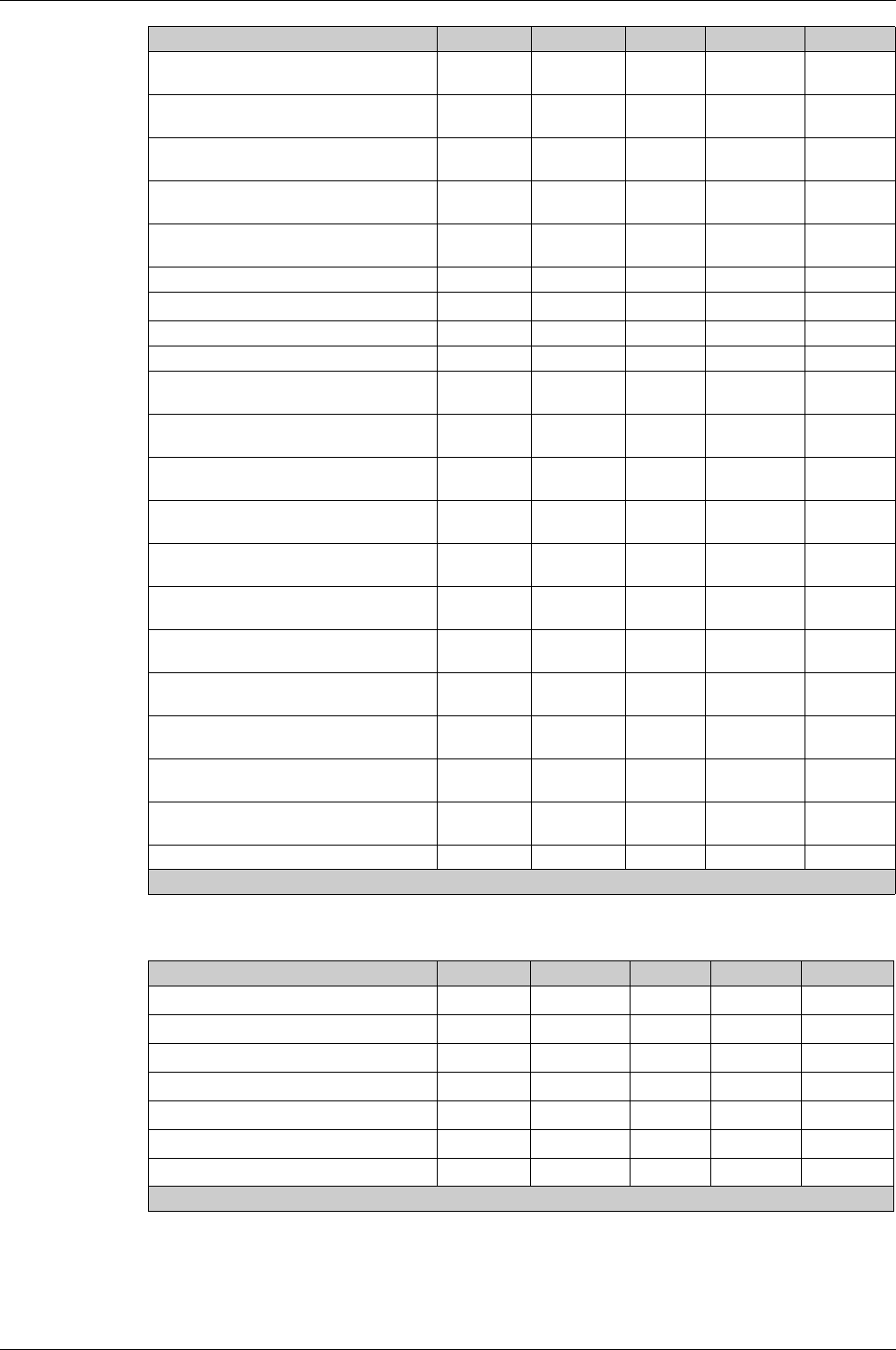
Event Management
DOCA0102EN-00 05/2016 175
Metering Events
Non-critical firmware module discrepancy
(see page 141)
Diagnostic On/off No Enabled Medium
ULP module address conflict
(see page 141)
Diagnostic On/off No Enabled Medium
Firmware discrepancy within product
(see page 141)
Diagnostic On/off No Enabled Medium
IΔn/Ig test trip failed (IΔn
(see page 74)
Ig
(see page 73)
)
Diagnostic Instant No Enabled High
IΔn/Ig test button pressed (IΔn
(see page 74)
Ig
(see page 73)
)
Diagnostic Instant No Enabled Low
ZSI Test
(see page 81)
Diagnostic Instant No Enabled Low
Contact 60% worn out
(see page 140)
Diagnostic On/off No Enabled1Medium
Contact 95% worn out
(see page 140)
Diagnostic On/off No Enabled Medium
Contact 100% worn out
(see page 140)
Diagnostic On/off No Enabled High
CB operations has passed 80% of service
life
(see page 143)
Diagnostic On/off No Enabled1High
CB operations has passed the service life
(see page 143)
Diagnostic Instant No Enabled Low
MX1 opening release malfunction
(see page 139)
Diagnostic On/off No Enabled Medium
MX1 opening release is no longer detected
(see page 139)
Diagnostic On/off No Enabled Medium
MCH has reached 80% of the max nb of
operations
(seepage139)
Diagnostic On/off No Enabled Medium
MCH has reached the max nb of operations
(see page 139)
Diagnostic On/off No Enabled Medium
XF closing release malfunction
(see page 139)
Diagnostic On/off No Enabled Medium
XF closing release is no longer detected
(see page 139)
Diagnostic On/off No1Enabled1Medium
MX2 / MN opening release malfunction
(see page 139)
Diagnostic On/off No Enabled High
MX2 / MN opening release is no longer
detected
(see page 139)
Diagnostic On/off No Enabled Medium
Circuit Breaker failed to Open/Close
(see page 139)
Diagnostic Instant Yes Enabled Medium
Event history deleted
(see page 172)
Diagnostic Instant No Enabled Low
User message History Type Latched Activity Severity
1 Customizable with Ecoreach software
User message History Type Latched Activity Severity
Reset Min/Max currents
(see page 116)
Metering Instant No1Enabled Low
Reset Min/Max voltages
(see page 116)
Metering Instant No1Enabled Low
Reset Min/Max power
(see page 116)
Metering Instant No1Enabled Low
Reset Min/Max frequency
(see page 116)
Metering Instant No1Enabled Low
Reset Min/Max harmonics
(see page 116)
Metering Instant No1Enabled Low
Reset Min/Max power factor
(see page 116)
Metering Instant No1Enabled Low
Reset energy counters
(see page 122)
Metering Instant No1Enabled Low
1 Customizable with Ecoreach software
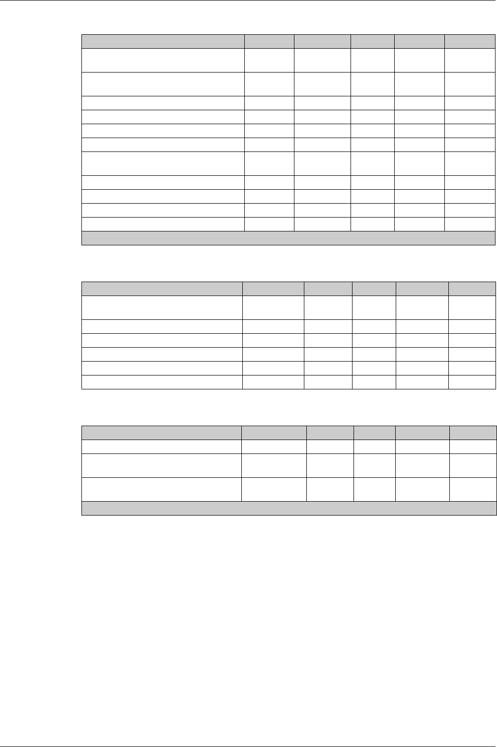
Event Management
176 DOCA0102EN-00 05/2016
Operation Events
Configuration Events
Communication Events
User message History Type Latched Activity Severity
CB moved from close to open position
(see page 152)
Operation Instant No1Enabled1Low
CB moved from open to close position
(see page 151)
Operation Instant No1Enabled1Low
Closing release activation
(see page 151)
Operation Instant No Enabled Low
Opening release activation
(see page 152)
Operation Instant No Enabled Low
Manual mode enabled
(see page 150)
Operation On/off No Enabled Low
Local mode enabled
(see page 150)
Operation On/off No Enabled Low
Close inhibited by communication
(see page 151)
Operation On/off No Enabled Low
Close inhibited by wired input
(see page 151)
Operation On/off No Enabled Low
M2C output 1 forced
(see page 169)
Operation On/off No Enabled Low
M2C output 2 forced
(see page 169)
Operation On/off No Enabled Low
Alarm reset (trip and non-trip)
(see page 168)
Operation Instant No Enabled Low
1 Customizable with Ecoreach software
User message History Type Latched Activity Severity
Conflict with IO module configuration
(see page 142)
Configuration On/off No Enabled Medium
Product in upgrade mode Configuration On/off No Enabled Low
Product upgrade failed Configuration Instant No Enabled Medium
Clock setup
(see page 22)
Configuration Instant No Enabled Low
License installed
(see page 21)
Configuration Instant No Enabled Low
License uninstalled
(see page 21)
Configuration Instant No Enabled Low
User message History Type Latched Activity Severity
USB connection
(see page 159)
Communication On/off No Enabled Low
BLUETOOTH communication enabled
(see page 154)
Communication On/off No Enabled1Low
IEEE 802.15.4 communication enabled
(see page 157)
Communication On/off No Enabled1Low
1 Customizable with Ecoreach software

DOCA0102EN-00 05/2016 177
Micrologic X
DOCA010 2EN-00 05/ 2016
Appendices

178 DOCA0102EN-00 05/2016

DOCA0102EN-00 05/2016 179
Micrologic X
Abbreviat ed title of Chap ter
DOCA0 102EN-00 05/2016
Title of Chapt er
Appendix A
Title of Chapter