Schneider Electric Systems Canada EB450-XXF01 Remote Radio Data Modem Base/Repeater User Manual EB Quick Start Guide pmd
Trio Datacom Pty Ltd (a wholly owned company of Schneider Electric) Remote Radio Data Modem Base/Repeater EB Quick Start Guide pmd
Contents
EB Quick Start Guide
Quick Start Guide - EB450 Base Station 1
QuicQuic
QuicQuic
Quick Stark Star
k Stark Star
k Start Guidet Guide
t Guidet Guide
t Guide
EB450 Base StaEB450 Base Sta
EB450 Base StaEB450 Base Sta
EB450 Base Stationtion
tiontion
tion
1.0 Introduction
Welcome to the Quick Start Guide for the EB450 Base /
Repeater Data Radio. This guide provides step-by-step
instructions, with simple explanations to get you up-and-
running. For further information, please refer to the E
Series User Manual. Related Products and Documentation
•Remote Data Radio ER450
•Hot Standby Base Station EH450
•Digital Order Wire Voice Module EDOVM
•Duplexers
•TVIEW+ Management Suite
•E Series User Manual
Contents
1.0 Introduction............................................................ 1
2.0 Mounting and Environmental Considerations........ 2
3.0 Connecting Antennas and RF Feeders.................. 3
4.0 Communications Ports........................................... 4
5.0 Power Supply Requirements..................................5
6.0 TVIEW+ Management Suite...................................7
7.0 Optimising the Antenna for VSWR......................... 6
8.0 LED Indicators and Test Outputs........................... 6
9.0 Bar Graph Indicators.............................................. 7
10.0 Support Options..................................................... 8 Fig 1
2Quick Start Guide - EB450 Base Station
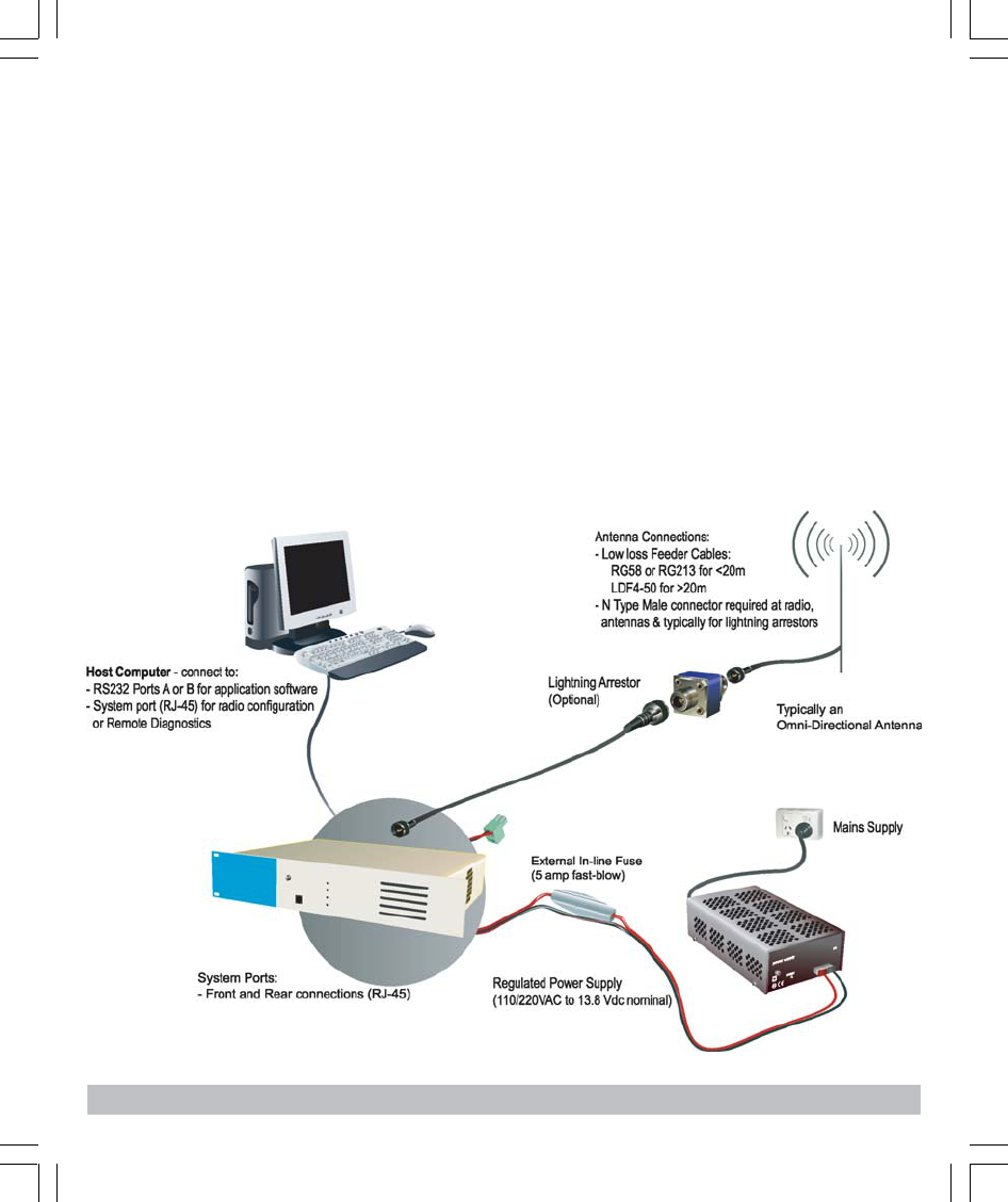
2.1 Typical Radio Setup
2.0 Mounting and Environmental
Considerations
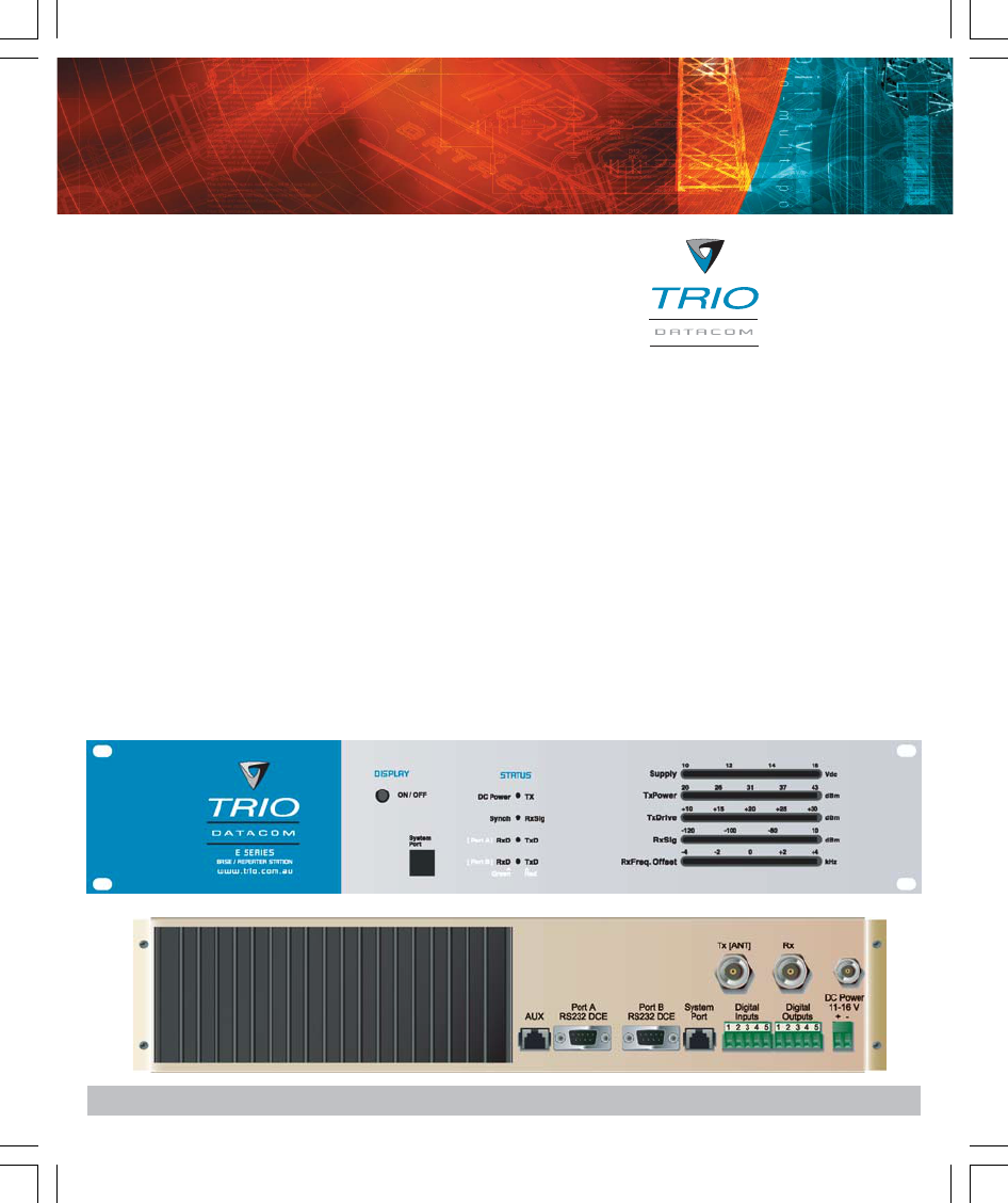
The EB450 Base Station is housed in a 2RU 19” rack
enclosure. The 4 mounting holes on the front panel
should be used to secure the unit to the rack.
The radio should be mounted in a clean and dry location,
protected from water, excessive dust, corrosive fumes,
extremes of temperature and direct sunlight. Please allow
sufficient passive or active ventilation to allow the radio
modem’s heatsink to operate efficiently.
All permanent connections are made at the rear of the
unit. This includes: Power, Antenna, Communications
Ports, Digital I/O and System Port. The front panel has an
additional System Port connection point for easy access.
(see Fig 1 for details)
Fig 2
2.1 Full Duplex Considerations
The EB450 is designed for continuous full duplex
transmission. An automatic thermostatically controlled fan
will operate whenever the internal temperature exceeds
50 degrees Celsius.
2.2 External Duplexer Considerations
The EB450 is normally supplied with seperate Tx and Rx
ports for connection to an external duplexing system.
Depending on the frequency band of operation and the
Tx/Rx frequency split, internal band reject duplexers are
available.
Quick Start Guide - EB450 Base Station 3
3.0 Connecting Antennas and RF
Feeders
The RF antenna system should be installed in
accordance with the manufacturers notes.
The RF connectors used on the EB450 radio are N Type
female connectors. Always use good quality low loss
feeder cable, selected according to the length of the
cable run. Ensure all external connections are
waterproofed using amalgamating tape.
Preset directional antennas in the required direction using
a compass, GPS, or visual alignment and ensure correct
polarisation (vertical or horizontal).
4.0 Communications Ports
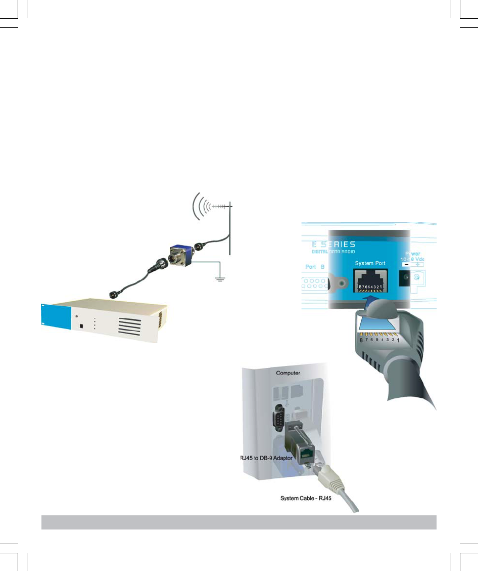
4.1 System Port - RJ45
The System Port (available at the front and rear of the
unit) is a multi-function interface used for:
•Programming / Configuration of the radio
•Remote Diagnostics connections
To access these functions use the standard E Series
System Cable assembly (RJ45 Cable and RJ45 to DB9
Adaptor).
System Port pinout assignments:
Pin 1 System port data out (RS232)
Pin 2 System port data in (RS232)
Pin 3 Not used
Pin 4 Shutdown
Pin 5 Not used
Pin 6 Not used
Pin 7 Ground
Pin 8 External PTT
Special user pinouts:
•Shutdown (Pin 4) - Active low for power save function
•External PTT (Pin 8) - Provides a manual PTT override
facility for enabling the transmitter. For testing this can
be activated by connecting PTT (Pin 8 ) to Gnd (Pin 7).
Fig 3
Fig 4
Fig 5
4Quick Start Guide - EB450 Base Station
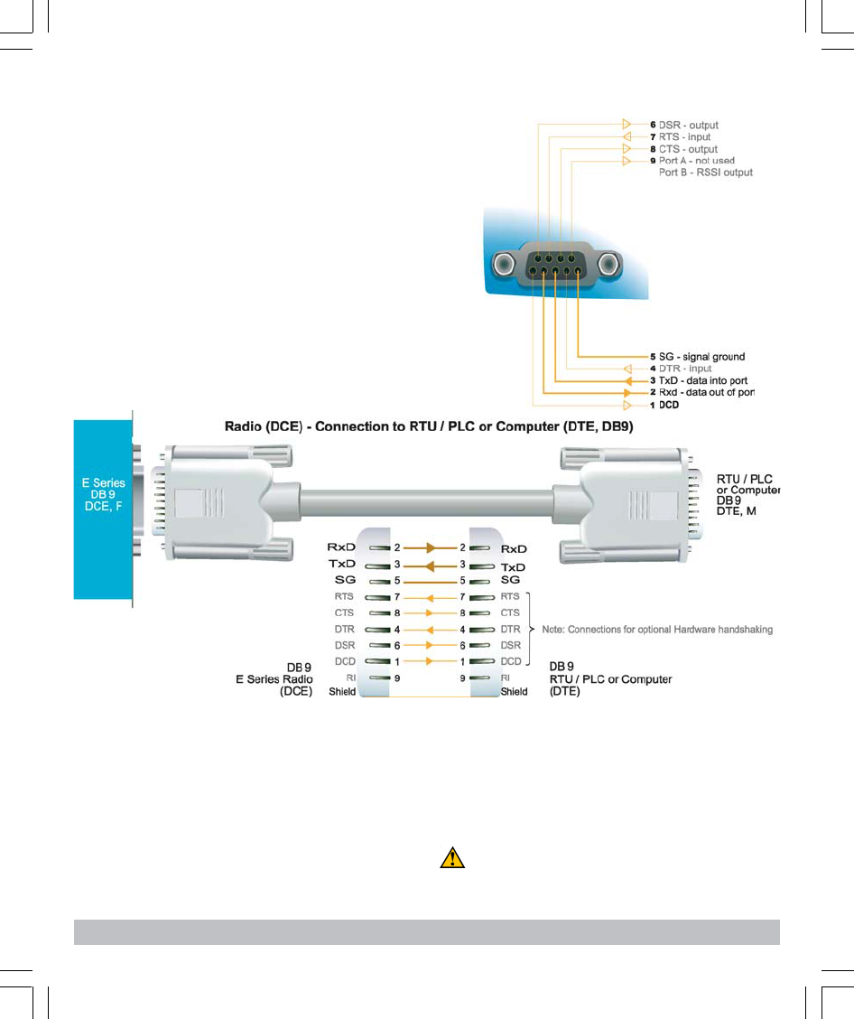
4.2 User Interfaces - Ports A & B
Each user port (A & B) is wired as a RS232 DCE,
configurable for no handshaking (3-wire) interface, or for
hardware or software (X-on/X-off) flow control. In most
systems flow control is not required, in which case only 3
wires need to be connected between the radio and the
application device.
4.3 Typical pins used:
•Pin 2 (RxD) - data output from the radio modem,
• Pin 3 (TxD) - data input to the radio modem,
• Pin 5 (SG) - signal ground.
Refer to User Manual for further details of other cable
configurations.
RS232 Connector Pin outs (DCE)
Port A and B, Female DB9
4.4 Activating the Transmitter
In most systems, the transmitter by default is controlled
automatically by the radio when it has data to transmit.
In some systems, such as full duplex point-to-point links
or full duplex point-to-multipoint base stations, it is
desirable to run the transmitter all the time (hot keyed).
Two mechanisms are provided to do this:
•the radio modem can be configured to transmit
continuously whenever powered, or
•the radio modem can be configured to transmit
whenever an external RTS signal (Pin 7) is applied to
one (or either) user ports. (To simulate an external
RTS input, loop pins 6 to 7).
To operate in these modes, the radio must be configured
via the programming software.
Caution: When the radio is configured to transmit
continuously, ensure an RF load is present BEFORE
applying power to the unit.
Fig 6
Fig 7
Quick Start Guide - EB450 Base Station 5
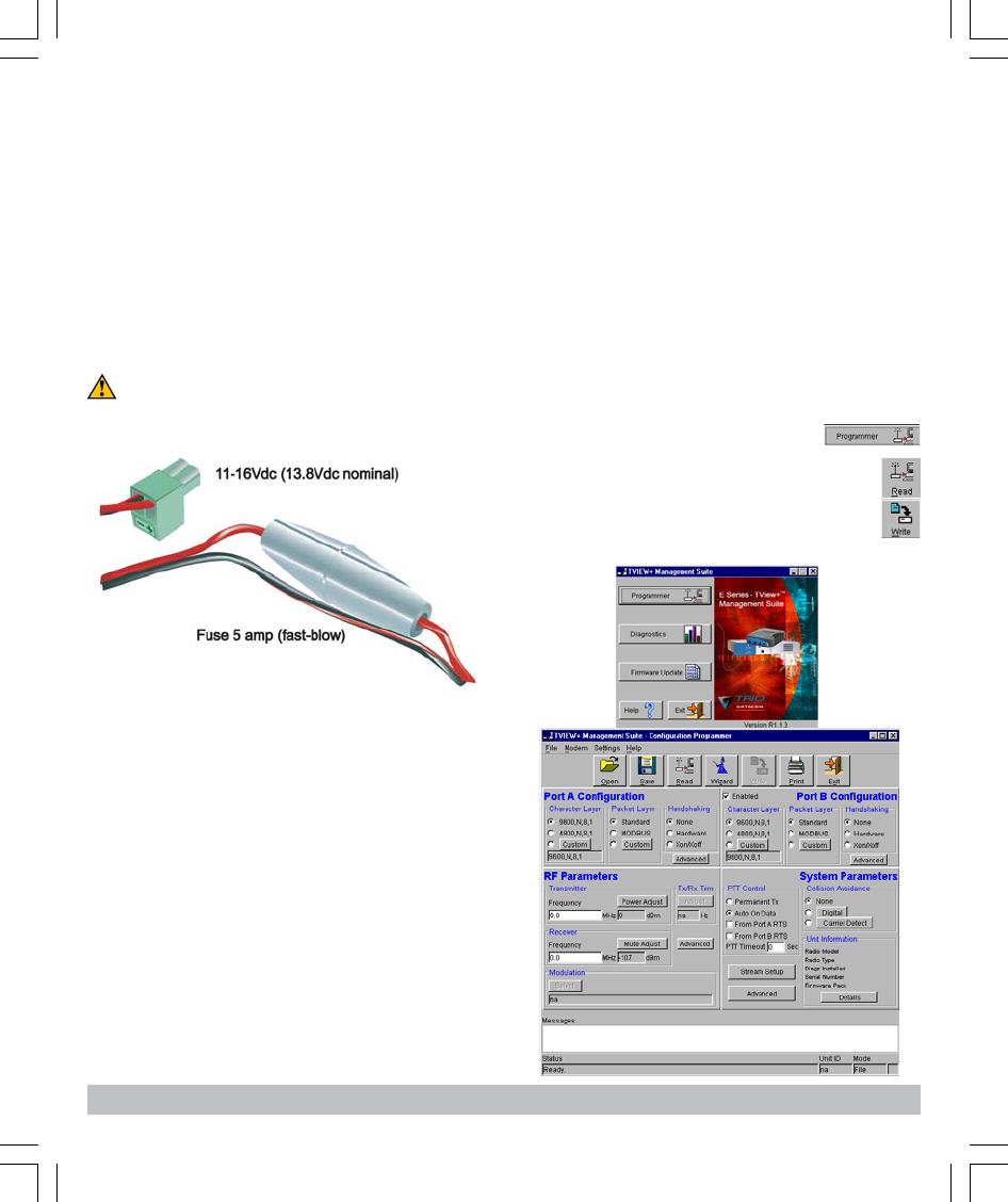
5.0 Power Supply and Protection
(fusing)
The EB450 radio modem is designed and calibrated to
operate from a 13.8Vdc regulated supply, but will operate
from 11-16 volts (filtered) DC.
The current requirement is typically 230mA in receive
mode, and will vary in transmit mode according to RF
output power level (typically 1.3-2.5 amps).
NOTE: Allow an additional 80mA (approx.) for LED bar
graph indicators
Caution: There is NO internal replaceable fuse, and
therefore the radio modem MUST be externally fused with
the fuse holder provided (a 5 amp fast-blow fuse).
6.0 TVIEW+ Management Suite -
Radio Configuration
This TVIEW+ Management Suite allows a number of
features including: Configuration (Local - serial, or
Remote - over-the-air), Remote DiagnosticsFacilities and
Firmware Upgrades.
The configuration wizard can be used to provide Quick
Start generic templates for the types of systems
architecture you wish to employ.
Example: Local configuration session -
1 Attach the programming cable from the PC to the
System Port of the radio (see fig 6 & 7 )
2 Launch TVIEW & Select “Programmer”
3 Select “Read” the radio
4 Change the configuration as required
5 Select “Write” the parameters back to the radio
Refer to User Manual for detailed operation of advanced
features.
Fig 7
The radio is designed to self protect, and will blow the
external fuse if the voltage exceeds 16Vdc, or if reverse
polarity is applied.
The radio modem can also be damaged if there is any
potential difference between the chassis-ground, RS232
signal ground, power (-) input, or antenna coaxial shield.
Before connecting any wiring, ensure all components are
earthed to a common ground point (please pay particular
attention to 24V PLC power systems where converters
are used).
Connect the antenna and RS 232 plugs BEFORE
applying power to the unit.
Lastly, before inserting the power plug, please re-check
that the polarity and voltage on the DC power plug is
correct using a multimeter.
6Quick Start Guide - EB450 Base Station
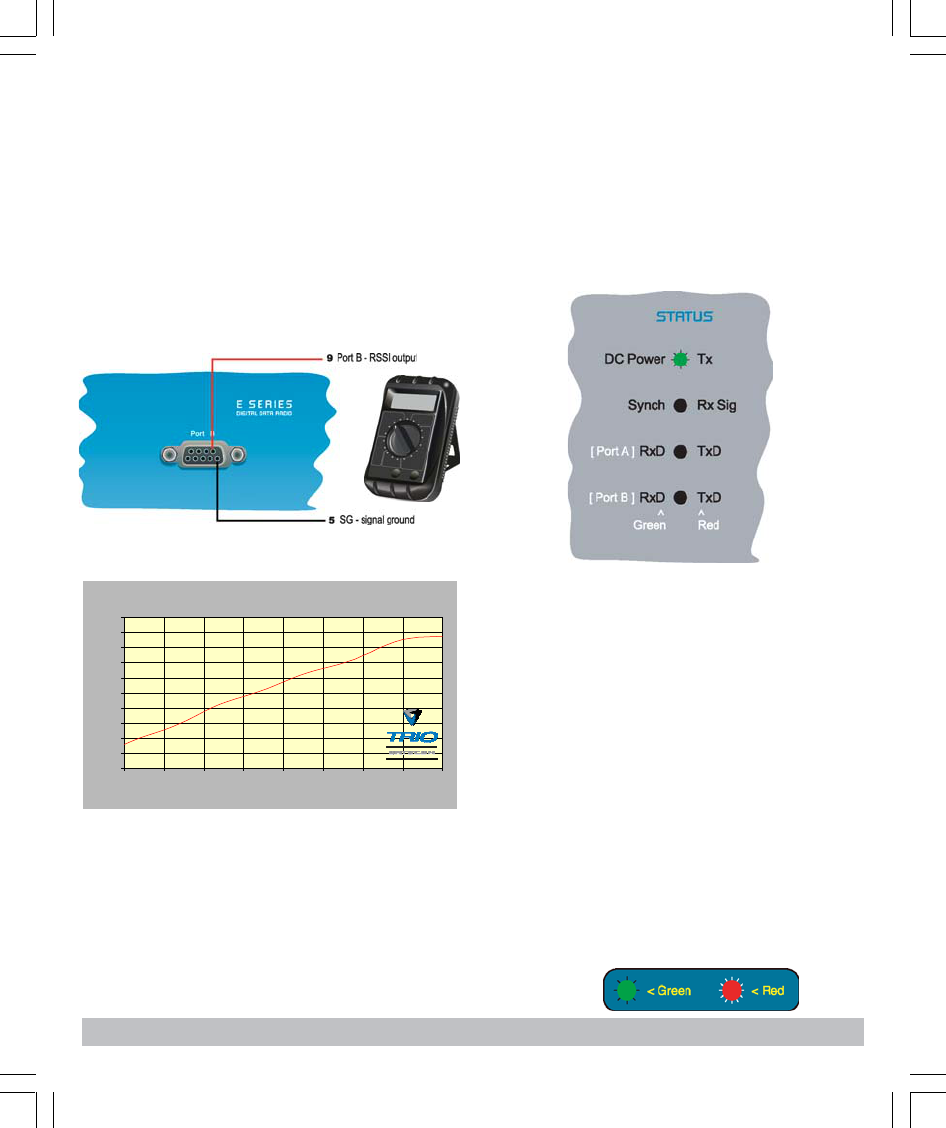
7.0 Optimising the Antenna for
VSWR and best RX signal
Once the unit is operational, it is important to optimise the
antenna tuning.
In the case of a directional antenna, it will be necessary
to align the antenna for the best received signal.
This can be done by using the (0-5Vdc) output on Pin 9
(see fig 9) of Port B to indicate signal strength (RSSI).
This voltage can be converted to dBm using the chart
below.
8.0 LED Indicators & Test outputs
8.1 Radio is Powered
If all the LEDs are off, no power is reaching the radio
modem.
Successful power-up is indicated by the “PWR” LED
indicating a continuous (healthy) GREEN state. Note that
this LED is turned RED when the transmitter is active.
8.2 Voltage Error
If the voltage is too high(>16Vdc) or too low(<10Vdc), an
error message will be displayed on the status LED’s by
illuminating all four (4) LED’s RED.
8.3 Hardware Error
A hardware error is indicated on any one of the status LED’s
by illuminating solid RED. In the case of a hardware error,
the unit must be returned to the service point for repair. In this
case please consult the User Manual for further information
on the error indicated, and record the result with the service
return information.
Analog RSSI Output Characteristics - E Series Data Radio
0
0.5
1
1.5
2
2.5
3
3.5
4
4.5
5
-120 -110 -100 -90 -80 -70 -60 -50 -40
RF Level (dBm)
RSSI (DC Volts)
Fig 9
LED Legend
VSWR testing is achieved by activating the radio’s
transmitter using:
a) An RTS loop as described in Section 4.4, or
b) A system port PTT plug as described in Section 4.1
Refer to the User Manual for further details of VSWR
testing.
Quick Start Guide - EB450 Base Station 7
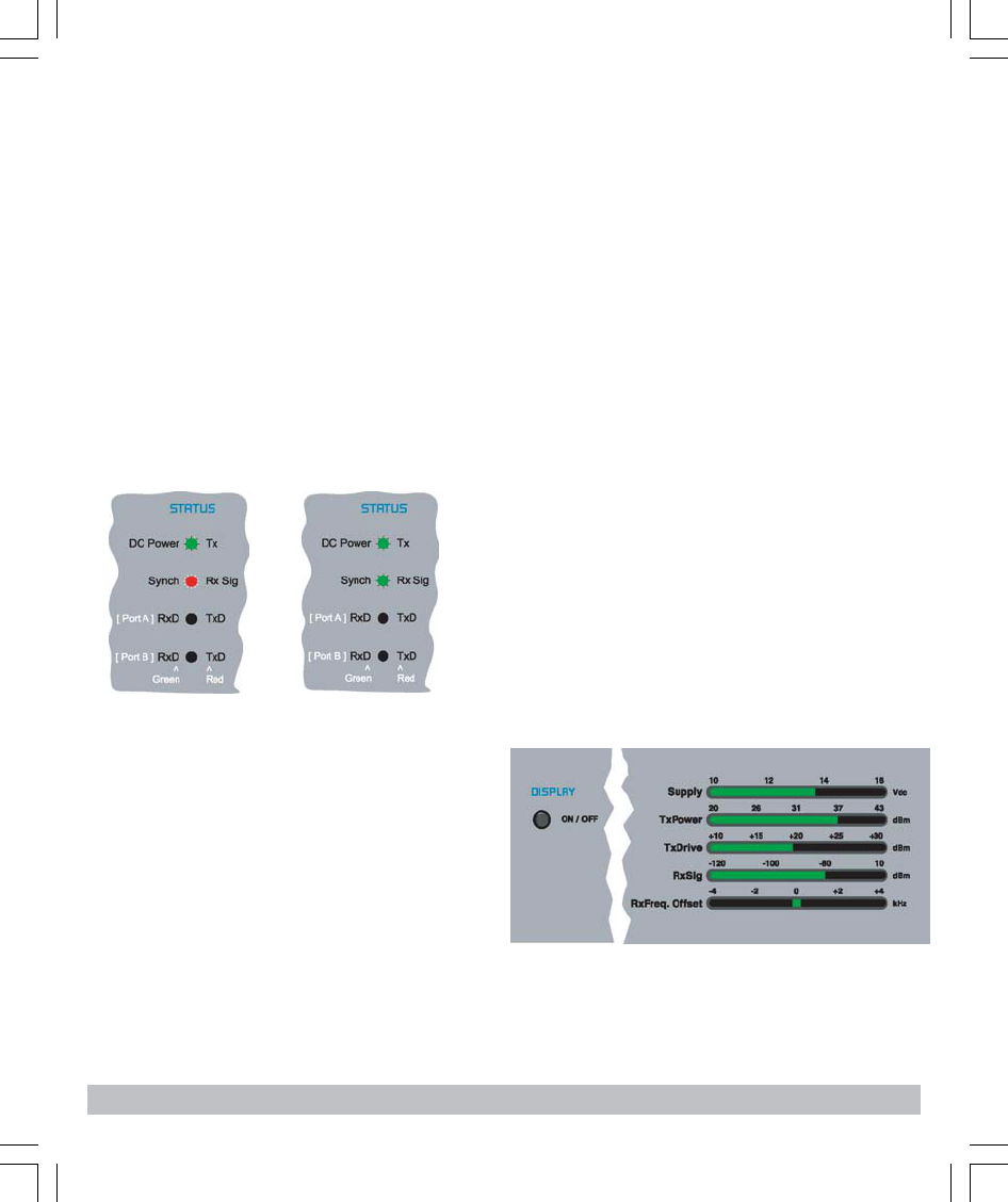
8.4 Received Signal Indicator
The “RX/SYNC” LED indicates the state of the receiver.
If the LED is off, no signal is being received.
A RED indication shows that an RF carrier is being
received, but no data stream can be decoded. This will
breifly happen at the very start of every valid received
transmission or may indicate the presence of
interference, or another user on the channel.
A continuous GREEN indication shows that the modem is
locked and synchronised to the incoming signal, and has
excellent Bit Error Rate (BER). Any losses of
synchronisation (BER errors) are shown as a visible RED
flicker of the LED.
Note: This might only be apparent on a PTMP slave when
only receiving.
8.5 Data Flow “breakout” LEDs
There are also two LEDs to indicate data flow into and
out of the two user ports.
Input data to be transmitted is shown as a RED flash, and
received data to be output to the port is shown as a
GREEN flash.
If data is aternately flowing in and out quickly, then the
indicator appears orange.
DC Supply:
Indicates the supply input voltage at the exciter module.
Typically 13.8Vdc.
Indication: <10Vdc no LED’s on, 10-10.9Vdc LED’s RED,
11-15.6Vdc all LED’s GREEN, >=15.7Vdc last LED RED.
Tx Power:
Indicates forward RF power output as measured at the
TX antenna port. Typically +37dBm.
Indication: <20dBm no LED’s on, 20-40.6dBm (11.5W)
LED’s GREEN, >=40.7dBm last LED RED.
Tx Drive:
Indicates exciter drive level. Typically +20dBm.
Indication: <10dBm no LED’s on, 10.0-25.9dBm LED’s
GREEN, >=26.0dBm last LED RED.
Rx Sig:
Indicates receive signal strength. Typically -85 to -65dBm.
Indication: <-120dBm no LED’s on, -120 to -110.1dBm
LED’s RED, >=-110dBm LED’s GREEN.
RxFreq. Offset:
Indicates offset of receiver AFC - useful in determining
frequency drift. Typically 0kHz.
Indication: Single GREEN LED to indicate current value,
<-3.6kHz or >+3.6kHz LED is RED. No signal, all LED’s
OFF. Note: 5 second peak hold circuitry.
9.1 Test Mode
The Bar Graph indicators have a Test Mode, which cycles
all LED’s for correct operation (before returning to their
normal operation). To activate this mode, simply depress
the ON / OFF button while applying power to the unit.
9.0 Bar Graph Indicators
The bar graph indicators on the front panel provide
variable information regarding the performance of the
Base Station. To enable / disable the bar graph display
depress the Display ON / OFF button. The display will
turn off automatically after 5 minutes.
10.0 Support Options
10.1 Website Information
The Trio DataCom website support page contains links to
e-mail and telephone support, tech notes, manuals,
software updates.
Please go to www.trio.com.au/support.htm.
10.2 E-mail Technical Support
E-mail your questions to support@trio.com.au.
When e-mailing questions to our support staff, make sure
you tell us the exact model number (and serial number if
possible) of the Trio equipment you are working with.
Include as much detail as possible about the situation,
and any tests that you have done which may help us to
better understand the issue. If possible, please include
your telephone contact information should we wish to
further clarify any issues.
10.3 Telephone Technical Support
Telephone support is available at our head office
telephone number Aus: (+61) 3 9775 0505 during Eastern
Australian business hours (9am-5pm).
10.4 Contacting the Service
Department
The Service department may be contacted by e-mail to
service@trio.com.au , or by telephone during Eastern
Australian business hours.
T +613 9775 0505
F +613 9775 0606
E support@trio.com.au
www.trio.com.au
TRIO DATACOM GROUP
41 Aster Avenue
Carrum Downs VIC
Australia 3201
Information subject to change without notice.
© Copyright 2002 Trio DataCom Pty Ltd. All rights reserved.
Innovative and sophisticated
digital communications
designs products and solutions
Issue 3: May 2003