Sepura SRG3500XB TETRA Mobile/Gateway Terminal User Manual SPR DOC 00117 8
Sepura plc TETRA Mobile/Gateway Terminal SPR DOC 00117 8
UserManual.wiki
>
Sepura
>
SRG3500XB User Manual
>
Installation guide
Contents
1.
Product guide
2.
Mobile gateway accessories
3.
SRG3500 Gateway repeater specification
4.
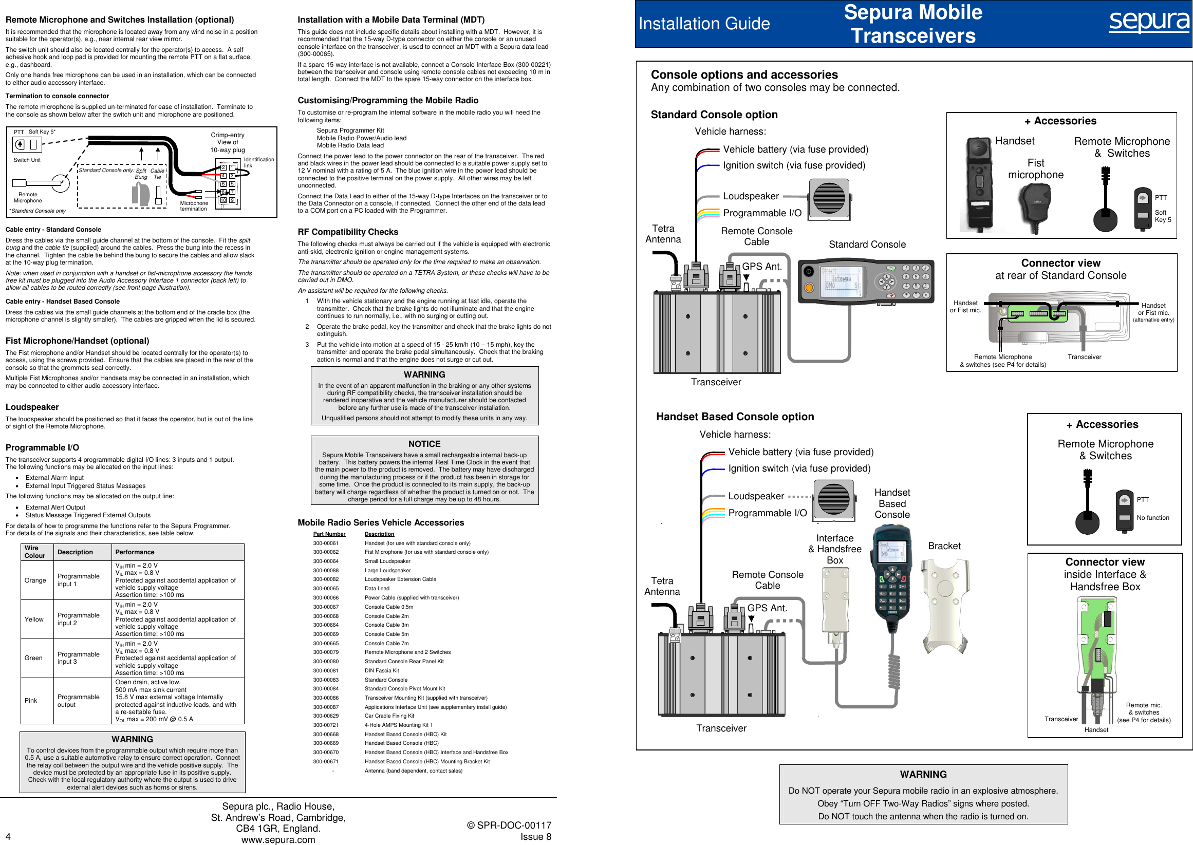
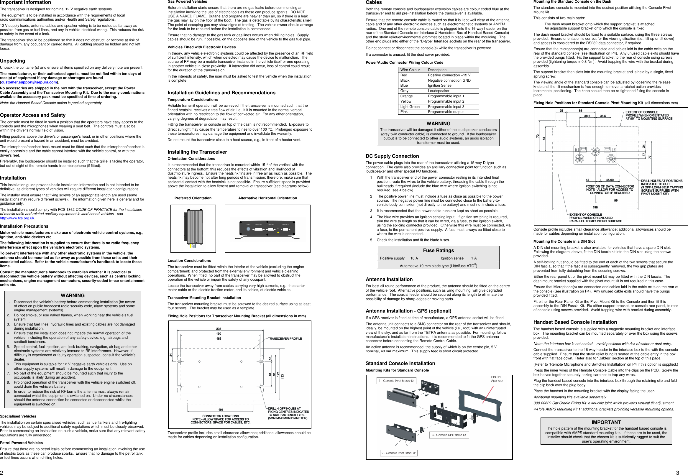
Installation guide
5.
Quick reference guide
Installation guide
Navigation menu
Upload a User Manual
Namespaces
Wiki Guide
HTML
PDF
Info
Views
User Manual
Discussion / Help
Navigation