Sepura SRG3500XB TETRA Mobile/Gateway Terminal User Manual Mobile Gateway
Sepura plc TETRA Mobile/Gateway Terminal Mobile Gateway
Sepura >
Contents
- 1. Product guide
- 2. Mobile gateway accessories
- 3. SRG3500 Gateway repeater specification
- 4. Installation guide
- 5. Quick reference guide
Mobile gateway accessories

![SB-P-06-4066 sepura Mobile & Gateway Accessory i/f specification 30th July 2012 Page 6 of 39 Issue 7c © Sepura plc 2011 ISSUE HISTORY Version Date Change Version 1 1st June 2006 Supersedes SB-P-05-4042 Version 2 24th July 2006 Added declaration of conformity statement. Added abbreviations table. Clarified difference between Mk1 and Mk2 AIU‘s. Added cable form details. Version 3 22nd Sept 2006 Clarified data interface = PEI port Corrected AIU Mk1 and Mk2 contents re audio accessory support Clarified MIC and EAR on RCI port no longer supported AIU Mk1 superseded by AIU Mk2 Added Input freq spec and levels for GPS antenna Version 4 19th Jan 2007 3679 parameter details added SRM/G2 and 3 digital I/O capability clarification. Version 5 17th April 2007 Added reverse battery polarity comment and note re digital input resistance. Corrected block diagram GPS connector. Added GPS LNA gain requirement Version 6 17th Feb 2009 Incorporates V9 changes (AIS Issue 7 and 8 of the development document) Version 6a 6th May 2009 Added [ITU-T V.24] and [ITU-T V.28] RS232 serial data compliant Version 6b 13th Aug 2010 Added comment to section 6 regarding sidetone being present for all accessories Issue 7 15th Sept 2010 Corrected formatting issues found in issue 6b Issue 7a 10th Jan 2011 Corrected hyperlink error on page 13 & 14. Added reference for SCC AIS Issue 7b 20th Jul 2011 Further tidy up of formatting Issue 7c 30th Jul 2012 Corrected references to digital i/o on console (page10)](https://usermanual.wiki/Sepura/SRG3500XB.Mobile-gateway-accessories/User-Guide-1756135-Page-6.png)
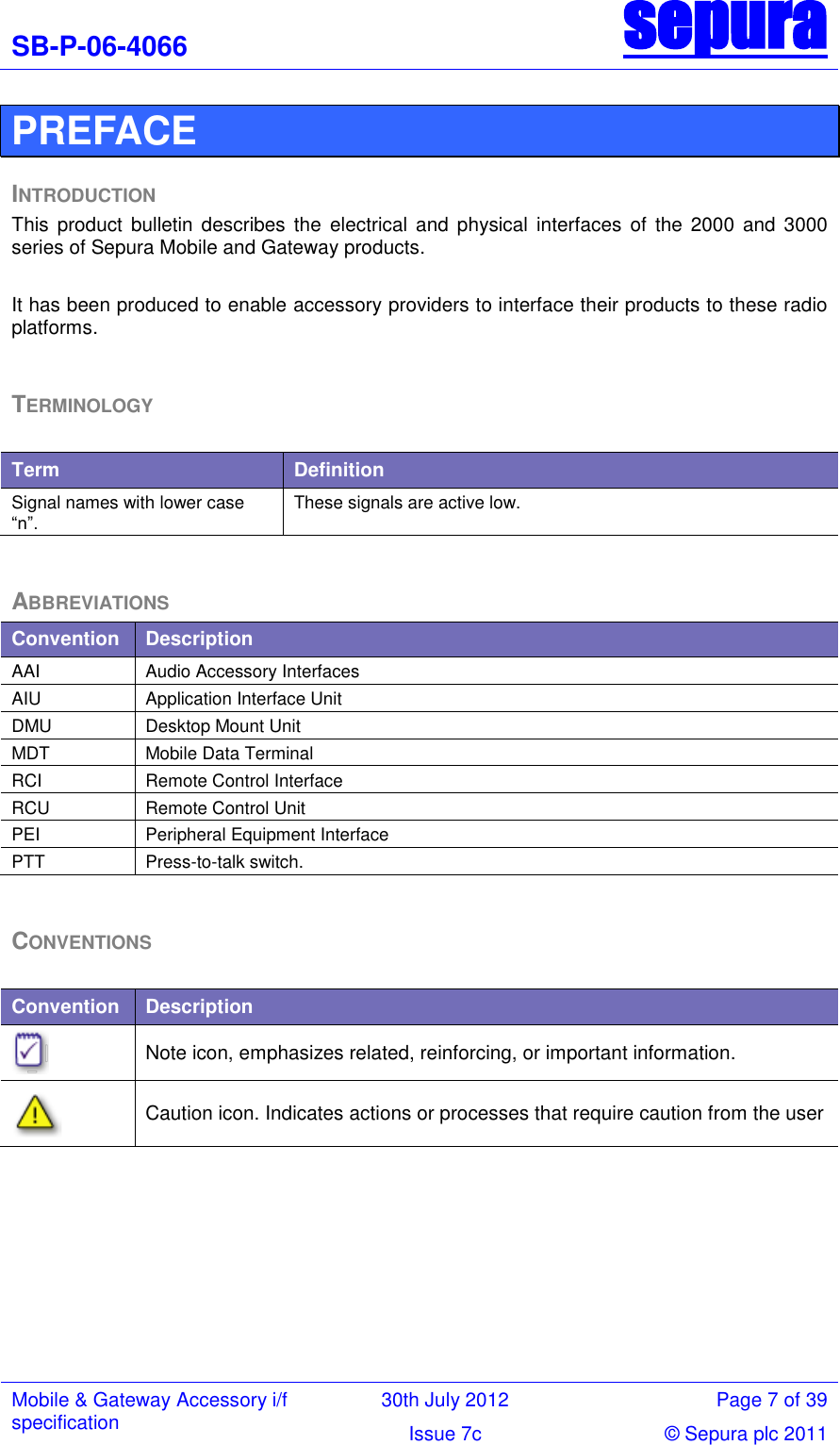
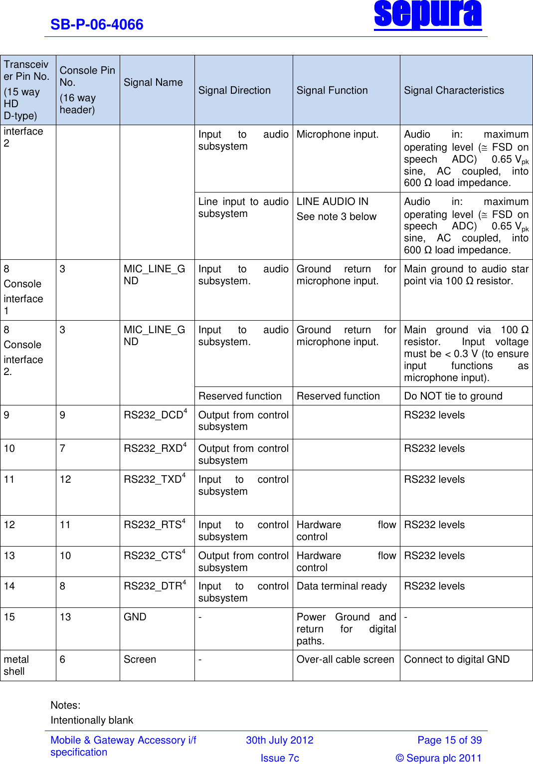
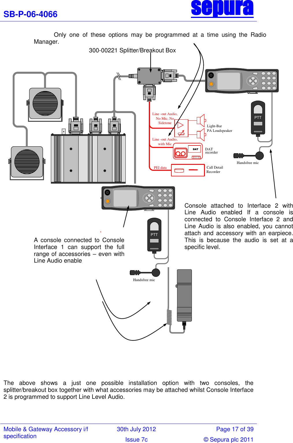
![SB-P-06-4066 sepura Mobile & Gateway Accessory i/f specification 30th July 2012 Page 16 of 39 Issue 7c © Sepura plc 2011 The mechanism to switch the transceiver off from the console uses a Sepura proprietary message sent over the console control data interface (pins 1 and 2). Line level audio is supported on the 380-430MHz band transceiver with V9 software (or latter) plus the appropriate Feature License Code (part number 600-00033) installed via Radio Manager. 380-430MHz radios can be identified by having ―W‖ as the fifth character of the nineteen character hardware code. RS232 interface is [ITU-T V.24] & [ITU-T V.28] Compliant LINE LEVEL AUDIO SUPPORT The following table is a subset of the table in 6.4 showing only the relevant connections for Line Level audio: Line Level Audio IN (pins 7 and 8 on Console Interface 2) and Line Level Audio OUT (pins 5 and 6 on Console Interface 2) Transceiver Pin No. (15 way HD D-type) Console Pin No. (16 way header) Signal Name Signal Direction Signal Function Signal Characteristics Line Audio OUT pair 5 Console interface 2 2 LS_LINE_13 Line output from audio subsystem. LINE AUDIO OUT See note 3 above Maximum output ( peak DAC output) 1.25 Vpk sine, a.c. coupled, into 600 Ω load. 6 Console interface 2 4 LS_LINE_2 Output from audio subsystem Ground return for audio line output. Ground to audio star point Line Audio IN pair 7 Console interface 2 1 MIC_LINE_SIG Line input to audio subsystem LINE AUDIO IN See note 3 above Audio in: maximum operating level ( FSD on speech ADC) 0.65 Vpk sine, AC coupled, into 600 Ω load impedance. 8 Console interface 2. 3 MIC_LINE_GND Input to audio subsystem. Ground return for microphone input. Main ground via 100 Ω resistor. Input voltage < 0.3 V (to ensure input functions as microphone input). metal shell 6 Screen - Over-all cable screen Connect to digital GND It is expected that a 3rd party will construct a bespoke cable to bring the above connections into use. A splitter/breakout box (300-00221) is available to allow both connection of a Console and facilitate simple connection by a third party cable (see over leaf).](https://usermanual.wiki/Sepura/SRG3500XB.Mobile-gateway-accessories/User-Guide-1756135-Page-16.png)