Sepura SRG3500XB TETRA Mobile/Gateway Terminal User Manual Mobile Gateway
Sepura plc TETRA Mobile/Gateway Terminal Mobile Gateway
Sepura >
Contents
- 1. Product guide
- 2. Mobile gateway accessories
- 3. SRG3500 Gateway repeater specification
- 4. Installation guide
- 5. Quick reference guide
Mobile gateway accessories

sepura
Mobile & Gateway
Accessory i/f specification
SB-P-06-4066
PRODUCT BULLETIN
© SEPURA PLC 2011

SB-P-06-4066
sepura
Mobile & Gateway Accessory i/f
specification
30th July 2012
Page 2 of 39
Issue 7c
© Sepura plc 2011
Contents
LEGAL RESPONSIBILITIES........................................................................... 5
ISSUE HISTORY ............................................................................................. 6
PREFACE ........................................................................................................ 7
Introduction .............................................................................................................................. 7
Terminology ............................................................................................................................. 7
Abbreviations ........................................................................................................................... 7
Conventions ............................................................................................................................. 7
DECLARATION OF CONFORMITY ................................................................ 8
INTERFACE OVERVIEW .............................................................................. 10
Transceiver ............................................................................................................................. 10
Console ................................................................................................................................... 10
AIU Mk1 ................................................................................................................................... 11
AIU Mk2. .................................................................................................................................. 11
Example interconnect block diagram .................................................................................. 12
CONSOLE INTERFACE ................................................................................ 13
Connector details .................................................................................................................. 13
Transceiver connector. ......................................................................................................... 13
Console/AIU connector ......................................................................................................... 13
Signal details .......................................................................................................................... 14
Line Level Audio Support ..................................................................................................... 16
POWER SUPPLY INTERFACE ..................................................................... 19
Connector details .................................................................................................................. 19

SB-P-06-4066
sepura
Mobile & Gateway Accessory i/f
specification
30th July 2012
Page 3 of 39
Issue 7c
© Sepura plc 2011
Signal details .......................................................................................................................... 19
Speaker configurations ......................................................................................................... 21
AUDIO ACCESSORY INTERFACE (AAI) ..................................................... 22
Connector details .................................................................................................................. 22
Signal details .......................................................................................................................... 22
Audio Accessory Identity Table ........................................................................................... 24
Accessory Keys Table .......................................................................................................... 24
Audio gain .............................................................................................................................. 25
AIU MK 1 Jack Connectors ................................................................................................... 26
Connector Details .................................................................................................................. 26
Jack Signals ........................................................................................................................... 26
AIU MK 2 Jack Connectors ................................................................................................... 27
AAI2 – via jack connector ..................................................................................................... 27
RCI CONNECTIONS ..................................................................................... 29
Connector Details .................................................................................................................. 29
Signal details .......................................................................................................................... 29
DESK MOUNT UNIT CONNECTORS ........................................................... 31
Desk Microphone/Headset Connector................................................................................. 31
Connector Details .................................................................................................................. 31
Signals .................................................................................................................................... 31
Foot Switch Connector ......................................................................................................... 31
Connector Details .................................................................................................................. 31
Signals .................................................................................................................................... 32
Loudspeaker Connector ....................................................................................................... 32
DATA CONNECTOR INTERFACE ............................................................... 33
Connector details .................................................................................................................. 33

SB-P-06-4066
sepura
Mobile & Gateway Accessory i/f
specification
30th July 2012
Page 4 of 39
Issue 7c
© Sepura plc 2011
Signal details .......................................................................................................................... 33
ANTENNA’S .................................................................................................. 35
Connector details .................................................................................................................. 35
Signal details .......................................................................................................................... 35
GPS ANTENNA ............................................................................................. 36
Connector details .................................................................................................................. 36
Signal details .......................................................................................................................... 36
CONSOLE AND AIU CABLE SPECIFCATION ............................................ 37
Cableform Mechanical Details .............................................................................................. 37
Cable form Grommet ............................................................................................................. 38
NOTICE ......................................................................................................... 39
Contact Details ....................................................................................................................... 39

SB-P-06-4066
sepura
Mobile & Gateway Accessory i/f
specification
30th July 2012
Page 5 of 39
Issue 7c
© Sepura plc 2011
LEGAL RESPONSIBILITIES
The information in this document is subject to change without notice and describes only the
product defined in this document. This document is intended for the use of Sepura plc‘s
customers and/or other parties only for the purposes of the agreement or arrangement under
which this document is submitted, and no part of it may be reproduced or transmitted in any
form or means without the prior written permission of Sepura plc.
The document has been prepared to be used by professional and properly trained personnel,
and the customer and/or other party assumes full responsibility when using it. Sepura plc
welcomes customer and/or other party comments as part of the process of continuous
development and improvement of the documentation.
The information or statements given in this document concerning the suitability, capacity, or
performance of the mentioned hardware or software products cannot be considered binding
but shall be defined in the agreement or arrangement made between Sepura Plc and the
customer and/or other party.
However, Sepura plc has made all reasonable efforts to ensure that the instructions contained
in the document are adequate and free of material errors and omissions. Sepura plc will, if
necessary, explain issues which may not be covered by this document.
Sepura plc‘s liability for any errors in this document is limited to the documentary correction of
errors. Sepura plc will not be responsible in any event for errors in this document or for any
damages, incidental or consequential, (including monetary losses), that might arise from the
use of this document or the information in it.
This document and the product it describes are considered protected by copyright according
to the applicable laws.
Other product names mentioned in this document may be trademarks of their respective
companies, and they are mentioned for identification purposes only.
SB-P-06-4066
sepura
Mobile & Gateway Accessory i/f
specification
30th July 2012
Page 6 of 39
Issue 7c
© Sepura plc 2011
ISSUE HISTORY
Version
Date
Change
Version 1
1st June 2006
Supersedes SB-P-05-4042
Version 2
24th July 2006
Added declaration of conformity statement.
Added abbreviations table.
Clarified difference between Mk1 and Mk2 AIU‘s.
Added cable form details.
Version 3
22nd Sept 2006
Clarified data interface = PEI port
Corrected AIU Mk1 and Mk2 contents re audio accessory
support
Clarified MIC and EAR on RCI port no longer supported
AIU Mk1 superseded by AIU Mk2
Added Input freq spec and levels for GPS antenna
Version 4
19th Jan 2007
3679 parameter details added
SRM/G2 and 3 digital I/O capability clarification.
Version 5
17th April 2007
Added reverse battery polarity comment and note re digital
input resistance.
Corrected block diagram GPS connector.
Added GPS LNA gain requirement
Version 6
17th Feb 2009
Incorporates V9 changes (AIS Issue 7 and 8 of the
development document)
Version 6a
6th May 2009
Added [ITU-T V.24] and [ITU-T V.28] RS232 serial data
compliant
Version 6b
13th Aug 2010
Added comment to section 6 regarding sidetone being
present for all accessories
Issue 7
15th Sept 2010
Corrected formatting issues found in issue 6b
Issue 7a
10th Jan 2011
Corrected hyperlink error on page 13 & 14. Added reference
for SCC AIS
Issue 7b
20th Jul 2011
Further tidy up of formatting
Issue 7c
30th Jul 2012
Corrected references to digital i/o on console (page10)
SB-P-06-4066
sepura
Mobile & Gateway Accessory i/f
specification
30th July 2012
Page 7 of 39
Issue 7c
© Sepura plc 2011
PREFACE
INTRODUCTION
This product bulletin describes the electrical and physical interfaces of the 2000 and 3000
series of Sepura Mobile and Gateway products.
It has been produced to enable accessory providers to interface their products to these radio
platforms.
TERMINOLOGY
Term
Definition
Signal names with lower case
―n‖.
These signals are active low.
ABBREVIATIONS
Convention
Description
AAI
Audio Accessory Interfaces
AIU
Application Interface Unit
DMU
Desktop Mount Unit
MDT
Mobile Data Terminal
RCI
Remote Control Interface
RCU
Remote Control Unit
PEI
Peripheral Equipment Interface
PTT
Press-to-talk switch.
CONVENTIONS
Convention
Description
Note icon, emphasizes related, reinforcing, or important information.
Caution icon. Indicates actions or processes that require caution from the user

SB-P-06-4066
sepura
Mobile & Gateway Accessory i/f
specification
30th July 2012
Page 8 of 39
Issue 7c
© Sepura plc 2011
DECLARATION OF CONFORMITY
Sepura mobile terminals and approved accessories are compliant with the essential
requirements of the 1999/05/EC Radio and Telecommunications Terminal Equipment
(R&TTE) Directive. The mobile variants and accessories are specified in the Declaration of
Conformity number DC/C 02001-3.
A copy of the declaration is available from Sepura on request.
As such, Sepura mobile terminals are compliant with the following mandatory specifications:
Safety to relevant parts of EN 60950 (Safety of Information Technology Equipment). This
includes the Low Voltage Directive (LVD);
Electromagnetic Compatibility (EMC) to relevant parts of EN 301 489 (Electromagnetic
Compatibility & Radio Spectrum Matters);
TETRA air interface to EN 303 035 (Terrestrial Trunked Radio (TETRA); Harmonized EN for
TETRA equipment covering essential requirements under article 3.2 of the R&TTE Directive);
In addition, Sepura mobile terminals and Third Party Accessory must also maintain
conformance in the following areas:
Dust & moisture protection to IP54 or greater to meet the needs of the user environment and
the relevant parts of ETS 300-019; CEN1789:2000
Protection against Acoustic Shock to relevant parts of ITU P.360. Sepura mobile terminals
comply with the maximum audio levels specified for Longer Duration disturbances.
The performance of the mobile must not be compromised by the r.f. field generated by the
mobile interfering with the accessory (different versions of Sepura mobile terminals operate
over frequencies within the range 350 MHz to 900 MHz and generate signals complying with
TETRA standards).
For example no audio interference should occur when a TETRA portable transmitting at 1 W
r.f. power, at frequencies between 300 MHz and 900 MHz, is held within 1cm of the
accessory.
The product shall not degrade the performance of a SRM/G 3500/3900 installation when
tested to TETRA EMC spec. EN 301489-1&18 V1.6.1 (2005-09) Including Annex B.
The combination of the accessory and the mobile must be ―fit for purpose‖. The use of an
accessory must not make the mobile difficult or awkward to use, or in any way degrade its
performance.
It is most important that any accessory designed for use with Sepura mobile
terminals does not affect any of the current approvals

SB-P-06-4066
sepura
Mobile & Gateway Accessory i/f
specification
30th July 2012
Page 9 of 39
Issue 7c
© Sepura plc 2011
Sepura requires the designer/manufacturer to:
Allow Sepura to review, and comment on, the ―Test Plan‖ — this document will
describe the tests to be performed by, or on behalf of, the Third Party accessory
designer/manufacturer to confirm continued compliance with the above specifications,
Provide Sepura with a ―technical file”, which shall contain design details and results of
tests undertaken and the appropriate Declaration of Conformity. The information must
be approved by Sepura prior to the Third Party supplying the Accessory to
customers.
Sepura must be notified of any amendment to the approved Accessory which could
affect the continued conformance. In the event that there is a problem, perceived or
real, with the interaction of Sepura mobile terminals and the supplied Third Party
Accessory, the Third Party must make available to Sepura documentary evidence of
relevant test results.
The “technical file” must be approved by Sepura prior to the Third Party supplying
the Accessory to customers.

SB-P-06-4066
sepura
Mobile & Gateway Accessory i/f
specification
30th July 2012
Page 10 of 39
Issue 7c
© Sepura plc 2011
INTERFACE OVERVIEW
The Mobile and Gateway products are available as a one, two or three unit solution
supporting a mix of up to two Consoles or Application Interface Units (AIU) plus the
transceiver, allowing the radios to be used in many different applications and support up to 4
audio accessories such as handsets, fist microphones and headsets.
TRANSCEIVER
The SRM and SRG series of transceivers support:
2 off Console Interfaces - each can support a Console, an AIU, or an external data
application connected via a Sepura data lead. Any combinations of units on the two
Console Interfaces are possible. The Console interface is also used to customise and
program the unit via Radio Manager.
1 off Power interface providing connection for the battery, ignition sense line and also
the transceivers speaker.
3 digital inputs and 1 digital output on the power interface connector
1 off RF connector for the Tetra antenna.
GPS connector (optional).
The SRM2000, SRG2000 and SRM3500 series of transceivers are no longer
available; they have been superseded by the SRG3500/SRG3900 transceiver.
CONSOLE
Each Console provides:
2 off AAI ports allowing connection of two audio accessories. Each AAI supports
optional hook signalling, PTT input and up to 6 accessory keys.
1 off data interface with RS232 PEI port allows connection to an external data
application via a Sepura Data Lead. The interface is also used to customise and
program the unit via Radio Manager.
The extra 3 digital inputs and 1 digital output available on the transceiver power
interface connector are not available from the console.
For details of the SCC accessories interface, see document MOD-10-1253 for further
information

SB-P-06-4066
sepura
Mobile & Gateway Accessory i/f
specification
30th July 2012
Page 11 of 39
Issue 7c
© Sepura plc 2011
AIU MK1
The AIU Mk1 provides:
2 off AAI ports allow connection of two audio accessories. Each AAI supports
optional hook signalling, PTT input and up to 6 accessory keys. AAI2 audio
connections are also mirrored to the Jack sockets, allowing flexibility in the
connection of audio accessories.
1 off data interface with RS232 PEI port allowing connection of an external data
application via a Sepura Data Lead. The interface is also used to customise and
program the unit via Radio Manager.
3 digital inputs.
1 digital output.
The AIU Mk1 (part number 300-00087) is no longer available, it has been
superseded by the AIU Mk2 (part number 300-00217).
AIU MK2.
The AIU Mk2 supersedes the MK1 device and provides:
1 off AAI allowing connection of one audio accessory. The AAI1 supports optional
hook signalling, PTT input and up to 6 accessory keys.
AAI2 is only presented on a Jack socket, allowing connection of a second audio
accessory.
1 off RCI port enabling control of the transceiver via an RCU such as the Sepura 300-
00164.
1 off data interface with RS232 PEI port allowing connection of an external data
application via a Sepura Data Lead. The interface is also used to customise and
program the unit via Radio Manager.
3 digital inputs.
1 digital output.
SB-P-06-4066
sepura
Mobile & Gateway Accessory i/f
specification
30th July 2012
Page 12 of 39
Issue 7c
© Sepura plc 2011
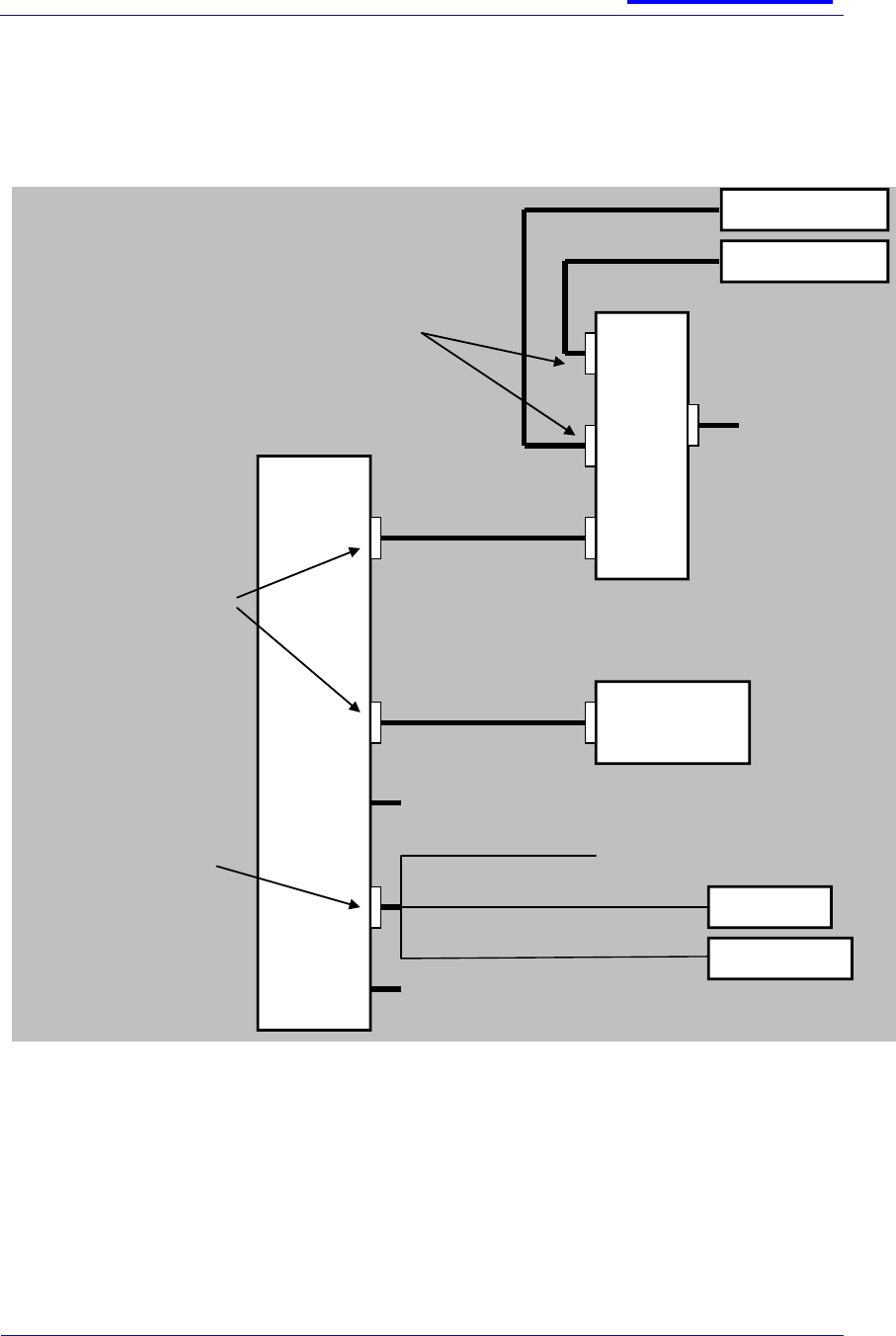
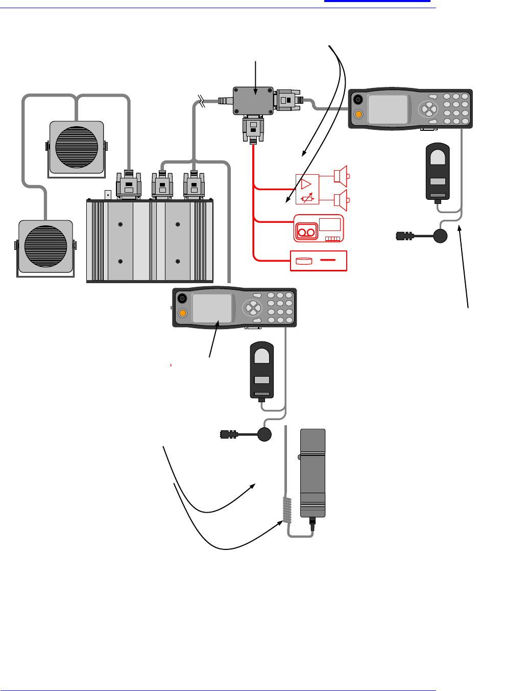
EXAMPLE INTERCONNECT BLOCK DIAGRAM
The diagram shows just one of many possible solutions and highlights the flexibility of the
Sepura product.
Console Interface
(15 way HD Type)
Proprietary console interface
signaling
Standard RS232 PEI Port for
connection of third party
equipment and transceiver
programming.
Microphone line audio
Earpiece line audio
Console power
On/Off Control
Ground
Data Interface Connector
(15 Way HD Type)
Standard RS232 PEI
Port for connection of
third party equipment
and transceiver
programming
4 Programmable I/O
(AIU only)
Console
or
AIU Mk1
Audio Accessory Interface (10 way Hirose)
Microphone input
Earpiece output
Hooking input
PTT input
Accessory soft key input
Accessory identifier input
Ground
Power Supply Interface
(15 way D Type)
Supply input and ground
reference
Ignition sense input
Loudspeaker Output
4 Programmable I/O
Antenna Connector
BNC
Audio Accessory 2
Audio Accessory 1
MDT or
Programmer
Battery/
Ignition detect
Digital I/O
Loudspeaker
Data Lead
15 Way HD Type to
9 Way D Type
Console to Transceiver Cable
15 way HD type to 16 way Hirose
GPS Connector (option)
SMC
Transceiver
SB-P-06-4066
sepura
Mobile & Gateway Accessory i/f
specification
30th July 2012
Page 13 of 39
Issue 7c
© Sepura plc 2011
CONSOLE INTERFACE
There are a number of Console Interfaces:
2 off on the Transceiver designated ‗Interface1‘ and ‗Interface 2‘.
1 off on the Console used to connect the Console back to the transceiver via ‗Interface1‘ or
‗Interface 2‘.
1 off on AIU Mk1 and 2 designated ‗TRX‘ used to connect the Console back to the transceiver
via ‗Interface1‘ and ‗Interface 2‘.
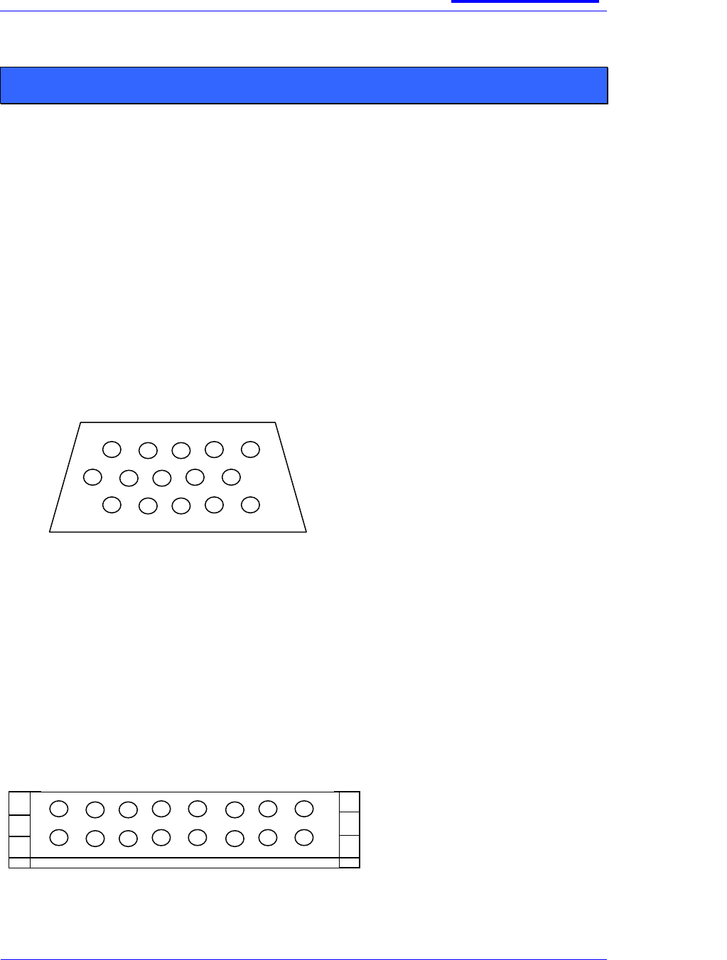
CONNECTOR DETAILS
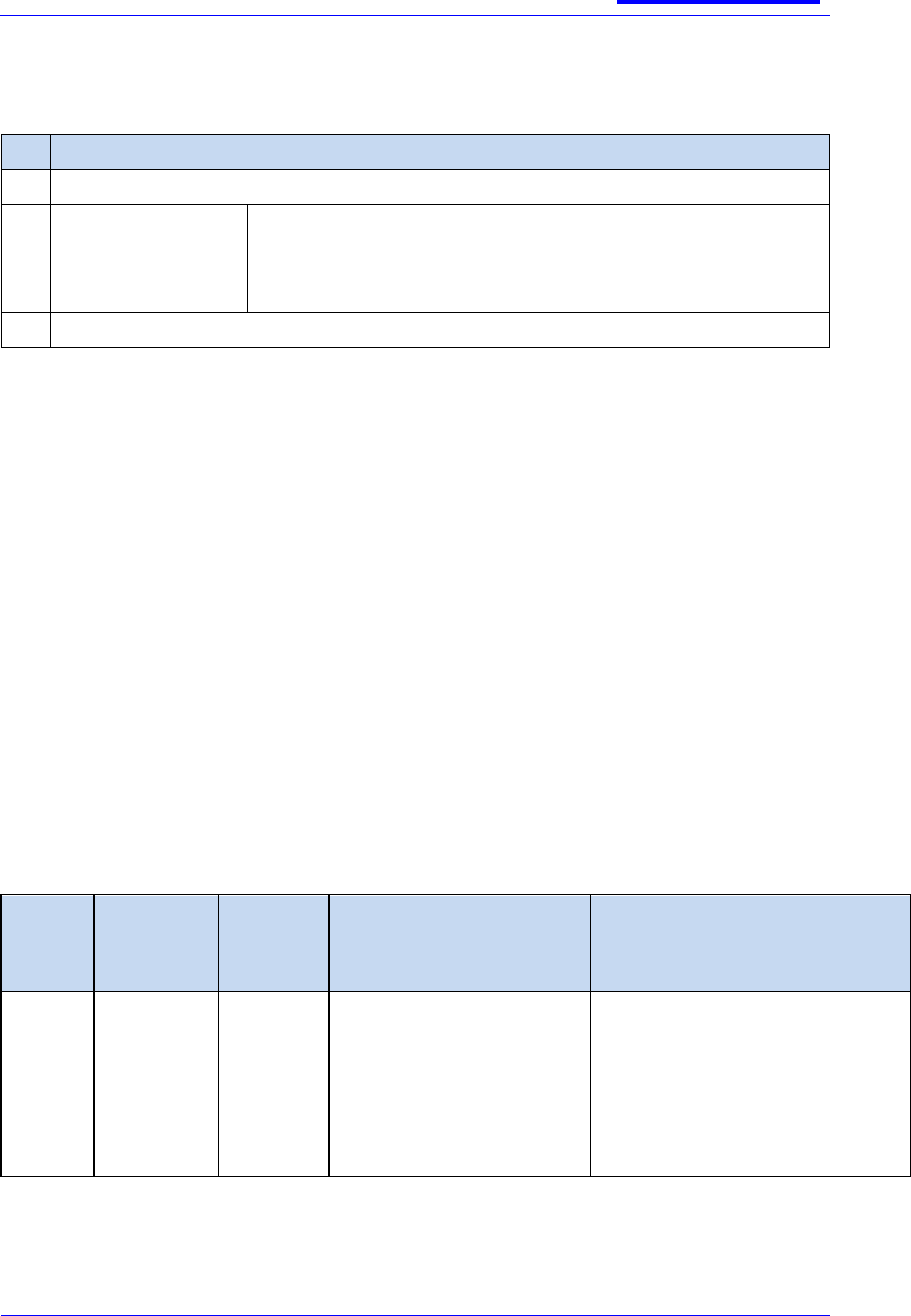
TRANSCEIVER CONNECTOR.
Connector Type: 15 way high density D type female
Connector viewed from the rear of the Transceiver
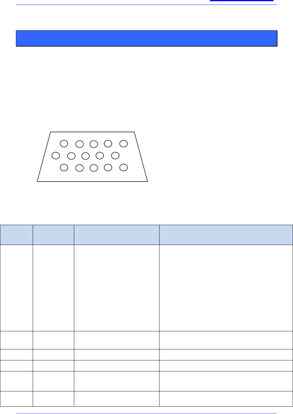
CONSOLE/AIU CONNECTOR
Connector Type: Hirose 16 way male header,
Sepura part number 3513 999 99318
Mating plug: Hirose number DF11-16DS-2C
11 12 13 14 15
1 2 3 4 5
6 7 8 9 10
1 3 5 7 9 11 13 15
2 4 6 8 10 12 14 16
Connector viewed from the rear of the Console.

SB-P-06-4066
sepura
Mobile & Gateway Accessory i/f
specification
30th July 2012
Page 14 of 39
Issue 7c
© Sepura plc 2011
SIGNAL DETAILS
Transceiv
er Pin No.
(15 way
HD
D-type)
Console Pin
No.
(16 way
header)
Signal Name
Signal Direction
Signal Function
Signal Characteristics
1
14
CONSOLE_T
XD
Input to control
subsystem
Control data from the
console.
RS232 levels
2
16
CONSOLE_R
XD
Output from
control subsystem
Control data to the
console.
RS232 levels
3
5
PWR_ON
Output from
console subsystem
Switch signal to turn
transceiver on2.
Low going edge triggered.
Pull to 0 V to switch-on.
(Pull up to un-switched
12 V rail in the
transceiver.)
Assertion time: 10 ms
4
15
POWER_OUT
Output from PSU
subsystem
Power supply to
console
13V nominal supply,
enabled internally to the
transceiver. Includes over
current/temperature
protection.
Rated for 280 mA nominal
load 400 mA max.
5
Console
interface
1
2
LS_LINE_13
Output from audio
subsystem
Audio line output to
console.
Maximum output ( peak
DAC output) 1.25 Vpk sine,
a.c. coupled,
into 600 Ω load.
5
Console
interface
2
2
LS_LINE_13
Output from audio
subsystem
Audio line output to
console.
Maximum output ( peak
DAC output) 1.25 Vpk sine,
a.c. coupled,
into 600 Ω load.
Line output from
audio subsystem.
LINE AUDIO OUT
See note 3 below
Maximum output ( peak
DAC output) 1.25 Vpk sine,
a.c. coupled,
into 600 Ω load.
6
4
LS_LINE_2
Output from audio
subsystem
Ground return for
audio line output.
Ground to audio star point
7
Console
interface
1
1
MIC_LINE_SI
G
Single function:
input to audio
subsystem.
Audio line input
signal from
microphones
connected to
console.
Maximum operating level
( FSD on speech ADC)
0.65 V pk sine, AC
coupled, into 600 Ω load
impedance.
7
Console
1
MIC_LINE_SI
G
Reserved input
function
Reserved input
function
Reserved input function

SB-P-06-4066
sepura
Mobile & Gateway Accessory i/f
specification
30th July 2012
Page 15 of 39
Issue 7c
© Sepura plc 2011
Transceiv
er Pin No.
(15 way
HD
D-type)
Console Pin
No.
(16 way
header)
Signal Name
Signal Direction
Signal Function
Signal Characteristics
interface
2
Input to audio
subsystem
Microphone input.
Audio in: maximum
operating level ( FSD on
speech ADC) 0.65 Vpk
sine, AC coupled, into
600 Ω load impedance.
Line input to audio
subsystem
LINE AUDIO IN
See note 3 below
Audio in: maximum
operating level ( FSD on
speech ADC) 0.65 Vpk
sine, AC coupled, into
600 Ω load impedance.
8
Console
interface
1
3
MIC_LINE_G
ND
Input to audio
subsystem.
Ground return for
microphone input.
Main ground to audio star
point via 100 Ω resistor.
8
Console
interface
2.
3
MIC_LINE_G
ND
Input to audio
subsystem.
Ground return for
microphone input.
Main ground via 100 Ω
resistor. Input voltage
must be < 0.3 V (to ensure
input functions as
microphone input).
Reserved function
Reserved function
Do NOT tie to ground
9
9
RS232_DCD4
Output from control
subsystem
RS232 levels
10
7
RS232_RXD4
Output from control
subsystem
RS232 levels
11
12
RS232_TXD4
Input to control
subsystem
RS232 levels
12
11
RS232_RTS4
Input to control
subsystem
Hardware flow
control
RS232 levels
13
10
RS232_CTS4
Output from control
subsystem
Hardware flow
control
RS232 levels
14
8
RS232_DTR4
Input to control
subsystem
Data terminal ready
RS232 levels
15
13
GND
-
Power Ground and
return for digital
paths.
-
metal
shell
6
Screen
-
Over-all cable screen
Connect to digital GND
Notes:
Intentionally blank

SB-P-06-4066
sepura
Mobile & Gateway Accessory i/f
specification
30th July 2012
Page 16 of 39
Issue 7c
© Sepura plc 2011
The mechanism to switch the transceiver off from the console uses a Sepura proprietary
message sent over the console control data interface (pins 1 and 2).
Line level audio is supported on the 380-430MHz band transceiver with V9 software (or latter)
plus the appropriate Feature License Code (part number 600-00033) installed via Radio
Manager. 380-430MHz radios can be identified by having ―W‖ as the fifth character of the
nineteen character hardware code.
RS232 interface is [ITU-T V.24] & [ITU-T V.28] Compliant
LINE LEVEL AUDIO SUPPORT
The following table is a subset of the table in 6.4 showing only the relevant connections for
Line Level audio:
Line Level Audio IN (pins 7 and 8 on Console Interface 2) and
Line Level Audio OUT (pins 5 and 6 on Console Interface 2)
Transceiver
Pin No.
(15 way HD
D-type)
Console Pin No.
(16 way header)
Signal Name
Signal Direction
Signal Function
Signal Characteristics
Line
Audio
OUT
pair
5
Console
interface 2
2
LS_LINE_13
Line output from
audio subsystem.
LINE AUDIO OUT
See note 3 above
Maximum output ( peak DAC
output) 1.25 Vpk sine, a.c. coupled,
into 600 Ω load.
6
Console
interface 2
4
LS_LINE_2
Output from audio
subsystem
Ground return for
audio line output.
Ground to audio star point
Line
Audio
IN
pair
7
Console
interface 2
1
MIC_LINE_SIG
Line input to audio
subsystem
LINE AUDIO IN
See note 3 above
Audio in: maximum operating level
( FSD on speech ADC) 0.65 Vpk
sine, AC coupled, into 600 Ω load
impedance.
8
Console
interface 2.
3
MIC_LINE_GND
Input to audio
subsystem.
Ground return for
microphone input.
Main ground via 100 Ω resistor.
Input voltage < 0.3 V (to ensure
input functions as microphone
input).
metal shell
6
Screen
-
Over-all cable screen
Connect to digital GND
It is expected that a 3rd party will construct a bespoke cable to bring the above connections
into use.
A splitter/breakout box (300-00221) is available to allow both connection of a Console and
facilitate simple connection by a third party cable (see over leaf).
SB-P-06-4066
sepura
Mobile & Gateway Accessory i/f
specification
30th July 2012
Page 17 of 39
Issue 7c
© Sepura plc 2011
The above shows a just one possible installation option with two consoles, the
splitter/breakout box together with what accessories may be attached whilst Console Interface
2 is programmed to support Line Level Audio.
Console attached to Interface 2 with
Line Audio enabled If a console is
connected to Console Interface 2 and
Line Audio is also enabled, you cannot
attach and accessory with an earpiece.
This is because the audio is set at a
specific level.
DAT
Line -out Audio,
No Mic, No
Sidetone
PEI data
5V supply
Line -out Audio,
with Mic
Light-Bar
PA Loudspeaker
DAT
recorder
Call Detail
Recorder
PTT
Handsfree mic
DAT
Line -out Audio,
No Mic, No
Sidetone
PEI data
5V supply
Line -out Audio,
with Mic
Light-Bar
PA Loudspeaker
DAT
recorder
Call Detail
Recorder
PTT
Handsfree mic
A console connected to Console
Interface 1 can support the full
range of accessories – even with
Line Audio enable
Expander box
12
GND
K30
CIF1 CIF2PWR
CIF1
CIF2 PWR
TRX2 TRX1
SSU
FRONT of
VEHICLE
REAR of
VEHICLE
PTT3 TRX1
PTT4 TRX2
This is the ignition detect line into
each TRX
These cables carry unamplified
mic signal
1 2
These cables carry unamplified
mic signal
PTT
2
1
Only one of these options may be programmed at a time using the Radio
Manager.
300-00221 Splitter/Breakout Box

SB-P-06-4066
sepura
Mobile & Gateway Accessory i/f
specification
30th July 2012
Page 18 of 39
Issue 7c
© Sepura plc 2011
A third-party MDT manufacturer could equally attach his MDT audio IN and OUT in place of
the items shown in Red above
For more details - please refer to:
Feature Description V9 bulletin number MOD-08-538 for details on the options
available whilst using Line Level Audio.
Radio Manager v1.5 onwards
SB-P-06-4066
sepura
Mobile & Gateway Accessory i/f
specification
30th July 2012
Page 19 of 39
Issue 7c
© Sepura plc 2011
POWER SUPPLY INTERFACE
There is a single Power Supply Interface located on the rear panel of the Transceiver.
CONNECTOR DETAILS
SIGNAL DETAILS
Pin
Number
SRM Signal
Name
Input/
Output
SRM2
Description
Performance
1,2,9,10
GND_CAR
I
Supply input
0V
4,5,11,12
12V_CAR
I
Supply input
17V absolute max.
15.6V max operating
13.2V nominal,
10.8V min. operating
Abs. max operating current 7.5A
See notes below.
I(off) <5mA
I(stby, registered) <450mA
I(rx, speech full volume) <2.3A
I(Tx, 10W single slot) <5.1A
All currents assume a single Console connected.
Reverse polarity protection (see note 9)
3
IGN_SENSE
I
On-Off
See notes overleaf.
6
LS_B
O
Loudspeaker
See signal LS_A
15 way male D type
Connector viewed from the rear of Transceiver.

SB-P-06-4066
sepura
Mobile & Gateway Accessory i/f
specification
30th July 2012
Page 20 of 39
Issue 7c
© Sepura plc 2011
Pin
Number
SRM Signal
Name
Input/
Output
SRM2
Description
Performance
7
GPI_1
I
Programmabl
e I/O input 1
VIH min = 2.0V
VIL max = 0.8V
Protected against accidental application of vehicle supply
voltage
Assertion time: >100ms
(see also note 10)
8
GPI_3
I
Programmabl
e I/O input 3
VIH min = 2.0V
VIL max = 0.8V
Protected against accidental application of vehicle supply
voltage
Assertion time: >100ms
(see also note 10)
13
LS_A
O
Loudspeaker
Typical solution is a balanced 4 ohms single speaker with
8W maximum load power.
The speaker drive is rated to support two parallel 4 ohm
speakers in a balanced 2 ohm configuration.
Speakers with power rating of less than 8W may be prone
to damage.
See section 5.3
14
ODO_1
O
Programmabl
e I/O output
Open drain, active low.
500mA max sink current
15.8V max external voltage
Protected against inductive loads.
VOL max = 200mV @ 0.5A
15
GPI_2
I
Programmabl
e I/O input 2
VIH min = 2.0V
VIL max = 0.8V
Protected against accidental application of vehicle supply
voltage
Assertion time: >100ms
SB-P-06-4066
sepura
Mobile & Gateway Accessory i/f
specification
30th July 2012
Page 21 of 39
Issue 7c
© Sepura plc 2011
Pin
Number
SRM Signal
Name
Input/
Output
SRM2
Description
Performance
(see also note 10)
Screen
Screen
Notes:
1. The Transceiver will power up if the on/off key (PWR_ON) is held ‗on‘ on the Transceiver
regardless of the state of the ignition (IGN_SENSE) signal.
2. The Transceiver hardware will power up if the ignition line (IGN_SENSE) goes high at
the same time that the power input goes high and the power input is >10V. The power
input must rise at a rate of >100V/s for the product to power up.
3. The Transceiver hardware will power up if the power input is present and >10V and the
ignition line (IGN_SENSE) goes high.
4. The mechanism to switch the transceiver off from the console uses a message sent over
the console interface.
5. The Transceiver software is able to turn the Transceiver off even if the ignition
(IGN_SENSE) is high.
6. A Transceiver software parameter 3679 – Inactivity Timer - can be configured so that the
Transceiver will switch off immediately the ignition (IGN_SENSE) goes low or after a
defined period of inactivity.
7. Neither of the power up signals; PWR_ON and IGN_SENSE, maintains the Transceiver
power on (i.e. they are non-latching). The Transceivers own software is responsible for
holding the Transceiver internal power supply on.
8. It is NOT possible to disable the ability of Console Mode button to power the radio ON or
OFF
9. Reverse polarity protection is provided. When reverse polarity connected a diode allows
in excess of 10A to flow through it, this will cause the external fuse to break and cut off
the battery power without damaging the radio.
10. There is a pull-down resistance on each digital input. The resistance to ground, will vary
in the range 10k to 27k ohms depending on the applied input voltage, this because there
is a resistor divider network feeding a transistor junction
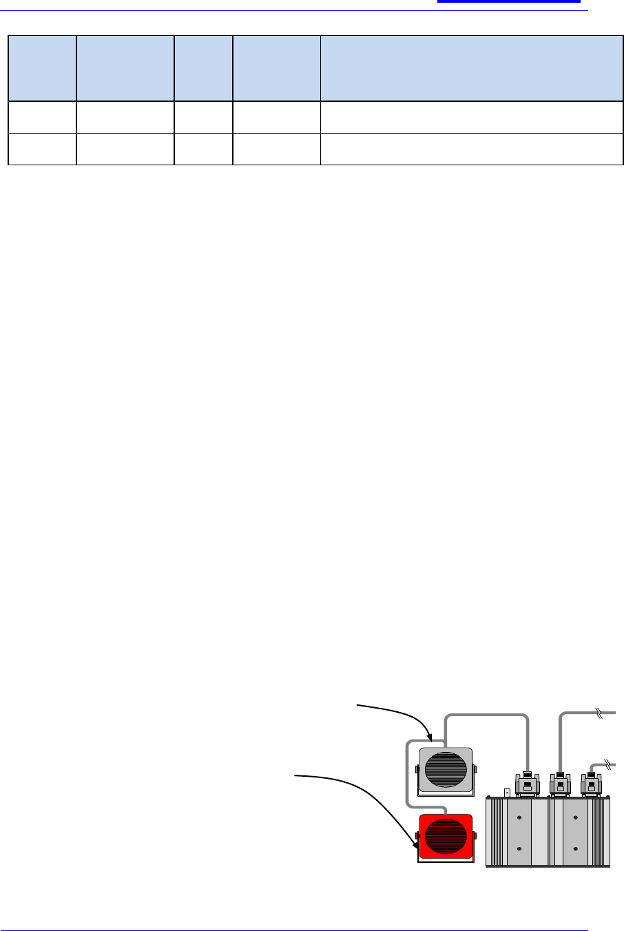
SPEAKER CONFIGURATIONS
Typically only one 4ohm 8w speaker is connected to the
transceiver
However the speaker driver is rated to support two parallel
4ohm speakers in a balanced 2 ohm configuration as shown
below.
No dual speaker adapter cable is currently available from
Sepura, it is expected that the installer will manufacture an
appropriate splitter cable
5V supply
SB-P-06-4066
sepura
Mobile & Gateway Accessory i/f
specification
30th July 2012
Page 22 of 39
Issue 7c
© Sepura plc 2011
AUDIO ACCESSORY INTERFACE (AAI)
There are two AAI ports designated AAI1 and AAI2 located on the Console and AIU. A subset
of AAI2 connections are duplicated on two jack sockets on AIU Mk1.
AIU Mk2 supports the AAI2 interface via jack connectors only.
NOTE:- Audio side-tone is permanently present for all accessories!
CONNECTOR DETAILS
Header: Sepura 3513 999 99316
Mating plug: Hirose number DF11-10DS-2C
SIGNAL DETAILS
Pin
Number
Signal
Name
Input/
Output
Description
Comment
1
ACC_ID
I
Accessory
Identity
5V ADC input with internal 47k pull-up. See
section 6.3
2
GND
-
Main Ground
return
-
3
SCN
-
Screen
Connection
-
4
ACC_KE
YS
I
Accessory Keys
5V ADC input with internal 330R pull-up. See
section 6.4
5
nON_HO
OK
I
Hook Signal
5V CMOS input, active low.
Internal 47k pull up to 5V
6
nPTT
I
PTT input
5V CMOS input, active low.
1 3 5 7 9
2 4 6 8 10
Connector viewed from the rear of the Console or AIU.
SB-P-06-4066
sepura
Mobile & Gateway Accessory i/f
specification
30th July 2012
Page 23 of 39
Issue 7c
© Sepura plc 2011
Pin
Number
Signal
Name
Input/
Output
Description
Comment
Internal 47k pull up to 5V
7
MIC_SIG
I
Microphone
input
Console & AIU mk. 1, 2, 3
Sensitivity at ―normal‖ setting = 100 mVpp for
max. modulation.
Sensitivity at default ―high‖ setting = 10 mVpp for
max. modulation.
DC bias via internal 2.2 kΩ pull-up to 3 V when
microphone enabled; floating when microphone
muted. Zin = 2.2 kΩ.
AIU mk. 2 1, 3
Sensitivity at default ―normal‖ setting =
150 mVpp for max. modulation.
Sensitivity at default ―high‖ setting = 15 mVpp for
max. modulation.
DC bias via internal 4.4 kΩ pull-up to 3 V.
Zin = 1 kΩ.
If microphone resistance < 100 Ω, “high” sensitivity
is selected. Sensitivity = 15 mVpp for max.
modulation.
8
MIC_GND
-
Microphone
return
-
9
EAR_SIG
O
Earpiece output
32 ohms, power capability = approx 100 mW max.
(See note 7 below)
10
EAR_GN
D
-
Earpiece return
-
Notes:
1. Transceiver gain set to reference level, see section 6.5
2. The AIU Mk1 has been superseded by the AIU Mk2.
3. There are two audio gain settings: ―normal‖ intended for handheld microphones and
―high‖ intended for remote microphones. If the audio accessory identification resistor
(see section 6.3) is 10 kΩ, or greater, the ―normal‖ gain setting is selected. ―High‖
gain (20 dB higher than ―normal‖ gain) is always selected when the audio accessory
identification resistor is 0 Ω, i.e., ACC_ID is connected to ground.
4. AIU Mk2 only If the microphone resistance is < 100 Ω, the gain will be ―high‖. This
functionality is intended to allow dynamic microphones to operate with this interface
— as used in certain motorcycle helmet installations.
SB-P-06-4066
sepura
Mobile & Gateway Accessory i/f
specification
30th July 2012
Page 24 of 39
Issue 7c
© Sepura plc 2011
Accessory ID resistor
Microphone resistance
Gain setting
≥ 10 kΩ
> 1 kΩ, e.g., electret
―Normal‖
≥ 10 kΩ
< 100 Ω, e.g., moving
coil (AIU Mk2)
―High‖
0 Ω
any value
―High‖
5. The earpiece amplifier does not have any output current limiting resistors fitted and is
designed to drive loads with a minimum impedance of 8 Ω loads from a 5 V supply
6. The transceiver mutes the microphone by turning off the electret microphone DC
supply on pin 7 of the AAI. If the audio source is not an electret microphone, then the
accessory must implement its own mute by detecting the loss of the DC voltage from
this pin.
7. When Normal gain is selected, the presence of a microphone load with a resistance
of less than 100 Ohms will automatically select a higher gain signal path. This
functionality is intended to allow dynamic microphones to operate with this interface -
as used in certain motorcycle helmet installations. The transceiver is unaware of any
gain change.
8. These signals and pin out are not compatible with SRM1000 accessories.
AUDIO ACCESSORY IDENTITY TABLE
The transceiver identifies audio accessories attached to an AAI through the resistance
presented between pin 1 and pin 2 of each AAI.
Audio Accessory Type
Associated identifying
resistor value, ohms
(2%)
Nominal
voltage on
ACC_ID pin, V
Nominal
ADC value
no device attached
5
255
reserved
220k
4.1
210
local microphone, PTT & hook, (e.g. fist
microphone)
100k
3.4
173
local microphone, PTT, earpiece & hook
(e.g. handset);
47k
2.5
128
local microphone & PTT without hook
(e.g. desk microphone)
22k
1.6
82
local microphone, PTT & earpiece without
hook (e.g. headset)
10k
0.88
45
remote microphone & switches without
hook;
0
0
0
ACCESSORY KEYS TABLE
The transceiver identifies which accessory key is pressed through the resistance presented
between pin 4 and pin 2 of each AAI.
SB-P-06-4066
sepura
Mobile & Gateway Accessory i/f
specification
30th July 2012
Page 25 of 39
Issue 7c
© Sepura plc 2011
Device state
Key press
Nominal voltage on ACC_KEYS
pin, V
Nominal ADC value
not attached
N/A
5.00
255
attached
None
4.51
230
attached
0
3.94
201
attached
1
3.35
171
attached
2
2.70
139
attached
3
2.00
102
attached
4
1.46
74
attached
5
0.85
44
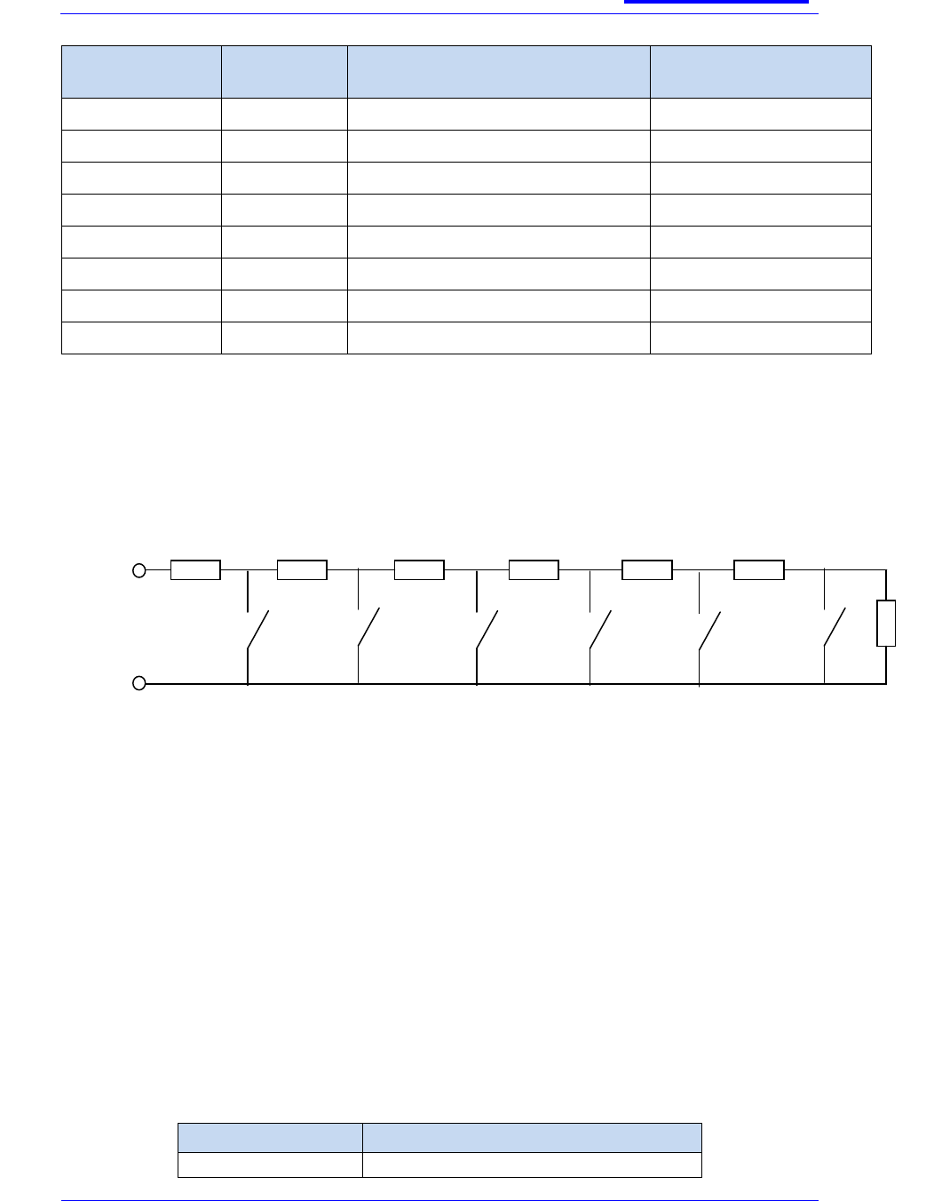
The accessory keys use a circuit structure like that given below. Resistor values and
associated logical key numbers (which map to functions specified by the Radio Manager) are
as follows:
AUDIO GAIN
Different microphones require different gains settings, e.g., a fist microphone will usually
require a lower gain setting than a remote microphone.
The audio gains of different microphone categories, e.g., fist microphone and headset, can be
adjusted over a 45 dB range via Radio Manager. This gain variation takes place in the
transceiver and is in addition to the console and AIU sensitivity settings, ―normal‖ and ―high‖,
described in section 6.2. The sensitivities for the console and AIU stated in section 6.2 are
achieved when the transceiver audio gain - programmable via Radio Manager - is set to
24 dB.
Accessory
Radio Manager default setting
Covert microphone
30 dB
68R
68
RR
R
82
R
180
R
270
R
560R
5
3
4
2
1
0
ACC_KEYS
GND
Key number =
1800R
SB-P-06-4066
sepura
Mobile & Gateway Accessory i/f
specification
30th July 2012
Page 26 of 39
Issue 7c
© Sepura plc 2011
Radio manager
includes default
transceiver gain
settings for various
accessories, but if these are incorrect for a particular customer‘s needs, the gain can be
programmed to any setting within the 45 dB range.
AIU MK 1 JACK CONNECTORS
Jack sockets provide an alternative method for connecting audio accessories to the AIU Mk1.
The jack sockets are an alternative format for the AAI2 connector.
One Jack socket designated ‗MIC‘ supports:
Microphone audio.
Accessory ID.
The other Jack socket designated ‗PTT‘ supports:
PTT.
Accessory key 5 only.
It should be noted that in the AIU Mk1 the Jack sockets share the AAI2 audio
connections; hence accessories must not be plugged in to the Jack sockets and the
AAI2 connector at the same time.
CONNECTOR DETAILS
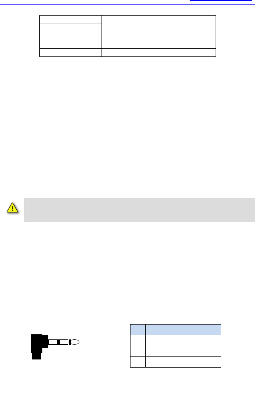
Stereo 3.5mm Jack socket. Mechanical latching is provided by securing the jack plug body to
features in the AIU mounting plate
JACK SIGNALS
Jack Pin number Identification (for
reference):
MIC‘ Jack Socket:
Pin
Signal Name
1
GND
2
ACC_ID (AAI-2 Channel)
3
MIC_SIG (AAI-2 Channel)
Desk Microphone
Fist microphone
Handset
Headset
Remote microphone
27 dB
1
2
3
SB-P-06-4066
sepura
Mobile & Gateway Accessory i/f
specification
30th July 2012
Page 27 of 39
Issue 7c
© Sepura plc 2011
‗PTT Jack Socket:
Pin
Signal Name
1
GND
2
Jack key input
10 kΩ pull-up to 5 V in the AIU.
Connecting this pin to GND via a 22 kΩ (or less) resistance will
cause the console software to see ‗Accessory Key 5‘ pressed on
AAI2.
3
nPTT (AAI-2 Channel)
Note if an SRH side jack microphone is connected in the via the microphone jack socket, the
ACC_ID signal will be shorted to GND (pins 1 and 2 shorted) by the mono jack plug, so the
remote microphone accessory will be detected correctly
AIU MK 2 JACK CONNECTORS
On the Mk 2 version of the Accessory Interface Unit (AIU) some of the pin functionality is re-
allocated on the AAI2 connector and the connector is renamed ―Remote Control Interface‖
(RCI) (see section 7).
The AIU Mk 2 has a VOGAD circuit in line with both of the microphone paths. The gain on the
AAI1 and AAI2 mic paths can be locally varied according to the type of microphone connected
and a microphone detect function is provided on AAI1.
AAI2 – VIA JACK CONNECTOR
For AIU Mk 2 the AAI2 audio input functionality is only available via the jack connector. The
performance and expected signal properties are slightly different from those of AIU Mk 1.
Jack Pin
Number
Signal
Name
Input/
Output
Description
Performance
3
MIC_SIG
I
Microphone input
Normal gain: 150mVrms nominal
High gain: 15mVrms nominal
Low gain: 1.2 Vrms nominal.
2.2 kΩ internal pull up to 8V.
The higher bias voltage and the addition of microphone load detection, allow this interface to
operate with active remote microphones e.g.

SB-P-06-4066
sepura
Mobile & Gateway Accessory i/f
specification
30th July 2012
Page 28 of 39
Issue 7c
© Sepura plc 2011
Accessory ID resistor,
ACC_ID2
Microphone resistance or current
Gain setting
≥ 10 kΩ
> 20 kΩ (< 0.4 mA), e.g., passive
electret
―Normal‖
≥ 10 kΩ
< 100 Ω, e.g., moving coil
―Low‖
≥ 10 kΩ
≥ 1.5 mA, e.g., active electret
―Low‖
0 Ω
> 20 kΩ (< 0.4 mA), e.g., passive
electret
―High‖
SB-P-06-4066
sepura
Mobile & Gateway Accessory i/f
specification
30th July 2012
Page 29 of 39
Issue 7c
© Sepura plc 2011
RCI CONNECTIONS
The RCI is present on the AIU Mk2 only. It allows an RCU to control the features of the
transceiver without using the radio console
CONNECTOR DETAILS
Header: Sepura 3513 999 99316
Mating plug: Hirose number DF11-10DS-2C
SIGNAL DETAILS
Pin
Number
Signal Name
Input/
Output
Description
Performance
1
8V5
O
Supply output
Supply output to power remote
control devices.
8.5v Current limited to ~500mA
2
GND
-
Main Ground return
-
3
DATA
I/O
1-wire data
3v Logic Levels, Sepura proprietary
protocol (see note 1 below)
4
ACC_KEYS
I
Accessory Keys
5V ADC input with internal 330R
pull-up. See section 6.4
5
nON_HOOK
I
Hook Signal
5V CMOS input, active low.
Internal 47k pull up to 5V
6
nPTT
I
PTT input
5V CMOS input, active low.
Internal 47k pull up to 5V
1 3 5 7 9
2 4 6 8 10
View looking at connector mounted on the AIU Mk 2 PCB.

SB-P-06-4066
sepura
Mobile & Gateway Accessory i/f
specification
30th July 2012
Page 30 of 39
Issue 7c
© Sepura plc 2011
7
MIC_OUT_SIG
O
Microphone output
Buffered version (0dB gain) of the
Jack Microphone input signal. AC
coupled with internal 6k8 load
resistor to MIC_OUT_GND (see note
3)
8
MIC_OUT_GND
-
Microphone output
return
9
EAR_SIG
O
Earpiece output
32 ohms, power capability = 100 mW
max (see note 2 and 3 below).
10
EAR_GND
-
Earpiece return
-
Notes:
One wire data for support of an RCU such as the Sepura 300-00164
The earpiece amplifier does not have any output current limiting resistors fitted and is
designed to drive a minimum of 8ohm loads from a 5V supply.
The MIC_OUT and EAR signals are no longer supported within the software for this interface.
SB-P-06-4066
sepura
Mobile & Gateway Accessory i/f
specification
30th July 2012
Page 31 of 39
Issue 7c
© Sepura plc 2011
DESK MOUNT UNIT CONNECTORS
The transceiver may be mounted within the case and the console mounted on top of a Desk
Mount Unit to facilitate operation outside of a vehicle.
The Audio Accessory Interface signals from the AAI1 connector on the back of the Console
are cabled to a 9-way ‗D‘ socket and a ¼‖ jack socket to allow for connection of a range of
desk accessories.
DESK MICROPHONE/HEADSET CONNECTOR
CONNECTOR DETAILS
9-way, standard density D-socket, with 2 off 4-40UNC hex pillars.
SIGNALS
The following signals connect back to the AAI1 connector in the back of the Desk Mount Unit
console. See section 0 for Signal details.
Pin
Signal
Name
Comments
1
ACC_ID
See section 6.3
2
GND
See section 6.2
3
ACC_KEYS
See section 6.4
4
EAR_SIG
See section 6.2
5
EAR_GND
See section 6.2
6
nON_HOOK
See section 6.2
7
MIC_SIG
See section 6.2
8
MIC_GND
See section 6.2
9
nPTT
See section 6.2
Shell
GND
FOOT SWITCH CONNECTOR
CONNECTOR DETAILS
Panel mounted, ¼‖ 3-pole jack socket with a mechanical latching mechanism. (e.g. Neutrik
NJ3FP6C).

SB-P-06-4066
sepura
Mobile & Gateway Accessory i/f
specification
30th July 2012
Page 32 of 39
Issue 7c
© Sepura plc 2011
SIGNALS
Pin
Signal
Name
Comment
Sleeve
GND
GND
Ring
GND
GND
Tip
nPTT
See section 6.2
LOUDSPEAKER CONNECTOR
The Desk Mount Unit has an internal speaker. Connection to the speaker is made on the rear
of the unit where there is a 2-pin plug which will accept the speaker connector form the Desk
Mount Unit power supply lead.
SB-P-06-4066
sepura
Mobile & Gateway Accessory i/f
specification
30th July 2012
Page 33 of 39
Issue 7c
© Sepura plc 2011
DATA CONNECTOR INTERFACE
A single Data Interface Connector is located on:
The lower surface of the Console.
On the outside of the AIU.
CONNECTOR DETAILS
Connector Type: 15 way high density female D type. Type JST KSEY-15S-1A3F19-13
SIGNAL DETAILS
Pin
Signal Name
Signal Function
Signal Function &
Signal Characteristics
1
AODO1/MIS
O
Console Programming &
Programmable I/O -Output
Open drain, active low.
500mA max sink current
15.8V max external voltage
Protected against inductive loads.
An external 10 kΩ pull-up resistor to 5V is
required for console programming. See {1} for
details
VOLmax = 300mV
2
MOSI
Console Programming -
Input
5V logic. See {1} for details.
3
nReset
Console Programming - Input
5V logic. See {1} for details.
4
SCK
Console Programming - Input
5V logic. See {1} for details.
5
5V
Console Programming -
Output
5V nominal, 10mA max.
Not protected against misuse.
6
AGPI_11
Programmable I/O - Input
VIH min = 2.0V
11 12 13 14 15
1 2 3 4 5
6 7 8 9 10

SB-P-06-4066
sepura
Mobile & Gateway Accessory i/f
specification
30th July 2012
Page 34 of 39
Issue 7c
© Sepura plc 2011
Pin
Signal Name
Signal Function
Signal Function &
Signal Characteristics
VIL max = 0.8V
Protected against accidental application
of vehicle supply voltage
Assertion time: >100ms
7
AGPI_21
Programmable I/O - Input
VIH min = 2.0V
VIL max = 0.8V
Protected against accidental application
of vehicle supply voltage
Assertion time: >100ms
8
AGPI_31
Programmable I/O - Input
VIH min = 2.0V
VIL max = 0.8V
Protected against accidental application
of vehicle supply voltage
Assertion time: >100ms
9
RS232_DCD
RS232 Data
See section 4.4
10
RS232_RXD
RS232 Data
See section 4.4
11
RS232_TXD
RS232 Data
See section 4.4
12
RS232_RTS
RS232 Data
See section 4.4
13
RS232_CTS
RS232 Data
See section 4.4
14
RS232_DTR
RS232 Data
See section 4.4
15
GND
-
See section 4.4
Metal
shell
Screen
-
See section 4.4
Notes
There is a pull-down resistance on each digital input. The resistance to ground, will vary in the
range 10k to 27k ohms depending on the applied input voltage, this because there is a
resistor divider network feeding a resistor junction
Only the AIU supports digital inputs or outputs, the console does not.

SB-P-06-4066
sepura
Mobile & Gateway Accessory i/f
specification
30th July 2012
Page 35 of 39
Issue 7c
© Sepura plc 2011
ANTENNA’S
CONNECTOR DETAILS
Type: BNC socket.
SIGNAL DETAILS
Pin
Signal Name
Signal Function
Signal Function &
Signal Characteristics
Centre
ANTENNA
Main TETRA RF input/output
10W max average power (20W max.
peak) during transmission
DC grounded internally using 100K
resistor
Outer
GND
Ground return
Ground

SB-P-06-4066
sepura
Mobile & Gateway Accessory i/f
specification
30th July 2012
Page 36 of 39
Issue 7c
© Sepura plc 2011
GPS ANTENNA
CONNECTOR DETAILS
Type: SMC female (on the radio).
SIGNAL DETAILS
Notes:
The GPS circuitry within the SRM/G will operate with a passive antenna. However due to
cable loss an active antenna with LNA gain between 20dB and 30dB is advised to counter the
cable loss. Sepura supplied GPS antennas have an LNA gain of 26dB to counter a 5dB loss
in 5m coax cable.
Active antenna‘s draw 5V dc at up to 40mA.
Pin
Signal
Name
Signal Function
Signal Function &
Signal Characteristics
Centre
GPS_ANT
GPS RF input and
active antenna DC
feed
Vnom.5V
I max.40mA
Internally protected against external short
circuits to ground.
RF input from GPS antenna = 1575.42 MHz
(L1 Band) at a level between –135 dBm and –
152 dBm into a 50 Ω impedance.
LNA gain see note 1 below
Outer
GND
Ground return
Ground
SB-P-06-4066
sepura
Mobile & Gateway Accessory i/f
specification
30th July 2012
Page 37 of 39
Issue 7c
© Sepura plc 2011
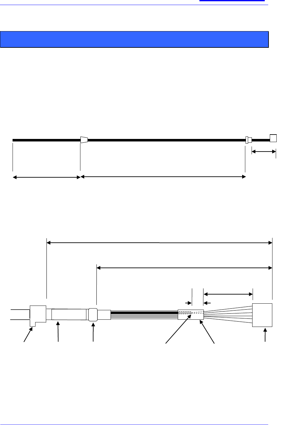
CONSOLE AND AIU CABLE SPECIFCATION
In order to connect audio accessories to the Console or AIU, the cable form and its retaining
grommet should adhere to the following specification:
CABLEFORM MECHANICAL DETAILS
Overall dimensions
Plug Termination
Stripped section: 76 +/- 2 mm
116+/-2mm
Plug
grommet:
see section
12.2
Identifier:
Ø = 5.5mm max
x 25mm typ
Sleeve over jacket
breakout:
Ø = 6mm max
x 10mm typ
See note 3
Hirose
Plug
20 mm min
Sleeve over any mic
coax break-out and
other wires: 10mm
typ.
Mic coax
break-out
See note 2
5 mm
typ
Less than 3000mm (see note 1)
ØOD = 5.2 +/- 1mm
116 ± 2mm
Accessory termination
Plug termination
As required for
accessory termination
SB-P-06-4066
sepura
Mobile & Gateway Accessory i/f
specification
30th July 2012
Page 38 of 39
Issue 7c
© Sepura plc 2011
Notes:
The complete overall length of cable for any accessory including any extension leads must
not exceed 3000mm.
Longer cable lengths will require Sepura to obtain further approvals before the
accessory may be used, the costs re-approval will be borne by the accessory
designer/manufacturer.
In order for the accessory to achieve the required conformity, it is recommended that the
cable be overall screened and Mic signals to be additionally screened.
To avoid shorting any exposed length of overall drain and microphone screen must be
sleeved with a tight fitting heat shrink to achieve a shrunk-down diameter of approximately
1mm to fit into the insulation crimp of the Hirose pins.
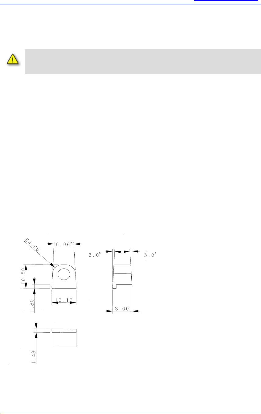
CABLE FORM GROMMET
Tolerance: linear dimensions ± 0.1mm, angles ± 1º
Projection: 3rd angle
Fixing method: moulded onto cable.
Material: polyurethane type 58300, shore hardness 80A, colour black.
Pull force: Grommets to withstand a minimum pull force of 100N.
Tooling: Sepura Development to approve gate position prior to tool manufacture.
Surface finish: polished

SB-P-06-4066
sepura
Mobile & Gateway Accessory i/f
specification
30th July 2012
Page 39 of 39
Issue 7c
© Sepura plc 2011
NOTICE
All rights reserved. This document may not be reproduced in any form either in part or in
whole without the prior written consent of Sepura plc, nor may it be edited, duplicated or
distributed using electronic systems.
Company and product names mentioned in this document may be protected under copyright
or patent laws.
The information in this document is subject to change without notice and describes only the
product defined in this document. This document is intended for the use of Sepura customers
and/or other parties only for the purposes of the agreement or arrangement under which this
document is submitted, and no part of it may be reproduced or transmitted in any form or
means without the prior written permission of Sepura plc.
CONTACT DETAILS
Sepura plc
Radio House
St Andrew‘s Road
Cambridge CB4 1GR
United Kingdom
Web :
www.sepura.com
Tel:
+44 (0)1223 876000
Fax:
+44 (0)1223 879000