Sepura SRG3500XB TETRA Mobile/Gateway Terminal User Manual SPR DOC 00117 8
Sepura plc TETRA Mobile/Gateway Terminal SPR DOC 00117 8
Sepura >
Contents
Installation guide
4
Sepura plc., Radio House,
St. Andrew’s Road, Cambridge,
CB4 1GR, England.
www.sepura.com
© SPR-DOC-00117
Issue 8
Remote Microphone and Switches Installation (optional)
It is recommended that the microphone is located away from any wind noise in a position
suitable for the operator(s), e.g., near internal rear view mirror.
The switch unit should also be located centrally for the operator(s) to access. A self
adhesive hook and loop pad is provided for mounting the remote PTT on a flat surface,
e.g., dashboard.
Only one hands free microphone can be used in an installation, which can be connected
to either audio accessory interface.
Termination to console connector
The remote microphone is supplied un-terminated for ease of installation. Terminate to
the console as shown below after the switch unit and microphone are positioned.
Cable entry - Standard Console
Dress the cables via the small guide channel at the bottom of the console. Fit the split
bung and the cable tie (supplied) around the cables. Press the bung into the recess in
the channel. Tighten the cable tie behind the bung to secure the cables and allow slack
at the 10-way plug termination.
Note: when used in conjunction with a handset or fist-microphone accessory the hands
free kit must be plugged into the Audio Accessory Interface 1 connector (back left) to
allow all cables to be routed correctly (see front page illustration).
Cable entry - Handset Based Console
Dress the cables via the small guide channels at the bottom end of the cradle box (the
microphone channel is slightly smaller). The cables are gripped when the lid is secured.
Fist Microphone/Handset (optional)
The Fist microphone and/or Handset should be located centrally for the operator(s) to
access, using the screws provided. Ensure that the cables are placed in the rear of the
console so that the grommets seal correctly.
Multiple Fist Microphones and/or Handsets may be connected in an installation, which
may be connected to either audio accessory interface.
Loudspeaker
The loudspeaker should be positioned so that it faces the operator, but is out of the line
of sight of the Remote Microphone.
Programmable I/O
The transceiver supports 4 programmable digital I/O lines: 3 inputs and 1 output.
The following functions may be allocated on the input lines:
• External Alarm Input
• External Input Triggered Status Messages
The following functions may be allocated on the output line:
• External Alert Output
• Status Message Triggered External Outputs
For details of how to programme the functions refer to the Sepura Programmer.
For details of the signals and their characteristics, see table below.
Wire
Colour Description Performance
Orange Programmable
input 1
VIH min = 2.0 V
VIL max = 0.8 V
Protected against accidental application of
vehicle supply voltage
Assertion time: >100 ms
Yellow Programmable
input 2
VIH min = 2.0 V
VIL max = 0.8 V
Protected against accidental application of
vehicle supply voltage
Assertion time: >100 ms
Green Programmable
input 3
VIH min = 2.0 V
VIL max = 0.8 V
Protected against accidental application of
vehicle supply voltage
Assertion time: >100 ms
Pink Programmable
output
Open drain, active low.
500 mA max sink current
15.8 V max external voltage Internally
protected against inductive loads, and with
a re-settable fuse.
VOL max = 200 mV @ 0.5 A
WARNING
To control devices from the programmable output which require more than
0.5 A, use a suitable automotive relay to ensure correct operation. Connect
the relay coil between the output wire and the vehicle positive supply. The
device must be protected by an appropriate fuse in its positive supply.
Check with the local regulatory authority where the output is used to drive
external alert devices such as horns or sirens.
Installation with a Mobile Data Terminal (MDT)
This guide does not include specific details about installing with a MDT. However, it is
recommended that the 15-way D-type connector on either the console or an unused
console interface on the transceiver, is used to connect an MDT with a Sepura data lead
(300-00065).
If a spare 15-way interface is not available, connect a Console Interface Box (300-00221)
between the transceiver and console using remote console cables not exceeding 10 m in
total length. Connect the MDT to the spare 15-way connector on the interface box.
Customising/Programming the Mobile Radio
To customise or re-program the internal software in the mobile radio you will need the
following items:
Sepura Programmer Kit
Mobile Radio Power/Audio lead
Mobile Radio Data lead
Connect the power lead to the power connector on the rear of the transceiver. The red
and black wires in the power lead should be connected to a suitable power supply set to
12 V nominal with a rating of 5 A. The blue ignition wire in the power lead should be
connected to the positive terminal on the power supply. All other wires may be left
unconnected.
Connect the Data Lead to either of the 15-way D-type Interfaces on the transceiver or to
the Data Connector on a console, if connected. Connect the other end of the data lead
to a COM port on a PC loaded with the Programmer.
RF Compatibility Checks
The following checks must always be carried out if the vehicle is equipped with electronic
anti-skid, electronic ignition or engine management systems.
The transmitter should be operated only for the time required to make an observation.
The transmitter should be operated on a TETRA System, or these checks will have to be
carried out in DMO.
An assistant will be required for the following checks.
1 With the vehicle stationary and the engine running at fast idle, operate the
transmitter. Check that the brake lights do not illuminate and that the engine
continues to run normally, i.e., with no surging or cutting out.
2 Operate the brake pedal, key the transmitter and check that the brake lights do not
extinguish.
3 Put the vehicle into motion at a speed of 15 - 25 km/h (10 – 15 mph), key the
transmitter and operate the brake pedal simultaneously. Check that the braking
action is normal and that the engine does not surge or cut out.
WARNING
In the event of an apparent malfunction in the braking or any other systems
during RF compatibility checks, the transceiver installation should be
rendered inoperative and the vehicle manufacturer should be contacted
before any further use is made of the transceiver installation.
Unqualified persons should not attempt to modify these units in any way.
NOTICE
Sepura Mobile Transceivers have a small rechargeable internal back-up
battery. This battery powers the internal Real Time Clock in the event that
the main power to the product is removed. The battery may have discharged
during the manufacturing process or if the product has been in storage for
some time. Once the product is connected to its main supply, the back-up
battery will charge regardless of whether the product is turned on or not. The
charge period for a full charge may be up to 48 hours.
Mobile Radio Series Vehicle Accessories
Part Number
Description
300-00061 Handset (for use with standard console only)
300-00062 Fist Microphone (for use with standard console only)
300-00064 Small Loudspeaker
300-00088 Large Loudspeaker
300-00082 Loudspeaker Extension Cable
300-00065 Data Lead
300-00066 Power Cable (supplied with transceiver)
300-00067 Console Cable 0.5m
300-00068 Console Cable 2m
300-00664 Console Cable 3m
300-00069 Console Cable 5m
300-00665 Console Cable 7m
300-00079 Remote Microphone and 2 Switches
300-00080 Standard Console Rear Panel Kit
300-00081 DIN Fascia Kit
300-00083 Standard Console
300-00084 Standard Console Pivot Mount Kit
300-00086 Transceiver Mounting Kit (supplied with transceiver)
300-00087 Applications Interface Unit (see supplementary install guide)
300-00629 Car Cradle Fixing Kit
300-00721 4-Hole AMPS Mounting Kit 1
300-00668 Handset Based Console (HBC) Kit
300-00669 Handset Based Console (HBC)
300-00670 Handset Based Console (HBC) Interface and Handsfree Box
300-00671 Handset Based Console (HBC) Mounting Bracket Kit
- Antenna (band dependent, contact sales)
Soft Key 5*
Switch Unit
Remote
Microphone
Cable
Tie
Split
Bung
Standard Console only:
Crimp-entry
View of
10-way plug
PTT
1
3
2
6
4
5
8
7
Identification
link
Microphone
termination
10
9
*Standard Console only
Installation Guide Sepura Mobile
Transceivers sepura
WARNING
Do NOT operate your Sepura mobile radio in an explosive atmosphere.
Obey “Turn OFF Two-Way Radios” signs where posted.
Do NOT touch the antenna when the radio is turned on.
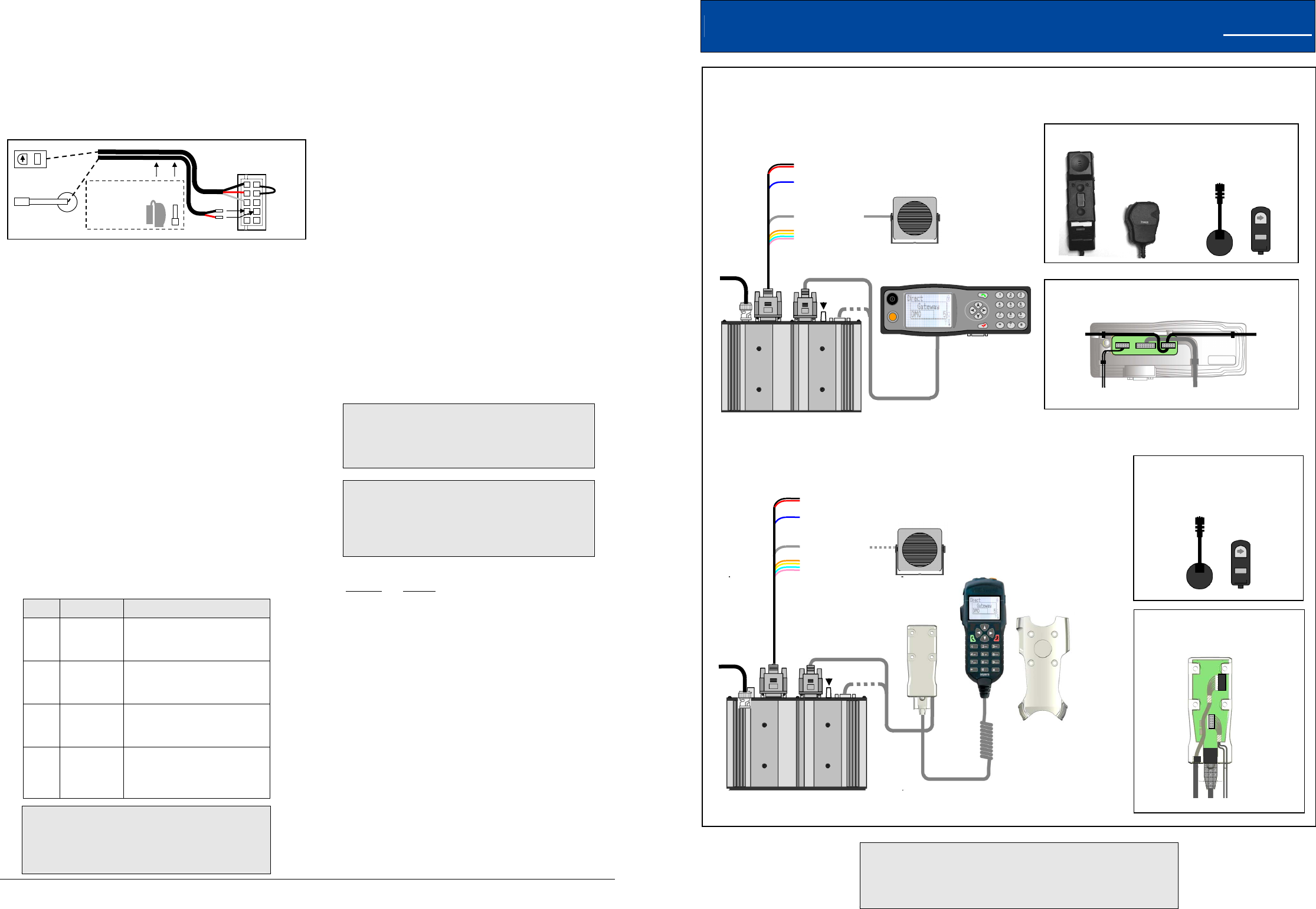
Standard Console option + Accessories
+ Accessories
Console options and accessories
Any combination of two consoles may be connected.
Handset
Fist
microphone
Remote Microphone
& Switches
Remote Microphone
& Switches
Handset
Connector view
inside Interface &
Handsfree B
ox
Standard Console
Vehicle battery (via fuse provided)
Ignition switch (via fuse provided)
Loudspeaker
Programmable I/O
Vehicle harness:
Remote Console
Cable
Tetra
Antenna
GPS Ant.
Transceiver
Connector view
at rear of Standard Console
Handset Based Console option
Vehicle harness:
Remote Console
Cable
Handset
Based
Console
Vehicle battery (via fuse provided)
Ignition switch (via fuse provided)
Loudspeaker
Programmable I/O
Tetra
Antenna
GPS Ant.
Transceiver
Bracket
Interface
& Handsfree
Box
PTT
Soft
Key 5
PTT
No function
Transceiver
Handset
or Fist mic.
Remote Microphone
& switches (see P4 for details)
Handset
or Fist mic.
(alternative entry)
Transceiver
Remote mic.
& switches
(see P4 for details)
2
Important Information
The transceiver is designed for nominal 12 V negative earth systems.
The equipment is to be installed in accordance with the requirements of local
radio communications authorities and/or Health and Safety regulations.
12 V supply leads, antenna cables and speaker wiring is to be routed as far away as
possible from gas or fuel lines, and any in-vehicle electrical wiring. This reduces the risk
to safety in the event of a leak.
The transceiver should be positioned so that it does not obstruct, or become at risk of
damage from, any occupant or carried items. All cabling should be hidden and not left
loose.
Unpacking
Unpack the container(s) and ensure all items specified on any delivery note are present.
The manufacturer, or their authorised agents, must be notified within ten days of
receipt of equipment if any damage or shortages are found
(customer.support@sepura.com).
No accessories are shipped in the box with the transceiver, except the Power
Cable Assembly and the Transceiver Mounting Kit. Due to the many combinations
available the accessory pack must be specified at time of ordering.
Note: the Handset Based Console option is packed separately.
Operator Access and Safety
The console must be fitted in such a position that the operators have easy access to the
controls and the microphones when wearing a seat belt. The controls must also be
within the driver's normal field of vision.
Fitting positions above the driver's or passenger's head, or in other positions where the
unit would present a hazard in an accident, must be avoided.
The microphone/handset hook mount must be fitted such that the microphone/handset is
easily accessible and the cable cannot interfere with the vehicle control, or with the
driver's feet.
Preferably, the loudspeaker should be installed such that the grille is facing the operator,
but out of sight of the remote hands-free microphone (if fitted).
Installation
This installation guide provides basic installation information and is not intended to be
definitive, as different types of vehicles will require different installation configurations.
The installer must ensure that fixing screws of an appropriate length are used (some
installations may require different screws). The information given here is general and for
guidance only.
The installation should comply with FCS 1362 CODE OF PRACTICE for the installation
of mobile radio and related ancillary equipment in land based vehicles - see
http://www.fcs.org.uk.
Installation Precautions
Motor vehicle manufacturers make use of electronic vehicle control systems, e.g.,
ignition, anti-skid devices etc.
The following information is supplied to ensure that there is no radio frequency
interference effect upon the vehicle's electronic systems.
To prevent interference with any other electronic systems in the vehicle, the
antenna should be mounted as far away as possible from these units and their
associated cables. Refer to the vehicle manufacturer's handbook to locate these
items.
Consult the manufacturer's handbook to establish whether it is practical to
disconnect the vehicle battery without affecting devices, such as central locking
mechanisms, engine management computers, security-coded in-car entertainment
units etc.
WARNING
1. Disconnect the vehicle’s battery before commencing installation (be aware
of effect on public broadcast radio security code, alarm systems and some
engine management systems).
2. Do not smoke, or use naked flames, when working near the vehicle’s fuel
system.
3. Ensure that fuel lines, hydraulic lines and existing cables are not damaged
during installation.
4. Ensure that the installation does not impede the normal operation of the
vehicle, including the operation of any safety device, e.g., airbags and
seatbelt tensioners.
5. Speed control, fuel injection, anti-lock braking, navigation, air bag and other
electronic systems are relatively immune to RF interference. However, if
difficulty is experienced or faulty operation suspected, consult the vehicle’s
dealer.
6. This equipment is suitable for 12 V negative earth vehicles only. Use on
other supply systems will result in damage to the equipment.
7. No part of the equipment should be mounted such that injury to the
occupants is likely during an accident.
8. Prolonged operation of the transceiver with the vehicle engine switched off,
could drain the vehicle’s battery.
9. In order to reduce the risk of RF burns the antenna must always remain
connected whilst the equipment is switched on. Under no circumstances
should the antenna connection be connected or disconnected whilst the
equipment is switched on.
Specialised Vehicles
The installation on certain specialised vehicles, such as fuel tankers and fire-fighting
vehicles may be subject to additional safety regulations which must be closely observed.
Prior to commencing an installation on such a vehicle, make sure that any relevant safety
regulations are fully understood.
Petrol Powered Vehicles
Ensure that there are no petrol leaks before commencing an installation involving the use
of electric tools as these can produce sparks. Ensure that no damage to the petrol tank
or fuel lines occurs when drilling holes.
Gas Powered Vehicles
Before installation starts ensure that there are no gas leaks before commencing an
installation involving the use of electric tools as these can produce sparks. DO NOT
USE A NAKED FLAME. Butane and propane are heavier than air, so if there is a leak
the gas may lay on the floor of the boot. The gas is detectable by its characteristic smell.
The point of escaping gas may show signs of frosting. The vehicle owner should arrange
for the leak to be repaired before the installation is commenced.
Ensure that no damage to the gas tank or gas lines occurs when drilling holes. Supply
cables should be run, if possible, on the opposite side of the vehicle to the gas fuel pipe.
Vehicles Fitted with Electronic Devices
In theory, any vehicle electronic systems could be affected by the presence of an RF field
of sufficient intensity, which when detected may cause the device to malfunction. The
source of RF may be a mobile transceiver installed in the vehicle itself or one operating
in another vehicle in close proximity. If interaction did occur, loss of control could result
for the duration of the transmission.
In the interests of safety, the user must be asked to test the vehicle when the installation
is complete.
Installation Guidelines and Recommendations
Temperature Considerations
Reliable transmit operation will be achieved if the transceiver is mounted such that the
finned heatsink receives a free flow of air, i.e., if it is mounted in the normal vertical
orientation with no restriction to the flow of convected air. For any other orientation,
varying degrees of degradation may result.
Fitting the transceiver or console on top of the dash is not recommended. Exposure to
direct sunlight may cause the temperature to rise to over 100 °C. Prolonged exposure to
these temperatures may damage the equipment and invalidate the warranty.
Do not mount the transceiver close to a heat source, e.g., in front of a heater vent.
Installing the Transceiver
Orientation Considerations
It is recommended that the transceiver is mounted within 15 ° of the vertical with the
connectors at the bottom; this reduces the effects of vibration and likelihood of
dust/moisture ingress. Ensure the heatsink fins are in free air as much as possible. The
heatsink may become hot after long periods of transmission; therefore, make sure that
accidental contact with the heatsink is not possible. Ensure sufficient space is provided
above the installation to allow fitment and removal of transceiver (see diagrams below).
Preferred Orientation Alternative Horizontal Orientation
Location Considerations
The transceiver must be fitted within the interior of the vehicle (excluding the engine
compartment) and protected from the external environment and vehicle cleaning
operations. When fitted, no part of the transceiver may be allowed to obstruct the
operation of the vehicle or impair the safety of any occupant.
Locate the transceiver away from cables carrying very high currents, e.g., the starter
motor cable or the electric traction motor, and its cables, of electric vehicles.
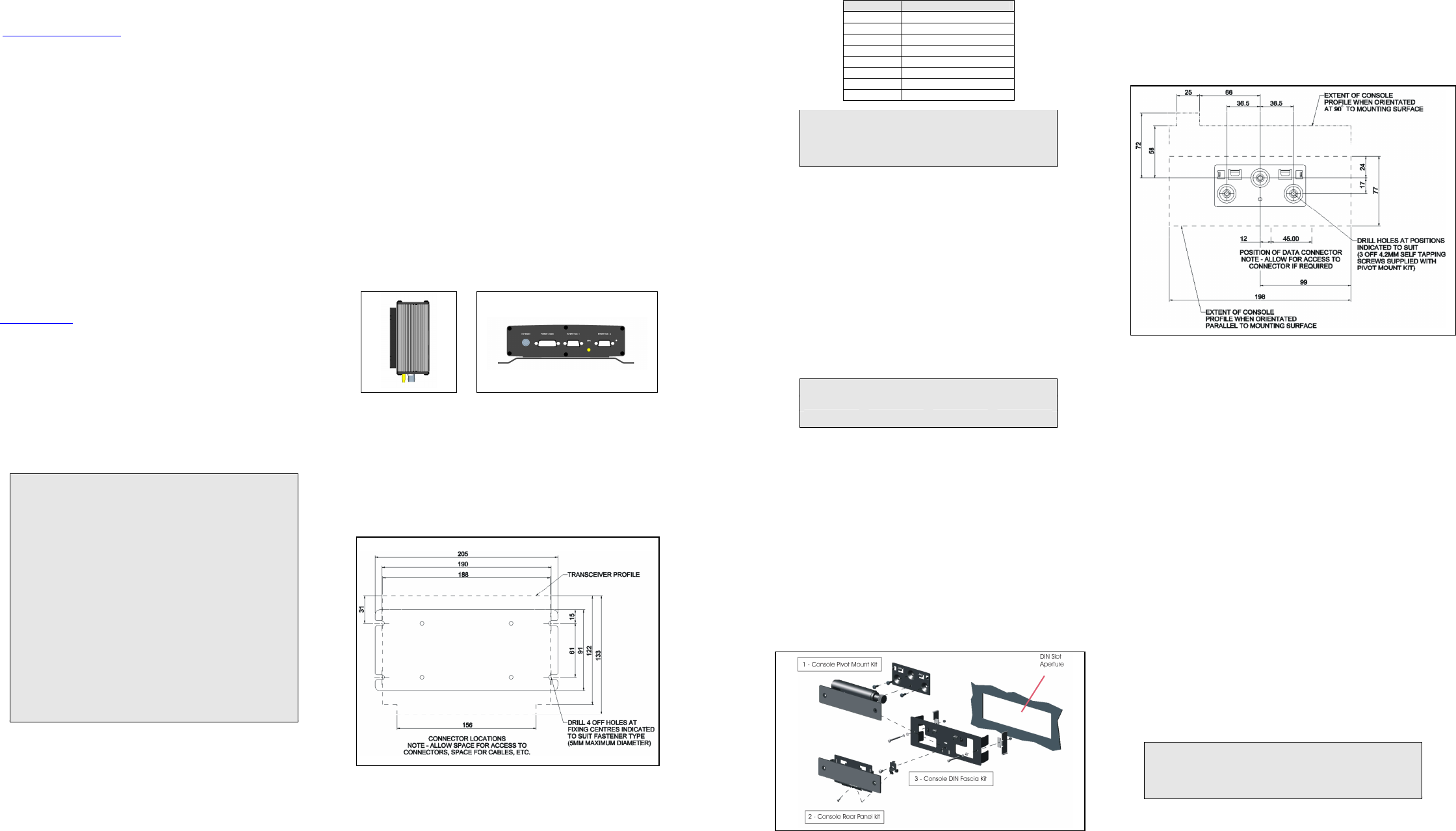
Transceiver Mounting Bracket Installation
The transceiver mounting bracket must be screwed to the desired surface using at least
four screws. The bracket may be used as a template.
Fixing Hole Positions for Transceiver Mounting Bracket (all dimensions in mm)
Transceiver profile includes small clearance allowance; additional allowances should be
made for cables depending on installation configuration.
3
Cables
Both the remote console and loudspeaker extension cables are colour coded blue at the
transceiver end to aid pre-installation before the transceiver is available.
Ensure that the remote console cable is routed so that it is kept well clear of the antenna
cable and of any other electronic devices such as electromagnetic systems or AM/FM
radios. One end of the remote console cable is plugged into the 16-way header on the
rear of the Standard Console (or Interface & Handsfree Box of Handset Based Console)
and the strain relief/environmental grommet located in place within the moulding. The
other end plugs into either of the “D-type” Interface sockets on the rear of the transceiver.
Do not connect or disconnect the console(s) while the transceiver is powered.
If a connector is unused, fit the dust cover provided.
Power/Audio Connector Wiring Colour Code
Wire Colour Description
Red Positive connection +12 V
Black Negative connection GND
Blue Ignition Sense
Grey Loudspeaker
Orange Programmable input 1
Yellow Programmable input 2
Light Green Programmable input 3
Pink Programmable output
WARNING
The transceiver will be damaged if either of the loudspeaker conductors
(grey twin conductor cable) is connected to ground. If the loudspeaker
output is to be connected to other audio systems, an audio isolation
transformer must be used.
DC Supply Connection
The power cable plugs into the rear of the transceiver utilising a 15 way D-type
connection. The cable also provides an ancillary connection point for function such as
loudspeaker and other special I/O functions.
1 With the transceiver end of the power connector resting in its intended final
position, route the wires to the vehicle battery; threading the cable through the
bulkheads if required (include the blue wire where ignition switching is not
required, see 4 below).
2 The positive power line must include a fuse as close as possible to the power
source. The negative power line must be connected close to the battery-to-
vehicle-body connexion (not directly to the battery) and must not include a fuse.
3 It is recommended that the power cable runs are kept as short as possible.
4 The blue wire provides an ignition sensing input. If ignition switching is required,
trim the wire to length so that it can be wired, via a fuse, to the ignition switch,
using the splicing connector provided. Otherwise this wire must be connected, via
a fuse, to the permanent positive supply. A fuse must always be fitted close to
where the wire is connected.
5 Check the installation and fit the blade fuses.
Fuse Ratings
Positive supply 10 A Ignition sense 1 A
Automotive 19 mm blade type (Littelfuse ATO®)
Antenna Installation
For best all round performance of the product, the antenna should be fitted on the centre
of the vehicle roof. Alternative positions, such as wing mounting, will give degraded
performance. The coaxial feeder should be secured along its length to eliminate the
possibility of damage by sharp edges or moving parts.
Antenna Installation - GPS (optional)
If a GPS receiver is fitted at time of manufacture, a GPS antenna socket will be fitted.
The antenna unit connects to a SMC connector on the rear of the transceiver and should,
ideally, be mounted on the highest point of the vehicle (i.e., roof) with an uninterrupted
view of the sky, and as far from the TETRA antenna as possible. For mounting, follow
manufacturer’s installation instructions. It is recommended to fit the GPS antenna
connector before connecting the Remote Control Cable.
An active antenna is recommended, the supply of which is on the centre pin, 5 V
nominal, 40 mA maximum. This supply feed is short circuit protected.
Standard Console Installation
Mounting Kits for Standard Console
Mounting the Standard Console on the Dash
The standard console is mounted into the desired position utilising the Console Pivot
Mount Kit.
This consists of two main parts:
The dash mount bracket onto which the support bracket is attached.
An adjustable support bracket onto which the console is fixed.
The dash mount bracket should be fixed to a suitable surface, using the three screws
provided. Ensure orientation is correct for the viewing situation (i.e., tilt up or tilt down)
and access is considered to the RS232 data connector, if required.
Ensure that the microphone(s) are connected and cables laid in the cable exits on the
rear of the standard console (see illustration on P4). Any unused cable exits should have
the provided bungs fitted. Fix the support bracket to the rear of console using screws
provided (tightening torque = 0.8 Nm). Avoid trapping the wire with the bracket during
assembly.
The support bracket then slots into the mounting bracket and is held by a single, fixed
sprung screw.
The viewing angle of the standard console can be adjusted by loosening the release
knob until the tilt mechanism is free enough to move, a ratchet action provides
incremental positioning. The knob should then be re-tightened fixing the console in
place.
Fixing Hole Positions for Standard Console Pivot Mounting Kit (all dimensions mm)
Console profile includes small clearance allowance; additional allowances should be
made for cables depending on installation configuration.
Mounting the Console in a DIN Slot
A DIN slot mounting bracket is also available for vehicles that have a spare DIN slot.
Following the diagram, above, fit the DIN fascia kit into the DIN slot using the screws
provided.
A self-locking nut should be fitted to the end of each of the two screws that secure the
DIN fascia, so that if the fascia is subsequently removed, the two grip plates are
prevented from fully detaching from the securing screws.
Either the rear panel kit or the pivot mount kit may be fitted with the DIN fascia. The
dash mount bracket supplied with the pivot mount kit is not required in this case.
Ensure that Microphone(s) are connected and cables laid in the cable exits on the rear of
the console (See illustration on P4). Any unused cable exits should have the bungs
provided fitted.
Fit either the Rear Panel Kit or the Pivot Mount Kit to the Console and then fit this
assembly to the DIN Fascia Kit. Fix either support bracket, or console rear panel, to rear
of console using screws provided. Avoid trapping wire with bracket during assembly.
Handset Based Console Installation
The handset based console is supplied with a magnetic mounting bracket and interface
box. The mounting bracket can be mounted separately or over the box using the screws
provided.
Note: the interface box is not sealed – avoid positions with risk of water or dust entry.
Connect the transceiver to the 16-way header in the interface box to the with the console
cable supplied. Ensure that the strain relief bung is seated at the cable entry in the box
front with flat face down. Refer also to “Cables” section at the top of this page.
(Refer to “Remote Microphone and Switches Installation” on P4 if this option is supplied.)
Press the inner wires of the Remote Console Cable into the clips on the PCB. Screw the
box halves together securely, taking care not to trap any wires.
Plug the handset based console into the interface box through the retaining clip and fold
the clip back over the plug body.
Place the handset in the mounting bracket with the display facing the user.
Additional mounting kits available separately:
300-00629 Car Cradle Fixing Kit: a knuckle joint which provides vertical tilt adjustment.
4-Hole AMPS Mounting Kit 1: additional brackets providing versatile mounting options.
IMPORTANT
The hole pattern of the mounting bracket for the handset based console is
compatible with AMPS standard mounting kits. If these are to be used, the
installer should check that the chosen kit is sufficiently rugged to suit the
user’s operating environment.