Sercomm WAP121 Wireless-N Access Point with Power over Ethernet User Manual
Sercomm Corporation Wireless-N Access Point with Power over Ethernet
Sercomm >
Contents
- 1. User manual 1 of 4
- 2. User manual 2 of 4
- 3. User manual 3 of 4
- 4. User manual 4 of 4
User manual 1 of 4
5(9,(:'5$)79HUVLRQ{&,6&2&21),'(17,$//
&LVFR6PDOO%XVLQHVV
:$3
:$3
$'0,1,675$7,21
*8,'(
Wireless-N Access Point with Power over Ethernet
Wireless-N Selectable -Band Access Point with
Power over Ethernet

Cisco Small Business WAP121 and WAP321 Wireless-N Access Point with PoE 2
REVIEW DRAFT Version 2—CISCO CONFIDENTIAL
&RQWHQWV
&KDSWHU*HWWLQJ6WDUWHG
Starting the Web-based AP Configuration Utility 7
Launching the Utility 8
Logging In 8
Logging Out 8
Using the Access Point Setup Wizard 9
Getting Started 10
Window Navigation 11
Application Header 11
Navigation Window 11
Management Buttons 12
&KDSWHU9LHZLQJ6WDWLVWLFV
System Summary 14
Network Interfaces 15
Traffic Statistics 16
WorkGroup Bridge Transmit/Receive 17
Associated Clients 18
TSPEC Client Associations 19
Rogue AP Detection 21
TSPEC Status and Statistics 25
TSPEC AP Statistics 26
RADIO Statistics 27
Email Alert Status 28
Log 29
&KDSWHU/$16HWWLQJV
Port Settings 30
LAN 31
Time Settings 33

Cisco Small Business WAP121 and WAP321 Wireless-N Access Point with PoE 3
REVIEW DRAFT Version 2—CISCO CONFIDENTIAL
&RQWHQWV
&KDSWHU:LUHOHVV6HWWLQJV
Radio 36
Networks 43
SSID Naming Conventions 43
VLAN IDs 44
Configuring VAPs 44
Configuring Security Settings 47
None (Plain-text) 47
Static WEP 47
Dynamic WEP 50
WPA Personal 51
WPA Enterprise 53
Scheduler 55
Adding Scheduler Profiles 56
Configuring Scheduler Rules 57
Scheduler Association 58
Bandwidth Utilization 58
MAC Filtering 59
Configuring a MAC Filter List Locally on the AP 59
Configuring MAC Authentication on the RADIUS Server 60
WDS Bridge 60
Work Group Bridge 62
QoS 65
WPS Setup 67
WPS Overview 68
Usage Scenarios 68
WPS Roles 69
Enabling and disabling WPS on a VAP 69
External and Internal Registration 70
Client Enrollment 70
Optional Use of Internal Registrar 71
Lockdown Capability 71
VAP Configuration Changes 72
External Registration 72

Cisco Small Business WAP121 and WAP321 Wireless-N Access Point with PoE 4
REVIEW DRAFT Version 2—CISCO CONFIDENTIAL
&RQWHQWV
Exclusive Operation of WPS Transactions 72
Backward Compatibility with WPS Version 1.0 73
Configuring WPS Settings 73
WPS Process 74
Enrolling a Client Using the PIN Method 74
Enrolling a Client Using the Push Button Method 75
Viewing Instance Summary Information 76
&KDSWHU6103Y
SNMP Overview 77
General SNMP Settings 78
SNMP Views 80
SNMP Groups 81
SNMP Users 83
SNMP Targets 84
&KDSWHU$GPLQLVWUDWLRQ
System Settings 86
User Accounts 87
Adding a User 87
Changing a User Password 88
Firmware Upgrade 89
TFTP Upgrade 89
HTTP Upgrade 90
Packet Capture 90
Packet Capture Configuration 91
Local Packet Capture 92
Remote Packet Capture 93
Packet Capture File Download 96
Log Settings 97
Configuring the Persistent Log 97
Remote Log Server 98

Cisco Small Business WAP121 and WAP321 Wireless-N Access Point with PoE 5
REVIEW DRAFT Version 2—CISCO CONFIDENTIAL
&RQWHQWV
Email Alert 99
Discovery—Bonjour 101
HTTP/HTTPS Service 102
Configuring HTTP and HTTPS Services 102
Managing SSL Certificates 103
Telnet/SSH Service 104
Management Access Control 104
Download/Backup Configuration File 105
Backing Up a Configuration File 106
Downloading a Configuration File 107
Configuration Files Properties 107
Copying and Saving the Configuration 108
Rebooting 109
&KDSWHU6\VWHP6HFXULW\
RADIUS Server 110
802.1X Supplicant 112
Password Complexity 113
WPA-PSK Complexity 114
&KDSWHU&DSWLYH3RUWDO
Configuring Global Captive Portal Settings 117
Configuring Instances 118
Configuring VAPs 120
Uploading Binary Files 121
Customizing the Captive Portal Web Pages 122
Web Customization Preview 124
Local Groups 125
Local Users 125
Local User/Group Associations 127

Cisco Small Business WAP121 and WAP321 Wireless-N Access Point with PoE 6
REVIEW DRAFT Version 2—CISCO CONFIDENTIAL
&RQWHQWV
Authenticated Clients 127
Failed Authentication Clients 128
&KDSWHU&OLHQW4XDOLW\RI6HUYLFH
ACLs 130
IPv4 and IPv6 ACLs 130
MAC ACLs 131
Configuring ACLs 131
Class Map 137
Adding a Class Map 138
Defining a Class Map 138
Policy Map 142
Client QoS Association 144
Client QoS Status 145

2
Cisco Small Business WAP121 and WAP321 Wireless-N Access Point with PoE 7
REVIEW DRAFT Version 2—CISCO CONFIDENTIAL
*HWWLQJ6WDUWHG
This chapter provides an introduction to the web-based access point (AP)
configuration utility, and includes the following topics:
•6WDUWLQJWKH:HEEDVHG$3&RQILJXUDWLRQ8WLOLW\
•8VLQJWKH$FFHVV3RLQW6HWXS:L]DUG
•*HWWLQJ6WDUWHG
•:LQGRZ1DYLJDWLRQ
6WDUWLQJWKH:HEEDVHG$3&RQILJXUDWLRQ8WLOLW\
This section describes how to navigate the AP configuration utility.
Browsers have the following restrictions:
•If you are using Internet Explorer 6, you cannot directly use an IPv6 address
to access the AP. You can, however, use the DNS (Domain Name System)
server to create a domain name that contains the IPv6 address, and then
use that domain name in the address bar in place of the IPv6 address.
•To use Internet Explorer 8, open a browser window and configure the
following settings:
Click 7RROV!,QWHUQHW2SWLRQV and then select the 6HFXULW\ tab. Select
/RFDO,QWUDQHW and click 6LWHV. Click $GYDQFHG and then click $GG. Add the
intranet address of the AP (http://<ip-address>) to the local intranet zone.
The IP address can also be specified as the subnet IP address, so that all
addresses in the subnet are added to the local intranet zone.
•If you have multiple IPv6 interfaces on your management station, use the
IPv6 global address instead of IPv6 link local address to access the AP from
your browser.

*HWWLQJ6WDUWHG
Starting the Web-based AP Configuration Utility
Cisco Small Business WAP121 and WAP321 Wireless-N Access Point with PoE 8
REVIEW DRAFT Version 2—CISCO CONFIDENTIAL
/DXQFKLQJWKH8WLOLW\
To open the web-based AP configuration utility:
67(3 Open a Web browser.
67(3 Enter the IP address of the AP you are configuring in the address bar on the
browser, and then press Enter. The Login page opens.
/RJJLQJ,Q
To log in to the web-based AP configuration utility:
67(3 Enter the user name and password. The factory default user name is FLVFR and the
default password is FLVFR.
67(3 If this is the first time that you logged on with the default user name (FLVFR) and the
default password (FLVFR) or your password has expired, the Change Admin
Password page opens. Enter the new password and confirm it, click $SSO\, and
then click &ORVH. The new password is saved.
Then, enter the user name FLVFR and the new password on the Login page.
67(3 Click /RJLQ.
When the login attempt is successful, the Access Point Startup Wizard page
opens.
If you entered an incorrect user name or password, an error message is displayed
and the Login page remains displayed on the screen.
See 8VLQJWKH$FFHVV3RLQW6HWXS:L]DUGSDJH for instructions on using the
wizard.
/RJJLQJ2XW
By default, the application logs out after five minutes of inactivity. See +773
+77366HUYLFH for instructions on changing the default timeout period.
To logout, click /RJRXW in the top right corner of any page.

*HWWLQJ6WDUWHG
Using the Access Point Setup Wizard
Cisco Small Business WAP121 and WAP321 Wireless-N Access Point with PoE 9
REVIEW DRAFT Version 2—CISCO CONFIDENTIAL
8VLQJWKH$FFHVV3RLQW6HWXS:L]DUG
The first time you log into the AP (or after it has been reset to the factory default
settings), the Access Point Startup Wizard displays to help you perform initial
configuration. Follow these steps to complete the wizard:
127( If you click Cancel to bypass the Wizard, the Change Password page displays. You
can then change the default password for logging in. For all other settings, the
factory default configuration will apply.
67(3 Click 1H[W. The Wizard displays the first of several Configuration windows, the
Access Point Setup Wizard—IP Address window.
67(3 Configure the system to receive its IP information from a DHCP server, or specify
this information manually. For a description of these fields, see /$1SDJH.
67(3 Click 1H[W. The Access Point Setup Wizard—Time Settings window displays.
67(3 Select your time zone, and then configure the system time manually or set the AP
to get its time from an NTP server. For a description of these options, see 7LPH
6HWWLQJVSDJH.
67(3 Click 1H[W. The Wizard displays the first of four security windows, the Access
Point Setup Wizard—Device Password window.
67(3 Enter a 1HZ3DVVZRUG and enter it again in the &RQILUP3DVVZRUG text box. For
more information about passwords, see 8VHU$FFRXQWVSDJH.
67(3 Click 1H[W. The Wizard displays the second of four security windows, the Access
Point Setup Wizard—Network Name window.
67(3 Enter a 1HWZRUN1DPH. This name serves as the SSID for the default wireless
network.
67(3 Click 1H[W. The Wizard displays the third of four security windows, the Access
Point Setup Wizard—Wireless Security window.
67(3 Choose a security type. For a description of these options, see 6\VWHP6HFXULW\
SDJH .
67(3 Click 1H[W. The Wizard displays the Access Point Setup Wizard—Summary
window.
67(3 Review the settings you configured. If they are correct, click 6XEPLW. Or, click %DFN
to reconfigure one or more settings. If you click &DQFHO, all settings are returned to
the previous values.

*HWWLQJ6WDUWHG
Getting Started
Cisco Small Business WAP121 and WAP321 Wireless-N Access Point with PoE 10
REVIEW DRAFT Version 2—CISCO CONFIDENTIAL
If you click 1H[W, the Wizard displays the Access Point Setup Wizard—Finish
window.
67(3 Click )LQLVK. The Getting Started window displays.
*HWWLQJ6WDUWHG
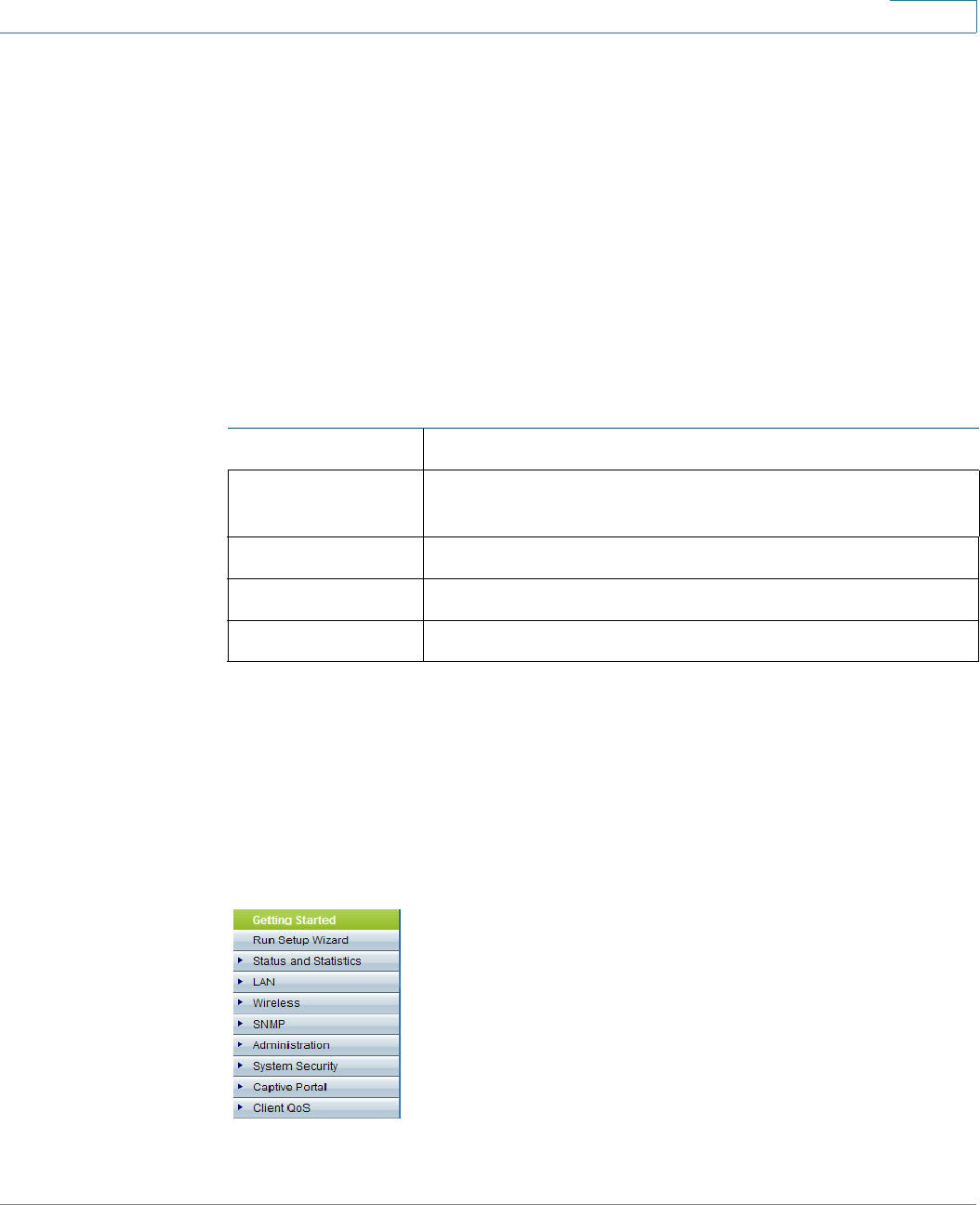
To simplify device configuration through quick navigation, the Getting Started
page provides links for performing common tasks.
/LQNVRQWKH*HWWLQJ6WDUWHG3DJH
&DWHJRU\ /LQN1DPHRQWKH3DJH /LQNHG3DJH
Initial Setup Run Setup Wizard Access Point Startup
Wizard
Configure Radio Settings Radio
Configure Wireless Network Settings Networks
Configure LAN Settings LAN
Run WPS WPS Setup
Device
Status System Summary System Summary
Wireless Client Associations Network Interfaces
Quick
Access Change Account Password User Accounts
Upgrade Device Firmware Upgrade Firmware
Backup/Restore Configuration Download/Backup
Configuration File
Other
Resources Support Cisco AP support site
Forums Cisco Support
Community site
*HWWLQJ6WDUWHG
Window Navigation
Cisco Small Business WAP121 and WAP321 Wireless-N Access Point with PoE 11
REVIEW DRAFT Version 2—CISCO CONFIDENTIAL
:LQGRZ1DYLJDWLRQ
This section describes the features of the web-based AP configuration utility.
$SSOLFDWLRQ+HDGHU
$SSOLFDWLRQ+HDGHU
The Application Header is displayed on every page. It provides the following
buttons:
1DYLJDWLRQ:LQGRZ
1DYLJDWLRQ:LQGRZ
A navigation window is located on the left side of each page. Click a top-level
category to display links to related pages. Links that are preceded by an arrow are
subcategories that expand to display the related page links.
%XWWRQV
%XWWRQ1DPH 'HVFULSWLRQ
(User) The name of the user logged on to the AP. The factory
default user name is FLVFR.
/RJ2XW Click to log out of the web-based AP configuration utility.
$ERXW Click to display the AP type and version number.
+HOS Click to display the online help.

*HWWLQJ6WDUWHG
Window Navigation
Cisco Small Business WAP121 and WAP321 Wireless-N Access Point with PoE 12
REVIEW DRAFT Version 2—CISCO CONFIDENTIAL
0DQDJHPHQW%XWWRQV
0DQDJHPHQW%XWWRQV
The following table describes the commonly used buttons that appear on various
pages in the system.
0DQDJHPHQW%XWWRQV
%XWWRQ1DPH 'HVFULSWLRQ
$GG Click to display the related Add page and add an entry
to a table. Enter the information and click 6DYH to save it
to the Running Configuration and to the Startup
Configuration.
&DQFHO Click to reset changes made on the page.
&OHDU$OO Click to clear all entries in the log table.
'HOHWH Select the entry in the table or list to be deleted and
click 'HOHWH.
'HWDLOV Click to display details associated with the entry
selected on the main page.
(GLW Select an entry and click (GLW to open it for editing. The
Edit page opens, or the relevant fields become editable.
5HIUHVK Click o redisplay the current page with the latest data.
6DYH Click to save the settings to save any configuration
changes to the Running Configuration in RAM and to the
Startup Configuration in nonvolatile memory.
8SGDWH Click to save any configuration changes on part of a
page to the Running Configuration in RAM and to the
Startup Configuration in nonvolatile memory.

3
Cisco Small Business WAP121 and WAP321 Wireless-N Access Point with PoE 13
REVIEW DRAFT Version 2—CISCO CONFIDENTIAL
9LHZLQJ6WDWLVWLFV
This chapter describes how to display WAP121/WAP321 statistics.
It contains the following topics.
•6\VWHP6XPPDU\
•1HWZRUN,QWHUIDFHV
•7UDIILF6WDWLVWLFV
•:RUN*URXS%ULGJH7UDQVPLW5HFHLYH
•$VVRFLDWHG&OLHQWV
•763(&&OLHQW$VVRFLDWLRQV
•5RJXH$3'HWHFWLRQ
•763(&6WDWXVDQG6WDWLVWLFV
•763(&$36WDWLVWLFV
•5$',26WDWLVWLFV
•(PDLO$OHUW6WDWXV
•/RJ

9LHZLQJ6WDWLVWLFV
System Summary
Cisco Small Business WAP121 and WAP321 Wireless-N Access Point with PoE 14
REVIEW DRAFT Version 2—CISCO CONFIDENTIAL
6\VWHP6XPPDU\
The System Summary page displays basic information such as the hardware
model description, software version, and system up time.
To view system information, click 6WDWXVDQG6WDWLVWLFV > 6\VWHP6XPPDU\ in the
navigation window. Or, click 6\VWHP6XPPDU\ under 'HYLFH6WDWXVon the
Getting Started page.
The System Summary page displays the following information:
•3,'9,'—The AP hardware model and version.
•6HULDO1XPEHU—Serial number of the WAP121/WAP321.
•%DVH0$&$GGUHVV—The AP MAC address.
•)LUPZDUH9HUVLRQ—Firmware version number of the active image.
•)LUPZDUH0'&KHFNVXP—The checksum for the active image.
•+RVW1DPH—A name assigned to the device.
•6\VWHP8SWLPH—Time that has elapsed since the last reboot.
•6\VWHP7LPH—Current system time.
The NET_STAT table displays basic information about protocols and services
operating on the AP.
•6HUYLFH—The name of the service, if available.
•3URWRFRO—The underlying transport protocol that the service uses (TCP or
UDP).
•/RFDO,3$GGUHVV—The IP address, if any, of a remote device that is
connected to this service on the switch. A value of All indicates that any IP
address on the device can use this service.
•/RFDO3RUW—The logical port number for the service.
•5HPRWH,3$GGUHVV—The IP address of a remote host, if any, that is using
this service. A value of All indicates that the service is available to all remote
hosts that access the system.
•5HPRWH3RUW—The logical port number of any remote device
communicating with this service.

9LHZLQJ6WDWLVWLFV
Network Interfaces
Cisco Small Business WAP121 and WAP321 Wireless-N Access Point with PoE 15
REVIEW DRAFT Version 2—CISCO CONFIDENTIAL
•&RQQHFWLRQ6WDWH—The state of the service. For UDP, only connections in
the Active state display in the table. In the Active state, a connection is
established between the switch and a client or server. The TCP states are:
-/LVWHQ—The service is listening for connection requests.
-$FWLYH—A connection session is established and packets are being
transmitted and received.
-(VWDEOLVKHG—A connection session is established between the switch
and a server or client, depending on each device’s role with respect to
this protocol.
-7LPH:DLW—The closing sequence has been initiated and the AP is
waiting for a system-defined timeout period (typically 60 seconds)
before closing the connection.
You can click 5HIUHVK to refresh the screen and display the most current
information.
1HWZRUN,QWHUIDFHV
Use the Network Interfaces page to display configuration and status information
about the wired and wireless interfaces. To display this page, click 6WDWXVDQG
6WDWLVWLFV > 1HWZRUN,QWHUIDFHin the navigation window.
The Network Interfaces page displays the following information:
•/$16WDWXV—These settings apply to the internal interface. These include
the MAC Address; VLAN ID; IPv4 Address, subnet mask, and default
gateway; and the IPv6 address and default gateway. The two configured
DNS server IP addresses are also listed. For the WAP321 whether Green
Ethernet mode is enabled also displays.
To change any of these settings, click the Edit link. After you click Edit, you
are redirected to the LAN page. See /$1SDJH for descriptions of
these fields.
•5DGLR6WDWXV—These settings include the Wireless Radio mode (Enabled
or Disabled), the MAC address associated with each radio interface, the
802.11 mode (a/b/g/n), and the channel used by the interface.
To change the wireless settings, click the Edit link. After you click Edit, you
are redirected to the Radio page. See 5DGLRSDJH for descriptions of
these fields.

9LHZLQJ6WDWLVWLFV
Traffic Statistics
Cisco Small Business WAP121 and WAP321 Wireless-N Access Point with PoE 16
REVIEW DRAFT Version 2—CISCO CONFIDENTIAL
You can click 5HIUHVK to refresh the screen and display the most current
information.
7UDIILF6WDWLVWLFV
Use the Traffic Statistics page to view basic information about the AP and a real-
time display of transmit and receive statistics for the Ethernet interface and the
VAPs on both radio interfaces. All transmit and receive statistics reflect the totals
since the AP was last started. If you reboot the AP, these figures indicate transmit
and receive totals since the reboot.
To display this page, click 6WDWXVDQG6WDWLVWLFV>7UDIILF6WDWLVWLFV in the
navigation window.
The Traffic Statistics page displays summary data and statistics for traffic in each
direction.
The following summary traffic statics display:
•1HWZRUN,QWHUIDFH—Name of the Ethernet or VAP interface.
•1DPH66,'—Wireless network name. Also known as the SSID, this
alphanumeric key uniquely identifies a wireless local area network. The
SSID is set on the VAP tab.
•6WDWXV—Whether the interface is up or down.
•0$&$GGUHVV—MAC address for the specified interface. The AP has a
unique MAC address for each interface.
•9/$1,'—Virtual LAN (VLAN) ID. You can use VLANs to establish multiple
internal and guest networks on the same AP. The VLAN ID is set on the VAP
tab. The following statistics display separately for the transmit and receive
traffic:
•7RWDO3 DFNHWV—The total packets sent (in Transmit table) or received (in
Received table) by this AP.
•7RWDO%\WHV—The total bytes sent (in Transmit table) or received (in
Received table) by this AP.
•7RWDO' URSS H G3DFNHW V—The total number of packets sent (in Transmit
table) or received (in Received table) by this AP that were dropped.
•7RWDO'URSSHG%\WHV—The total number of bytes sent (in Transmit table) or
received (in Received table) by this AP that were dropped.

9LHZLQJ6WDWLVWLFV
WorkGroup Bridge Transmit/Receive
Cisco Small Business WAP121 and WAP321 Wireless-N Access Point with PoE 17
REVIEW DRAFT Version 2—CISCO CONFIDENTIAL
•(UURUV—The total number of errors related to sending and receiving data on
this AP.
You can click 5HIUHVK to refresh the screen and display the most current
information.
:RUN*URXS%ULGJH7UDQVPLW5HFHLYH
The WorkGroup Bridge Transmit/Receive page displays packet and byte counts
for traffic between stations on a workgroup bridge. For information on configuring
workgroup bridges, see :RUN*URXS%ULGJHSDJH .
To display this page, click 6WDWXVDQG6WDWLVWLFV>:RUN*URXS%ULGJH in the
navigation window.
The following information displays for each network interface that is configured as
a workgroup bridge interface:
•1HWZRUN,QWHUIDFH—Name of the Ethernet or VAP interface.
•6WDWXVDQG6WDWLVWLFV—Whether the interface is disconnected or is
administratively configured as up or down.
•9/$1,'—Virtual LAN (VLAN) ID. You can use VLANs to establish multiple
internal and guest networks on the same AP. The VLAN ID is set on the VAP
tab.
•1DPH66,'—Wireless network name. Also known as the SSID, this
alphanumeric key uniquely identifies a wireless local area network. The
SSID is set on the VAP tab.
The following additional information displays for the transmit and receive direction
for each workgroup bridge interface:
•7RWDO3 DFNHWV—The total number of packets bridged between the wired
clients in the workgroup bridge and the wireless network.
•7RWDO%\WHV—The total number of bytes bridged between the wired clients
in the workgroup bridge and the wireless network.
You can click 5HIUHVK to refresh the screen and display the most current
information.

9LHZLQJ6WDWLVWLFV
Associated Clients
Cisco Small Business WAP121 and WAP321 Wireless-N Access Point with PoE 18
REVIEW DRAFT Version 2—CISCO CONFIDENTIAL
$VVRFLDWHG&OLHQWV
You can use the Associated Clients page to view the client stations associated
with a particular access point.
To display this page, click 6WDWXVDQG6WDWLVWLFV>$VVRFLDWHG&OLHQWV in the
navigation window.
The associated stations are displayed along with information about packet traffic
transmitted and received for each station.
•7RWDO1XPEHURI$VVRFLDWHG&OLHQWV—The total number of clients currently
associated with the AP.
•1HWZRUN,QWHUIDFH—The VAP the client is associated with. For example, an
entry of wlan0vap2 means the client is associated with the radio interface
(wlan0) and VAP 2.
•6WDWLRQ—The MAC address of the associated wireless client.
•6WDWXV—The Authenticated and Associated Status shows the underlying
IEEE 802.11 authentication and association status, which is present no
matter which type of security the client uses to connect to the AP. This
status does not show IEEE 802.1X authentication or association status.
The following are some points to keep in mind with regard to this field:
-If the AP security mode is None or Static WEP, the authentication and
association status of clients showing on the Client Associations tab will
be in line with what is expected; that is, if a client shows as authenticated
to the AP, it will be able to transmit and receive data. (This is because
Static WEP uses only IEEE 802.11 authentication.)
-If the AP uses IEEE 802.1X or WPA security, however, it is possible for a
client association to show on this tab as authenticated (via the IEEE
802.11 security) but actually not be authenticated to the AP via the
second layer of security.
•)URP6WDWLRQ7R6WDWLRQ—For the From Station, the following counters
indicate the packets or bytes received by the wireless client. For the To
Station, these counters indicate the number of packets and bytes
transmitted from the AP to the wireless client.
-3DFNHWV—Number of packets received (transmitted) from the wireless
client.
-%\WHV—Number of bytes received (transmitted) from the wireless client.

9LHZLQJ6WDWLVWLFV
TSPEC Client Associations
Cisco Small Business WAP121 and WAP321 Wireless-N Access Point with PoE 19
REVIEW DRAFT Version 2—CISCO CONFIDENTIAL
-'URS3DFNHWV—Number of packets dropped after being received
(transmitted).
-'URS%\WHV—Number of bytes that dropped after being received
(transmitted).
-769LRODWH3DFNHWV)URP6WDWLRQ—Number of packets sent from a
client STA to the AP in excess of its active TS uplink bandwidth, or for an
access category requiring admission control to which the client STA has
not been admitted.
-769LRODWH3DFNHWV7R6WDWLRQ—Number of packets sent from the AP
to a client STA in excess of its active TS downlink bandwidth, or for an
access category requiring admission control to which the client STA has
not been admitted.
•8S7LPH—The amount of time the client has been associated with the AP.
You can click 5HIUHVK to refresh the screen and display the most current
information.
763(&&OLHQW$VVRFLDWLRQV
The TSPEC Client Associations page provides information about the TSPEC
client data transmitted and received by this access point. The tables on this page
show voice and video packets transmitted and received by the association, along
with status information.
This page shows a real-time display of the transmit and receive statistics for the
TSPEC clients. All transmit and receive statistics shown are totals since the client
association started.
A TSPEC is a traffic specification that is sent from a QoS-capable wireless client to
an AP requesting a certain amount of network access for the traffic stream (TS) it
represents. A traffic stream is a collection of data packets identified by the
wireless client as belonging to a particular user priority. An example of a voice
traffic stream is a Wi-Fi CERTIFIED telephone handset that marks its codec-
generated data packets as voice priority traffic. An example of a video traffic
stream is a video player application on a wireless laptop that prioritizes a video
conference feed from a corporate server.
To view TSPEC client association statistics, click 6WDWXVDQG6WDWLVWLFV!763(&
&OLHQW$VVRFLDWLRQV in the navigation window.

9LHZLQJ6WDWLVWLFV
TSPEC Client Associations
Cisco Small Business WAP121 and WAP321 Wireless-N Access Point with PoE 20
REVIEW DRAFT Version 2—CISCO CONFIDENTIAL
The following information is provided on the TSPEC Client Associations page.
Status:
•1HWZRUN,QWHUIDFH—Radio interface used by the client.
•66,'—Service set identifier associated with this TS client.
•6WDWLRQ—Client station MAC address.
•76,GHQWLILHU—TSPEC Traffic Session Identifier (range 0-7).
•$FFHVV&DWHJRU\—TS Access Category (voice or video).
•'LUHFWLRQ—Traffic direction for this TS. Direction can be one of the
following:
-uplink
-downlink
-bidirectional
•8VHU3ULRULW\—User Priority (UP) for this TS. The UP is sent with each
packet in the UP portion of the IP header. Typical values are as follows:
-6 or 7 for voice
-4 or 5 for video
The value may differ depending on other priority traffic sessions.
•0HGLXP7LPH—Time (in 32 microsecond per second units) that the TS
traffic occupies the transmission medium.
•([FHVV8VDJH(YHQWV—Number of times the client has exceeded the
medium time established for its TSPEC. Minor, infrequent violations are
ignored.
•9$30$&$GGUHVV—Virtual Access Point MAC address.
Statistics:
•1HWZRUN—Radio interface used by the client.
•6WDWLRQ—Client station MAC address.
•76,GHQWLILHU—TSPEC Traffic Session Identifier (range 0-7).
•$FFHVV&DWHJRU\—TS Access Category (voice or video).

9LHZLQJ6WDWLVWLFV
Rogue AP Detection
Cisco Small Business WAP121 and WAP321 Wireless-N Access Point with PoE 21
REVIEW DRAFT Version 2—CISCO CONFIDENTIAL
•'LUHFWLRQ—The traffic direction for this TS. Direction can be one of the
following:
-uplink
-downlink
-bidirectional
•)URP6WDWLRQ—Shows the number of packets and bytes received from the
wireless client and the number of packets and bytes that were dropped
after being received. The following also display:
-3DFNHWV—Number of packets in excess of an admitted TSPEC.
-%\WHV—Number of packets for which no TSPEC has been established
when admission is required by the AP.
•7R6 WDWLRQ—The number of packets and bytes transmitted from the AP to
the wireless client and the number of packets and bytes that were dropped
upon transmission. The following also display:
-3DFNHWV—Number of packets in excess of an admitted TSPEC.
-%\WHV—Number of packets for which no TSPEC has been established
when admission is required by the AP.
You can click 5HIUHVK to refresh the screen and display the most current
information.
5RJXH$3'HWHFWLRQ
A Rogue AP is an access point that has been installed on a secure network without
explicit authorization from a system administrator. Rogue access points pose a
security threat because anyone with access to the premises can ignorantly or
maliciously install an inexpensive wireless AP that can potentially allow
unauthorized parties to access the network.
The Rogue AP Detection page provides real-time statistics for all APs detected
by the AP in the vicinity of the network. If the AP listed as a rogue is legitimate, you
can add it to the Known AP List.
127( The Detected Rogue AP List and Trusted AP List provide information you can use
to take further action. The AP does not have any control over the APs on the lists
and cannot apply any security policies to APs detected through the RF scan.

9LHZLQJ6WDWLVWLFV
Rogue AP Detection
Cisco Small Business WAP121 and WAP321 Wireless-N Access Point with PoE 22
REVIEW DRAFT Version 2—CISCO CONFIDENTIAL
To view information about other access points on the wireless network, click
6WDWXVDQG6WDWLVWLFV!5RJXH$3'HWHFWLRQin the navigation window.
When AP detection is enabled, the radio will periodically switch from its operating
channel to scan other channels within the same band.
You can click 5HIUHVK to refresh the screen and display the most current
information.
Neighbor AP detection can be enabled and disabled. To enable the radio to collect
information about neighbor APs, click (QDEOH. next to $3'HWHFWLRQIRU5DGLR.
The following information about detected and trusted rogue access points
displays.
•$FWLRQ—If the AP is in the Detected Rogue AP List, you can click *UDQW to
move the AP from the to the Trusted AP List.
If the AP is in the Trusted AP list, you can click 'HOHWH to move the AP to the
Detected Rogue AP List.
127( The Detected Rogue AP List and Trusted AP List provide information.
The WAP121/WAP321 does not have any control over the APs on the list and
cannot apply any security policies to APs detected through the RF scan.
•0$&$GGUHVV—The MAC address of the neighboring AP.
•%HDFRQ,QWHUYDO—The Beacon interval used by this AP.
Beacon frames are transmitted by an AP at regular intervals to announce
the existence of the wireless network. The default behavior is to send a
beacon frame once every 100 milliseconds (or 10 per second).
127( The Beacon Interval is set on the Wireless > Radio page.
•7\SH—The type of device:
-AP indicates the neighboring device is an AP that supports the IEEE
802.11 Wireless Networking Framework in Infrastructure Mode.
-Ad hoc indicates a neighboring station running in Ad hoc Mode. Stations
set to ad hoc mode communicate with each other directly, without the
use of a traditional AP. Ad-hoc mode is an IEEE 802.11 Wireless
Networking Framework also referred to as peer-to-peer mode or an
Independent Basic Service Set (IBSS).
•66,'—The Service Set Identifier (SSID) for the AP.

9LHZLQJ6WDWLVWLFV
Rogue AP Detection
Cisco Small Business WAP121 and WAP321 Wireless-N Access Point with PoE 23
REVIEW DRAFT Version 2—CISCO CONFIDENTIAL
The SSID is an alphanumeric string of up to 32 characters that uniquely
identifies a wireless local area network. It is also referred to as the Network
Name.
127( You can set the SSID on the Wireless > Wireless Network Setup
(VAPs) page.
•3ULYDF\—Indicates whether there is any security on the neighboring
device:
-Off indicates that the Security mode on the neighboring device is set to
None (no security).
-On indicates that the neighboring device has some security in place.
127( You can use the Wireless > Networks page to configure security on
the AP.
•:3$—Whether WPA security is on or off for this AP.
•%DQG—The IEEE 802.11 mode being used on this AP. (For example, IEEE
802.11a, IEEE 802.11b, IEEE 802.11g.)
The number shown indicates the mode according to the following map:
-2.4 indicates IEEE 802.11b, 802.11g, or 802.11n mode (or a combination
of the modes).
-5 indicates IEEE 802.11a or 802.11n mode (or both modes).
•&KDQQHO—The channel on which the AP is currently broadcasting.
The channel defines the portion of the radio spectrum that the radio uses
for transmitting and receiving.
127( You can use the Wireless > Wireless Radio Settings page to set the
channel.
•5DWH—The rate in megabits per second at which this AP is currently
transmitting.
The current rate will always be one of the rates shown in Supported Rates.
•6LJQDO—The strength of the radio signal emitting from this AP. If you hover
the mouse pointer over the bars, a number representing the strength in
decibels (dB) displays.
•%HDFRQV—The total number of beacons received from this AP since it was
first discovered.

9LHZLQJ6WDWLVWLFV
Rogue AP Detection
Cisco Small Business WAP121 and WAP321 Wireless-N Access Point with PoE 24
REVIEW DRAFT Version 2—CISCO CONFIDENTIAL
•/DVW%HDFRQ—The date and time of the last beacon received from this AP.
•5DWHV—Supported and basic (advertised) rate sets for the neighboring AP.
Rates are shown in megabits per second (Mbps).
All Supported Rates are listed, with Basic Rates shown in bold. Rate sets
are configured on the Wireless > Radio page.
To save the Trusted AP List to a file, click 6DYH. The list contains the MAC
addresses of all APs that have been added to the Known AP List. By default, the
filename is Rogue2.cfg. You can use a text editor or Web browser to open the file
and view its contents.
Use the Import AP List from a file feature to import a list of known APs from a
saved list. The list might be acquired from another AP or created from a text file. If
the MAC address of an AP appears in the Trusted AP List, it will not be detected as
a rogue.
To import an AP list from a file, use the following steps:
67(3 Choose whether to replace the existing Trusted AP List or add the entries in the
imported file to the Trusted AP List.
a. Select 5HSODFH to import the list and replace the contents of the Known AP
List.
b. Select 0HUJH to import the list and add the APs in the imported file to the APs
currently displayed in the Known AP List.
67(3 Click %URZVH and choose the file to import.
The file you import must be a plain-text file with a .txt or .cfg extension. Entries in
the file are MAC addresses in hexadecimal format with each octet separated by
colons, for example 00:11:22:33:44:55. Separate entries with a single space. For
the AP to accept the file, it must contain only MAC addresses.
67(3 Click ,PSRUW.
When the import is complete, the screen refreshes and the MAC addresses of the
APs in the imported file appear in the Known AP List.

9LHZLQJ6WDWLVWLFV
TSPEC Status and Statistics
Cisco Small Business WAP121 and WAP321 Wireless-N Access Point with PoE 25
REVIEW DRAFT Version 2—CISCO CONFIDENTIAL
763(&6WDWXVDQG6WDWLVWLFV
The TSPEC Status and Statistics page provides the following:
•Summary information about TSPEC sessions by radio.
•Summary information about TSPEC sessions by VAP.
•Real-time transmit and receive statistics for the radio interface and the
network interface(s).
All of the transmit and receive statistics shown are totals since the AP was last
started. If you reboot the AP, these figures indicate transmit and receive totals
since the reboot.
To view TSPEC status and statistics, click 6WDWXVDQG6WDWLVWLFV!763(&6WDWXV
DQG6WDWLVWLFV in the navigation window.
The TSPEC Status and Statistics page provides the following status information
for the WLAN (Radio) and VAP interfaces:
•1HWZRUN,QWHUIDFH—Name of the Radio or VAP interface.
•$FFHVV&DWHJRU\—Current Access Category associated with this Traffic
Stream (voice or video).
•6WDWXV—Whether the TSPEC session is enabled (up) or not (down) for the
corresponding Access Category.
127( This is a configuration status (does not necessarily represent the
current session activity).
•$FWLYH7UDIILF6WUHDP—Number of currently active TSPEC Traffic Streams
for this radio and Access Category.
•7UDIILF6WUHDP&OLHQWV—Number of Traffic Stream clients associated with
this radio and Access Category.
•0HGLXP7LPH$GPLWWHG—Time (in 32 microsecond per second units)
allocated for this Access Category over the transmission medium to carry
data. This value should be less than or equal to the maximum bandwidth
allowed over the medium for this TS.
•0HGLXP7LPH8QDOORFDWHG—Time (in 32 microsecond per second units) of
unused bandwidth for this Access Category.
The following statistics display separately for the transmit and receive paths on
the wireless radio interface:

9LHZLQJ6WDWLVWLFV
TSPEC AP Statistics
Cisco Small Business WAP121 and WAP321 Wireless-N Access Point with PoE 26
REVIEW DRAFT Version 2—CISCO CONFIDENTIAL
•$FFHVV&DWHJRU\—The Access Category associated with this Traffic
Stream (voice or video).
•7RWDO3 DFNHWV—Total number of TS packets sent (in Transmit table) or
received (in Received table) by this Radio for the specified Access
Category.
•7RWDO%\WHV—Total number of bytes received in the specified access
category.
The following statistics display separately for the transmit and receive paths on
the network interfaces (VAPs):
•7RWDO9RLFH3DFNHWV—Total number of TS voice packets sent (in Transmit
table) or received (in Received table) by this AP for this VAP.
•7RWDO9RLFH%\WHV—Total TS voice bytes sent (in Transmit table) or received
(in Received table) by this AP for this VAP.
•7RWDO9LGHR3DFNHWV—Total number of TS video packets sent (in Transmit
table) or received (in Received table) by this AP for this VAP.
•7RWDO9LGHR%\WHV—Total TS video bytes sent (in Transmit table) or
received (in Received table) by this AP for this VAP.
You can click 5HIUHVK to refresh the screen and display the most current
information.
763(&$36WDWLVWLFV
The TSPEC AP Statistics page provides information on the voice and video Traffic
Streams accepted and rejected by the AP. To view this page, click 6WDWXVDQG
6WDWLVWLFV!763(&$36WDWLVWLFV in the navigation window.
The TSPEC AP Statistics page displays the following information:
•763(&6WDWLVWLFV6XPPDU\IRU9RLFH$&0—The total number of
accepted and the total number of rejected voice traffic streams.
•763(&6WDWLVWLFV6XPPDU\IRU9LGHR$&0—The total number of
accepted and the total number of rejected video traffic streams.
You can click 5HIUHVK to refresh the screen and display the most current
information.

9LHZLQJ6WDWLVWLFV
RADIO Statistics
Cisco Small Business WAP121 and WAP321 Wireless-N Access Point with PoE 27
REVIEW DRAFT Version 2—CISCO CONFIDENTIAL
5$',26WDWLVWLFV
You can use the Radio Statistics page to display packet-level and byte-level
statistics for each wireless radio interface. To view this page, click 6WDWXVDQG
6WDWLVWLFV!5DGLR6WDWLVWLFV in the navigation window.
The following information displays:
•3DFNHWV5HFHLYHG—Total packets received by the AP.
•%\WHV5HFHLYHG—Total bytes received by the AP.
•3DFNHWV7UDQVPLWWHG—Total packets transmitted by the AP.
•%\WHV7UDQVPLWWHG—Total bytes transmitted by the AP.
•3DFNHWV5HFHLYH'URSSHG—Number of packets received by the AP that
were dropped.
•%\WHV5HFHLYH'URSSHG—Number of bytes received by the AP that were
dropped.
•3DFNHWV7UDQVPLW'URSSHG—Number of packets transmitted by the AP
that were dropped.
•%\WHV7UDQVPLW'URSSHG—Number of bytes transmitted by the AP that
were dropped.
•)UDJPHQWV5HFHLYHG—Number of fragmented frames received by the AP.
•)UDJPHQWV7UDQVPLWWHG—Number of fragmented frames sent by the AP.
•0XOWLFDVW)UDPHV5HFHLYHG—Count of MSDU frames received with the
multicast bit set in the destination MAC address.
•0XOWLFDVW)UDPHV7UDQVPLWWHG—Count of successfully transmitted MSDU
frames where the multicast bit is set in the destination MAC address.
•'XSOLFDWH)UDPH&RXQW—Number of times a frame is received and the
Sequence Control field indicates is a duplicate.
•)DLOHG7UDQVPLW&RXQW—Number of times an MSDU is not transmitted
successfully due to transmit attempts exceeding either the short retry limit
or the long retry limit.
•7UDQVPLW5HWU\&RXQW—Number of times an MSDU is successfully
transmitted after one or more retries.

9LHZLQJ6WDWLVWLFV
Email Alert Status
Cisco Small Business WAP121 and WAP321 Wireless-N Access Point with PoE 28
REVIEW DRAFT Version 2—CISCO CONFIDENTIAL
•0XOWLSOH5HWU\&RXQW—Number of times an MSDU is successfully
transmitted after more than one retry.
•5766XFFHVV&RXQW—Count of CTS frames received in response to an
RTS frame.
•576)DLOXUH&RXQW—Count of CTS frames not received in response to an
RTS frame.
•$&.)DLOXUH&RXQW—Count of ACK frames not received when expected.
•)&6(UURU&RXQW—Count of FCS errors detected in a received MPDU
frame.
•)UDPHV7UDQVPLWWHG&RXQW—Count of each successfully transmitted
MSDU.
•:(38QGHFU\SWDEOH&RXQW—Count of encrypted frames received and the
key configuration of the transmitter indicates that the frame should not have
been encrypted or that frame was discarded due to the receiving station
not implementing the privacy option.
You can click 5HIUHVK to refresh the screen and display the most current
information.
(PDLO$OHUW6WDWXV
The Email Alert Status page provides information about the email alerts sent
based on the syslog messages generated in the AP. To view this page, click 6WDWXV
DQG6WDWLVWLFV!(PDLO$OHUW6WDWXVin the navigation window.
This page displays the following fields:
•(PDLO$OHUW6WDWXV—The Email Alert operational status The status is either
Up or Down. The default is Down.
•1XPEHURI(PDLO6HQW—The total number of email sent so far. The range is
an unsigned integer of 32 bits. The default is 0.
•1XPEHURI(PDLO)DLOHG—The total number of email failures so far. The
range is an unsigned integer of 32 bits. The default is 0.
•7LPH/DVW(PDLO6HQW—The day, date, and time time when the last email
was sent.

9LHZLQJ6WDWLVWLFV
Log
Cisco Small Business WAP121 and WAP321 Wireless-N Access Point with PoE 29
REVIEW DRAFT Version 2—CISCO CONFIDENTIAL
/RJ
The Log page displays a list of system events that generated a log entry, such as
login attempts and configuration changes. The log is cleared upon a reboot and
can be cleared by an administrator. Up to 512 events can be displayed. Older
entries are removed from the list as needed to make room for new events.
To view this page, click 6WDWXVDQG6WDWLVWLFV!/RJ6WDWXVin the navigation
window.
This page displays the following fields for each log entry:
•7LPH6WDPS—The system time when the event occurred.
•6HYHULW\—Whether the event occurred due to an error (err) or is
informational (info).
•6HUYLFH—The software component associated with the event.
•'HVFULSWLRQ—A description of the event.
You can click 5HIUHVK to refresh the screen and display the most current
information.
You can click &OHDU$OOto clear all entries from the log.

4
Cisco Small Business WAP121 and WAP321 Wireless-N Access Point with PoE 30
REVIEW DRAFT Version 2—CISCO CONFIDENTIAL
/$16HWWLQJV
This chapter describes how to configure the AP’s port, network, and clock
settings.
It includes the following topics:
•3RUW6HWWLQJV
•/$1
•7LPH6HWWLQJV
3RUW6HWWLQJV
The Port Settings page enables you to view and configure settings for the port
that physically connects the AP to a local area network.
To view and configure LAN settings:
67(3 Click /$1 > 3RUW6HWWLQJV in the navigation area.
The Operational Status area displays the type of port used for the LAN port and
the Link characteristics, as configured in the Administrative Settings area.
67(3 Enable or disable $XWR1HJRWLDWLRQ.
•When enabled, the port will negotiate with its link partner to set the fastest
link speed and duplex mode available.
•When disabled, you can manually configure the port speed and duplex
mode.
67(3 If autonegotiation is disabled, select a 3RUW6SHHG (10Mb/s or 100Mb/s) and the
duplex mode (Half- or Full-duplex).
67(3 Enable or disable *UHHQ(WKHUQHW0RGH.

/$16HWWLQJV
LAN
Cisco Small Business WAP121 and WAP321 Wireless-N Access Point with PoE 31
REVIEW DRAFT Version 2—CISCO CONFIDENTIAL
•When enabled, the port will negotiate with its link partner to set the fastest
link speed and duplex mode available.
•When disabled, you can manually configure the port speed and duplex
mode.
67(3 Click 6DYH. The settings are saved to the Running Configuration and the Startup
Configuration.
/$1
You can use the LAN page to configure settings for the LAN interface, including
static or dynamic IP address assignment and IPv6 functionality.
To configure LAN settings:
67(3 Click /$1 > /$1in the navigation area.
The page displays Global Settings, IPv4 Settings, and IPv6 Settings. The Global
Settings area displays the MAC address of the LAN interface port. This field is
read-only.
67(3 Configure the following Global Settings:
•0DQDJHPHQW9/$1,'{The VLAN associated with the IP address you use
to access the AP. The default management VLAN ID is 1.
This VLAN is also the default untagged VLAN. If you already have a
management VLAN configured on your network with a different VLAN ID, you
must change the VLAN ID of the management VLAN on the AP.
The VLAN VLAN ID range is 1 to 4094.
•3RUW9/$1,'—This VLAN ID is used as the default VLAN for any traffic
received on the LAN port that arrives without a VLAN tag. The AP supports
one untagged VLAN on the LAN interface.
VLAN 1 is the both default untagged VLAN and the default management
VLAN. If you want to segregate management traffic from the untagged VLAN
traffic, set this value to a different value than the management VLAN ID.
The valid VLAN ID range is 1 to 4094.

/$16HWWLQJV
LAN
Cisco Small Business WAP121 and WAP321 Wireless-N Access Point with PoE 32
REVIEW DRAFT Version 2—CISCO CONFIDENTIAL
•$GPLW2QO\9/$17DJJHG)UDPHV—Select to enable the forwarding of
traffic that is received with no VLAN tag. Clear the checkbox if you want
untagged traffic to be forwarded on the VLAN identified by the Port VLAN ID
value.
67(3 Configure the following IPv4 settings:
•&RQQHFWLRQ7\SH—By default, the DHCP client on the WAP121/WAP321
automatically broadcasts requests for network information. If you want to
use a static IP address, you must disable the DHCP client and manually
configure the IP address and other network information.
Select one of the following values from the list:
-'+&3—The AP will acquire its IP address from a DHCP server on the
LAN.
-6WDWLF,3—You will manually assign an IP address to the AP.
•6WDWLF,3$GGUHVV6XEQHW0DVNDQG'HIDXOW*DWHZD\{If you elected to
assign a static IP address, enter the IP information:
•'RPDLQ1DPH6HUYHUV—Select an option from the list:
-'\QDPLF—The AP will acquire DNS server addresses from a DHCP
server on the LAN.
-0DQXDO—You will manually configure one or more DNS server
addresses. Enter up to two IP addresses in the text boxes provided.
67(3 Configure the following IPv6 settings:
•,3Y&RQQHFWLRQ7\SH—How the switch obtains an IPv6 address:
-'+&3Y—The IPv6 address will be assigned by a DHCPv6 server.
-6WDWLF,3Y—You will manually configure the IPv6 address.
•,3Y$GPLQLVWUDWLRQ0RGH—Enables IPv6 management access.
•,3Y$XWR&RQILJXUDWLRQ$GPLQLVWUDWLRQ0RGH—Select to enable IPv6
automatic address configuration on the AP.
When enabled, the AP learns its IPv6 addresses and gateway by processing
the Router Advertisements received on the LAN port. The AP can have
multiple autoconfigured IPv6 addresses.
•6WDWLF,3Y$GGUHVV—The static IPv6 address. The AP can have a static
IPv6 address even if addresses have already been configured automatically.

/$16HWWLQJV
Time Settings
Cisco Small Business WAP121 and WAP321 Wireless-N Access Point with PoE 33
REVIEW DRAFT Version 2—CISCO CONFIDENTIAL
•6WDWLF,3Y$GGUHVV3UHIL[/HQJWK—The prefix length of the static address,
which is an integer in the range of 0–128.
•,3Y$XWRFRQILJXUHG*OREDO$GGUHVVHV—If the AP has been assigned one
or more IPv6 addresses automatically, the addresses are listed.
•,3Y/LQN/RFDO$GGUHVV—The IPv6 address used by the local physical link.
The link local address is not configurable and is assigned by using the IPv6
Neighbor Discovery process.
•'HIDXOW,3Y*DWHZD\—The statically configured default IPv6 gateway.
67(3 Click 6DYH. The settings are saved to the Running Configuration and the Startup
Configuration.
127( Changing some settings might cause the AP to stop and restart system processes.
If this happens, wireless clients will temporarily lose connectivity. We recommend
that you change AP settings when WLAN traffic is low.
7LPH6HWWLQJV
A system clock is used to provide a network-synchronized time-stamping service
for switch software events such as message logs. You can configure the system
clock manually or configure the switch as a Network Time Protocol (NTP) client
that obtains the clock data from a server.
Use the Time Settings page to set the system time manually or to configure the
system to acquire its time settings from a preconfigured NTP server. By default,
the AP is configured to obtain its time from a predefined list of NTP servers.
To display this page, click /$1 > 7LPH6HWWLQJV in the navigation window.
The current system time displays at the top of the page, along with the System
Clock Source option.
To use NTP to have the AP automatically acquire its time settings:
67(3 For the System Clock Source field, select 1HWZRUN7LPH3URWRFRO173.
67(3 Configure the following parameters:

/$16HWWLQJV
Time Settings
Cisco Small Business WAP121 and WAP321 Wireless-N Access Point with PoE 34
REVIEW DRAFT Version 2—CISCO CONFIDENTIAL
•1736HUYHU—Specify the IP address or domain name of an NTP server. A
default NTP server is listed.
•7LPH=RQH{Select the time zone for your location.
67(3 Select $GMXVW7LPHIRU'D\OLJKW6DYLQJV if daylight savings time is applicable to
your time zone. When selected, configure the following fields:
•'D\OLJKW6DYLQJV6WDUW—Select which week, day, month, and time when
daylight savings time starts.
•'D\OLJKW6DYLQJV(QG—Select which week, day, month, and time when
daylight savings time ends.
•'D\OLJKW6DYLQJV2IIVHW{Specify the number of minutes to move the clock
forward when DST begins and backward when it ends.
67(3 Click 6DYH. The changes are saved to the Running Configuration and to the Startup
Configuration.
To manually configure the time settings:
67(3 For the System Clock Source field, select 0DQXDOO\.
67(3 Configure the following parameters:
•6\VWHP'DWH—Select the current month, day, and year date from the drop-
down lists.
•6\VWHP7LPH—Select the current hour and minutes in 24-hour clock format,
such as 22:00:00 for 10 p.m.
•7LPH=RQH{Select the time zone for your location.
67(3 Select $GMXVW7LPHIRU'D\OLJKW6DYLQJV to if daylight savings time is applicable
to your time zone. When selected, configure the following fields:
•'D\OLJKW6DYLQJV6WDUW—Select which week, day, month, and time when
daylight savings time starts.
•'D\OLJKW6DYLQJV(QG—Select which week, day, month, and time when
daylight savings time ends.
•'D\OLJKW6DYLQJV2IIVHWPLQXWHV{Specify the number of minutes to
move the clock forward when DST begins.

/$16HWWLQJV
Time Settings
Cisco Small Business WAP121 and WAP321 Wireless-N Access Point with PoE 35
REVIEW DRAFT Version 2—CISCO CONFIDENTIAL
67(3 Click 6DYH. The changes are saved to the Running Configuration and to the Startup
Configuration.

5
Cisco Small Business WAP121 and WAP321 Wireless-N Access Point with PoE 36
REVIEW DRAFT Version 2—CISCO CONFIDENTIAL
:LUHOHVV6HWWLQJV
This chapter describes how to configure properties of the wireless radio
operation.
It includes the following topics:
•5DGLR
•1HWZRUNV
•6FKHGXOHU
•6FKHGXOHU$VVRFLDWLRQ
•%DQGZLGWK8WLOL]DWLRQ
•0$&)LOWHULQJ
•:'6%ULGJH
•:RUN*URXS%ULGJH
•4R6
•:366HWXS
•:363URFHVV
5DGLR
Radio settings directly control the behavior of the radio in the AP and its
interaction with the physical medium; that is, how and what type of
electromagnetic waves the AP emits.
To configure radio settings:

:LUHOHVV6HWWLQJV
Radio
Cisco Small Business WAP121 and WAP321 Wireless-N Access Point with PoE 37
REVIEW DRAFT Version 2—CISCO CONFIDENTIAL
67(3 Click :LUHOHVV > 5DGLR in the navigation window.
67(3 In the Global Settings area, configure the 763(&9LRODWLRQ,QWHUYDO—The time
interval in seconds for the AP to report (through the system log and SNMP traps)
associated clients that do not adhere to mandatory admission control procedures.
67(3 In the Basic Settings area, configure the following settings:
•5DGLR—Turns on or off the radio interface.
•0$& $GGUHVV—The Media Access Control (MAC) address for the interface.
The MAC address is assigned by the manufacturer and cannot be changed.
•0RGH—The IEEE 802.11 standard and frequency the radio uses.
127( The modes available depend on the country code setting.
Select one of the following modes:
-802.11a—Only 802.11a clients can connect to the AP.
-802.11b/g—802.11b and 802.11g clients can connect to the AP.
-802.11a/n—802.11a clients and 802.11n clients operating in the 5-GHz
frequency can connect to the AP.
-802.11b/g/n (default)—802.11b, 802.11g, and 802.11n clients operating in
the 2.4-GHz frequency can connect to the AP.
-5 GHz 802.11n—Only 802.11n clients operating in the 2.4-GHz frequency
can connect to the AP.
-2.4 GHz 802.11n—Only 802.11n clients operating in the 5-GHz frequency
can connect to the AP.
•&KDQQHO%DQGZLGWK (802.11n modes only)—The 802.11n specification
allows a 40 MHz-wide channel in addition to the legacy 20 MHz channel
available with other modes. The 40 MHz channel enables higher data rates
but leaves fewer channels available for use by other 2.4 GHz and 5 GHz
devices.
Set the field to 20 MHz to restrict the use of the channel bandwidth to a
20 MHz channel.
•3ULPDU\&KDQQHO(802.11n modes with 40 MHz bandwidth only)—A 40 MHz
channel can be considered to consist of two 20 MHz channels that are
contiguous in the frequency domain. These two 20 MHz channels are often

:LUHOHVV6HWWLQJV
Radio
Cisco Small Business WAP121 and WAP321 Wireless-N Access Point with PoE 38
REVIEW DRAFT Version 2—CISCO CONFIDENTIAL
referred to as the Primary and Secondary channels. The Primary Channel is
used for 802.11n clients that support only a 20 MHz channel bandwidth and
for legacy clients.
Select one of the following options:
-Upper—Set the Primary Channel as the upper 20 MHz channel in the
40 MHz band.
-Lower—Set the Primary Channel as the lower 20 MHz channel in the
40 MHz band.
•&KDQQHO—The portion of the radio spectrum the radio uses for transmitting
and receiving.
The range of available channels is determined by the mode of the radio
interface and the country code setting. If you select $XWR for the channel
setting, the AP scans available channels and selects a channel where no
traffic is detected.
Each mode offers a number of channels, depending on how the spectrum is
licensed by national and transnational authorities such as the Federal
Communications Commission (FCC) or the International Telecommunication
Union (ITU-R).
67(3 In the Advanced Settings area, configure the following settings:
•6KRUW*XDUG,QWHUYDO6XSSRUWHG—This field is available only if the selected
radio mode includes 802.11n.
The guard interval is the dead time, in nanoseconds, between OFDM
symbols. The guard interval prevents Inter-Symbol and Inter-Carrier
Interference (ISI, ICI). The 802.11n mode allows for a reduction in this guard
interval from the a and g definition of 800 nanoseconds to 400 nanoseconds.
Reducing the guard interval can yield a 10% improvement in data
throughput.
The client with which the AP is communicating must also support the short
guard interval.
Select one of the following options:
-<HV—The AP transmits data using a 400 ns guard Interval when
communicating with clients that also support the short guard interval.
-1R—The AP transmits data using an 800 ns guard interval.

:LUHOHVV6HWWLQJV
Radio
Cisco Small Business WAP121 and WAP321 Wireless-N Access Point with PoE 39
REVIEW DRAFT Version 2—CISCO CONFIDENTIAL
•3URWHFWLRQ —The protection feature contains rules to guarantee that 802.11
transmissions do not cause interference with legacy stations or applications.
By default, these protection mechanisms are enabled (Auto). With protection
enabled, protection mechanisms will be invoked if legacy devices are within
range of the AP.
You can disable (Off) these protection mechanisms; however, when
protection is off, legacy clients or APs within range can be affected by
802.11n transmissions. Protection is also available when the mode is
802.11b/g. When protection is enabled in this mode, it protects 802.11b
clients and APs from 802.11g transmissions.
127( This setting does not affect the ability of the client to associate with
the AP.
•%HDFRQ,QWHUYDO—The interval between the transmission of beacon frames.
The AP transmits these at regular intervals to announce the existence of the
wireless network. The default behavior is to send a beacon frame once
every 100 milliseconds (or 10 per second).
Enter a value from 20 to 2000 milliseconds.
•'7,03HULRG—The Delivery Traffic Information Map (DTIM period, from 1 to
255 beacons.
The DTIM message is an element included in some Beacon frames. It
indicates which client stations, currently sleeping in low-power mode, have
data buffered on the AP awaiting pick-up.
The DTIM period you specify indicates how often the clients served by this
AP should check for buffered data still on the AP awaiting pickup.
The measurement is in beacons. For example, if you set this field to 1, clients
will check for buffered data on the AP at every beacon. If you set this field to
10, clients will check on every 10th beacon.
•)UDJPHQWDWLRQ7KUHVKROG—The frame size threshold in bytes, from 256 to
2,346.
The fragmentation threshold is a way of limiting the size of packets (frames)
transmitted over the network. If a packet exceeds the fragmentation
threshold you set, the fragmentation function is activated and the packet is
sent as multiple 802.11 frames.
If the packet being transmitted is equal to or less than the threshold,
fragmentation is not used.

:LUHOHVV6HWWLQJV
Radio
Cisco Small Business WAP121 and WAP321 Wireless-N Access Point with PoE 40
REVIEW DRAFT Version 2—CISCO CONFIDENTIAL
Setting the threshold to the largest value (2,346 bytes) effectively disables
fragmentation. Fragmentation plays no role when Aggregation is enabled.
Fragmentation involves more overhead both because of the extra work of
dividing up and reassembling of frames it requires, and because it increases
message traffic on the network. However, fragmentation can help improve
network performance and reliability if properly configured.
Sending smaller frames (by using lower fragmentation threshold) might help
with some interference problems; for example, with microwave ovens.
By default, fragmentation is off. We recommend not using fragmentation
unless you suspect radio interference. The additional headers applied to
each fragment increase the overhead on the network and can greatly reduce
throughput.
•5767KUHVKROG—The Request to Send (RTS) Threshold value, from 0 to
2347.
The RTS threshold indicates the number of octets in an MPDU, below which
an RTS/CTS handshake is not performed.
Changing the RTS threshold can help control traffic flow through the AP,
especially one with a lot of clients. If you specify a low threshold value, RTS
packets will be sent more frequently. This will consume more bandwidth and
reduce the throughput of the packet. On the other hand, sending more RTS
packets can help the network recover from interference or collisions which
might occur on a busy network, or on a network experiencing
electromagnetic interference.
•0D[LPXP$VVRFLDWHG&OLHQWV—The maximum number of stations allowed
to access this AP at any one time.
You can enter a value between 0 and 200.
•7UDQVPLW3RZHU—A percentage value for the transmit power level for this
AP.
The default value, which is 100%, can be more cost-efficient than a lower
percentage since it gives the AP a maximum broadcast range and reduces
the number of APs needed.
To increase capacity of the network, place APs closer together and reduce
the value of the transmit power. This helps reduce overlap and interference
among APs. A lower transmit power setting can also keep your network
more secure because weaker wireless signals are less likely to propagate
outside of the physical location of your network.

:LUHOHVV6HWWLQJV
Radio
Cisco Small Business WAP121 and WAP321 Wireless-N Access Point with PoE 41
REVIEW DRAFT Version 2—CISCO CONFIDENTIAL
•)L[HG0XOWLFDVW5DWH—The multicast traffic transmission rate the AP
supports.
•/HJDF\5DWH6HWV—The transmission rate sets the AP supports and the
basic rate sets the AP advertises:
Rates are expressed in megabits per second.
Supported Rate Sets indicate rates that the AP supports. You can check
multiple rates (click a check box to select or de-select a rate). The AP will
automatically choose the most efficient rate based on factors like error rates
and distance of client stations from the AP.
Basic Rate Sets indicate rates that the AP will advertise to the network for
the purposes of setting up communication with other APs and client stations
on the network. It is generally more efficient to have an AP broadcast a
subset of its supported rate sets.
•0&6'DWD5DWH6HWWLQJV—The Modulation and Coding Scheme (MCS)
index values that the AP advertises. MCS can enhance throughput for
802.11n wireless clients.
Select the check box below the MCS index number to enable it or clear it to
disable the index.
The AP supports MCS indexes 0 to 15. MSC index 15 allows for a maximum
transmission rate of 300 Mbps. If no MCS index is selected, the radio will
operate at MCS index 0, which allows for a maximum transmission rate of 15
Mbps.
The MCS settings can be configured only if the radio mode includes 802.11n
support.
•%URDGFDVW0XOWLFDVW5DWH/LPLWLQJ—Multicast and broadcast rate limiting
can improve overall network performance by limiting the number of packets
transmitted across the network.
By default the Multicast/Broadcast Rate Limiting option is disabled. Until you
enable Multicast/Broadcast Rate Limiting, the following fields will be
disabled.
•5DWH/LPLW—The rate limit for multicast and broadcast traffic. The limit
should be greater than 1, but less than 50 packets per second. Any traffic
that falls below this rate limit will always conform and be transmitted to the
appropriate destination.
The default and maximum rate limit setting is 50 packets per second.

:LUHOHVV6HWWLQJV
Radio
Cisco Small Business WAP121 and WAP321 Wireless-N Access Point with PoE 42
REVIEW DRAFT Version 2—CISCO CONFIDENTIAL
•5DWH/LPLW%XUVW—Setting a rate limit burst determines how much traffic
bursts can be before all traffic exceeds the rate limit. This burst limit allows
intermittent bursts of traffic on a network above the set rate limit.
The default and maximum rate limit burst setting is 75 packets per second.
•763(&0RGH—Regulates the overall TSPEC mode on the AP. The options
are:
-2Q — The AP handles TSPEC requests according to the TSPEC settings
you configure on the Radio page. Use this setting if the AP handles
traffic from QoS-capable devices, such as a Wi-Fi CERTIFIED phone.
-2II — The AP ignores TSPEC requests from client stations. Use this
setting if you do not want to use TSPEC to give QoS-capable devices
priority for time-sensitive traffic.
•763(&9RLFH$&00RGH —Regulates mandatory admission control (ACM)
for the voice access category. The options are:
-2Q — A station is required to send a TSPEC request for bandwidth to the
AP before sending or receiving a voice traffic stream. The AP responds
with the result of the request, which includes the allotted medium time if
the TSPEC was admitted.
-2II — A station can send and receive voice priority traffic without
requiring an admitted TSPEC; the AP ignores voice TSPEC requests
from client stations.
•763(&9RLFH$&0/LPLW —The upper limit on the amount of traffic the AP
attempts to transmit on the wireless medium using a voice AC to gain
access.
•763(&9LGHR$&00RGH —Regulates mandatory admission control for the
video access category. The options are:
-2Q — A station is required to send a TSPEC request for bandwidth to the
AP before sending or receiving a video traffic stream. The AP responds
with the result of the request, which includes the allotted medium time if
the TSPEC was admitted.
-2II — A station can send and receive video priority traffic without
requiring an admitted TSPEC; the AP ignores video TSPEC requests
from client stations.
•763(&9LGHR$&0/LPLW —The upper limit on the amount of traffic the AP
attempts to transmit on the wireless medium using a video AC to gain
access.

:LUHOHVV6HWWLQJV
Networks
Cisco Small Business WAP121 and WAP321 Wireless-N Access Point with PoE 43
REVIEW DRAFT Version 2—CISCO CONFIDENTIAL
•763(&$3,QDFWLYLW\7LPHRXW —The amount of time for an AP to detect an
downlink TS as idle before deleting it.
•763(&6WDWLRQ,QDFWLYLW\7LPHRXW —The amount of time for an AP to detect
an uplink TS as idle before deleting it.
•763(&/HJDF\:004XHXH0DS0RGH —Enables or disables the
intermixing of legacy traffic on queues operating as ACM.
67(3 Click 6DYH. The changes are saved to the Running Configuration and to the Startup
Configuration.
127( Changing some settings might cause the AP to stop and restart system processes.
If this happens, wireless clients will temporarily lose connectivity. We recommend
that you change AP settings when WLAN traffic is low.
1HWZRUNV
Virtual Access Points (VAPs) segment the wireless LAN into multiple broadcast
domains that are the wireless equivalent of Ethernet VLANs. VAPs simulate
multiple APs in one physical AP. Up to 4 VAPs are supported on the WAP121 and
up to 8 VAPs are supported on the WAP321.
Each VAP can be independently enabled or disabled, with the exception of VAP0.
VAP0 is the physical radio interface and remains enabled as long as the radio is
enabled. To disable operation of VAP0, the radio itself must be disabled.
Each VAP is identified by a user-configured Service Set Identifier (SSID). Multiple
VAPs can have the same SSID. Whether the AP broadcasts an SSID is enabled or
disabled independently on each VAP. By default, SSIDs are not broadcast. When
SSID broadcasts are disabled the VAP suppresses responses to probes from
clients.
66,'1DPLQJ&RQYHQWLRQV
The default SSID for VAP0 is ‘ciscosb’. For all other VAPs, the default SSID is
“Virtual Access Point x” where ‘x’ is the VAP number in the range of 1–4 for the
WAP121 and 1–8 for the WAP321. The SSIDs for all VAPs can be configured to
other values.

:LUHOHVV6HWWLQJV
Networks
Cisco Small Business WAP121 and WAP321 Wireless-N Access Point with PoE 44
REVIEW DRAFT Version 2—CISCO CONFIDENTIAL
The SSID can be any alphanumeric, case-sensitive entry from 2 to 32 characters.
The printable characters plus the space (ASCII 0x20) are allowed, but the
following six characters are not:
?, ", $, [, \, ], and +.
The allowable characters are:
ASCII 0x20, 0x21, 0x23, 0x25 through 0x2A, 0x2C through 0x3E, 0x40
through 0x5A, 0x5E through 0x7E.
In addition, the following three characters cannot be the first character:
!, #, and ; (ASCII 0x21, 0x23, and 0x3B, respectively).
Trailing and leading spaces (ASCII 0x20) are not permitted.
127( This means that spaces are allowed within the SSID, but not as the first or last
character, and the period “.” (ASCII 0x2E) is also allowed.
9/$1,'V
Each VAP is associated with a VLAN, which is identified by a VLAN ID (VID). A VID
can be any value from 1 to 4094, inclusive. The WAP121 supports five active
VLANs (four for WLAN plus one management VLAN). The WAP321 supports nine
active VLANs (eight for WLAN plus one management VLAN).
By default, the VID assigned to the management interface for the AP is 1, which is
also the default untagged VID. If the management VID is the same as the VID
assigned to a VAP, then the WLAN clients associated with that VAP can administer
the AP. If needed, an access control list (ACL) can be created to disable
administration from WLAN clients.
&RQILJXULQJ9$3V
To configure VAPs:
67(3 Click :LUHOHVV>1HWZRUNV in the navigation window.
67(3 Select the (QDEOHG check box for the VAP you want to configure.

:LUHOHVV6HWWLQJV
Networks
Cisco Small Business WAP121 and WAP321 Wireless-N Access Point with PoE 45
REVIEW DRAFT Version 2—CISCO CONFIDENTIAL
—Or—
If VAP0 is the only VAP configured on the system, and you want to add a VAP, click
$GG. Then, select the VAP and click (GLW.
127(VAP0 is not editable.
67(3 Configure the parameters:
•9/$1,'—The VID of the VLAN to associate with the VAP.
When a wireless client connects to the AP by using this VAP, the AP tags all
traffic from the wireless client with the VLAN ID you enter in this field unless
you enter the port VLAN ID or use a RADIUS server to assign a wireless
client to a VLAN. The range for the VLAN ID is 1–4094.
You configure the untagged and management VLAN IDs on the Ethernet
Settings page. For more information, see /$1SDJH.
•66,'—A name for the wireless network. The SSID is an alphanumeric string
of up to 32 characters. You can use the same SSID for multiple VAPs, or you
can choose a unique SSID for each VAP.
127(
If you are connected as a wireless client to the same AP that you are
administering, resetting the SSID will cause you to lose connectivity to the
AP. You will need to reconnect to the new SSID after you save this new
setting.
•%URDGFDVW66,'—Enables and disables the broadcast of the SSID.
Specify whether to allow the AP to broadcast the Service Set Identifier
(SSID) in its beacon frames. The Broadcast SSID parameter is enabled by
default. When the VAP does not broadcast its SSID, the network name is not
displayed in the list of available networks on a client station. Instead, the
client must have the exact network name configured in the supplicant before
it is able to connect.
Disabling the broadcast SSID is sufficient to prevent clients from
accidentally connecting to your network, but it will not prevent even the
simplest of attempts by a hacker to connect or monitor unencrypted traffic.
Suppressing the SSID broadcast offers a very minimal level of protection on
an otherwise exposed network (such as a guest network) where the priority
is making it easy for clients to get a connection and where no sensitive
information is available.
•6HFXULW\—The type of authentication required for access to the VAP:
-None

:LUHOHVV6HWWLQJV
Networks
Cisco Small Business WAP121 and WAP321 Wireless-N Access Point with PoE 46
REVIEW DRAFT Version 2—CISCO CONFIDENTIAL
-Static WEP
-Dynamic WEP
-WPA Personal
-WPA Enterprise
If you select a security mode other than None, additional fields appear.
These fields are explained in &RQILJXULQJ6HFXULW\6HWWLQJVSDJH .
•0$&)LOWHULQJ—Whether the stations that can access this VAP are restricted
to a configured global list of MAC addresses. You can select on of the
following types of MAC filtering:
-'LVDEOHG: Do not use MAC filtering.
-/RFDO: Use the MAC Authentication list that you configure on the MAC
Filtering page.
-5$',86: Use the MAC Authentication list on an external RADIUS server.
•&KDQQHO,VRODWLRQ—Enables and disables station isolation.
-When disabled, wireless clients can communicate with one another
normally by sending traffic through the AP.
-When enabled, the AP blocks communication between wireless clients
on the same VAP. The AP still allows data traffic between its wireless
clients and wired devices on the network, across a WDS link, and with
other wireless clients associated with a different VAP, but not among
wireless clients.
•+7735HGLUHFW—Enables or disables the redirecting of wireless clients to a
custom Web page.
When redirect mode is enabled, the user will be redirected to the URL you
specify after the wireless client associates with an AP and the user opens a
Web browser on the client to access the Internet.
The custom Web page must be located on an external Web server and might
contain information such as the company logo and network usage policy.
127( The wireless client is redirected to the external Web server only once
while it is associated with the AP.
•5HGLUHFW85/—The URL where the Web browser is to be redirected after
the wireless client associates with the AP and sends HTTP traffic.

:LUHOHVV6HWWLQJV
Networks
Cisco Small Business WAP121 and WAP321 Wireless-N Access Point with PoE 47
REVIEW DRAFT Version 2—CISCO CONFIDENTIAL
67(3 Click 6DYH. The changes are saved to the Running Configuration and to the Startup
Configuration.
127( Changing some settings might cause the AP to stop and restart system processes.
If this happens, wireless clients will temporarily lose connectivity. We recommend
that you change AP settings when WLAN traffic is low.
127( To delete a VAP, select the VAP and click 'HOHWH.
&RQILJXULQJ6HFXULW\6HWWLQJV
The following sections describe the security settings that you configure,
depending on your selection in the Security list on the Networks page.
1RQH3ODLQWH[W
If you select N
N
one as your security mode, no further options are configurable on
the AP. This mode means that any data transferred to and from the AP is not
encrypted.This security mode can be useful during initial network configuration or
for problem solving, but it is not recommended for regular use on the Internal
network because it is not secure.
6WDWLF:(3
Wired Equivalent Privacy (WEP) is a data encryption protocol for 802.11 wireless
networks. All wireless stations and APs on the network are configured with a static
64-bit (40-bit secret key + 24-bit initialization vector (IV)) or 128-bit (104-bit secret
key + 24-bit IV) Shared Key for data encryption.
Static WEP is not the most secure mode available, but it offers more protection
than setting the security mode to None (Plain-text) as it does prevent an outsider
from easily sniffing out unencrypted wireless traffic.
WEP encrypts data moving across the wireless network based on a static key.
(The encryption algorithm is a stream cipher called RC4.)
The following parameters display for Static WEP configuration:
•7UDQVIHU.H\,QGH[—A key index list. Key indexes 1 through 4 are available.
The default is1.
The Transfer Key Index indicates which WEP key the AP will use to encrypt
the data it transmits.

:LUHOHVV6HWWLQJV
Networks
Cisco Small Business WAP121 and WAP321 Wireless-N Access Point with PoE 48
REVIEW DRAFT Version 2—CISCO CONFIDENTIAL
•.H\/HQJWK—The length of the key. Select one:
-64 bits
-128 bits
•.H\7\SH—The key type. Select one:
-ASCII
-Hex
•:(3.H\V—You can specify up to four WEP keys. In each text box, enter a
string of characters for each key. The keys you enter depend on the key
type selected:
-ASCII—Includes upper and lower case alphabetic letters, the numeric
digits, and special symbols such as @ and #.
-Hex—Includes digits 0 to 9 and the letters A to F.
Use the same number of characters for each key as specified in the
Characters Required field. These are the RC4 WEP keys shared with the
stations using the AP.
Each client station must be configured to use one of these same WEP keys
in the same slot as specified here on the AP.
•Characters Required: The number of characters you enter into the WEP Key
fields is determined by the Key length and Key type you select. For
example, if you use 128-bit ASCII keys, you must enter 26 characters in the
WEP key. The number of characters required updates automatically based
on how you set Key Length and Key Type.
•;$XWKHQWLFDWLRQ—The authentication algorithm defines the method
used to determine whether a client station is allowed to associate with an
AP when static WEP is the security mode.
Specify the authentication algorithm you want to use by choosing one of
the following options:
-2SHQ6\VWHP authentication allows any client station to associate with
the AP whether that client station has the correct WEP key or not. This
algorithm is also used in plaintext, IEEE 802.1X, and WPA modes. When
the authentication algorithm is set to Open System, any client can
associate with the AP.

:LUHOHVV6HWWLQJV
Networks
Cisco Small Business WAP121 and WAP321 Wireless-N Access Point with PoE 49
REVIEW DRAFT Version 2—CISCO CONFIDENTIAL
127( Just because a client station is allowed to
associate
does not
ensure it can exchange traffic with an AP. A station must have the correct
WEP key to be able to successfully access and decrypt data from an AP,
and to transmit readable data to the AP.
-6KDUHG.H\ authentication requires the client station to have the correct
WEP key in order to associate with the AP. When the authentication
algorithm is set to Shared Key, a station with an incorrect WEP key will
not be able to associate with the AP.
-Both 2SHQ6\VWHP and 6KDUHG.H\. When you select both
authentication algorithms, client stations configured to use WEP in
shared key mode must have a valid WEP key in order to associate with
the AP. Also, client stations configured to use WEP as an open system
(shared key mode not enabled) will be able to associate with the AP
even if they do not have the correct WEP key.
Static WEP Rules
If you use Static WEP, the following rules apply:
•All client stations must have the Wireless LAN (WLAN) security set to WEP,
and all clients must have one of the WEP keys specified on the AP in order
to de-code AP-to-station data transmissions.
•The AP must have all keys used by clients for station-to-AP transmit so that
it can de-code the station transmissions.
•The same key must occupy the same slot on all nodes (AP and clients). For
example if the AP defines abc123 key as WEP key 3, then the client stations
must define that same string as WEP key 3.
•Client stations can use different keys to transmit data to the access point.
(Or they can all use the same key, but this is less secure because it means
one station can decrypt the data being sent by another.)
•On some wireless client software, you can configure multiple WEP keys and
define a client station “transfer key index”, and then set the stations to
encrypt the data they transmit using different keys. This ensures that
neighboring APs cannot decode each other’s transmissions.
•You cannot mix 64-bit and 128-bit WEP keys between the access point and
its client stations.

:LUHOHVV6HWWLQJV
Networks
Cisco Small Business WAP121 and WAP321 Wireless-N Access Point with PoE 50
REVIEW DRAFT Version 2—CISCO CONFIDENTIAL
'\QDPLF:(3
Dynamic WEP refers to the combination of 802.1x technology and the Extensible
Authentication Protocol (EAP). With Dynamic WEP security, WEP keys are changed
dynamically.
EAP messages sent over an IEEE 802.11 wireless network using a protocol called
EAP Encapsulation Over LANs (EAPOL). IEEE 802.1X provides dynamically-
generated keys that are periodically refreshed. An RC4 stream cipher is used to
encrypt the frame body and cyclic redundancy checking (CRC) of each 802.11
frame.
This mode requires the use of an external RADIUS server to authenticate users.
The AP requires a RADIUS server that supports EAP, such as the Microsoft Internet
Authentication Server. To work with Windows clients, the authentication server
must support Protected EAP (PEAP) and MSCHAP V2.
You can use any of a variety of authentication methods that the IEEE 802.1X mode
supports, including certificates, Kerberos, and public key authentication. You must
configure the client stations to use the same authentication method the AP uses.
The following parameters display for Dynamic WEP configuration:
•8VH*OREDO5$',866HUYHU6HWWLQJV—By default, each VAP uses the
global RADIUS settings that you define for the AP (see 5$',866HUYHU
SDJH. However, you can configure each VAP to use a different set of
RADIUS servers.
To use the global RADIUS server settings, ensure the check box is selected.
To use a separate RADIUS server for the VAP, clear the check box and enter
the RADIUS server IP address and key in the following fields.
•6HUYHU,3$GGUHVV7\SH—The IP version that the RADIUS server uses.
You can toggle between the address types to configure IPv4 and IPv6
global RADIUS address settings, but the AP contacts only the RADIUS
server or servers for the address type you select in this field.
•6HUYHU,3$GGUHVV or 6HUYHU,3Y$GGUHVV—The address for the primary
RADIUS server for this VAP.
When the first wireless client tries to authenticate with the AP, the AP sends
an authentication request to the primary server. If the primary server
responds to the authentication request, the AP continues to use this
RADIUS server as the primary server, and authentication requests are sent
to the address you specify.

:LUHOHVV6HWWLQJV
Networks
Cisco Small Business WAP121 and WAP321 Wireless-N Access Point with PoE 51
REVIEW DRAFT Version 2—CISCO CONFIDENTIAL
•6HUYHU,3$GGUHVV or 6HUYHU,3Yz—Up to three IPv4 or IPv6 backup
RADIUS server addresses.
If authentication fails with the primary server, each configured backup
server is tried in sequence.
•.H\—The shared secret key that the AP uses to authenticate to the primary
RADIUS server.
You can use up to 63 standard alphanumeric and special characters. The key
is case sensitive and must match the key configured on the RADIUS server.
The text you enter will be displayed as "*" characters.
•.H\z—The RADIUS key associated with the configured backup RADIUS
servers. The server at RADIUS IP Address-1 uses RADIUS Key-1, RADIUS IP
Address-2 uses RADIUS Key-2, and so on.
•(QDEOH5$',86$FFRXQWLQJ—Enables tracking and measuring the
resources a particular user has consumed, such as system time, amount of
data transmitted and received, and so on.
If you enable RADIUS accounting, it is enabled for the primary RADIUS
server and all backup servers.
•$FWLYH6HUYHU—Enables administratively selecting the active RADIUS
server, rather than having the AP attempt to contact each configured server
in sequence and choose the first server that is up.
•%URDGFDVW.H\5HIUHVK5DWH—The interval at which the broadcast (group)
key is refreshed for clients associated to this VAP.
The default is 300. The valid range is 0–86400 seconds. A value of 0
indicates that the broadcast key is not refreshed.
•6HVVLRQ.H\5HIUHVK5DWH—The interval at which the AP refreshes session
(unicast) keys for each client associated to the VAP.
The valid range is 0–86400 seconds. A value of 0 indicates that the
broadcast key is not refreshed.
:3$3HUVRQDO
WPA Personal is a Wi-Fi Alliance IEEE 802.11i standard, which includes AES-CCMP
and TKIP mechanisms. The Personal version of WPA employs a pre-shared key
(PSK) instead of using IEEE 802.1X and EAP as is used in the Enterprise WPA
security mode. The PSK is used for an initial check of credentials only. WPA
Personal is also referred to as WPA-PSK.

:LUHOHVV6HWWLQJV
Networks
Cisco Small Business WAP121 and WAP321 Wireless-N Access Point with PoE 52
REVIEW DRAFT Version 2—CISCO CONFIDENTIAL
This security mode is backwards-compatible for wireless clients that support the
original WPA.
The following parameters display for WPA Personal configuration:
•:3$9HUVLRQV—The types of client stations you want to support:
-:3$—The network has client stations that support the original WPA
and none that support the newer WPA2.
-:3$—All client stations on the network support WPA2. This protocol
version provides the best security per the IEEE 802.11i standard.
If the network has a mix of clients, some of which support WPA2 and others
which support only the original WPA, select both of the check boxes. This
lets both WPA and WPA2 client stations associate and authenticate, but
uses the more robust WPA2 for clients who support it. This WPA
configuration allows more interoperability, at the expense of some security.
•&LSKHU6XLWHV—The cipher suite you want to use:
-TKIP
-CCMP (AES)
You can select either or both. Both TKIP and AES clients can associate with
the AP. WPA clients must have one of the following to be able to associate
with the AP:
-A valid TKIP key
-A valid AES-CCMP key
Clients not configured to use a WPA Personal will not be able to associate
with the AP.
•.H\—The shared secret key for WPA Personal security. Enter a string of at
least 8 characters to a maximum of 63 characters. Acceptable characters
include upper and lower case alphabetic letters, the numeric digits, and
special symbols such as @ and #.
•.H\6WUHQJWK0HWHU—The AP checks the key against complexity criteria
such as how many different types of characters (uppercase, lowercase,
numbers, and special characters) are used and how long the string is. If the
WPA-PSK complexity check feature is enabled, the key will not be
accepted unless it meets the minimum criteria. See :3$36.&RPSOH[LW\
SDJH for information on configuring the complexity check.

:LUHOHVV6HWWLQJV
Networks
Cisco Small Business WAP121 and WAP321 Wireless-N Access Point with PoE 53
REVIEW DRAFT Version 2—CISCO CONFIDENTIAL
•%URDGFDVW.H\5HIUHVK5DWH—The interval at which the broadcast (group)
key is refreshed for clients associated to this VAP (the default is 300). The
valid range is 0–86400 seconds. A value of 0 indicates that the broadcast
key is not refreshed.
:3$(QWHUSULVH
WPA Enterprise with RADIUS is an implementation of the Wi-Fi Alliance IEEE
802.11i standard, which includes CCMP (AES), and TKIP mechanisms. The
Enterprise mode requires the use of a RADIUS server to authenticate users.
This security mode is backwards-compatible with wireless clients that support
the original WPA.
The following parameters display for WPA Enterprise configuration:
•:3$9HUVLRQV—The types of client stations to be supported:
-:3$—If all client stations on the network support the original WPA but
none support the newer WPA2, then select WPA.
-:3$—If all client stations on the network support WPA2, we suggest
using WPA2 which provides the best security per the IEEE 802.11i
standard.
-:3$DQG:3$—If you have a mix of clients, some of which support
WPA2 and others which support only the original WPA, select both WPA
and WPA2. This lets both WPA and WPA2 client stations associate and
authenticate, but uses the more robust WPA2 for clients who support it.
This WPA configuration allows more interoperability, at the expense of
some security.
•(QDEOHSUHDXWKHQWLFDWLRQ—If for WPA Versions you select only WPA2 or
both WPA and WPA2, you can enable pre-authentication for WPA2 clients.
Click (QDEOH pre-authentication if you want WPA2 wireless clients to send
pre-authentication packet. The pre-authentication information will be
relayed from the AP the client is currently using to the target AP. Enabling
this feature can help speed up authentication for roaming clients who
connect to multiple APs.
This option does not apply if you selected WPA for WPA Versions because
the original WPA does not support this feature.
•&LSKHU6XLWHV—The cipher suite you want to use:
-TKIP

:LUHOHVV6HWWLQJV
Networks
Cisco Small Business WAP121 and WAP321 Wireless-N Access Point with PoE 54
REVIEW DRAFT Version 2—CISCO CONFIDENTIAL
-CCMP (AES)
-TKIP and CCMP (AES)
By default both TKIP and CCMP are selected. When both TKIP and CCMP
are selected, client stations configured to use WPA with RADIUS must have
one of the following:
-A valid TKIP RADIUS IP address and RADIUS Key
-A valid CCMP (AES) IP address and RADIUS Key
•8VH*OREDO5$',866HUYHU6HWWLQJV—By default, each VAP uses the
global RADIUS settings that you define for the AP (see 5$',866HUYHU
SDJH. However, you can configure each VAP to use a different set of
RADIUS servers.
To use the global RADIUS server settings, make sure the check box is
selected.
To use a separate RADIUS server for the VAP, clear the check box and enter
the RADIUS server IP address and key in the following fields.
•6HUYHU,3$GGUHVV7\SH—The IP version that the RADIUS server uses.
You can toggle between the address types to configure IPv4 and IPv6
global RADIUS address settings, but the AP contacts only the RADIUS
server or servers for the address type you select in this field.
•6HUYHU,3$GGUHVV or 6HUYHU,3Y$GGUHVV —The address for the primary
RADIUS server for this VAP.
If the IPv4 RADIUS IP Address Type option is selected in the previous field,
enter the IP address of the RADIUS server that all VAPs use by default, for
example 192.168.10.23. If the IPv6 RADIUS IP Address Type option is
selected, enter the IPv6 address of the primary global RADIUS server, for
example 2001:0db8:1234::abcd.
•6HUYHU,3$GGUHVV or 6HUYHU,3Y$GGUHVVz—Up to three IPv4 and/or
IPv6 addresses to use as the backup RADIUS servers for this VAP.The field
label is RADIUS IP Address when the IPv4 RADIUS IP Address Type option
is selected and RADIUS IPv6 Address when the IPv6 RADIUS IP Address
Type option is selected.
If authentication fails with the primary server, each configured backup
server is tried in sequence.

:LUHOHVV6HWWLQJV
Scheduler
Cisco Small Business WAP121 and WAP321 Wireless-N Access Point with PoE 55
REVIEW DRAFT Version 2—CISCO CONFIDENTIAL
•.H\—The RADIUS key is the shared secret key for the global RADIUS
server. You can use up to 63 standard alphanumeric and special characters.
The key is case sensitive, and you must configure the same key on the AP
and on your RADIUS server. The text you enter will be displayed as "*"
characters to prevent others from seeing the RADIUS key as you type.
•.H\z—The RADIUS key associated with the configured backup RADIUS
servers. The server at RADIUS IP Address-1 uses RADIUS Key-1, RADIUS IP
Address-2 uses RADIUS Key-2, and so on.
•(QDEOH5$',86$FFRXQWLQJ—Tracks and measures the resources a
particular user has consumed such as system time, amount of data
transmitted and received, and so on.
If you enable RADIUS accounting, it is enabled for the primary RADIUS
server and all backup servers.
•$FWLYH6HUYHU—Enables administratively selecting the active RADIUS
server, rather than having the AP attempt to contact each configured server
in sequence and choose the first server that is up.
%URDGFDVW.H\5HIUHVK5DWH—The interval at which the broadcast (group)
key is refreshed for clients associated to this VAP.
The default is 300. The valid range is 0–86400 seconds. A value of 0
indicates that the broadcast key is not refreshed.
•6HVVLRQ.H\5HIUHVK5DWH—The interval at which the AP refreshes session
(unicast) keys for each client associated to the VAP.
The valid range is 0–86400 seconds. A value of 0 indicates that the session
key is not refreshed.
6FKHGXOHU
The Radio and VAP Scheduler allows you to configure a rule with a specific time
interval for VAPs or radios to be operational, thereby automating the enabling or
disabling of the VAPs and radio.
One way you can use this feature is to schedule the radio to operate only during
the office working hours in order to achieve security and reduce power
consumption. You can also use the Scheduler to allow access to VAPs for wireless
clients only during specific times of day.

:LUHOHVV6HWWLQJV
Scheduler
Cisco Small Business WAP121 and WAP321 Wireless-N Access Point with PoE 56
REVIEW DRAFT Version 2—CISCO CONFIDENTIAL
The AP supports up to 16 profiles. Only valid rules are added to the profile. Up to
16 rules are grouped together to form a scheduling profile. Periodic time entries
belonging to the same profile cannot overlap.
$GGLQJ6FKHGXOHU3URILOHV
You can create up to 16 scheduler profile names. By default, no profiles are
created.
To view Scheduler status and add a Scheduler profile:
67(3 Click :LUHOHVV > 6FKHGXOHU in the navigation window.
67(3 Ensure that the $GPLQLVWUDWLYH0RGH is enabled. By default it is disabled.
The Scheduler Operational Status area indicates the current operation status of
the Scheduler:
•6WDWXV—The operational status of the Scheduler. The range is Up or Down.
The default is Down.
•5HDVRQ—The reason for the scheduler operational status. Possible values
are:
-IsActive—The scheduler is administratively enabled.
-ConfigDown—Operational status is down because global configuration
is disabled.
-TimeNotSet—Time is set on the AP neither manually nor through NTP.
67(3 To add a profile, enter a profile name in the 6FKHGXOHU3URILOH text box and click
$GG.
The profile name can be up to 32 alphanumeric characters.

:LUHOHVV6HWWLQJV
Scheduler
Cisco Small Business WAP121 and WAP321 Wireless-N Access Point with PoE 57
REVIEW DRAFT Version 2—CISCO CONFIDENTIAL
&RQILJXULQJ6FKHGXOHU5XOHV
You can configure up to 16 rules for a profile. Each rule specifies the start time, end
time and day (or days) of the week the radio or VAP can be operational. The rules
are periodic in nature and are repeated every week. A valid rule must contain all of
the parameters (days of the week, hour, and minute) for the start time and the end
time. Rules cannot conflict; for example, you can configure one rule to start on each
weekday and another to start on each weekend day, but you cannot configure one
rule to begin daily and another rule to begin on weekends.
To configure a rule for a profile:
67(3 Select the profile from the 6HOHFWD3URILOH1DPHlist.
67(3 Click $GG5XOH.
The new rule displays in the rule table.
67(3 Select the checkbox next to the rule name and click (GLW.
67(3 From the 'D\RIWKH:HHNmenu, select the recurring schedule for the rule. You
can configure the rule to occur daily, each weekday, each weekend day (Saturday
and Sunday), or any single day of the week.
67(3 Set the start and end times:
•6WDUW7LPH—The time when the radio or VAP will be operationally enabled.
The time is in HH:MM 24-hour format. The range is <00-24>:<00-59>. The
default is 00:00.
•(QG7LPH—The time when the radio or VAP will be operationally disabled.
The time is in HH:MM 24-hour format. The range is <00-24>:<00-59>. The
default is 00:00.
67(3 Click 6DYH. The changes are saved to the Running Configuration and to the Startup
Configuration.
127( A Scheduler profile must be associated with a radio interface or a VAP interface to
be in effect. See the Scheduler Association page.
127( To delete a rule, select the profile from the 3URILOH1DPHcolumn and click 'HOHWH.

:LUHOHVV6HWWLQJV
Scheduler Association
Cisco Small Business WAP121 and WAP321 Wireless-N Access Point with PoE 58
REVIEW DRAFT Version 2—CISCO CONFIDENTIAL
6FKHGXOHU$VVRFLDWLRQ
The Scheduler profiles need to be associated with the WLAN interface or a VAP
interface to be effective. By default, there are no Scheduler profiles created, hence
no profile is associated to any radio or VAP.
Only one Scheduler profile can be associated with the WLAN interface or each
VAP. A single profile can be associated to multiple VAPs. If the Scheduler profile
associated with a VAP or the WLAN interface is deleted, then the association is
removed.
To associate a Scheduler profile with the WLAN interface or a VAP:
67(3 Click :LUHOHVV > 6FKHGXOHU$VVRFLDWLRQ in the navigation window.
67(3 For the WLAN interface or a VAP, select the profile from the &UHDWHD3URILOH1DPH
list.
67(3 Click 6DYH. The changes are saved to the Running Configuration and to the Startup
Configuration.
%DQGZLGWK8WLOL]DWLRQ
Use the Bandwidth Utilization page to configure how much of the radio bandwidth
can be utilized before the AP stops allowing new client associations. This feature
is disabled by default.
To enable bandwidth utilization:
67(3 Click :LUHOHVV > %DQGZLGWK8WLOL]DWLRQin the navigation window.
67(3 Click (QDEOH for the %DQGZLGWK8WLOL]DWLRQ setting.
67(3 In the 0D[LPXP8WLOL]DWLRQ7KUHVKROG box, enter the percentage of network
bandwidth utilization allowed on the radio before the AP stops accepting new
client associations.
The default is 0, which means that all new associations will be allowed regardless
of the utilization rate.
67(3 Click 6DYH. The changes are saved to the Running Configuration and to the Startup
Configuration.

:LUHOHVV6HWWLQJV
MAC Filtering
Cisco Small Business WAP121 and WAP321 Wireless-N Access Point with PoE 59
REVIEW DRAFT Version 2—CISCO CONFIDENTIAL
127( Changing some settings might cause the AP to stop and restart system processes.
If this happens, wireless clients will temporarily lose connectivity. We recommend
that you change AP settings when WLAN traffic is low.
0$&)LOWHULQJ
Media Access Control (MAC) filtering can be used to exclude or allow only listed
client stations to authenticate with the access point. MAC authentication is
enabled and disabled per VAP on the Networks page. Depending on how the VAP
is configured, the AP may refer to a MAC filter list stored on an external RADlUS
server, or may refer a MAC filter list stored locally on the AP.
&RQILJXULQJD0$&)LOWHU/LVW/RFDOO\RQWKH$3
The MAC Filtering page enables you to configure a local list.
The AP supports one local MAC filter list only; that is, the same list applies to all
VAPs that are enabled to use the local list. The filter can be configured to grant
access only to the MAC addresses on the list, or to deny access only to addresses
on the list.
Up to 512 MAC addresses can be added to the filter list.
To configure MAC filtering:
67(3 Click :LUHOHVV > 0$&)LOWHULQJ in the navigation window.
67(3 Select how the AP uses the filter list:
•Allow only stations in the list. Any station that is not in the Stations List is
denied access to the network through the AP.
•Block all stations in list. Only the stations that appear in the list are denied
access to the network through the AP. All other stations are permitted
access.
127(: The filter setting also applies to the MAC filtering list stored on the
RADIUS server, if one exists.
67(3 In the 0$&$GGUHVV field, enter the MAC address to allow or block and click $GG.

:LUHOHVV6HWWLQJV
WDS Bridge
Cisco Small Business WAP121 and WAP321 Wireless-N Access Point with PoE 60
REVIEW DRAFT Version 2—CISCO CONFIDENTIAL
The MAC Address appears in the 6WDWLRQV/LVW.
67(3 Continue entering MAC addresses until the list is complete, and then click 6DYH.
The changes are saved to the Running Configuration and to the Startup
Configuration.
127(: To remove a MAC Address from the Stations List, select it, then click
5HPRYH.
127(: Changing some settings might cause the AP to stop and restart system
processes. If this happens, wireless clients will temporarily lose connectivity. We
recommend that you change AP settings when WLAN traffic is low.
&RQILJXULQJ0$&$XWKHQWLFDWLRQRQWKH5$',866HUYHU
If one or more VAPs are configured to use a MAC filter stored on a RADIUS
authentication server, you must configure the station list on the RADIUS server. The
format for the list is described in the following table.
:'6%ULGJH
The Wireless Distribution System (WDS) allows you to connect multiple APs. With
WDS, APs communicate with one another without wires in a standardized way.
This capability is critical in providing a seamless experience for roaming clients
and for managing multiple wireless networks. It can also simplify the network
infrastructure by reducing the amount of cabling required. You can configure the
AP in point-to-point or point-to-multipoint bridge mode based on the number of
links to connect.
5$',866HUYHU
$WWULEXWH
'HVFULSWLRQ 9DOXH
User-Name (1) MAC address of the client station. Valid Ethernet MAC
Address.
User-Password (2) A fixed global password used to
lookup a client MAC entry. NOPASSWORD

:LUHOHVV6HWWLQJV
WDS Bridge
Cisco Small Business WAP121 and WAP321 Wireless-N Access Point with PoE 61
REVIEW DRAFT Version 2—CISCO CONFIDENTIAL
In the point-to-point mode, the AP accepts client associations and communicates
with wireless clients and other repeaters. The AP forwards all traffic meant for the
other network over the tunnel that is established between the APs. The bridge
does not add to the hop count. It functions as a simple OSI layer 2 network device.
In the point-to-multipoint bridge mode, one AP acts as the common link between
multiple APs. In this mode, the central AP accepts client associations and
communicates with the clients and other repeaters. All other APs associate only
with the central AP that forwards the packets to the appropriate wireless bridge
for routing purposes.
The AP can also act as a repeater. In this mode, the AP serves as a connection
between two APs that might be too far apart to be within cell range. When acting
as a repeater, the AP does not have a wired connection to the LAN and repeats
signals by using the wireless connection. No special configuration is required for
the AP to function as a repeater, and there are no repeater mode settings. Wireless
clients can still connect to an AP that is operating as a repeater.
Before you configure WDS on the AP, note the following guidelines:
•When using WDS, be sure to configure WDS settings on both APs
participating in the WDS link.
•You can have only one WDS link between any pair of APs. That is, a remote
MAC address may appear only once on the WDS page for a particular AP.
•Both APs participating in a WDS link must be on the same Radio channel
and using the same IEEE 802.11 mode. (See 5DGLRSDJH for information
on configuring the radio mode and channel.)
•When 802.11h is operational, setting up two WDS links can be difficult. See
8VLQJWKHK:LUHOHVV0RGHSDJH .
•If you use WPA encryption on the WDS link VAP0 must use WPA Personal or
WPA Enterprise as the security mode.
To configure a WDS bridge:
67(3 Click :LUHOHVV > :'6%ULGJH in the navigation window.
67(3 Select (QDEOH for 6SDQQLQJ7UHH0RGH. When enabled, STP helps prevent
switching loops. STP is recommended if you configure WDS links.
67(3 Select (QDEOH for :'6,QWHUIDFH.
67(3 Configure the remaining parameters:

:LUHOHVV6HWWLQJV
Work Group Bridge
Cisco Small Business WAP121 and WAP321 Wireless-N Access Point with PoE 62
REVIEW DRAFT Version 2—CISCO CONFIDENTIAL
•5HPRWH0$&$GGUHVV—Specify the MAC address of the destination AP;
that is, the AP on the other end of the WDS link to which data will be sent or
handed-off and from which data will be received.
•(QFU\SWLRQ—The type of encryption to use on the WDS link. The options are
none, WEP, and WPA Personal.
If you are unconcerned about security issues on the WDS link, you may
decide not to set any type of encryption. Alternatively, if you have security
concerns you can choose between Static WEP and WPA Personal. In WPA
Personal mode, the AP uses WPA2-PSK with CCMP (AES) encryption over
the WDS link.
127(: In order to configure WPA Personal on any WDS link, VAP0 must be
configured for WPA Personal or WPA-Enterprise.
See &RQILJXULQJ6HFXULW\6HWWLQJVSDJH for more information about
WEP and WPA Personal security settings.
67(3 Repeat these steps for up to three additional WDS interfaces.
67(3 Click 6DYH. The changes are saved to the Running Configuration and to the Startup
Configuration.
127( Changing some settings might cause the AP to stop and restart system processes.
If this happens, wireless clients will temporarily lose connectivity. We recommend
that you change AP settings when WLAN traffic is low.
:RUN*URXS%ULGJH
The AP Work Group Bridge feature enables the AP to extend the accessibility of a
remote network. In Work Group Bridge mode, the AP acts as a wireless station
(STA) on the wireless LAN. It can bridge traffic between a remote wired network or
associated wireless clients and a wireless LAN that is connected using the Work
Group Bridge mode.
The Work Group Bridge feature enables support for STA-mode and AP-mode
operation simultaneously. The AP can operate in one BSS as an STA device while
operating on another BSS as an AP device. When Work Group Bridge mode is
enabled, then the AP supports only one BSS for wireless clients that associate
with it, and another BSS to which the AP associates as a wireless client.

:LUHOHVV6HWWLQJV
Work Group Bridge
Cisco Small Business WAP121 and WAP321 Wireless-N Access Point with PoE 63
REVIEW DRAFT Version 2—CISCO CONFIDENTIAL
It is recommended that Work Group Bridge mode be used only when the WDS
bridge feature cannot be operational with a peer AP. WDS is a better solution and
is preferred over the Work Group Bridge solution. The Work Group Bridge feature
should be used only when WDS links cannot be established due to hardware
mismatches within an extended service set (ESS). When the Work Group Bridge
feature is enabled, the VAP configurations are not applied; only the Work Group
Bridge configuration is applied.
127( The WDS feature does not work when the Work Group Bridge mode is enabled on
the AP.
In Work Group Bridge mode, the BSS managed by the AP while operating in AP
mode is referred to as the downstream BSS, and associated STAs as downstream
STAs. The BSS managed by the other AP (i.e., the one to which the AP associates
as an STA) is referred to as the upstream BSS, and the other AP is referred as the
upstream AP.
The devices connected to the wired interface of the AP, as well as the
downstream stations associated to the AP’s downstream BSS can access the
network connected by the upstream BSS. To allow the bridging of packets, the
VLAN configuration for the downstream BSS and wired interface should match
that of the upstream BSS.
Work Group Bridge mode can be used as range extender to enable the BSS to
provide access to remote or hard-to-reach networks. A single-radio can be
configured to forward packets from associated STAs to another AP in the same
ESS, without using WDS.
127( Work Group Bridge mode currently supports only IPv4 traffic.
127( Work Group Bridge mode is not supported across a cluster.
To configure Work Group Bridge mode:
67(3 Click :LUHOHVV > :RUN*URXS%ULGJHin the navigation window.
67(3 Select (QDEOH for the :RUN*URXS%ULGJH0RGH.
67(3 Configure the following parameters for the upstream interface and then the
downstream interface:
•66,'—The SSID if the BSS
•%URDGFDVW66,' (downstream only)—Select 2Q if you want the downstream
SSID to be broadcast. SSID Broadcast is off by default.
-1RQH

:LUHOHVV6HWWLQJV
Work Group Bridge
Cisco Small Business WAP121 and WAP321 Wireless-N Access Point with PoE 64
REVIEW DRAFT Version 2—CISCO CONFIDENTIAL
-6WDWLF:(3
-:3$3HUVRQDO
See &RQILJXULQJ6HFXULW\6HWWLQJVSDJH for information about WEP
and WPA Personal security settings.
Configure the upstream BSS with the same SSID and security as advertised
by upstream AP. The upstream BSS will be associated to the upstream AP
with the configured credentials. The AP may obtains its IP address from a
DHCP server on the upstream link. Alternatively, you can assign a static IP
address.
In the downstream direction, clients associate to the downstream BSS.
•6HFXULW\—The type of security to use for authenticating as a client station
on the upstream AP and for authenticating downstream client stations to the
AP.
•0$&)LOWHULQJ—Select one of the following:
-'LVDEOHG—The set of clients in the APs BSS that can access the
upstream network is not restricted to the clients specified in a MAC
address list.
-/RFDO—The set of clients in the APs BSS that can access the upstream
network is restricted to the clients specified in a locally defined MAC
address list.
-5$',86—The set of clients in the APs BSS that can access the upstream
network is restricted to the clients specified in a MAC address list on a
RADIUS server.
If you select Local or RADIUS, see 0$&)LOWHULQJSDJH for instructions
on creating the MAC filter list.
•9/$1,'—The VLAN associated with the BSS.
67(3 Click 6DYH. The changes are saved to the Running Configuration and to the Startup
Configuration.
The associated downstream clients will now have connectivity to the upstream
network.

:LUHOHVV6HWWLQJV
QoS
Cisco Small Business WAP121 and WAP321 Wireless-N Access Point with PoE 65
REVIEW DRAFT Version 2—CISCO CONFIDENTIAL
4R6
The Quality of Service (QoS) settings provide you with the ability to configure
transmission queues for optimized throughput and better performance when
handling differentiated wireless traffic, such as voice-over-IP (VoIP), other types of
audio, video, streaming media, and traditional IP data.
To configure QoS on the AP, you set parameters on the transmission queues for
different types of wireless traffic and specifying minimum and maximum wait
times (through contention windows) for transmission.
AP Enhanced Distributed Channel Access (EDCA) parameters affect traffic flowing
from the AP to the client station.
Station EDCA parameters affect traffic flowing from the client station to the AP.
The default values for the AP and station EDCA. In normal use, these values should
not need to be changed. Changing these values will affect the QoS provided.
To configure AP and Station EDCA parameters:
67(3 Click :LUHOHVV > 4R6in the navigation window.
67(3 Select an option from the ('&$7HPSODWH list:
•:)$'HIDXOWV—Populates the AP and Station EDCA parameters with WiFi
Alliance default values, which are best for general, mixed traffic.
•2SWLPL]HGIRU9RLFH—Populates the AP and Station EDCA parameters with
values that are best for voice traffic.
•&XVWRP—Enables you to choose custom EDCA parameters.
The following four queues are defined for different types of data transmitted from
AP-to-station. If you choose a Custom template, the parameters that define the
queues are configurable; otherwise, they are set to predefined values appropriate
to your selection. The four queues are:
•Data 0 (Voice)—High priority queue, minimum delay. Time-sensitive data
such as VoIP and streaming media are automatically sent to this queue.
•Data 1 (Video)—High priority queue, minimum delay. Time-sensitive video
data is automatically sent to this queue.
•Data 2 (Best Effort)—Medium priority queue, medium throughput and delay.
Most traditional IP data is sent to this queue.

:LUHOHVV6HWWLQJV
QoS
Cisco Small Business WAP121 and WAP321 Wireless-N Access Point with PoE 66
REVIEW DRAFT Version 2—CISCO CONFIDENTIAL
•Data 3 (Background)—Lowest priority queue, high throughput. Bulk data that
requires maximum throughput and is not time-sensitive is sent to this queue
(FTP data, for example).
To configure QoS on the AP:
67(3 Configure the following parameters:
127( that the AP EDCA and Station EDCA parameters are configurable only if
you selected Custom in the previous step.
•$UELWUDWLRQ,QWHU)UDPH6SDFH—A wait time for data frames. The wait time
is measured in slots. Valid values for AIFS are 1 through 255.
•0LQLPXP&RQWHQWLRQ:LQGRZ—An input to the algorithm that determines
the initial random backoff wait time (window) for retry of a transmission.
This value is the upper limit (in milliseconds) of a range from which the initial
random backoff wait time is determined.
The first random number generated will be a number between 0 and the
number specified here.
If the first random backoff wait time expires before the data frame is sent, a
retry counter is incremented and the random backoff value (window) is
doubled. Doubling will continue until the size of the random backoff value
reaches the number defined in the Maximum Contention Window.
Valid values for are 1, 3, 7, 15, 31, 63, 127, 255, 511, or 1024. This value must
be lower than the value for the Maximum Contention Window.
•0D[LPXP&RQWHQWLRQ:LQGRZ—The upper limit (in milliseconds) for the
doubling of the random backoff value. This doubling continues until either the
data frame is sent or the Maximum Contention Window size is reached.
Once the Maximum Contention Window size is reached, retries will continue
until a maximum number of retries allowed is reached.
Valid values are 1, 3, 7, 15, 31, 63, 127, 255, 511, or 1024. This value must be
higher than the value for the Minimum Contention Window.
•0D[LPXP%XUVW (AP only)—An AP EDCA parameter that applies only to
traffic flowing from the AP to the client station.
This value specifies (in milliseconds) the maximum burst length allowed for
packet bursts on the wireless network. A packet burst is a collection of
multiple frames transmitted without header information. The decreased
overhead results in higher throughput and better performance.

:LUHOHVV6HWWLQJV
WPS Setup
Cisco Small Business WAP121 and WAP321 Wireless-N Access Point with PoE 67
REVIEW DRAFT Version 2—CISCO CONFIDENTIAL
Valid values are 0.0 through 999.
•:L)L0XOWL0HGLD:00—Select (QDEOHG to enable Wi-Fi MultiMedia
(WMM) extensions. This is enabled by default. With WMM enabled, QoS
prioritization and coordination of wireless medium access is on. With WMM
enabled, QoS settings on the AP control downstream traffic flowing from the
AP to client station (AP EDCA parameters) and the upstream traffic flowing
from the station to the AP (station EDCA parameters).
Disabling WMM deactivates QoS control of station EDCA parameters on
upstream traffic flowing from the station to the AP. With WMM disabled, you
can still set some parameters on the downstream traffic flowing from the AP
to the client station (AP EDCA parameters).
•7;23/LPLW (Station only)—The TXOP Limit is a station EDCA parameter and
only applies to traffic flowing from the client station to the AP. The
Transmission Opportunity (TXOP) is an interval of time, in milliseconds, when
a WME client station has the right to initiate transmissions onto the wireless
medium (WM) towards the Unified Access Point. The TXOP Limit maximum
value is 65535.
•1R$FNQRZOHGJHPHQW—Select (QDEOHG to specify that the AP should not
acknowledge frames with QosNoAck as the service class value.
•8QVFKHGXOHG$XWRPDWLF3RZHU6DYH'HOLYHU\—Select (QDEOHG to enable
APSD, which is a power management method. APSD is recommended if
VoIP phones access the network through the AP.
67(3 Click 6DYH. The changes are saved to the Running Configuration and to the Startup
Configuration.
127( Changing some settings might cause the AP to stop and restart system processes.
If this happens, wireless clients will temporarily lose connectivity. We recommend
that you change AP settings when WLAN traffic is low.
:366HWXS
This section describes the Wi-Fi Protected Setup (WPS) protocol and its
configuration on the switch. It contains the following subsections:
•:362YHUYLHZ
•&RQILJXULQJ:366HWWLQJV

:LUHOHVV6HWWLQJV
WPS Setup
Cisco Small Business WAP121 and WAP321 Wireless-N Access Point with PoE 68
REVIEW DRAFT Version 2—CISCO CONFIDENTIAL
:362YHUYLHZ
WPS is a standard that enables simple establishment of wireless networks
without compromising network security. It relieves both the wireless client users
and the AP administrators from having to know network names, keys, and various
other cryptographic configuration options.
WPS facilitates network setup by allowing the administrator to use a push button
or PIN mechanism to establish wireless networks, thereby avoiding the manual
entry of network names (SSIDs) and wireless security parameters:
•3XVKEXWWRQ: The WPS button is either on the product or a clickable button
on the user interface.
•3HUVRQDO,GHQWLILFDWLRQ1XPEHU3,1: The PIN either is located on a
product label or can be viewed on product user interface.
WPS maintains network security during these simple steps by requiring both the
users of new client devices and WLAN administrators to either have physical
access to their respective devices or secure remote access to these devices.
8VDJH6FHQDULRV
Typical scenarios for using WPS include the following:
•A user wishes to enroll a client station on a WPS-enabled WLAN. (The
enrolling client device may detect the network, and prompt the user to
enroll, although this is not necessary.) The user triggers the enrollment by
pushing a button on the device. The AP's administrator then pushes a button
on the AP. During a brief exchange of WPS protocol messages, the AP
supplies the new client with a new security configuration via the Extensible
Authentication Protocol (EAP). The two devices disassociate, and then
reassociate and authenticate with the new settings.
•A user wishes to enroll a client station on a WPS-enabled WLAN by
supplying the AP administrator with the PIN of the client device. The
administrator enters this PIN on the UI of the AP and triggers the device
enrollment. The new enrollee and the AP exchange WPS messages,
including a new security configuration, disassociate, reassociate, and
authenticate.
•An AP administrator purchases a new AP that has been certified by the
Wi-Fi Alliance to be compliant with WPS version 2.0, and wishes to add the
AP to an existing (wired or wireless) network. The administrator turns on the
AP, and then accesses a network host that supports the WPS registration
protocol. The administrator enters the AP device’s pin on the UI of this

:LUHOHVV6HWWLQJV
WPS Setup
Cisco Small Business WAP121 and WAP321 Wireless-N Access Point with PoE 69
REVIEW DRAFT Version 2—CISCO CONFIDENTIAL
"external registrar," and triggers the WPS registration process at this UI. (On
a wired LAN, the WPS protocol messages are transported via the Universal
Plug and Play, or UPnP, protocol.) The host registers the AP as a new
network device and configures the AP with new security settings.
•An AP administrator has just added a new AP to an existing (wireless or
wired) network via WPS, and wishes to grant network access to a new
client device. The device is enrolled through either the "PIN" or "push button
control (PBC)" methods described above, but this time the device enrolls
with the external registrar, with the AP acting solely as a proxy.
•A wireless device that does not support WPS must join the WPS-enabled
WLAN. The administrator, who cannot use WPS in this case, instead
manually configures the device with the SSID, public shared key, and
cryptography modes of the WPS-enabled AP. The device joins the network.
The PIN is either an eight-digit number that uses its last digit as a checksum value,
or a four-digit number with no checksum. Each of these numbers may contain
leading zeroes.
:365ROHV
The WPS standard assigns specific roles to the various components in its
architecture:
•(QUROOHH—A device that can join the wireless network.
•$3—A device that provides wireless access to the network.
•5HJLVWUDU—An entity that issues security credentials to enrollees and
configures APs.
The WAP121 can act as an AP and supports an internal registrar. It does not
function as a enrollee.
(QDEOLQJDQGGLVDEOLQJ:36RQD9$3
The administrator can enable or disable WPS on only one VAP. WPS is operational
only if this VAP meets the following conditions:
•The AP is configured to broadcast the VAP SSID.
•MAC address filtering is disabled on the VAP.
•WEP encryption is disabled on the VAP.

:LUHOHVV6HWWLQJV
WPS Setup
Cisco Small Business WAP121 and WAP321 Wireless-N Access Point with PoE 70
REVIEW DRAFT Version 2—CISCO CONFIDENTIAL
•The VAP is configured to use either WPA-Personal security or none. If
WPA2-PSK encryption mode is enabled, then an valid pre-shared key (PSK)
must be configured and CCMP (AES) encryption must be enabled.
•The VAP is operationally enabled.
WPS is operationally disabled on the VAP if any of these conditions are not met.
127( Disabling WPS on a VAP does not cause disassociation of any clients previously
authenticated via WPS on that VAP
([WHUQDODQG,QWHUQDO5HJLVWUDWLRQ
It is not necessary for the WAP121 itself to handle the registration of clients on the
network. The AP can either use its internal registrar, or act as a proxy for an
external registrar. The external registrar may be accessed either via the wired or
wireless LAN. An external registrar may also configure the SSID, encryption mode,
and public shared key of a WPS-enabled BSS. This capability is very useful for
"out-of-box" deployments; that is, when an administrator simply attaches a new AP
to a LAN for the first time.
If the AP is using an internal registrar, it enrolls new clients using the configuration
of the VAP associated with the WPS service, whether this configuration was
configured directly on the AP or acquired by an external registrar through WPS.
&OLHQW(QUROOPHQW
Push-button Control
The AP enrolls 802.11 clients via WPS by one of two methods: the push-button
control (PBC) method, or the personal identification number (PIN) method.
Using the PBC method, when the user of a prospective client pushes a button on
the enrolling device, the administrator of the AP with an enabled internal registrar
pushes a similar (hardware or software) button. This sequence begins enrollment
process, and the client device joins the network. Although the WAP121 does not
support an actual hardware button, it allows the administrator to initiate the
enrollment for a particular VAP using a “software button” in the web-based AP
configuration utility.
127( There is no defined order in which the buttons on the client device and AP must be
pressed. Either device can initiate the enrollment. However, if the software button
on the AP is pressed, and no client attempts to enroll after 120 seconds, the AP
terminates the pending WPS enrollment transaction.