Sercomm WAP121 Wireless-N Access Point with Power over Ethernet User Manual
Sercomm Corporation Wireless-N Access Point with Power over Ethernet
Sercomm >
Contents
- 1. User manual 1 of 4
- 2. User manual 2 of 4
- 3. User manual 3 of 4
- 4. User manual 4 of 4
User manual 1 of 4
![2Cisco Small Business WAP121 and WAP321 Wireless-N Access Point with PoE 7REVIEW DRAFT Version 2—CISCO CONFIDENTIAL*HWWLQJ6WDUWHGThis chapter provides an introduction to the web-based access point (AP) configuration utility, and includes the following topics:•6WDUWLQJWKH:HEEDVHG$3&RQILJXUDWLRQ8WLOLW\•8VLQJWKH$FFHVV3RLQW6HWXS:L]DUG•*HWWLQJ6WDUWHG•:LQGRZ1DYLJDWLRQ6WDUWLQJWKH:HEEDVHG$3&RQILJXUDWLRQ8WLOLW\This section describes how to navigate the AP configuration utility.Browsers have the following restrictions:•If you are using Internet Explorer 6, you cannot directly use an IPv6 address to access the AP. You can, however, use the DNS (Domain Name System) server to create a domain name that contains the IPv6 address, and then use that domain name in the address bar in place of the IPv6 address.•To use Internet Explorer 8, open a browser window and configure the following settings:Click 7RROV!,QWHUQHW2SWLRQV and then select the 6HFXULW\ tab. Select /RFDO,QWUDQHW and click 6LWHV. Click $GYDQFHG and then click $GG. Add the intranet address of the AP (http://<ip-address>) to the local intranet zone. The IP address can also be specified as the subnet IP address, so that all addresses in the subnet are added to the local intranet zone.•If you have multiple IPv6 interfaces on your management station, use the IPv6 global address instead of IPv6 link local address to access the AP from your browser.](https://usermanual.wiki/Sercomm/WAP121.User-manual-1-of-4/User-Guide-1592039-Page-7.png)
![*HWWLQJ6WDUWHGStarting the Web-based AP Configuration UtilityCisco Small Business WAP121 and WAP321 Wireless-N Access Point with PoE 8REVIEW DRAFT Version 2—CISCO CONFIDENTIAL/DXQFKLQJWKH8WLOLW\To open the web-based AP configuration utility:67(3 Open a Web browser.67(3 Enter the IP address of the AP you are configuring in the address bar on the browser, and then press Enter. The Login page opens./RJJLQJ,QTo log in to the web-based AP configuration utility:67(3 Enter the user name and password. The factory default user name is FLVFR and the default password is FLVFR.67(3 If this is the first time that you logged on with the default user name (FLVFR) and the default password (FLVFR) or your password has expired, the Change Admin Password page opens. Enter the new password and confirm it, click $SSO\, and then click &ORVH. The new password is saved. Then, enter the user name FLVFR and the new password on the Login page.67(3 Click /RJLQ.When the login attempt is successful, the Access Point Startup Wizard page opens.If you entered an incorrect user name or password, an error message is displayed and the Login page remains displayed on the screen.See 8VLQJWKH$FFHVV3RLQW6HWXS:L]DUGSDJH for instructions on using the wizard./RJJLQJ2XWBy default, the application logs out after five minutes of inactivity. See +773+77366HUYLFH for instructions on changing the default timeout period.To logout, click /RJRXW in the top right corner of any page.](https://usermanual.wiki/Sercomm/WAP121.User-manual-1-of-4/User-Guide-1592039-Page-8.png)
![*HWWLQJ6WDUWHGUsing the Access Point Setup WizardCisco Small Business WAP121 and WAP321 Wireless-N Access Point with PoE 9REVIEW DRAFT Version 2—CISCO CONFIDENTIAL8VLQJWKH$FFHVV3RLQW6HWXS:L]DUGThe first time you log into the AP (or after it has been reset to the factory default settings), the Access Point Startup Wizard displays to help you perform initial configuration. Follow these steps to complete the wizard:127( If you click Cancel to bypass the Wizard, the Change Password page displays. You can then change the default password for logging in. For all other settings, the factory default configuration will apply.67(3 Click 1H[W. The Wizard displays the first of several Configuration windows, the Access Point Setup Wizard—IP Address window.67(3 Configure the system to receive its IP information from a DHCP server, or specify this information manually. For a description of these fields, see /$1SDJH.67(3 Click 1H[W. The Access Point Setup Wizard—Time Settings window displays.67(3 Select your time zone, and then configure the system time manually or set the AP to get its time from an NTP server. For a description of these options, see 7LPH6HWWLQJVSDJH.67(3 Click 1H[W. The Wizard displays the first of four security windows, the Access Point Setup Wizard—Device Password window.67(3 Enter a 1HZ3DVVZRUG and enter it again in the &RQILUP3DVVZRUG text box. For more information about passwords, see 8VHU$FFRXQWVSDJH.67(3 Click 1H[W. The Wizard displays the second of four security windows, the Access Point Setup Wizard—Network Name window.67(3 Enter a 1HWZRUN1DPH. This name serves as the SSID for the default wireless network.67(3 Click 1H[W. The Wizard displays the third of four security windows, the Access Point Setup Wizard—Wireless Security window.67(3 Choose a security type. For a description of these options, see 6\VWHP6HFXULW\SDJH .67(3 Click 1H[W. The Wizard displays the Access Point Setup Wizard—Summarywindow.67(3 Review the settings you configured. If they are correct, click 6XEPLW. Or, click %DFNto reconfigure one or more settings. If you click &DQFHO, all settings are returned to the previous values.](https://usermanual.wiki/Sercomm/WAP121.User-manual-1-of-4/User-Guide-1592039-Page-9.png)

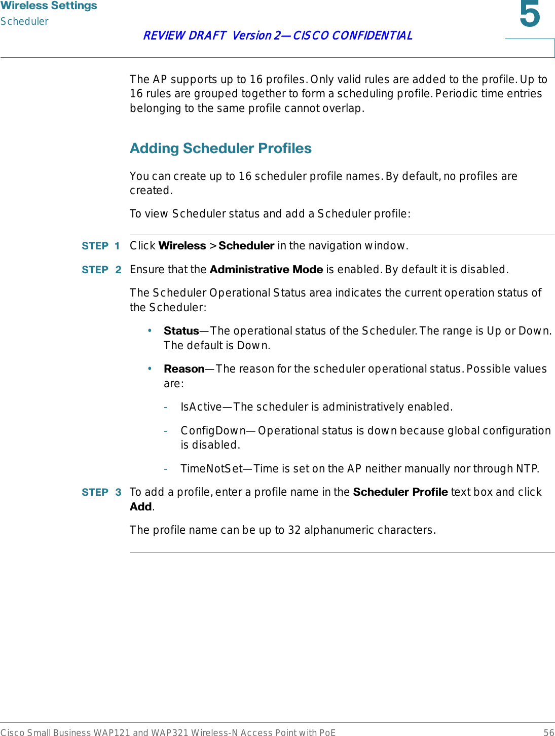
![5Cisco Small Business WAP121 and WAP321 Wireless-N Access Point with PoE 36REVIEW DRAFT Version 2—CISCO CONFIDENTIAL:LUHOHVV6HWWLQJVThis chapter describes how to configure properties of the wireless radio operation.It includes the following topics:•5DGLR•1HWZRUNV•6FKHGXOHU•6FKHGXOHU$VVRFLDWLRQ•%DQGZLGWK8WLOL]DWLRQ•0$&)LOWHULQJ•:'6%ULGJH•:RUN*URXS%ULGJH•4R6•:366HWXS•:363URFHVV5DGLRRadio settings directly control the behavior of the radio in the AP and its interaction with the physical medium; that is, how and what type of electromagnetic waves the AP emits.To configure radio settings:](https://usermanual.wiki/Sercomm/WAP121.User-manual-1-of-4/User-Guide-1592039-Page-36.png)
![:LUHOHVV6HWWLQJVNetworksCisco Small Business WAP121 and WAP321 Wireless-N Access Point with PoE 44REVIEW DRAFT Version 2—CISCO CONFIDENTIALThe SSID can be any alphanumeric, case-sensitive entry from 2 to 32 characters. The printable characters plus the space (ASCII 0x20) are allowed, but the following six characters are not: ?, ", $, [, \, ], and +. The allowable characters are: ASCII 0x20, 0x21, 0x23, 0x25 through 0x2A, 0x2C through 0x3E, 0x40 through 0x5A, 0x5E through 0x7E. In addition, the following three characters cannot be the first character: !, #, and ; (ASCII 0x21, 0x23, and 0x3B, respectively). Trailing and leading spaces (ASCII 0x20) are not permitted.127( This means that spaces are allowed within the SSID, but not as the first or last character, and the period “.” (ASCII 0x2E) is also allowed.9/$1,'VEach VAP is associated with a VLAN, which is identified by a VLAN ID (VID). A VID can be any value from 1 to 4094, inclusive. The WAP121 supports five active VLANs (four for WLAN plus one management VLAN). The WAP321 supports nine active VLANs (eight for WLAN plus one management VLAN).By default, the VID assigned to the management interface for the AP is 1, which is also the default untagged VID. If the management VID is the same as the VID assigned to a VAP, then the WLAN clients associated with that VAP can administer the AP. If needed, an access control list (ACL) can be created to disable administration from WLAN clients.&RQILJXULQJ9$3VTo configure VAPs:67(3 Click :LUHOHVV>1HWZRUNV in the navigation window.67(3 Select the (QDEOHG check box for the VAP you want to configure.](https://usermanual.wiki/Sercomm/WAP121.User-manual-1-of-4/User-Guide-1592039-Page-44.png)

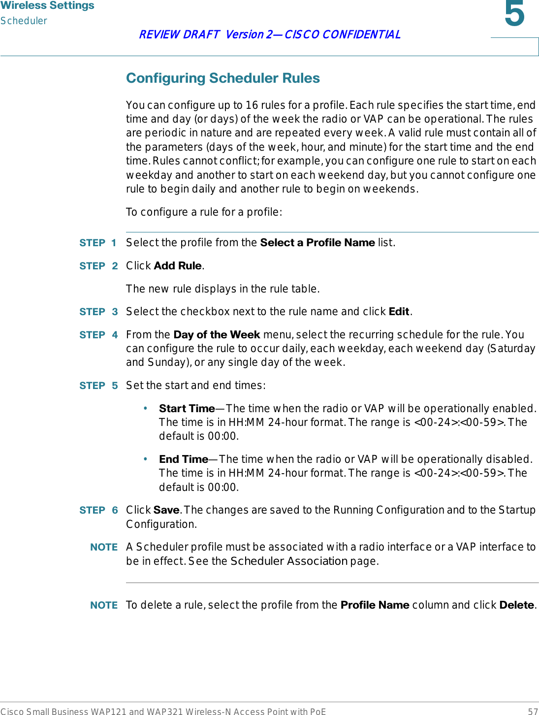
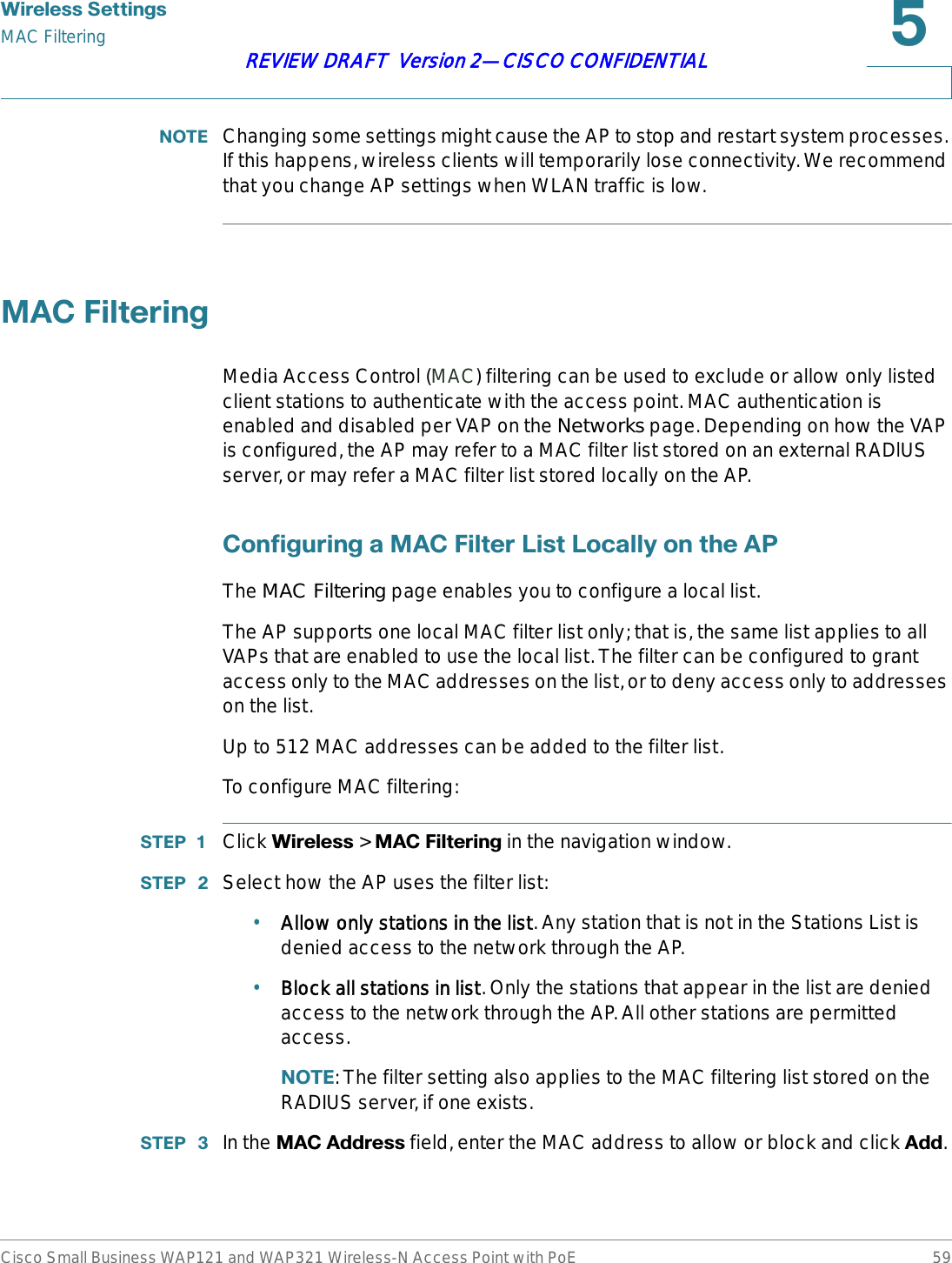
![:LUHOHVV6HWWLQJVScheduler AssociationCisco Small Business WAP121 and WAP321 Wireless-N Access Point with PoE 58REVIEW DRAFT Version 2—CISCO CONFIDENTIAL6FKHGXOHU$VVRFLDWLRQThe Scheduler profiles need to be associated with the WLAN interface or a VAP interface to be effective. By default, there are no Scheduler profiles created, hence no profile is associated to any radio or VAP. Only one Scheduler profile can be associated with the WLAN interface or each VAP. A single profile can be associated to multiple VAPs. If the Scheduler profile associated with a VAP or the WLAN interface is deleted, then the association is removed.To associate a Scheduler profile with the WLAN interface or a VAP:67(3 Click :LUHOHVV > 6FKHGXOHU$VVRFLDWLRQ in the navigation window.67(3 For the WLAN interface or a VAP, select the profile from the &UHDWHD3URILOH1DPHlist.67(3 Click 6DYH. The changes are saved to the Running Configuration and to the Startup Configuration.%DQGZLGWK8WLOL]DWLRQUse the Bandwidth Utilization page to configure how much of the radio bandwidth can be utilized before the AP stops allowing new client associations. This feature is disabled by default.To enable bandwidth utilization:67(3 Click :LUHOHVV > %DQGZLGWK8WLOL]DWLRQin the navigation window.67(3 Click (QDEOH for the %DQGZLGWK8WLOL]DWLRQ setting. 67(3 In the 0D[LPXP8WLOL]DWLRQ7KUHVKROG box, enter the percentage of network bandwidth utilization allowed on the radio before the AP stops accepting new client associations.The default is 0, which means that all new associations will be allowed regardless of the utilization rate.67(3 Click 6DYH. The changes are saved to the Running Configuration and to the Startup Configuration.](https://usermanual.wiki/Sercomm/WAP121.User-manual-1-of-4/User-Guide-1592039-Page-58.png)
![:LUHOHVV6HWWLQJVQoSCisco Small Business WAP121 and WAP321 Wireless-N Access Point with PoE 65REVIEW DRAFT Version 2—CISCO CONFIDENTIAL4R6The Quality of Service (QoS) settings provide you with the ability to configure transmission queues for optimized throughput and better performance when handling differentiated wireless traffic, such as voice-over-IP (VoIP), other types of audio, video, streaming media, and traditional IP data.To configure QoS on the AP, you set parameters on the transmission queues for different types of wireless traffic and specifying minimum and maximum wait times (through contention windows) for transmission.AP Enhanced Distributed Channel Access (EDCA) parameters affect traffic flowing from the AP to the client station.Station EDCA parameters affect traffic flowing from the client station to the AP.The default values for the AP and station EDCA. In normal use, these values should not need to be changed. Changing these values will affect the QoS provided.To configure AP and Station EDCA parameters:67(3 Click :LUHOHVV > 4R6in the navigation window.67(3 Select an option from the ('&$7HPSODWH list:•:)$'HIDXOWV—Populates the AP and Station EDCA parameters with WiFi Alliance default values, which are best for general, mixed traffic.•2SWLPL]HGIRU9RLFH—Populates the AP and Station EDCA parameters with values that are best for voice traffic.•&XVWRP—Enables you to choose custom EDCA parameters.The following four queues are defined for different types of data transmitted from AP-to-station. If you choose a Custom template, the parameters that define the queues are configurable; otherwise, they are set to predefined values appropriate to your selection. The four queues are:•Data 0 (Voice)—High priority queue, minimum delay. Time-sensitive data such as VoIP and streaming media are automatically sent to this queue.•Data 1 (Video)—High priority queue, minimum delay. Time-sensitive video data is automatically sent to this queue.•Data 2 (Best Effort)—Medium priority queue, medium throughput and delay. Most traditional IP data is sent to this queue.](https://usermanual.wiki/Sercomm/WAP121.User-manual-1-of-4/User-Guide-1592039-Page-65.png)