Sercomm WAP121 Wireless-N Access Point with Power over Ethernet User Manual
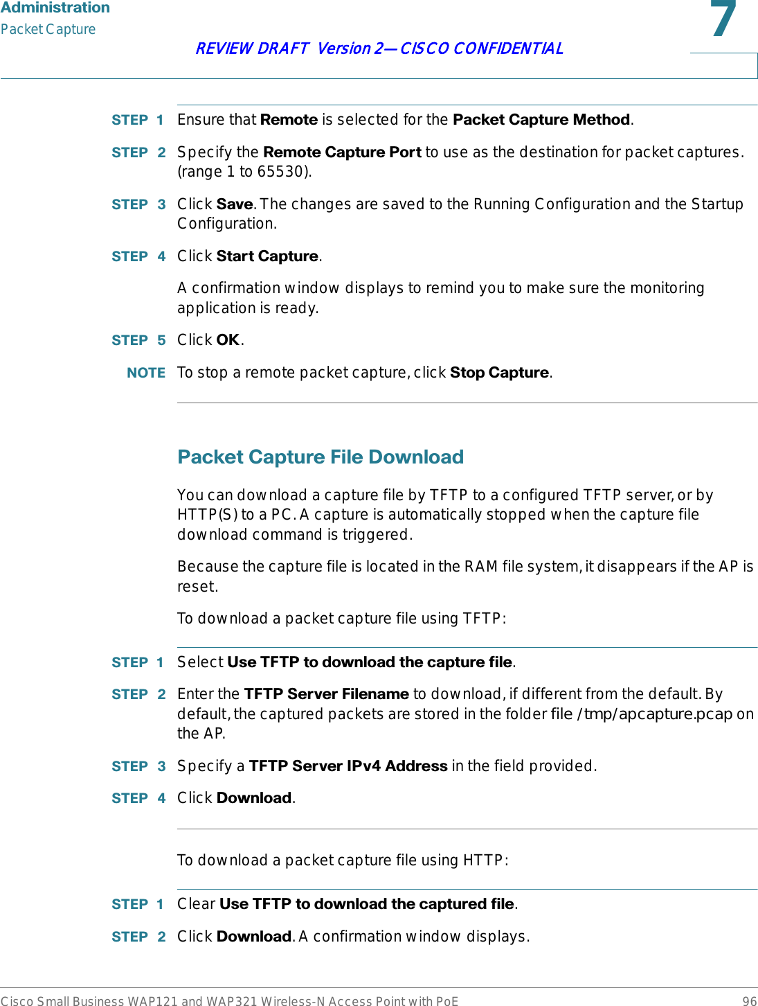
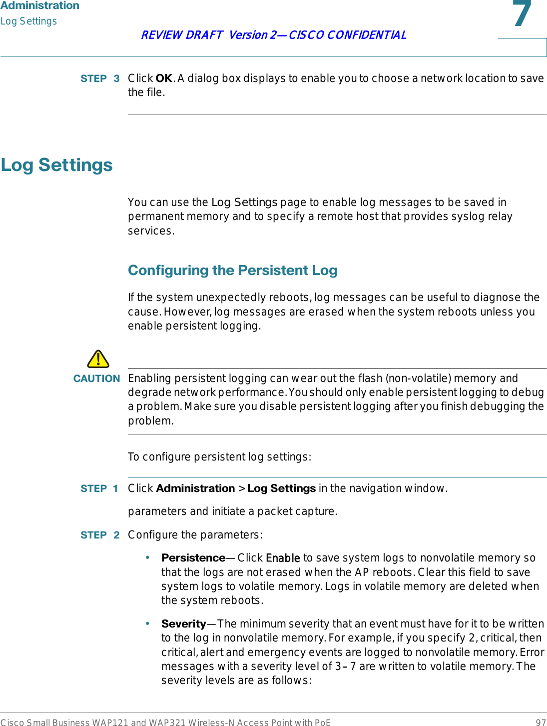
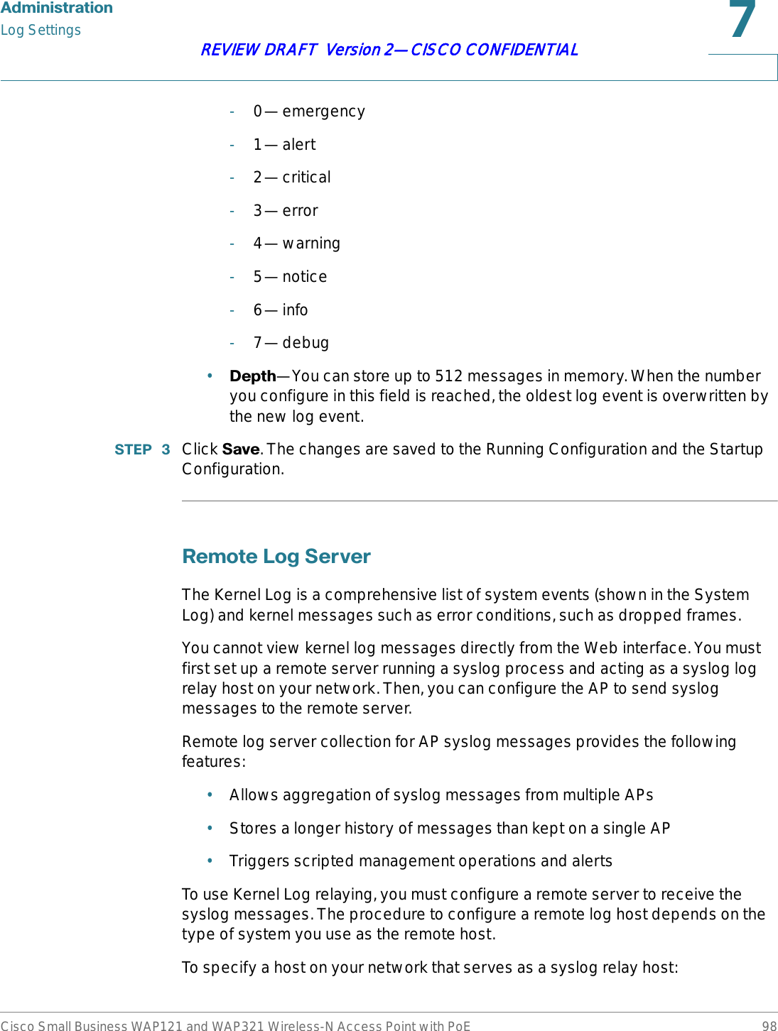
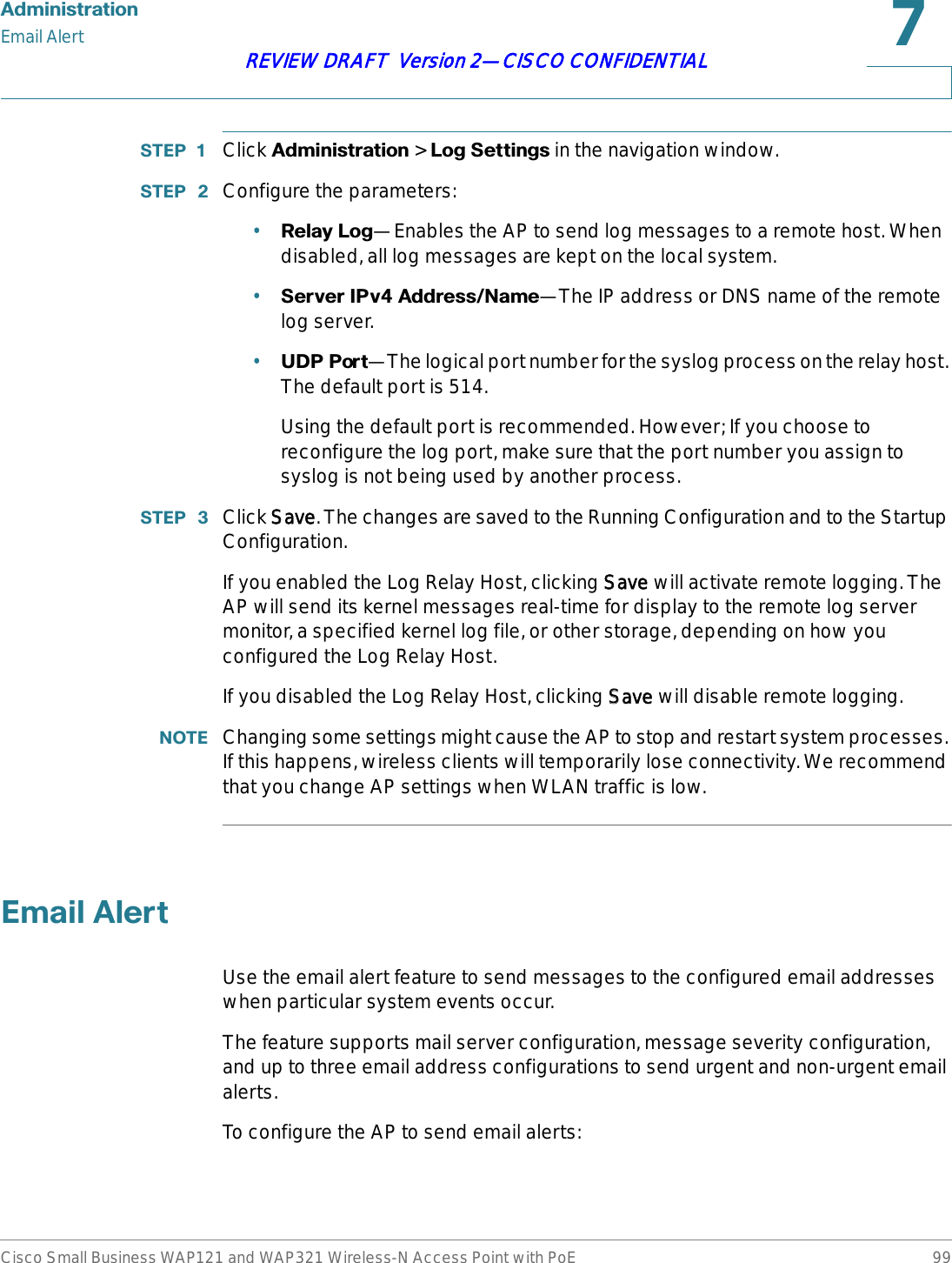
Sercomm Corporation Wireless-N Access Point with Power over Ethernet
Sercomm >
Contents
- 1. User manual 1 of 4
- 2. User manual 2 of 4
- 3. User manual 3 of 4
- 4. User manual 4 of 4
User manual 2 of 4
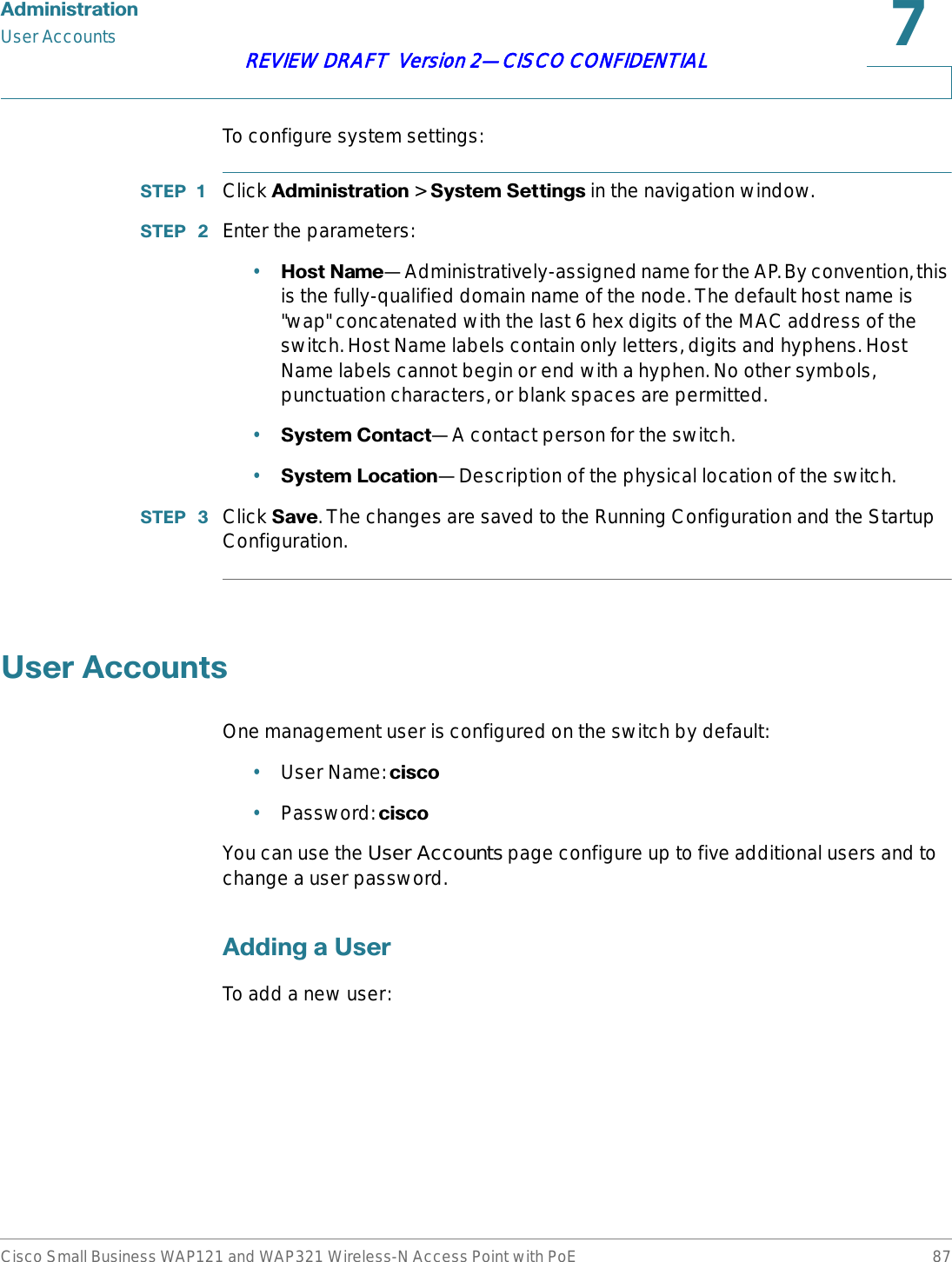
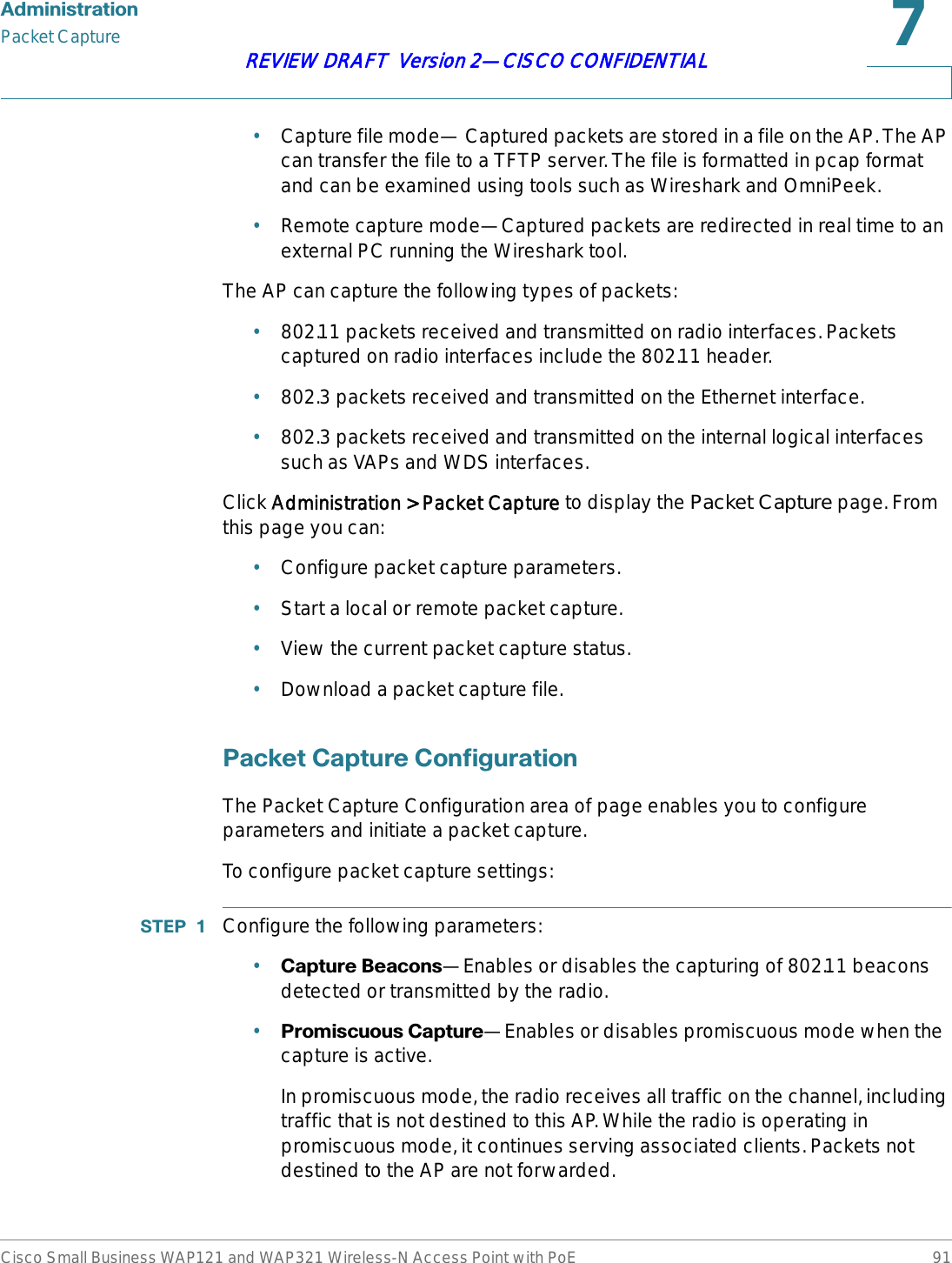
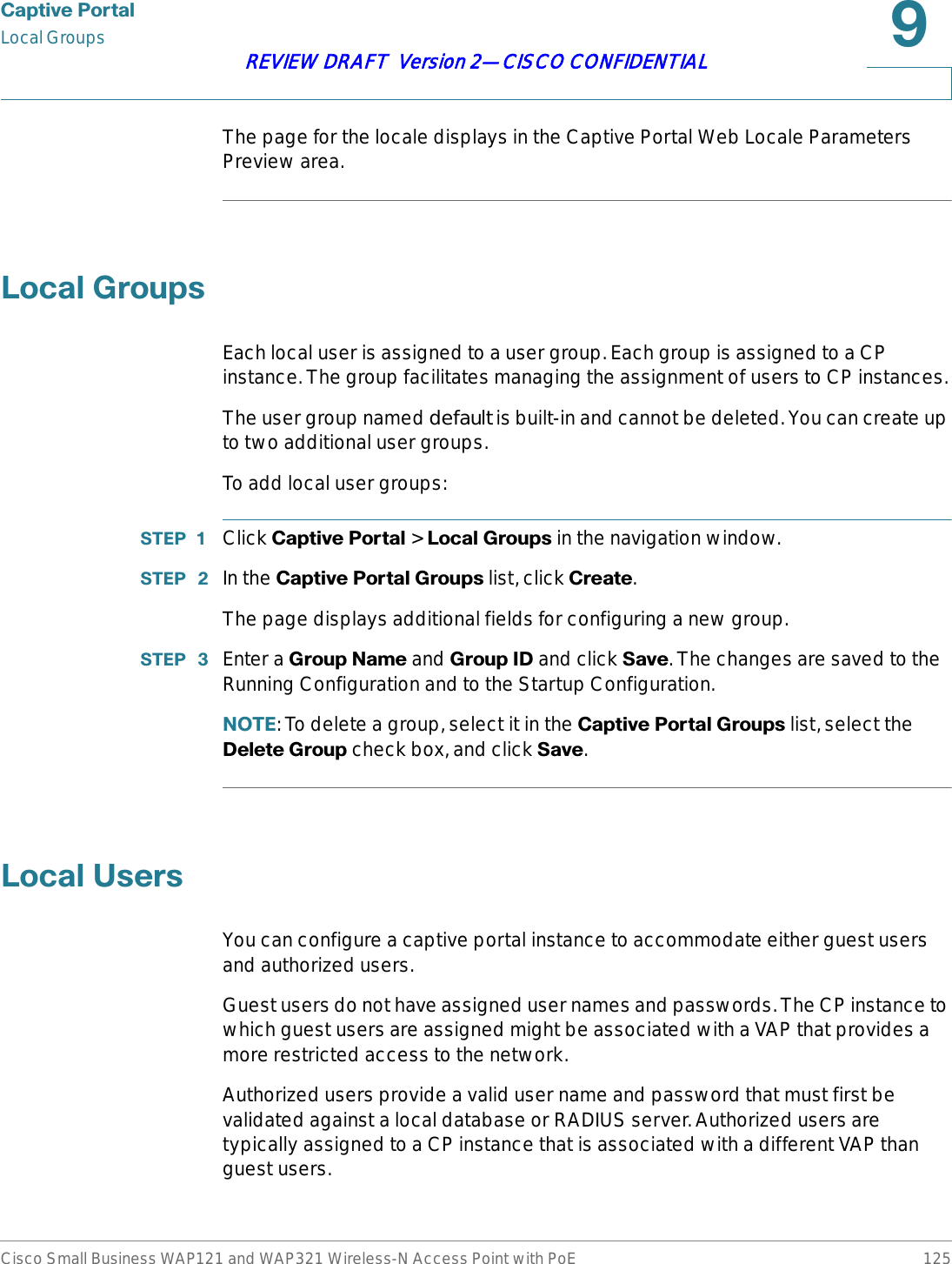
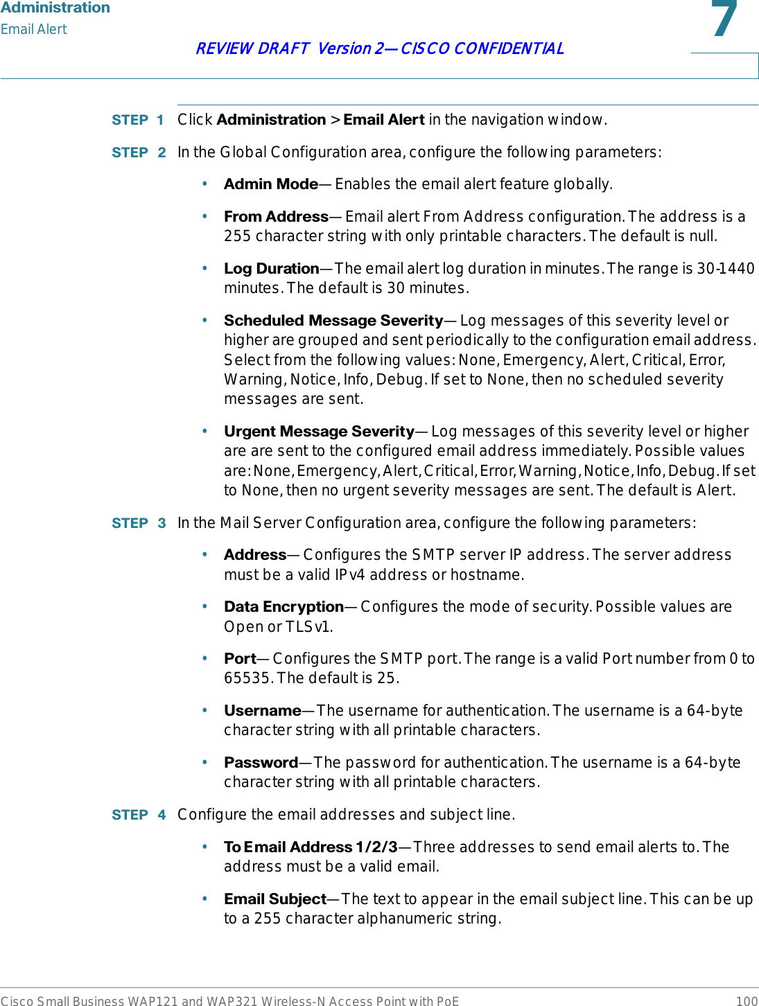
![$GPLQLVWUDWLRQPacket CaptureCisco Small Business WAP121 and WAP321 Wireless-N Access Point with PoE 93REVIEW DRAFT Version 2—CISCO CONFIDENTIAL-brtrunk—Linux bridge interface in the AP.•&DSWXUH'XUDWLRQ—The time duration in seconds for the capture (range 10 to 3600).•0D[&DSWXUH)LOH6L]H—The maximum allowed size for the capture file in KB (range 64 to 4096).67(3 Click 6DYH. The changes are saved to the Running Configuration and the Startup Configuration.67(3 Click 6WDUW&DSWXUH.In Packet File Capture mode, the AP stores captured packets in the RAM file system. Upon activation, the packet capture proceeds until one of the following occurs:•The capture time reaches configured duration.•The capture file reaches its maximum size.•The administrator stops the capture.The Packet Capture Status area of the page shows the status of a packet capture, if one is active on the AP. The following fields display:•&XUUHQW&DSWXUH6WDWXV—Whether packet capture is running or stopped.•3DFNHW&DSWXUH7LPH—Elapsed capture time.•3DFNHW&DSWXUH)LOH6L]H—The current capture file size.Click RRefresh to display the latest data from the AP.127( To stop a packet file capture, click 6WRS&DSWXUH.5HPRWH3DFNHW&DSWXUHThe Remote Packet Capture feature enables you to specify a remote port as the destination for packet captures. This feature works in conjunction with the Wireshark network analyzer tool for Windows. A packet capture server runs on the AP and sends the captured packets via a TCP connection to the Wireshark tool.A Windows PC running the Wireshark tool allows you to display, log, and analyze captured traffic.](https://usermanual.wiki/Sercomm/WAP121.User-manual-2-of-4/User-Guide-1592040-Page-23.png)
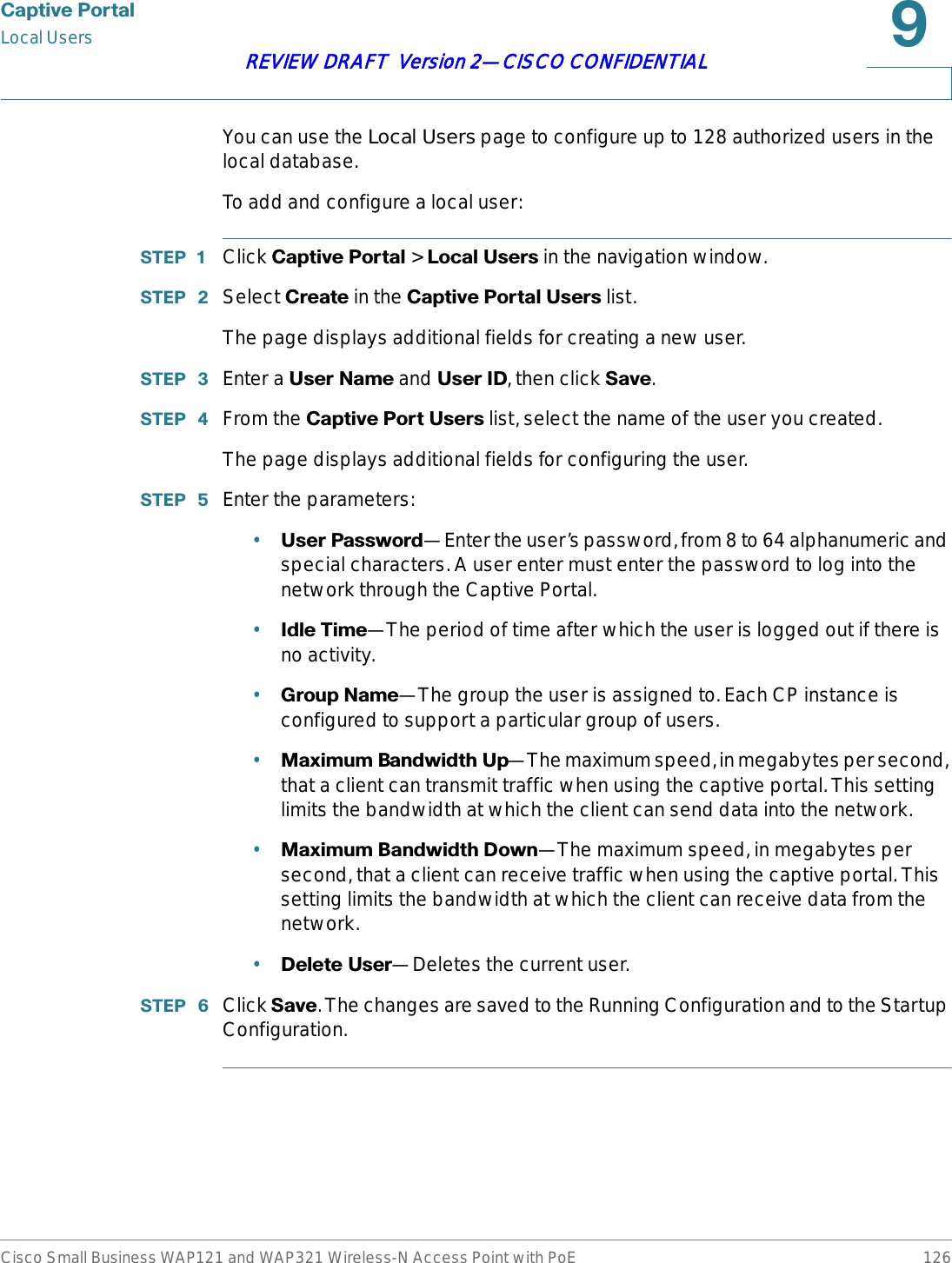
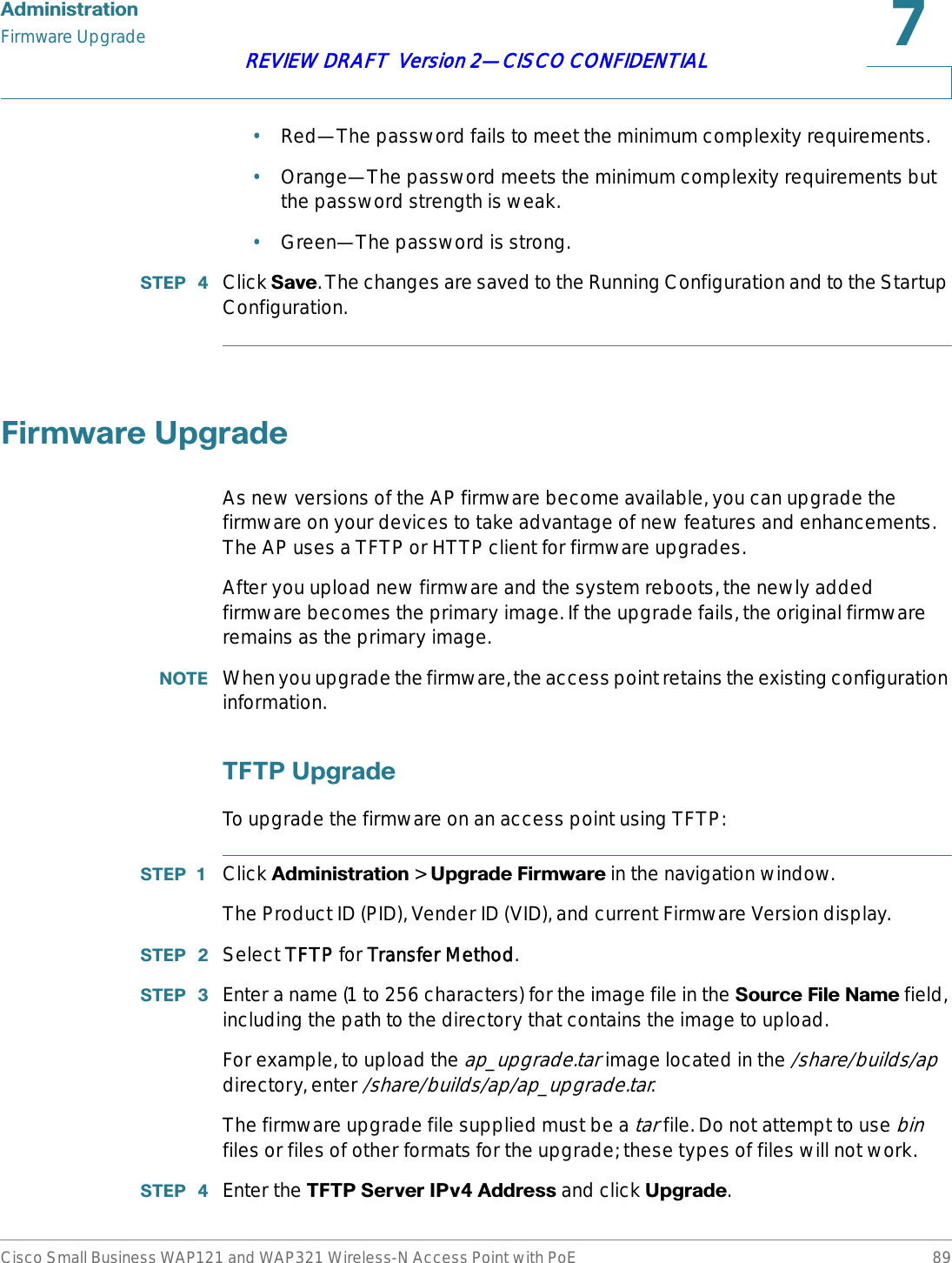
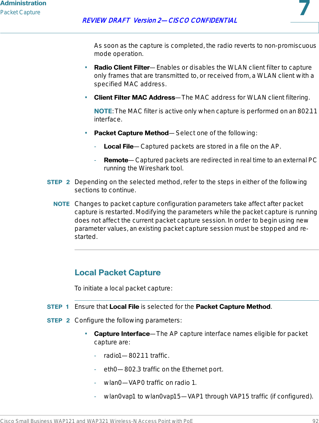
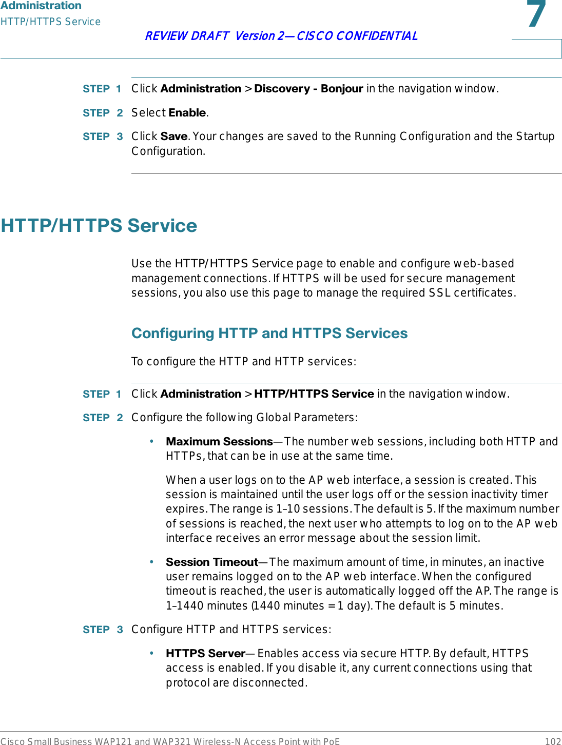
![$GPLQLVWUDWLRQDiscovery—BonjourCisco Small Business WAP121 and WAP321 Wireless-N Access Point with PoE 101REVIEW DRAFT Version 2—CISCO CONFIDENTIAL67(3 Click TTest Mail to validate the configured email server credentials. The administrator can send a test email once the email server details are configured.The following is a sample format of the email alert sent from the AP:From: AP-192.168.2.10@mailserver.com Sent: Wednesday, September 09, 2009 11:16 AMTo: administrator@mailserver.comSubject: log message from APTIME PriorityProcess Id MessageSep 8 03:48:25 info login[1457] root login on ‘ttyp0’Sep 8 03:48:26 info mini_http-ssl[1175] Max concurrent connections of 20 reached67(3 Click 6DYH. The changes are saved to the Running Configuration and to the Startup Configuration.'LVFRYHU\{%RQMRXUBonjour enables the AP and its services to be discovered by using multicast DNS (mDNS). Bonjour advertises services to the network and answers queries for service types it supports, simplifying network configuration in small business environments.The AP advertises the following service types:•&LVFRVSHFLILFGHYLFHGHVFULSWLRQ (csco-sb)—This service enables clients to discover Cisco AP and other products deployed in small business networks.•0DQDJHPHQWXVHULQWHUIDFHV—This service identifies the management interfaces available on the AP (HTTP, Telnet, SSH, and SNMP). When a Bonjour-enabled AP is attached to a network, any Bonjour client can discover and get access to the management interface without prior configuration.A system administrator can use an installed Internet Explorer plug-in to discover the AP. The web-based AP configuration utility shows up as a tab in the browser.Bonjour works in both IPv4 and IPv6 networks.To enable the AP to be discovered through Bonjour:](https://usermanual.wiki/Sercomm/WAP121.User-manual-2-of-4/User-Guide-1592040-Page-31.png)
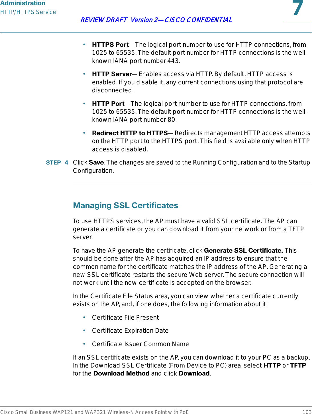
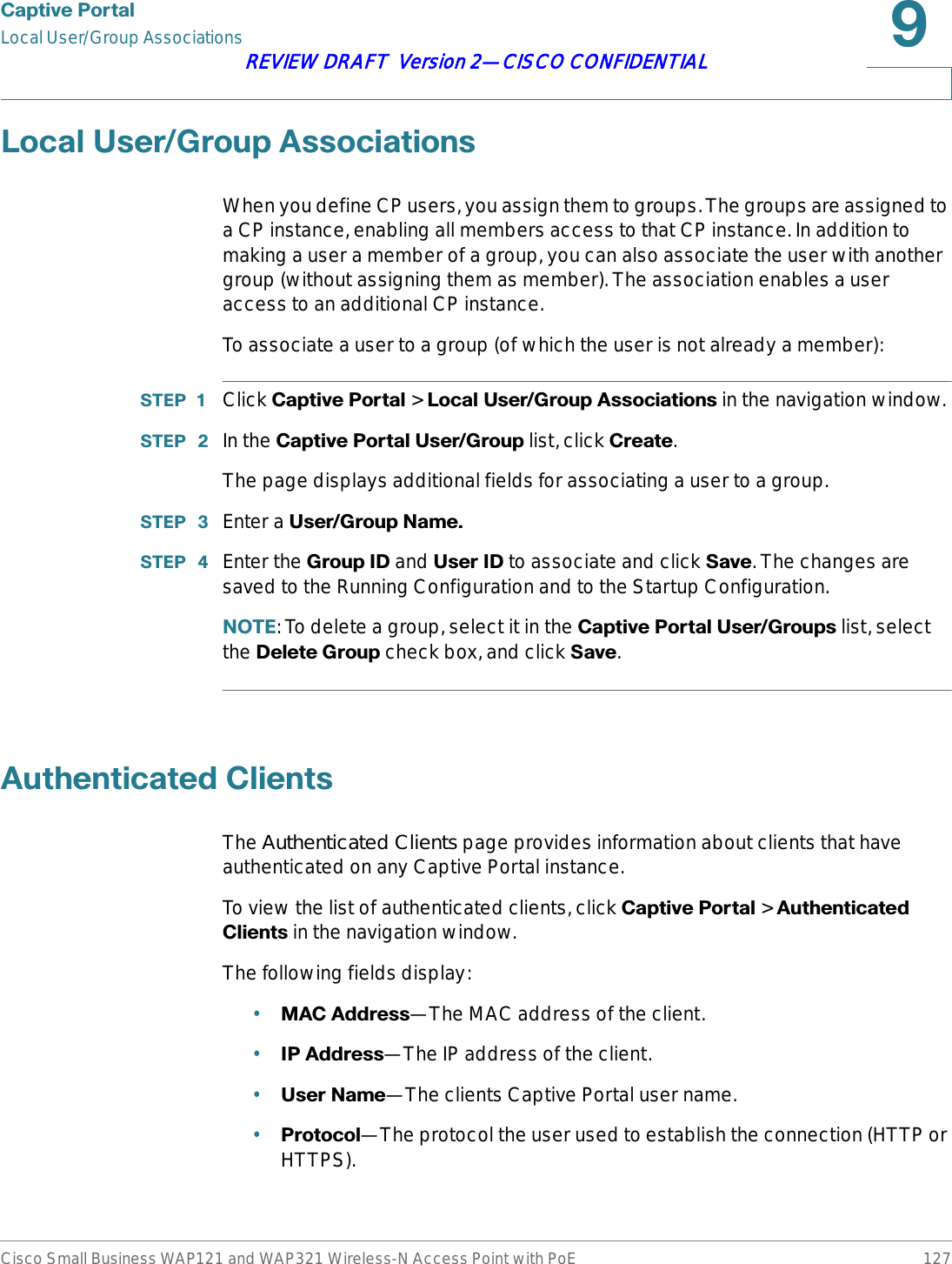
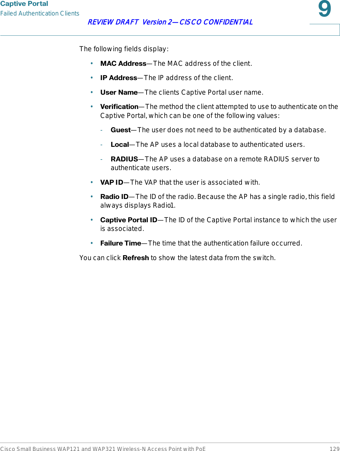
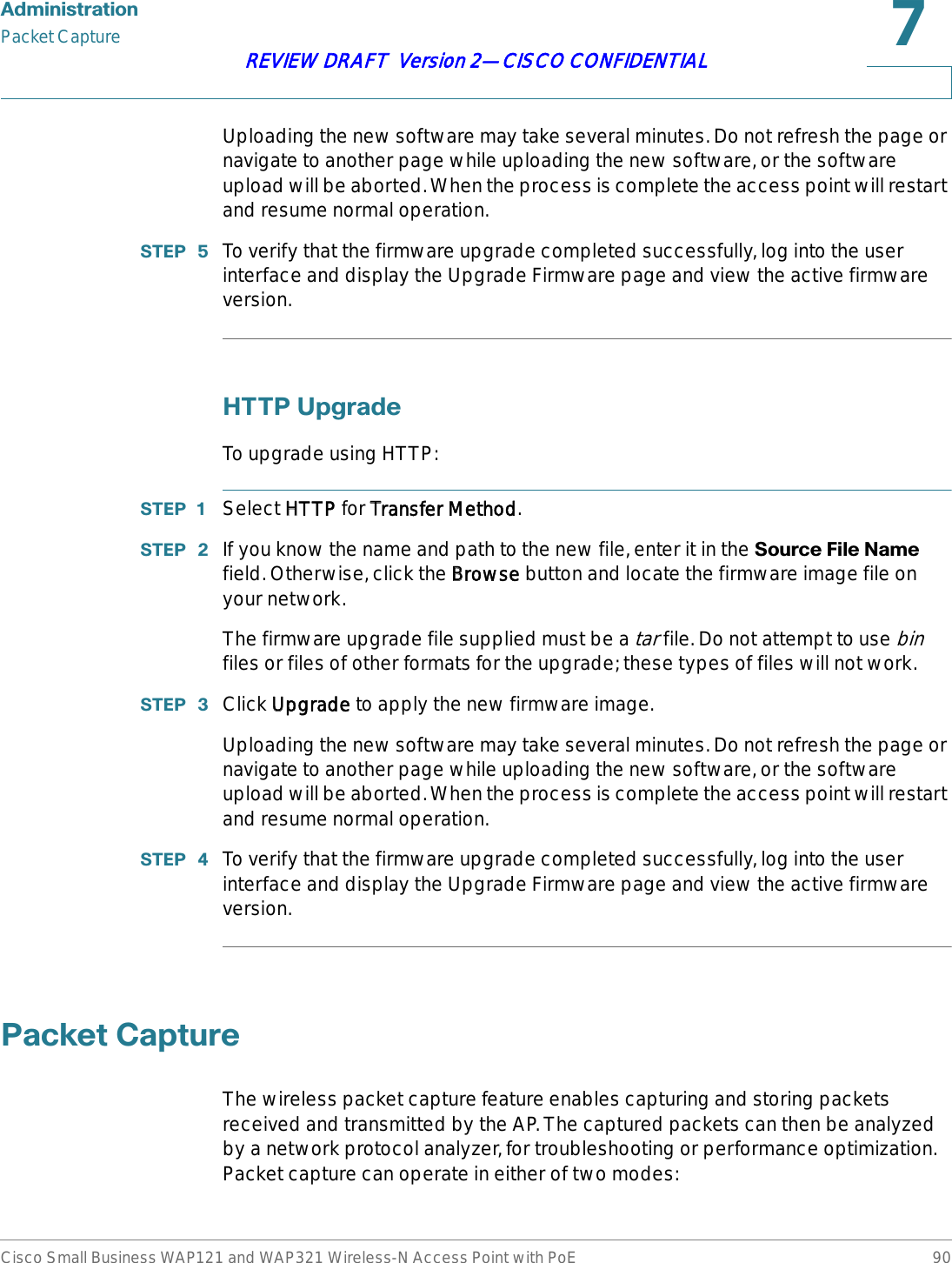
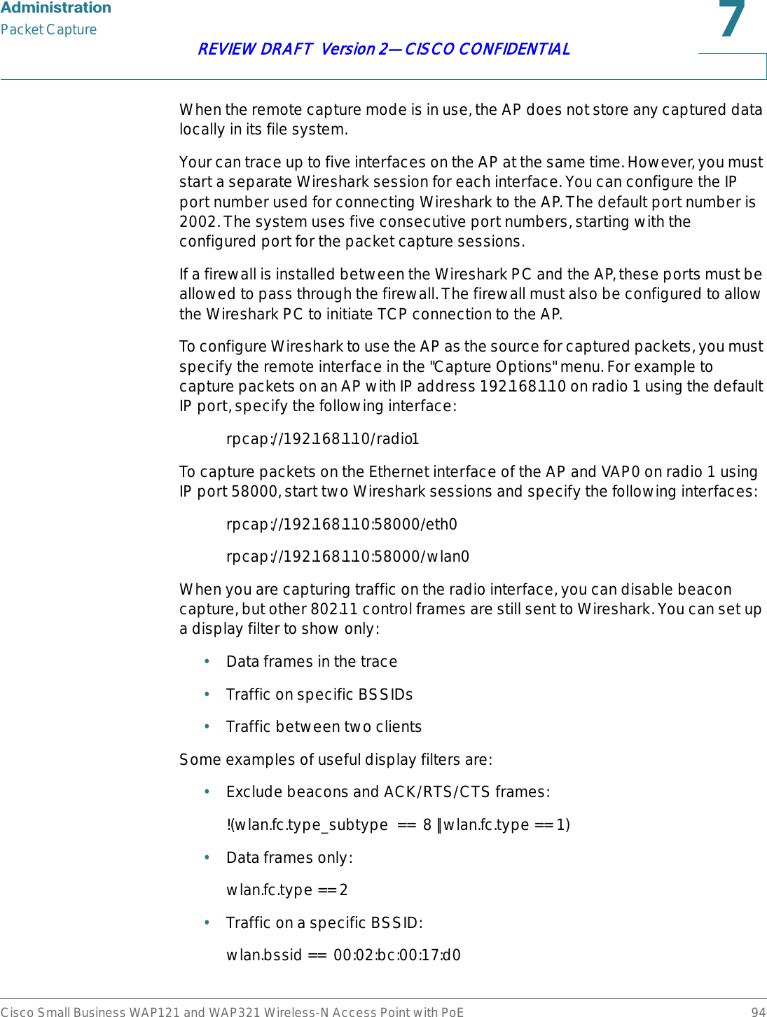
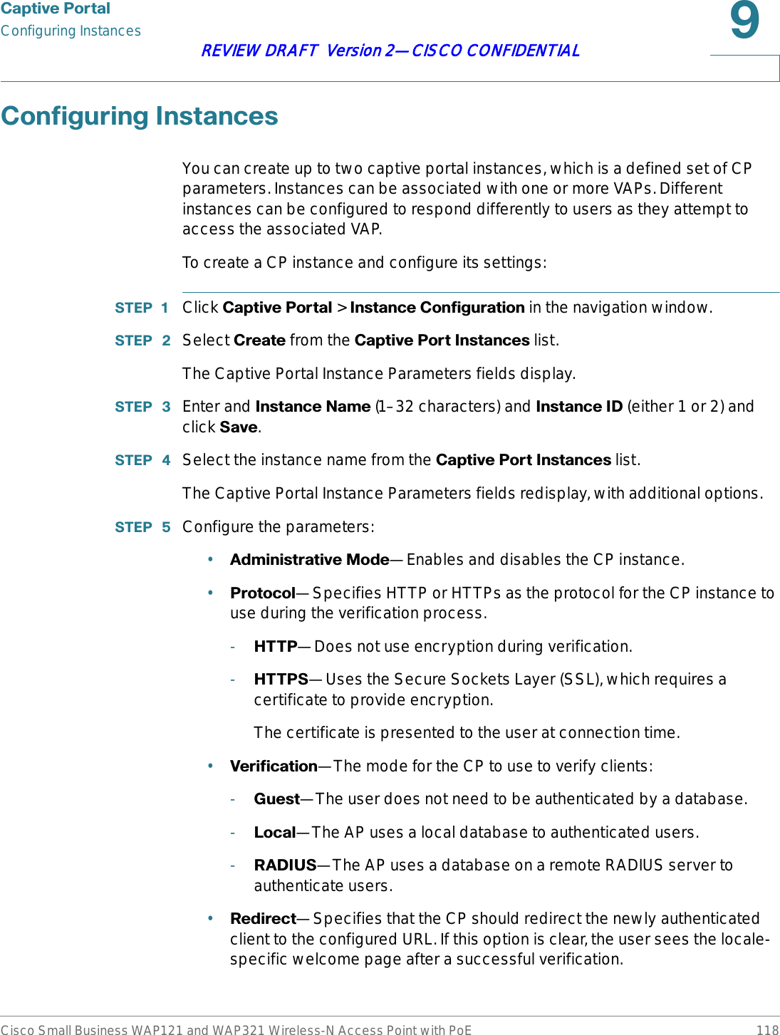
![9Cisco Small Business WAP121 and WAP321 Wireless-N Access Point with PoE 116REVIEW DRAFT Version 2—CISCO CONFIDENTIAL&DSWLYH3RUWDOThis chapter describes the Captive Portal feature, which allows you to block wireless clients from accessing the network until user verification has been established. You can configure CP verification to allow access for both guest and authenticated users.127( The Captive Portal feature is available only on the WAP321 AP.Authenticated users must be validated against a database of authorized Captive Portal users before access is granted. The database can be stored locally on the AP or on a RADIUS server.You can create up to two CP instances, which can then be assigned to VAPs in the system. The instances can be configured with different parameters that affect the user experience when attempting to access a particular VAP. For example, users may be redirected to a particular web page after authenticating to VAP0, but to another web page after authenticating to VAP1, based on the differing CP instances associated with each VAP.This chapter includes the following topics:•&RQILJXULQJ*OREDO&DSWLYH3RUWDO6HWWLQJV•&RQILJXULQJ,QVWDQFHV•&RQILJXULQJ9$3V•8SORDGLQJ%LQDU\)LOHV•&XVWRPL]LQJWKH&DSWLYH3RUWDO:HE3DJHV•:HE&XVWRPL]DWLRQ3UHYLHZ•/RFDO*URXSV•/RFDO8VHUV•/RFDO8VHU*URXS$VVRFLDWLRQV•$XWKHQWLFDWHG&OLHQWV](https://usermanual.wiki/Sercomm/WAP121.User-manual-2-of-4/User-Guide-1592040-Page-46.png)
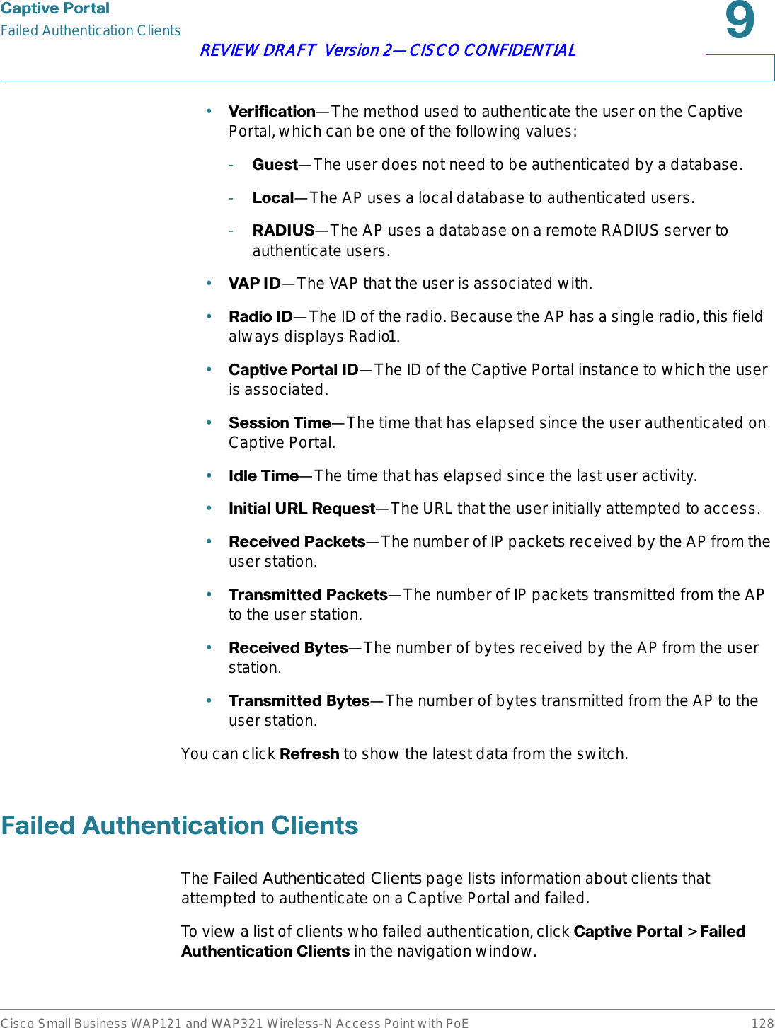
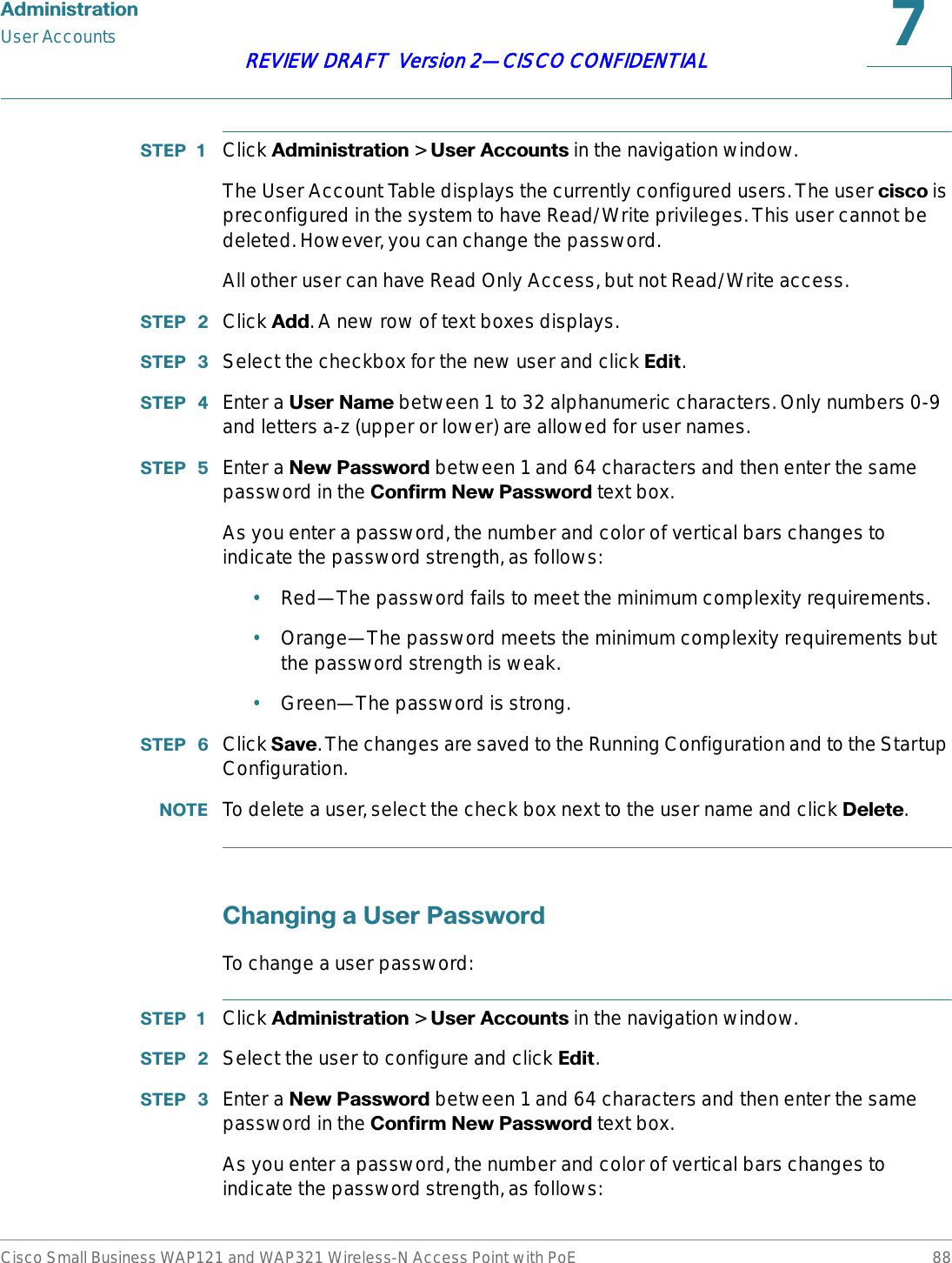
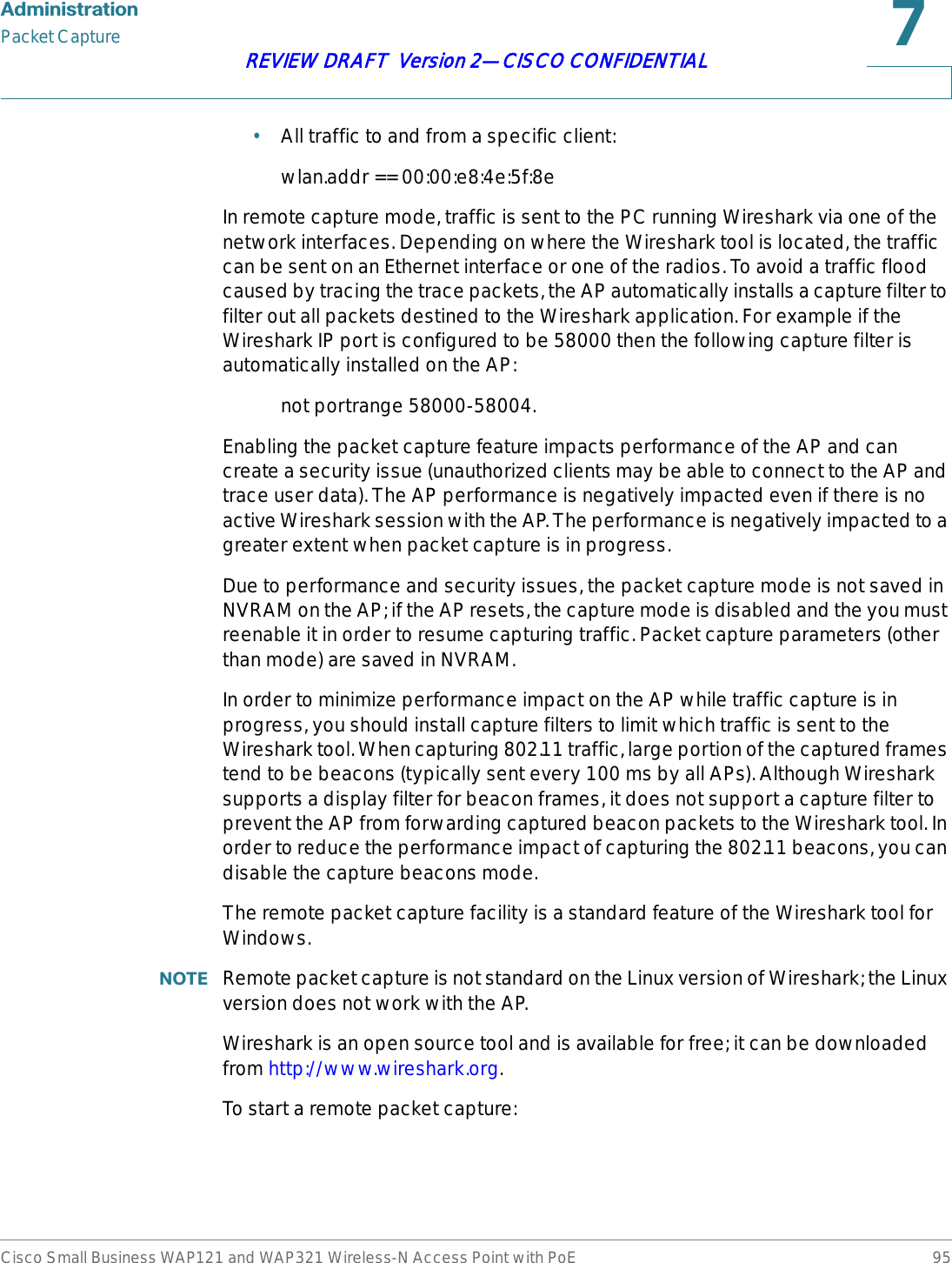
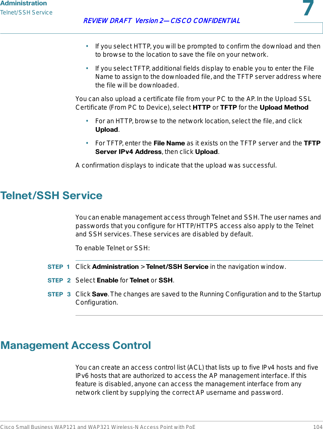
![&DSWLYH3RUWDOUploading Binary FilesCisco Small Business WAP121 and WAP321 Wireless-N Access Point with PoE 121REVIEW DRAFT Version 2—CISCO CONFIDENTIAL67(3 Click 6DYH. Your change are saved to the Running Configuration.8SORDGLQJ%LQDU\)LOHVWhen users initiate access to a VAP that is associated to a captive portal instance, an authentication page displays. You can customize this page with your own logo and other graphics. You can use the Upload Binary Files page to upload these graphics to the AP. To upload binary graphic files to the AP:67(3 Create or identify custom graphics to replace the default graphics, as shown in the following table.:Images will be resized to fit the specified dimensions. For best results, the logo and account images should be similar in proportion to the default images.All images must be 5 kilobytes or smaller and must be in GIF or JPG format.67(3 Click &DSWLYH3RUWDO > 8SORDG%LQDU\)LOHV in the navigation window.67(3 Click %URZVH next to 8SORDG:HE&XVWRPL]DWLRQ,PDJH to select the file from your PC or network.67(3 Click 8SORDG.67(3 Go to the Web Customization page to apply an uploaded graphic to a CP web page.,PDJH7\SH 8VH 'HIDXOW:LGWK[+HLJKWLogo Displays at top left of page to provide branding information. 168 × 78 pixelsAccount Displays above the login field to depict an authenticated login. 295 × 55 pixelsBackground Displays in the page background. 10 × 800](https://usermanual.wiki/Sercomm/WAP121.User-manual-2-of-4/User-Guide-1592040-Page-51.png)
![&DSWLYH3RUWDOCustomizing the Captive Portal Web PagesCisco Small Business WAP121 and WAP321 Wireless-N Access Point with PoE 122REVIEW DRAFT Version 2—CISCO CONFIDENTIAL127(: To delete an image, select it from the 'HOHWH:HE&XVWRPL]DWLRQ,PDJHlist and click 'HOHWH.&XVWRPL]LQJWKH&DSWLYH3RUWDO:HE3DJHVWhen users initiate access to a VAP that is associated to a captive portal instance, an authentication page displays. You can use the Web Customization page to create unique pages for different locales on your network, and to customize the textual and graphic elements of the pages.To create and customize a CP authentication page:67(3 Click &DSWLYH3RUWDO > :HE&XVWRPL]DWLRQ in the navigation window.67(3 Select &UHDWH from the &DSWLYH3RUWDO:HE/RFDOH list.You can create up to three pages for use with different locales on your network.67(3 Enter a :HE/RFDOH1DPH to assign to the page.67(3 Specify a /RFDOH,', from 1–3.67(3 From the &DSWLYH3RUWDO,QVWDQFHV list, select the CP instance that this locale is associated with.You can associate multiple locales with an instance. When a user attempts to access a particular VAP that is associated with a CP instance, the locales that are associated with that instance display as links on the authentication page. The user can select a link to switch to that locale.67(3 Click 6DYH. The changes are saved to the Running Configuration and to the Startup Configuration.67(3 From the &DSWLYH3RUWDO:HE/RFDOH list, select the locale you created.The page displays additional fields for modifying the locale. The /RFDOH,',,QVWDQFH,', and ,QVWDQFH1DPH fields display and cannot be edited. The editable fields are populated with default values.67(3 Configure the parameters:•%DFNJURXQG,PDJH1DPH—The image to display as the page background. If you uploaded a custom background image to the AP, you can select it from the list.](https://usermanual.wiki/Sercomm/WAP121.User-manual-2-of-4/User-Guide-1592040-Page-52.png)
![&DSWLYH3RUWDOWeb Customization PreviewCisco Small Business WAP121 and WAP321 Wireless-N Access Point with PoE 124REVIEW DRAFT Version 2—CISCO CONFIDENTIAL•$FFHSW/DEHO—The text that instructs users to select the check box to acknowledge reading and accepting the Acceptance Use Policy.•1R$FFHSW7H[W—Error: The text that displays in a pop-up window when a user submits login credentials without selecting the Acceptance Use Policy check box.•:RUN,Q3URJUHVV7H[W—The text that displays during authentication.•'HQLHG7H[W—The text that displays when a user fails authentication.•5HVRXUFH7H[W—The text that displays when the authenticator is unavailable.•7LPHRXW7H[W—The text that displays when the authenticator has not replied in the configured time frame. •:HOFRPH7LWOH—The text that displays when the client has authenticated to the VAP.•:HOFRPH&RQWHQW—The text that displays when the client has connected to the network.•'HOHWH/RFDOH—Deletes the current locale.67(3 Click 6DYH. Your changes are saved to the Running Configuration and the Startup Configuration.You can use the Web Customization Preview page view the updated page.:HE&XVWRPL]DWLRQ3UHYLHZUse the Web Customization Preview page to view a locale page that you have modified.To preview a customized page:67(3 Click &DSWLYH3RUWDO > :HE&XVWRPL]DWLRQ3UHYLHZ in the navigation window.67(3 Select the locale you want to preview from the &DSWLYH3RUWDO:HE/RFDOH list.](https://usermanual.wiki/Sercomm/WAP121.User-manual-2-of-4/User-Guide-1592040-Page-54.png)