Shin Heung Precision SAP-630 POS SYSTEM User Manual
Shin Heung Precision Co., Ltd. POS SYSTEM
UserManual.wiki
>
Shin Heung Precision
>
SAP 630 User Manual
User Manual
Navigation menu
Upload a User Manual
Namespaces
Wiki Guide
HTML
PDF
Info
Views
User Manual
Discussion / Help
Navigation
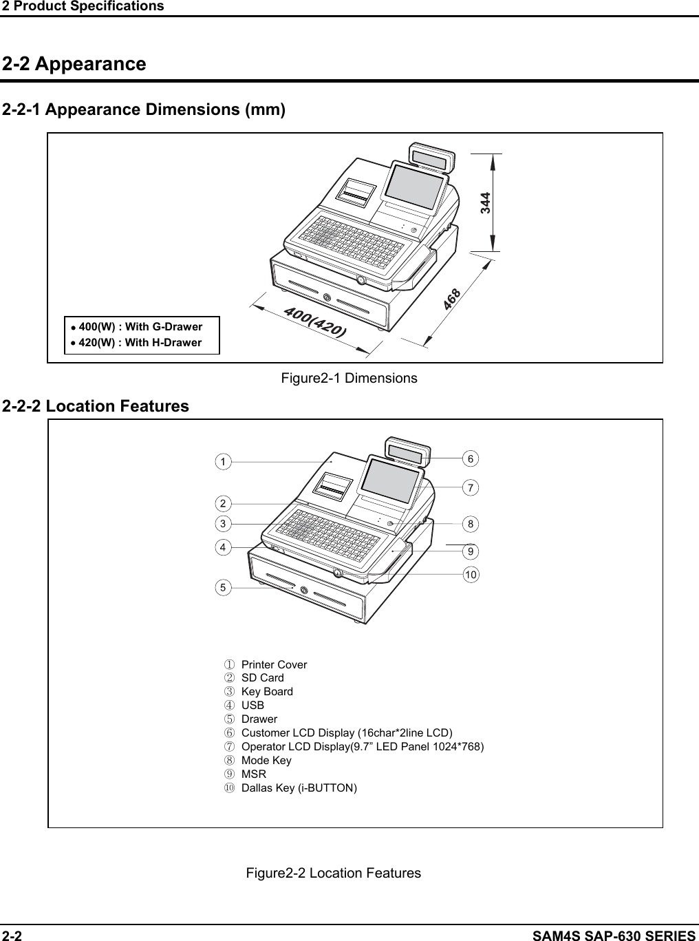
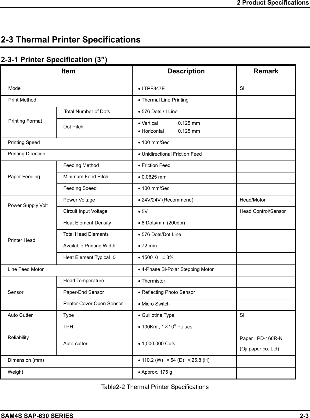
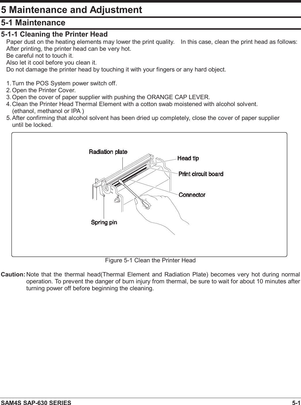
![SAM4S SAP-630 SERIES 2-1 2 Product Specifications Specifications are correct at the time of printing. Product specifications are subject to change without notice. See below for product specifications. General Specifications Item Description Remark PROCESSOR Intel Celeron N3160(Quad Core up to 2.24GHz) OS Android 6.0(Marshmallow) MEMORY Storage : eMMC 8GB SDRAM : DDR3 2GB SERIAL INTERFACE (RS-232C) Flow Control : ① CTS / RTS : H/W Flow Control ② XON / XOFF : S/W Flow Control Voltage Supply : VCC(+5V/1A) supplies at RS-232C#1~#4 RS-232C #1(DSUB-9) RS-232C #2(DSUB-9) RS-232C #3(RJ45) RS-232C #4(RJ45) LAN 10/100 base-T ETHERNET(TCP/IP) SD CARD 1-Slot [64GB_max] SDHC Compatible MSR 1-Slot [option] 1/2 Track or 2/3 Track i-BUTTON Magnetic [option] DRAWER 3-port [ Default (internal) #1 / RJ-11 #2,#3] USB 2-port [HOST] WIRELESS WiFi / Bluetooth [option] PRINTER Model : LTPF347E(SII) Printing Speed : 100mm/sec Detail Spec refer to Next Page AUTO CUTTER Type : Guillotine Cutting Method : 1 Point Partial Cutting DISPLAY Operator Display : 9.7” TFT-LCD(LED B/L), 1024x768 Customer Display : 16char*2line LCD TOUCH 5-Wire Resistive KEY BOARD Flat Rubber Key : 160 Key Raised Key : 90Key POWER CONSUMPTION Approx. 40W (Regularity) POWER REQUIREMENT AC 100-240V 50/60Hz ENVIRONMENT CONDITION Temperature : 0℃ ~ 45℃ humidity : 30% ~ 80% RH WEIGHT Approximately 12Kg DIMENSION(mm) 400(W) × 468(L) × 344(H) : With G-Drawer Set Size Table2-1 General Specifications](https://usermanual.wiki/Shin-Heung-Precision/SAP-630/User-Guide-3998213-Page-8.png)
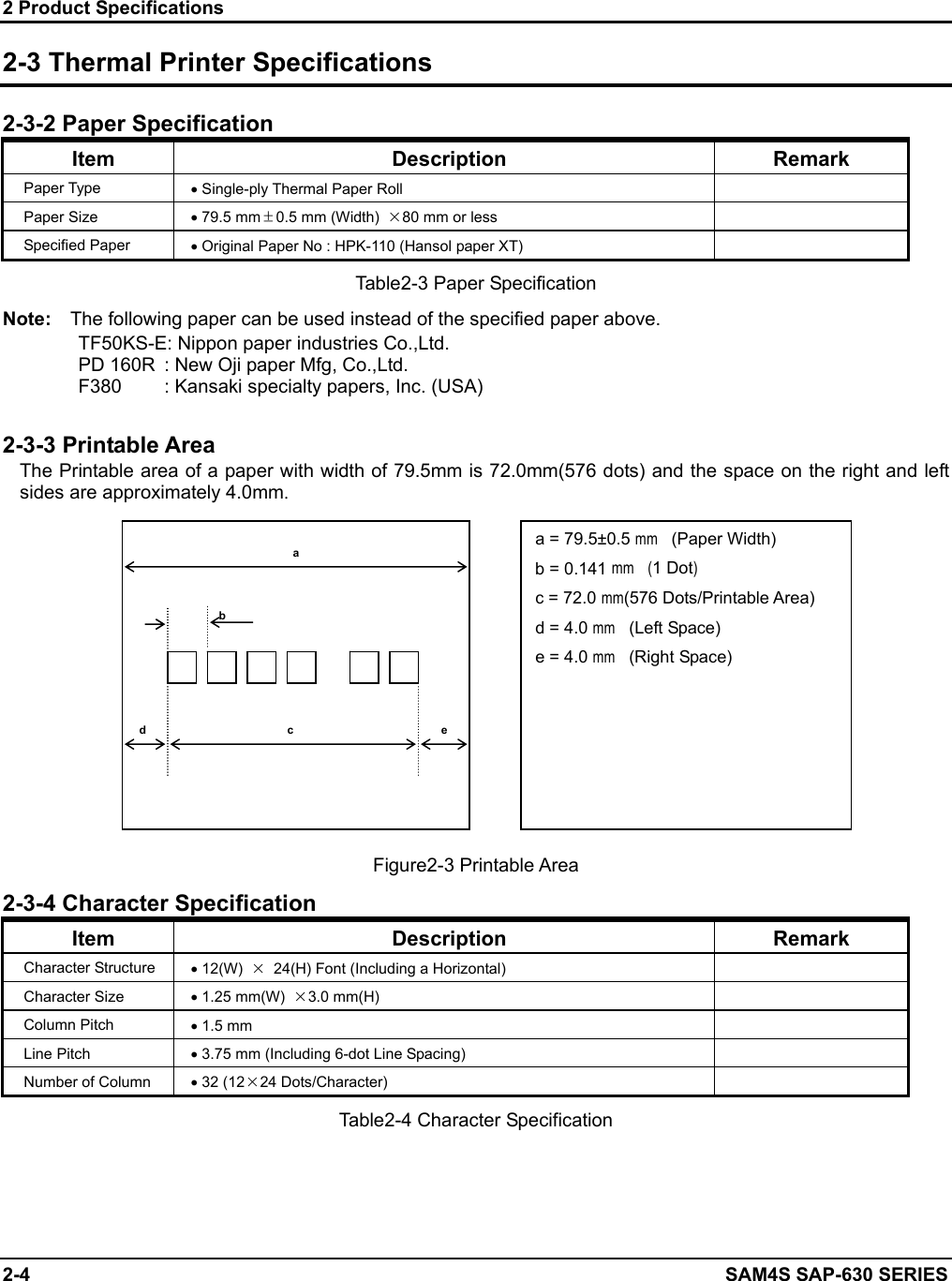
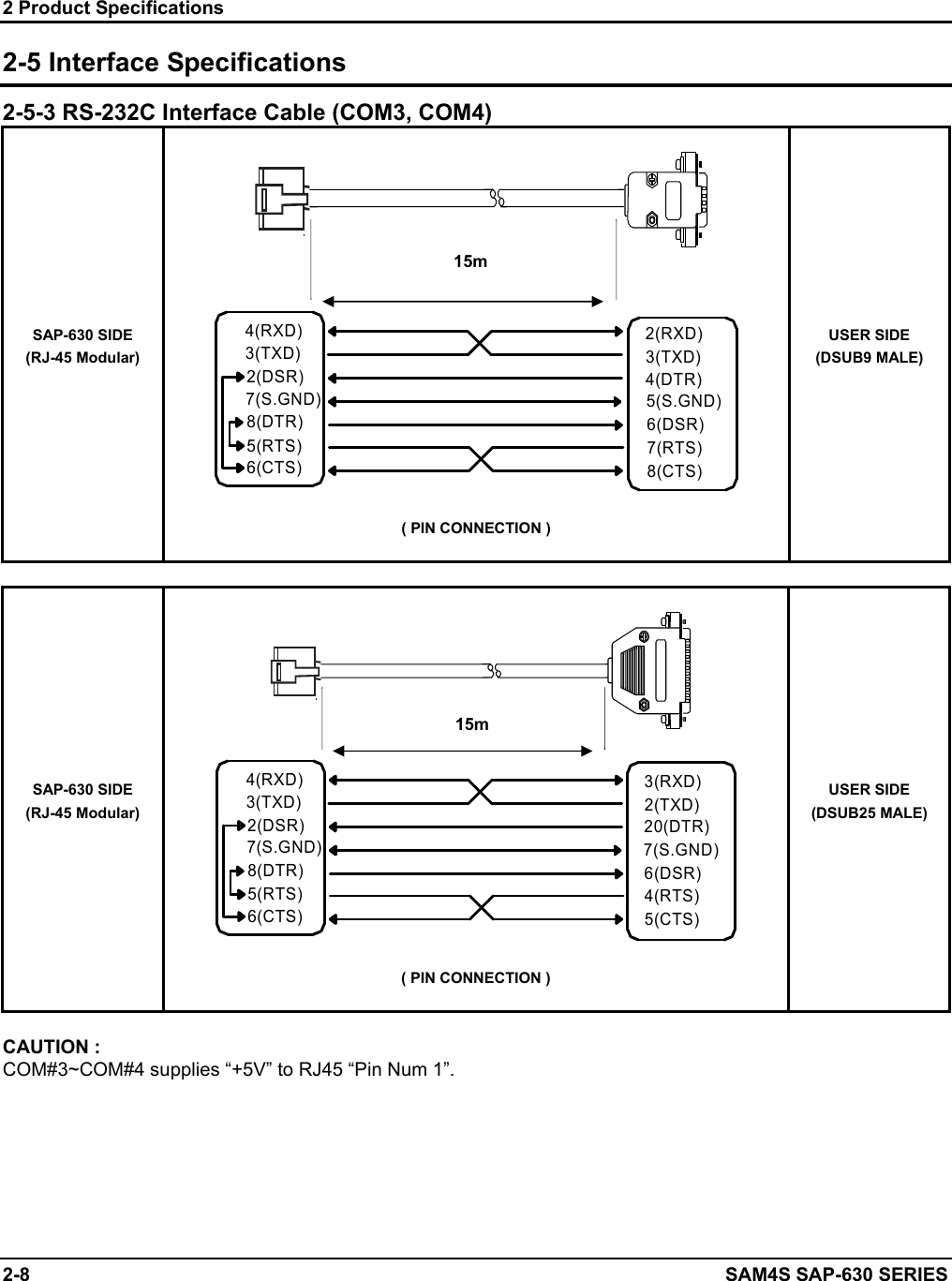
![2 Product Specifications SAM4S SAP-630 SERIES 2-5 2-4 Power Specifications 2-4-1 Power Specification Item Description Remark Input Voltage & Current AC 100~240V, 800mA, 50/60Hz (Min : 90V, Max : 264V) [AC/DC Adaptor(24V/2.5A) Internal] Power Consumption Peak : 50W Table2-5 Power Specification 2-5 Interface Specifications 2-5-1 RS-232C Serial Interface Specification Item Description Remark Data Transmission Serial Data Transmission Synchronization Asynchronous Hand Shaking (Flow Control) H/W : CTS / RTS S/W : XON / XOFF XON : ASC Code 11h XOFF : ASC Code 13h Signal Level Logic”1” (MARK) : -3V ~ -15V Logic”0” (SPACE) : +3V ~ +15V Baud Rate 2400 / 9600 / 19200 / 38400 / 57600 / 115200 bps Data Word Length 7 Bit / 8 Bit Parity None / Even / Odd Connector DB9P Male : COM#1, COM#2 RJ-45 Modular Jack : COM#3, COM#4 Voltage Supply VCC(+5V/1A):COM#1~#4 VCC(+5V/1A):USB#1~#2 Table2-6 RS-232C Serial Interface Specification CAUTION : “VCC” is supplied for the Barcode or other devices. Supply current 1A is total value including COM#1~COM#4. If the Total Power Consumption exceeds specification (1A), the system cuts “VCC” of COM#1~COM#4. “VCC “ is supplied for the USB Device. Supply current 1A is total value including USB1#~USB#2. If the total Power Consumption exceeds specification (1A), the system cuts “VCC” of USB#1~USB#2.](https://usermanual.wiki/Shin-Heung-Precision/SAP-630/User-Guide-3998213-Page-12.png)
![2 Product Specifications SAM4S SAP-630 SERIES 2-9 2-5 Interface Specifications 2-5-4 USB Interface Specification Item Description Remark Transfer Type ● BULK Data Signal ● Bi-Direction, Half-Duplex ● Differential Signal Pair (D+ / D-) Data Format ● NRZI Format ● Zero Bit Stuffing after 6 Ones Transceiver ● Differential Common Mode Range : 0.8 ~ 2.5[V] ● Differential Receive Sensitivity : 200[mV] ● Single End Receive Threshold : 0.8 ~ 2.5[V] Speed ● 480Mbps, 12Mbps Power ● Supply 5V/500mA (For HID) Cable & Connector ● Cable :5m/2m ● Connector :A type Support Spec ● USB Spec Version 2.0 2-5-5 USB Signal Description Pin No Signal Name Color Function SHELL Shield Drain Wire Frame GND 1 VBUS Red Host Power : DC5[V] / 500[mA] 2 D- White Differential Data Line 3 D+ Green Differential Data Line 4 GND Black Signal GND 2-5-6 USB Interface Cable SAP-630 SIDE "A" TYPE PLUG "B" TYPE PLUG ( USB CABLE ) USER SIDE](https://usermanual.wiki/Shin-Heung-Precision/SAP-630/User-Guide-3998213-Page-16.png)
![2 Product Specifications SAM4S SAP-630 SERIES 2-11 2-5 Interface Specifications 2-5-9 DRAWER Signal Description Pin No Signal Name Direction Function 1 S.G - Signal GND 2 DRAWER#OUT OUT Drawer Kick-Out Driver Signal. 3 DRA_COMP IN Drawer Open / Close Signal 4 +24V - Supply DC +24[V] 5 DRAWER#OUT OUT Drawer Kick-Out Driver Signal. 6 F.G - Frame GND CAUTION : Make sure that installed “+24V Cash Drawer”. Make sure that the Cash Drawer Solenoid Resistance is more than 20[Ohm] 2-5-10 DRAWER Interface Cable SAP-630 SIDE RJ11 6P COMPULSORYDRAWER (DRAWER I/F CABLE) 61 ( DRAWER CONNECTOR ) USER SIDE](https://usermanual.wiki/Shin-Heung-Precision/SAP-630/User-Guide-3998213-Page-18.png)
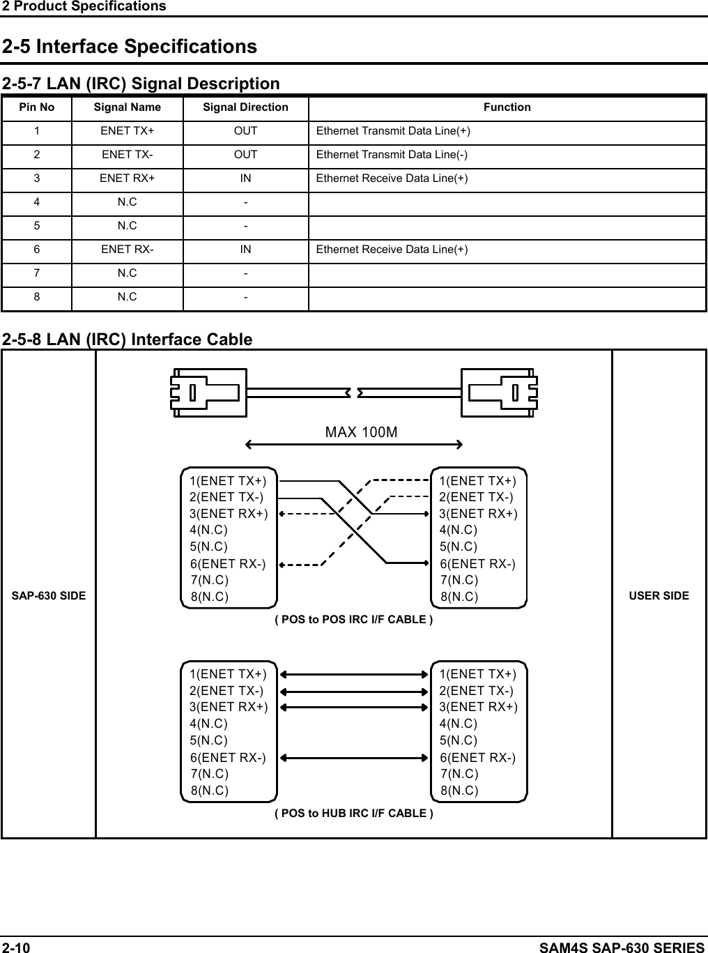
![6 Troubleshooting 6-4 SAM4S SAP-630 SERIES 6-4 LAN, USB, Serial Port Problem 6-4-1 LAN Cable NOT attached (Green LED of LAN connector does not turn on). → Check LAN cable. Refer to chapter 2 cable connection diagram. → For IRC (Inter Register Communication), It has to be used the cross cable. → For LAN, It has to be used the direct connection cable. → Check LAN RJ-45 modular jack insert right position.. Communication fail occurs (Yellow LED of LAN connector does not blank). → Check LAN cable whether cable wire is open or not. → Check cable length. Based on LAN specification, the cable length has to less than 100M. → Check MAIN B’D and related circuit & component whether short or not. Related System Clock. → Check the crystal, if it operates correctly or not. → Clock frequency is 25MHz. (LX1) 6-4-2 USB USB device NOT attached and Communication fail occurs. → Check USB device whether it is broken or not. → Check USB version. This product supports USB 2.0 version. → Check related circuit & component whether short or not. → Check USB source voltage (+5V) for HID (Ex ; Mouse, Keyboard, Scanner…etc,.) → Check the Cable for front USB Connector 6-4-3 Serial (COM#1 ~ COM#4) Communication fail occurs. → Check communication setting parameter (Speed, Parity, Data Bit…etc,.) → Check the interface cable. Refer to Chapter 2 for cable connection. → Check the RS232 driving voltage (+12V, -12V). → Measure +12V, -12V on main B’D. If -12V voltage level is less than -7.0V, it is OK. → Check related circuit & component whether open or not. → Check controller chip and related circuit. (COM#1:U43, COM#2:U44, COM#3:U46, COM#4:U45) → Perform the loop-back test at self test mode. Refer to Chapter3 for loop-back connection. Scanner device NOT attached and Communication fail occurs. → The source voltage (+5V) for scanner comes out at COM#1,#2,#3,#4.. → Check the power consumption of scanner. This product limits the power current; → Scanner is less than 300[mA]. (Recommend) → Check related circuit & component whether open or not. 6-4-4 SDCARD Operation Fail. → Performs the SDCARD test at H/W test Utility. → Check the harness between SD B’D and Main B’D, if it is connected or not. → Check the 10-Pin harness, it is OK or not. → Check related circuit & component whether short or not.](https://usermanual.wiki/Shin-Heung-Precision/SAP-630/User-Guide-3998213-Page-60.png)