Shin Heung Precision SAP-630 POS SYSTEM User Manual
Shin Heung Precision Co., Ltd. POS SYSTEM
User Manual
SAP-630 Series C O N T E N T S
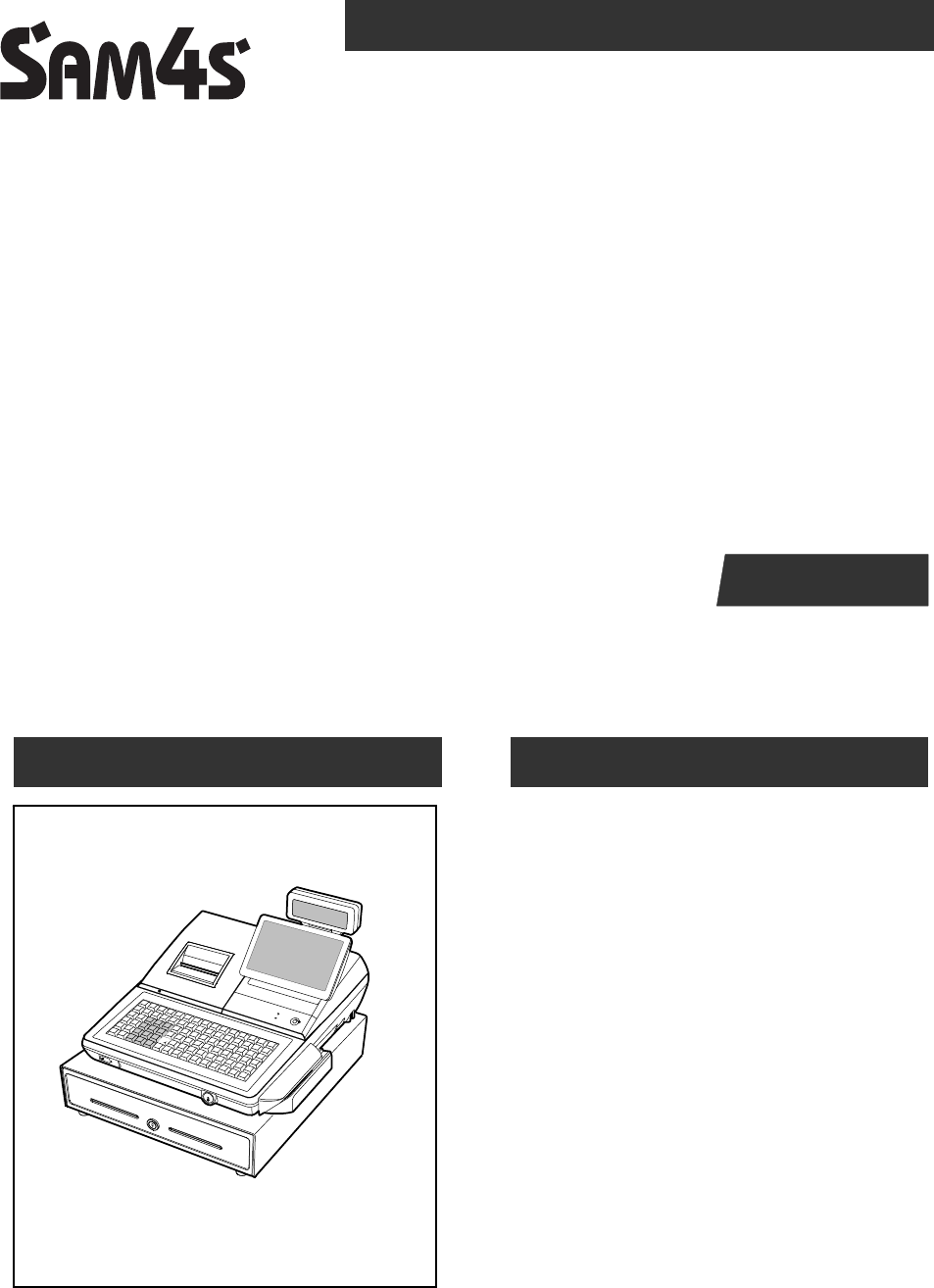
SAP-630 SERIES
POS SYSTEM
Manual
1. Precaution Statements
2. Product Specifications
3. Installation and Operation
4. Disassembly and Assembly
5. Maintenance and Adjustment
6. Troubleshooting
7. Exploded Views and Parts List
8. PCB Layout and Parts List
9. Wiring Diagram
10. Bock Diagram
11. Schematic Diagrams
SERVICE

About this Manual
This service manual describes how to
perform hardware service maintenance for
the SAM4S SAP-630 Series POS System
Notes
Notes may appear anywhere in the manual.
They describe additional information about
the item.
Precaution symbols
. Indicates a Safety Precaution that
applies to this part component.
. Indicates the part or component is an
electro-statically sensitive device. Use
caution when handling these parts.

Copyright
20ⓒ18 by Shin Heung Precision.
All right reserved.
This manual may not, in whole or in part, be
copied, photocopied, reproduced, translated
or converted to any electronic or machine
readable from without prior written
permission of Shin Heung Precision .
SAM4S SAP-630 SERIES
July. 2018
V1.0
Printed in KOREA

Overview of this POS System
This service manual provides the technical information for many individual component systems and circuits and
gives an analysis of the operations performed by the circuits. Schematics and specifications provide the needed
information for the accurate troubleshooting.
All information in this manual is subject to change without prior notice. Therefore, you must check the
correspondence of your manual with your machine. No part of this manual may be copied or reproduced in any
form or by any means, without the prior written consent of Shin Heung Precision.

SAM4S SAP-630 SERIES 1-1
1 Precaution Statements
Follow these safety, servicing and ESD precautions to prevent damage and to protect against potential hazards
such as electrical shock.
1-1 Safety Precautions
1. Be sure that all built-in protective devices are
replaced. Restore any missing protective
shields.
2. When reinstalling the chassis and its
assemblies, be sure to restore all protective
devices, including nonmetallic control knobs and
compartment covers.
3. Make sure there are no cabinet openings
through which people - particularly children -
might insert fingers and contact dangerous
voltages. Such openings include excessively
wide cabinet ventilation slots and improperly
fitted covers and drawers.
4. Design Alteration Warning:
Never alter or add to the mechanical or
electrical design of the POS. Unauthorized
alterations might create a safety hazard. Also,
any design changes or additions will void the
manufacturer’s warranty.
5. Components, parts and wiring that appear to
have overheated or that are otherwise damaged
should be replaced with parts that meet the
original specifications. Always determine the
cause of damage or over- heating, and correct
any potential hazards.
6. Observe the original lead dress, especially near
the following areas : sharp edges, and
especially the AC and high voltage supplies.
Always inspect for pinched, out-of-place, or
frayed wiring. Do not change the spacing
between components and the printed circuit
board. Check the AC power cord for damage.
Make sure that leads and components do not
touch thermally hot parts.
7. Product Safety Notice:
Some electrical and mechanical parts have
special safety-related characteristics which
might not be obvious from visual inspection.
These safety features and the protection they
give might be lost if the replacement component
differs from the original - even if the
replacement is rated for higher voltage, wattage,
etc.
Components that are critical for safety are
indicated in the circuit diagram by shading,
() or ( ). Use replacement components
that have the same ratings, especially for
flame resistance and dielectric strength
specifications. A replacement part that does
not have the same safety characteristics as the
original might create shock, fire or other
hazards.
8. The socket-outlet shall be installed near
The equipment and shall be easily accessible
9. This device complies with part 15 of the FCC
Rules. Operation is subject to the following two
conditions:
(1) This device may not cause harmful interference,
and
(2) This device must accept any interference
received, including interference that may cause
undesired operation
10. This equipment has been tested and found to
comply with the limits for a Class A digital device,
pursuant to part 15 of the FCC Rules. These limits
are designed to provide reasonable protection
against harmful interference when the equipment is
operated in a commercial environment. This
equipment generates, uses, and can radiate radio
frequency energy and, if not installed and used in
accordance with the instruction manual, may cause
harmful interference to radio communications.
Operation of this equipment in a residential area is
likely to cause harmful interference in which case
the user will be required to correct the interference
at his own expense

1 Precaution Statements
1-2 SAM4S SAP-630 SERIES
THE GRANTEE IS NOT RESPONSIBLE FOR ANY
CHANGES OR MODIFICATIONS NOT
EXPRESSLY APPROVED BY THE PARTY
RESPONSIBLE FOR COMPLIANCE. SUCH
MODIFICATIONS COULD VOID THE USER ’ S
AUTHORITY TO OPERATE THE EQUIPMENT
IMPORTANT NOTE : FCC RF Radiation Exposure
Statement
This equipment complies with FCC RF radiation
exposure limits set forth for an uncontrolled
environment. This equipment should be installed
and operated with a minimum distance of 20
centimeters between the radiator and your body.
This transmitter must not be co-located or operating
in conjunction with any other antenna or transmitter.
CAUTION
RISK OF EXPLOSION IF BATTERY IS REPLACED
BY AN INCORRECT TYPE.
DISPOSE OF USED BATTERIES ACCORDING
TO THE INSTRUCTIONS
ATTENTION
IL Y A RISQUE D'EXPLOSION SI LA BATTERIE EST
REMPLACÉE
PAR UNE BATTERIE DE TYPE INCORRECT.
METTRE AU REBUT LES BATTERIES USAGÉES
CONFORMÉMENT AUX INSTRUCTIONS

1 Precaution Statements
1-3 SAM4S SAP-630 SERIES
1-2 Servicing Precautions
WARNING: First read the-Safety Precautions-section of this manual. If some unforeseen circumstance creates
a conflict between the servicing and safety precautions, always follow the safety precautions.
WARNING: An electrolytic capacitor installed with the wrong polarity might explode.
1. Servicing precautions are printed on the cabinet.
Follow them.
2. Always unplug the units AC power cord from the
AC power source before attempting to:
(a) Remove or reinstall any component or
assembly (b) Disconnect an electrical plug or
connector (c) Connect a test component in
parallel with an electrolytic capacitor
3. Some components are raised above the printed
circuit board for safety. An insulation tube or
tape is sometimes used. The internal wiring is
sometimes clamped to prevent contact with
thermally hot components. Reinstall all such
elements to their original position.
4. After servicing, always check that the screws,
components and wiring have been correctly
reinstalled. Make sure that the portion around the
serviced part has not been damaged.
5. Check the insulation between the blades of the
AC plug and accessible conductive parts
(examples : metal panels and input terminals).
6. Insulation Checking Procedure:
Disconnect the power cord from the AC source
and turn the power switch ON. Connect an
insulation resistance meter (500V) to the blades
of AC plug.
The insulation resistance between each blade of
the AC plug and accessible conductive parts
(see above) should be greater than 1 megaohm.
7. Never defeat any of the B+ voltage interlocks.
Do not apply AC power to the unit (or any of its
assemblies) unless all solid-state heat sinks are
correctly installed.
8. Always connect an instrument’s ground lead to
the instrument chassis ground before connecting
the positive lead ; always remove the
instrument’s ground lead last.
1-3 Precautions for Electrostatically Sensitive Devices (ESDs)
1. Some semiconductor (solid state) devices are easily
damaged by static electricity. Such components are
called Electrostatically Sensitive Devices (ESDs);
examples include integrated circuits and some field-
effect transistors. The following techniques will reduce
the occurrence of component damage caused by static
electricity.
2. Immediately before handling any semiconductor
components or assemblies, drain the electrostatic
charge from your body by touching a known earth
ground. Alternatively, wear a discharging wrist-strap
device. (Be sure to remove it prior to applying power -
this is an electric shock precaution.)
3. After removing an ESD-equipped assembly, place it
on a conductive surface such as aluminum foil to
prevent accumulation of electrostatic charge.
4. Do not use freon-propelled chemicals. These can
generate electrical charges that damage ESDs.
5. Use only a grounded-tip soldering iron when soldering
or unsoldering ESDs.
6. Use only an anti-static solder removal device. Many
solder removal devices are not rated as anti-static;
these can accumulate sufficient electrical charge to
damage ESDs.
7. Do not remove a replacement ESD from its protective
package until you are ready to install it. Most
replacement ESDs are packaged with leads that are
electrically shorted together by conductive foam,
aluminum foil or other conductive materials.
8. Immediately before removing the protective material
from the leads of a replacement ESD, touch the
protective material to the chassis or circuit assembly
into which the device will be installed.
9. Minimize body motions when handling unpackaged
replacement ESDs. Motions such as brushing clothes
together, or lifting a foot from a carpeted floor can
generate enough static electricity to damage an ESD.
SAM4S SAP-630 SERIES 2-1
2 Product Specifications
Specifications are correct at the time of printing. Product specifications are subject to change without notice.
See below for product specifications.
General Specifications
Item Description Remark
PROCESSOR Intel Celeron N3160(Quad Core up to 2.24GHz)
OS Android 6.0(Marshmallow)
MEMORY
Storage : eMMC 8GB
SDRAM : DDR3 2GB
SERIAL
INTERFACE
(RS-232C)
Flow Control :
① CTS / RTS : H/W Flow Control
② XON / XOFF : S/W Flow Control
Voltage Supply : VCC(+5V/1A) supplies at RS-232C#1~#4
RS-232C #1(DSUB-9)
RS-232C #2(DSUB-9)
RS-232C #3(RJ45)
RS-232C #4(RJ45)
LAN
10/100 base-T
ETHERNET(TCP/IP)
SD CARD 1-Slot [64GB_max] SDHC Compatible
MSR 1-Slot [option] 1/2 Track or 2/3 Track
i-BUTTON Magnetic [option]
DRAWER 3-port [ Default (internal) #1 / RJ-11 #2,#3]
USB 2-port [HOST]
WIRELESS WiFi / Bluetooth [option]
PRINTER
Model : LTPF347E(SII)
Printing Speed : 100mm/sec
Detail Spec refer to Next
Page
AUTO CUTTER
Type : Guillotine
Cutting Method : 1 Point Partial Cutting
DISPLAY
Operator Display : 9.7” TFT-LCD(LED B/L), 1024x768
Customer Display : 16char*2line LCD
TOUCH 5-Wire Resistive
KEY BOARD
Flat Rubber Key : 160 Key
Raised Key : 90Key
POWER
CONSUMPTION
Approx. 40W (Regularity)
POWER
REQUIREMENT
AC 100-240V 50/60Hz
ENVIRONMENT
CONDITION
Temperature : 0℃ ~ 45℃
humidity : 30% ~ 80% RH
WEIGHT Approximately 12Kg
DIMENSION(mm) 400(W) × 468(L) × 344(H) : With G-Drawer Set Size
Table2-1 General Specifications
2 Product Specifications
2-2 SAM4S SAP-630 SERIES
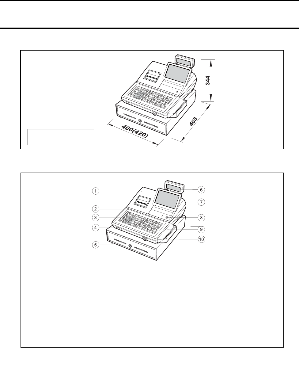
2-2 Appearance
2-2-1 Appearance Dimensions (mm)
Figure2-1 Dimensions
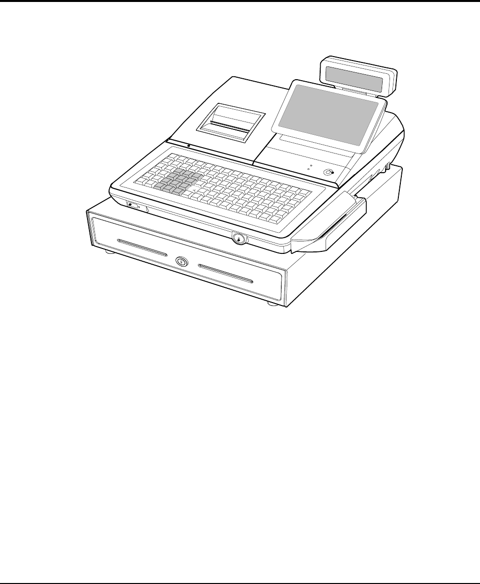
2-2-2 Location Features
Figure2-2 Location Features
400(W) : With G-Drawer
420(W) : With H-Drawer
① Printer Cover
② SD Card
③ Key Board
④ USB
⑤ Drawer
⑥ Customer LCD Display (16char*2line LCD)
⑦ Operator LCD Display(9.7” LED Panel 1024*768)
⑧ Mode Key
⑨ MSR
⑩ Dallas Key (i-BUTTON)
2 Product Specifications
SAM4S SAP-630 SERIES 2-3
2-3 Thermal Printer Specifications
2-3-1 Printer Specification (3”)
Item Description Remark
Model LTPF347E SII
Print Method Thermal Line Printing
Printing Format
Total Number of Dots 576 Dots / I Line
Dot Pitch
Vertical : 0.125 mm
Horizontal : 0.125 mm
Printing Speed 100 mm/Sec
Printing Direction Unidirectional Friction Feed
Paper Feeding
Feeding Method Friction Feed
Minimum Feed Pitch 0.0625 mm
Feeding Speed 100 mm/Sec
Power Supply Volt
Power Voltage 24V/24V (Recommend) Head/Motor
Circuit Input Voltage 5V Head Control/Sensor
Printer Head
Heat Element Density 8 Dots/mm (200dpi)
Total Head Elements 576 Dots/Dot Line
Available Printing Width 72 mm
Heat Element Typical Ω 1500 Ω ±3%
Line Feed Motor 4-Phase Bi-Polar Stepping Motor
Sensor
Head Temperature Thermistor
Paper-End Sensor Reflecting Photo Sensor
Printer Cover Open Sensor Micro Switch
Auto Cutter Type Guillotine Type SII
Reliability
TPH 100Km , 1×10⁸ Pulses
Auto-cutter 1,000,000 Cuts
Paper : PD-160R-N
(Oji paper co.,Ltd)
Dimension (mm) 110.2 (W) ×54 (D) ×25.8 (H)
Weight Approx. 175 g
Table2-2 Thermal Printer Specifications
2 Product Specifications
2-4 SAM4S SAP-630 SERIES
2-3 Thermal Printer Specifications
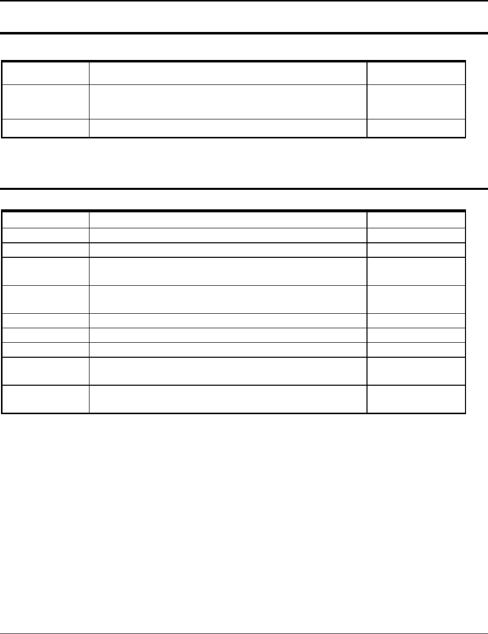
2-3-2 Paper Specification
Item Description Remark
Paper Type Single-ply Thermal Paper Roll
Paper Size 79.5 mm±0.5 mm (Width) ×80 mm or less
Specified Paper Original Paper No : HPK-110 (Hansol paper XT)
Table2-3 Paper Specification
Note: The following paper can be used instead of the specified paper above.
TF50KS-E: Nippon paper industries Co.,Ltd.
PD 160R : New Oji paper Mfg, Co.,Ltd.
F380 : Kansaki specialty papers, Inc. (USA)
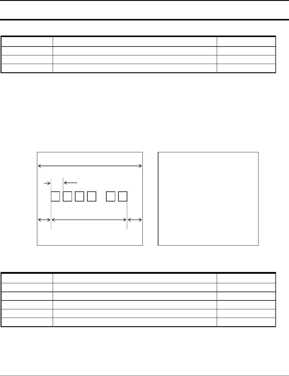
2-3-3 Printable Area
The Printable area of a paper with width of 79.5mm is 72.0mm(576 dots) and the space on the right and left
sides are approximately 4.0mm.
Figure2-3 Printable Area
2-3-4 Character Specification
Item Description Remark
Character Structure 12(W) × 24(H) Font (Including a Horizontal)
Character Size 1.25 mm(W) ×3.0 mm(H)
Column Pitch 1.5 mm
Line Pitch 3.75 mm (Including 6-dot Line Spacing)
Number of Column 32 (12×24 Dots/Character)
Table2-4 Character Specification
b
c d e
a
a = 79.5±0.5
mm
(Paper Width)
b = 0.141
mm (
1 Dot
)
c = 72.0
mm
(576 Dots/Printable Area)
d = 4.0
mm
(Left Space)
e = 4.0
mm
(Right Space)
2 Product Specifications
SAM4S SAP-630 SERIES 2-5
2-4 Power Specifications
2-4-1 Power Specification
Item Description Remark
Input Voltage &
Current
AC 100~240V, 800mA, 50/60Hz (Min : 90V, Max : 264V)
[AC/DC Adaptor(24V/2.5A) Internal]
Power Consumption Peak : 50W
Table2-5 Power Specification
2-5 Interface Specifications
2-5-1 RS-232C Serial Interface Specification
Item Description Remark
Data Transmission Serial Data Transmission
Synchronization Asynchronous
Hand Shaking
(Flow Control)
H/W : CTS / RTS
S/W : XON / XOFF
XON : ASC Code 11h
XOFF : ASC Code 13h
Signal Level
Logic”1” (MARK) : -3V ~ -15V
Logic”0” (SPACE) : +3V ~ +15V
Baud Rate 2400 / 9600 / 19200 / 38400 / 57600 / 115200 bps
Data Word Length 7 Bit / 8 Bit
Parity None / Even / Odd
Connector
DB9P Male : COM#1, COM#2
RJ-45 Modular Jack : COM#3, COM#4
Voltage Supply
VCC(+5V/1A):COM#1~#4
VCC(+5V/1A):USB#1~#2
Table2-6 RS-232C Serial Interface Specification
CAUTION :
“VCC” is supplied for the Barcode or other devices. Supply current 1A is total value including COM#1~COM#4.
If the Total Power Consumption exceeds specification (1A), the system cuts “VCC” of COM#1~COM#4.
“VCC “ is supplied for the USB Device. Supply current 1A is total value including USB1#~USB#2.
If the total Power Consumption exceeds specification (1A), the system cuts “VCC” of USB#1~USB#2.
2 Product Specifications
2-6 SAM4S SAP-630 SERIES
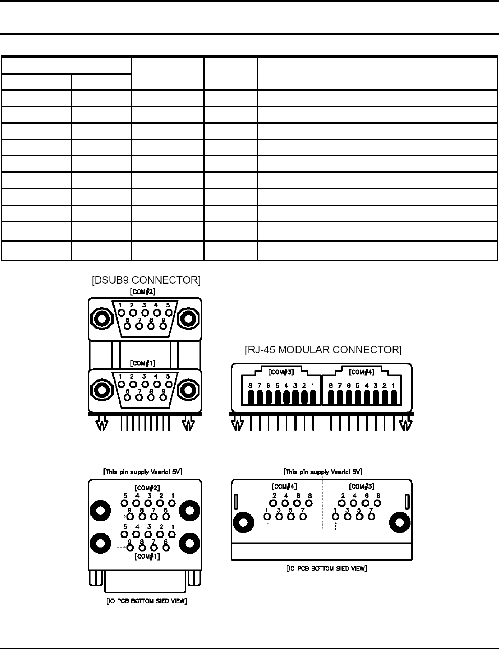
2-5 Interface Specifications
2-5-2 RS-232C Signal Description
PIN NO Signal Name Direction Function
DSUB9 RJ45
1 - DCD IN Carrier Detect
2 4 RXD IN Receive Data
3 3 TXD OUT Transmit Data
4 DTR OUT Data Set Ready
5 7 GND - -
6 DSR IN Data Terminal Ready
7 8 RTS OUT Request To Send
8 2 CTS IN Clear To Send
RI IN Ring Indicator
9 1 +5V/500mA - Total Power : 1A (COM#1,#2 : Pin9, COM#3,#4 : Pin1 )
-
2 Product Specifications
SAM4S SAP-630 SERIES 2-7
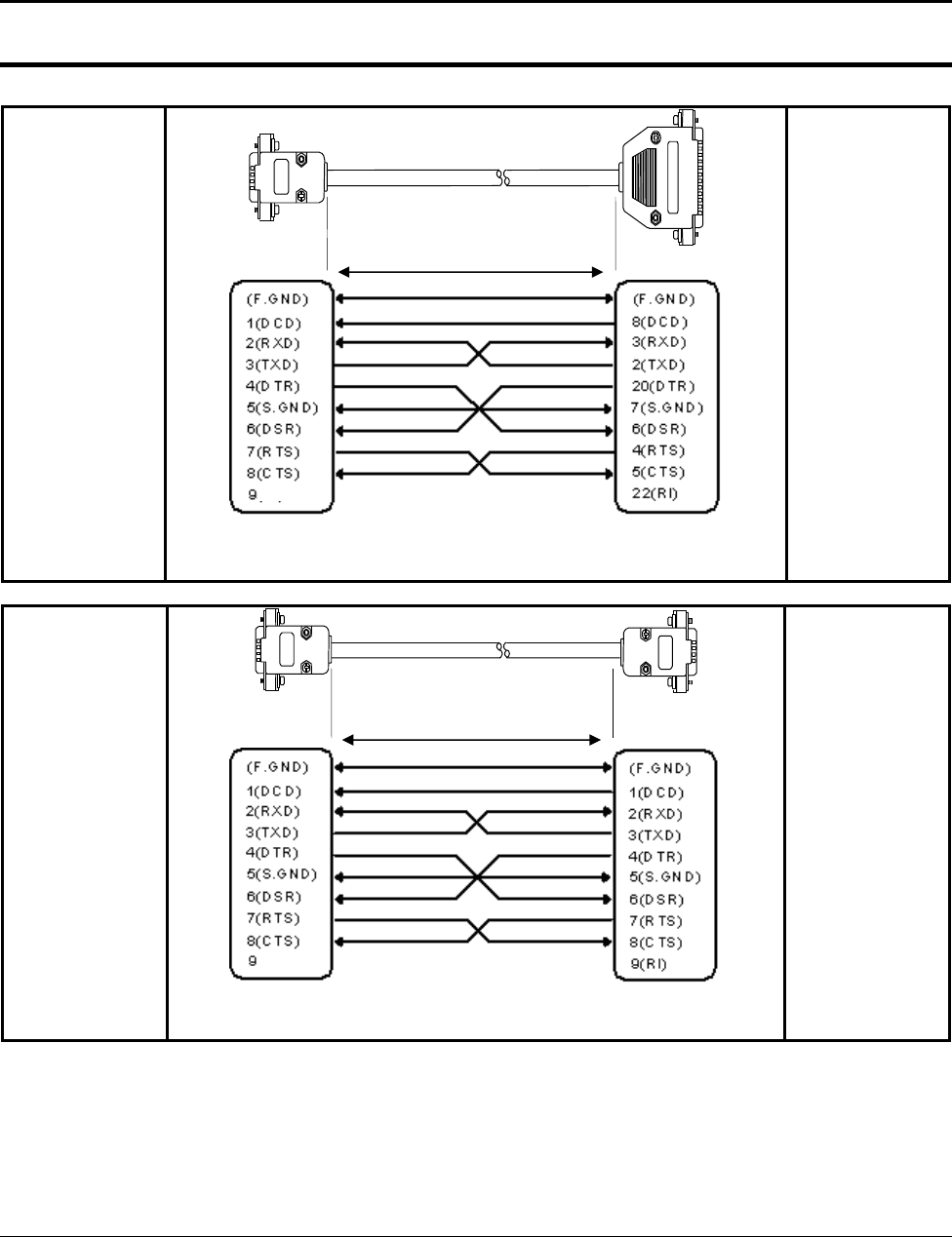
2-5 Interface Specifications
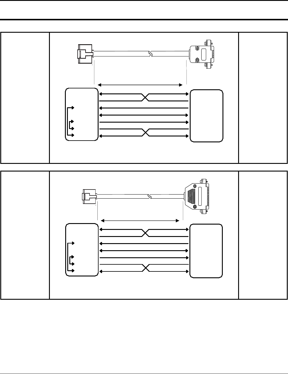
2-5-3 RS-232C Interface Cable (COM1, COM2)
SAP-630 SIDE
(DSUB9 FEMALE)
(+5 V)
( PIN CONNECTION )
USER SIDE
(DSUB25 MALE)
SAP-630 SIDE
(DSUB9 FEMALE)
(+5 V)
( PIN CONNECTION )
USER SIDE
(DSUB9 MALE)
CAUTION :
COM#1~COM#2 supplies “+5V” to DSUB9 “Pin Num 9”.
15m
15m
2 Product Specifications
2-8 SAM4S SAP-630 SERIES
2-5 Interface Specifications
2-5-3 RS-232C Interface Cable (COM3, COM4)
SAP-630 SIDE
(RJ-45 Modular)
5(RTS)
6(CTS)
3(TXD)
7(S.GND)
2(DSR)
7(RTS)
8(CTS)
5(S.GND)
3(TXD)
4(DTR)
8(DTR)
4(RXD)
6(DSR)
2(RXD)
( PIN CONNECTION )
USER SIDE
(DSUB9 MALE)
SAP-630 SIDE
(RJ-45 Modular)
5(RTS)
7(S.GND)
8(DTR)
3(TXD)
4(RXD)
4(RTS)
7(S.GND)
6(DSR)
2(TXD)
3(RXD)
6(CTS)
2(DSR)
5(CTS)
20(DTR)
( PIN CONNECTION )
USER SIDE
(DSUB25 MALE)
CAUTION :
COM#3~COM#4 supplies “+5V” to RJ45 “Pin Num 1”.
15m
15m
2 Product Specifications
SAM4S SAP-630 SERIES 2-9
2-5 Interface Specifications
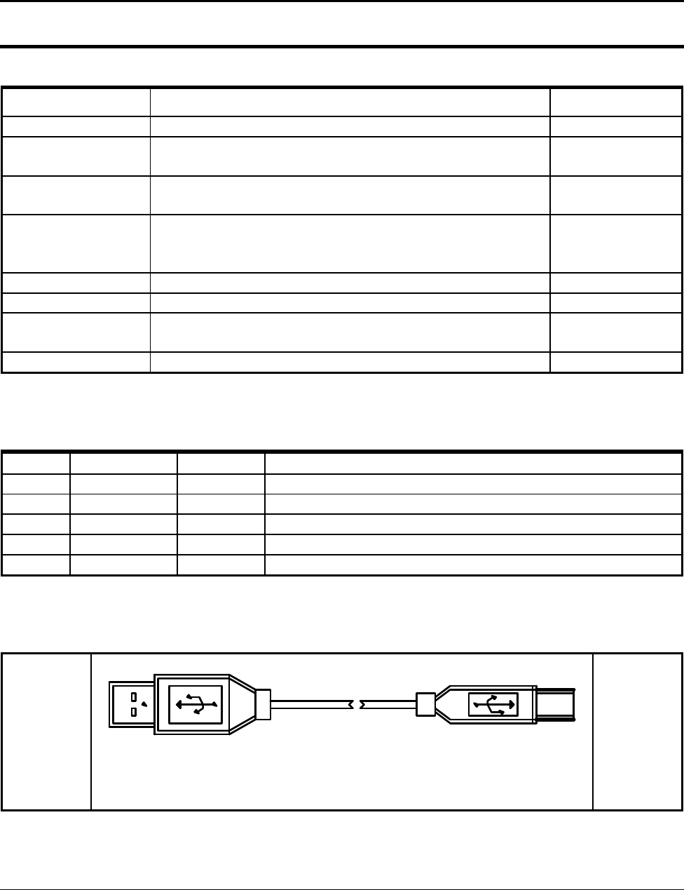
2-5-4 USB Interface Specification
Item Description Remark
Transfer Type ● BULK
Data Signal ● Bi-Direction, Half-Duplex
● Differential Signal Pair (D+ / D-)
Data Format ● NRZI Format
● Zero Bit Stuffing after 6 Ones
Transceiver
● Differential Common Mode Range : 0.8 ~ 2.5[V]
● Differential Receive Sensitivity : 200[mV]
● Single End Receive Threshold : 0.8 ~ 2.5[V]
Speed ● 480Mbps, 12Mbps
Power ● Supply 5V/500mA (For HID)
Cable & Connector ● Cable :5m/2m
● Connector :A type
Support Spec ● USB Spec Version 2.0
2-5-5 USB Signal Description
Pin No Signal Name Color Function
SHELL Shield Drain Wire Frame GND
1 VBUS Red Host Power : DC5[V] / 500[mA]
2 D- White Differential Data Line
3 D+ Green Differential Data Line
4 GND Black Signal GND
2-5-6 USB Interface Cable
SAP-630 SIDE
"A" TYPE PLUG "B" TYPE PLUG
( USB CABLE )
USER SIDE
2 Product Specifications
2-10 SAM4S SAP-630 SERIES
2-5 Interface Specifications
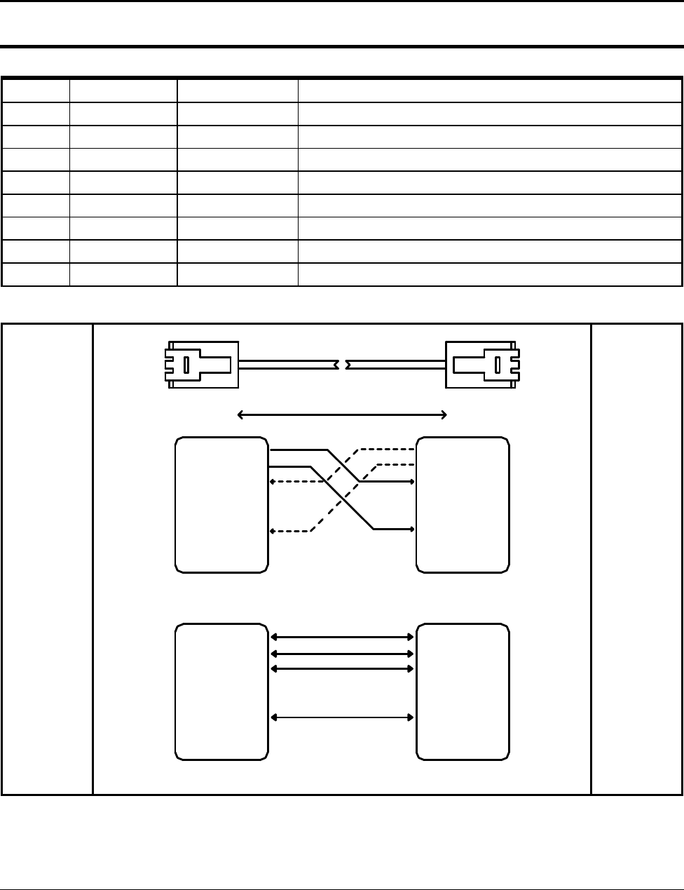
2-5-7 LAN (IRC) Signal Description
Pin No Signal Name Signal Direction Function
1 ENET TX+ OUT Ethernet Transmit Data Line(+)
2 ENET TX- OUT Ethernet Transmit Data Line(-)
3 ENET RX+ IN Ethernet Receive Data Line(+)
4 N.C -
5 N.C -
6 ENET RX- IN Ethernet Receive Data Line(+)
7 N.C -
8 N.C -
2-5-8 LAN (IRC) Interface Cable
SAP-630 SIDE
MAX 100M
5(N.C)
7(N.C)
8(N.C)
4(N.C)
5(N.C)
6(ENET RX-)
7(N.C)
1(ENET TX+)
2(ENET TX-)
3(ENET RX+)
6(ENET RX-)
1(ENET TX+)
2(ENET TX-)
3(ENET RX+)
4(N.C)
8(N.C)
( POS to POS IRC I/F CABLE )
7(N.C)
8(N.C)
6(ENET RX-)
7(N.C)
2(ENET TX-)
3(ENET RX+)
4(N.C)
6(ENET RX-)
4(N.C)
2(ENET TX-)
3(ENET RX+)
5(N.C)
1(ENET TX+)
8(N.C)
5(N.C)
1(ENET TX+)
( POS to HUB IRC I/F CABLE )
USER SIDE
2 Product Specifications
SAM4S SAP-630 SERIES 2-11
2-5 Interface Specifications
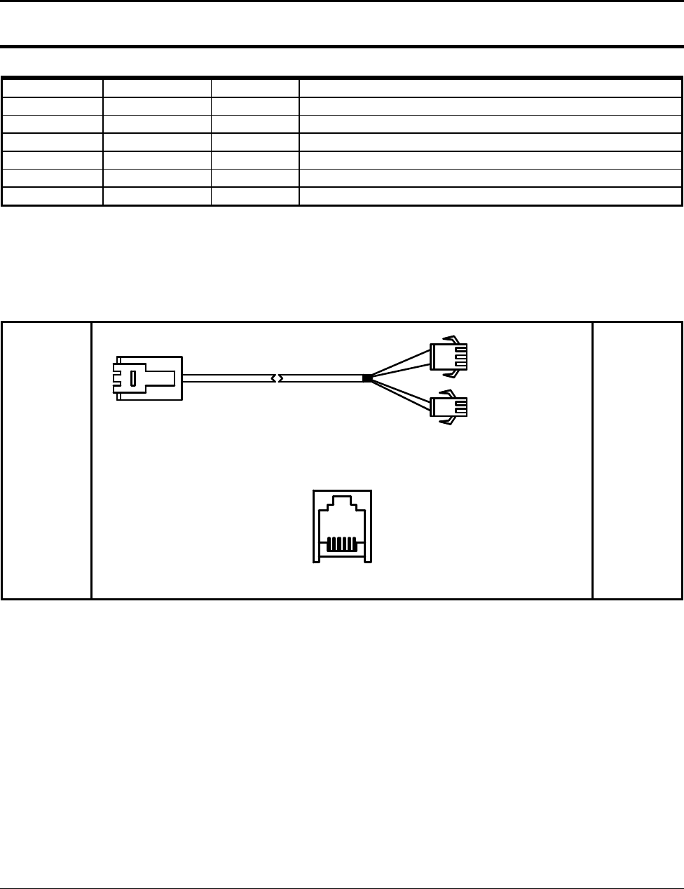
2-5-9 DRAWER Signal Description
Pin No Signal Name Direction Function
1 S.G - Signal GND
2 DRAWER#OUT OUT Drawer Kick-Out Driver Signal.
3 DRA_COMP IN Drawer Open / Close Signal
4 +24V - Supply DC +24[V]
5 DRAWER#OUT OUT Drawer Kick-Out Driver Signal.
6 F.G - Frame GND
CAUTION :
Make sure that installed “+24V Cash Drawer”.
Make sure that the Cash Drawer Solenoid Resistance is more than 20[Ohm]
2-5-10 DRAWER Interface Cable
SAP-630 SIDE
RJ11 6P COMPULSORY
DRAWER
(DRAWER I/F CABLE)
61
( DRAWER CONNECTOR )
USER SIDE
SAM4S SAP-630 SERIES 3-1
3 Installation and Operation
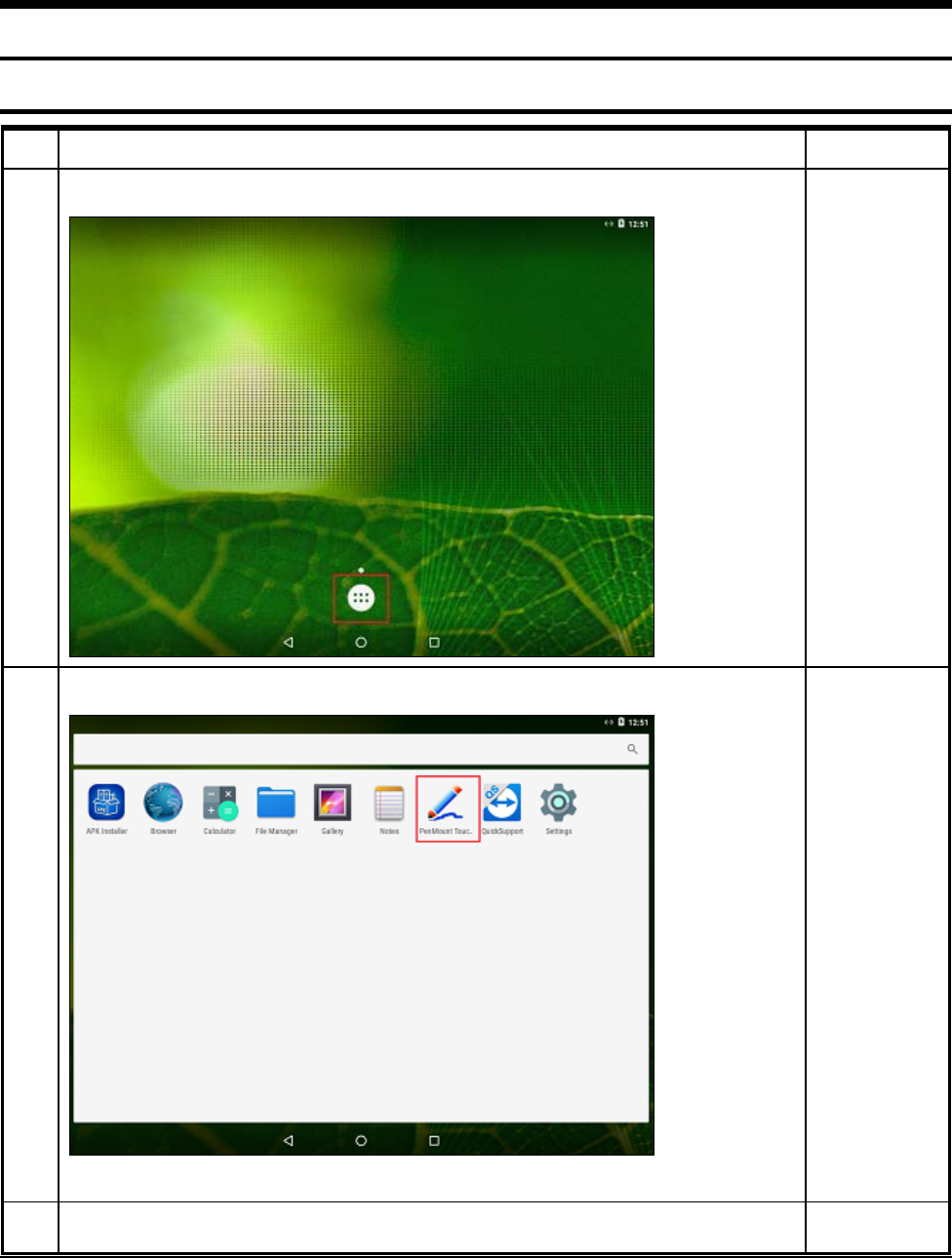
3-1 Touch Calibration
No Setup Method Remark
1
Click the menu
2
Click Touch Screen “APP”
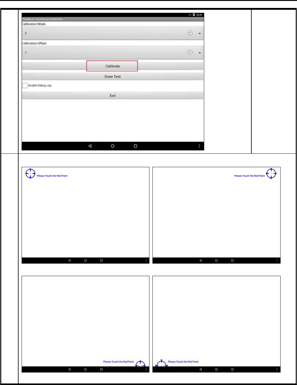
3 Click Calibration
3 Installation and Operation
3-2 SAM4S SAP-630 SERIES
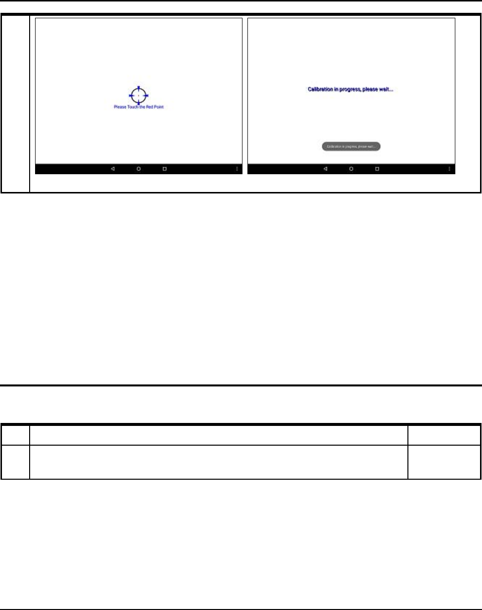
4
Follow below steps
3 Installation and Operation
SAM4S SAP-630 SERIES 3-3
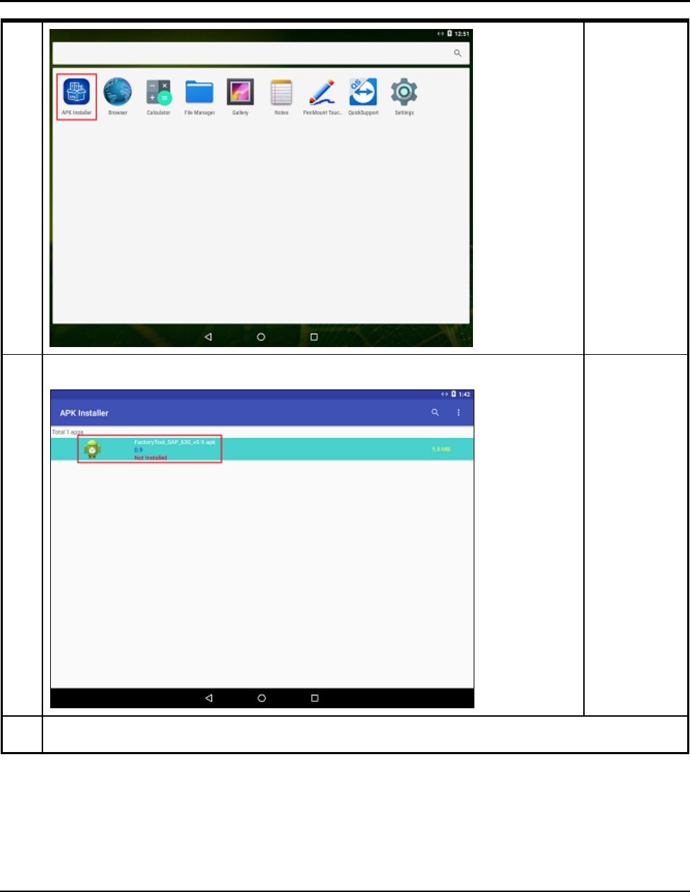
3-2 Application Management
3-2-1 Application INSTALL
No Setup Method Remark
1 Click “the APKInstaller”
3 Installation and Operation
3-4 SAM4S SAP-630 SERIES
2
Click “the APK”
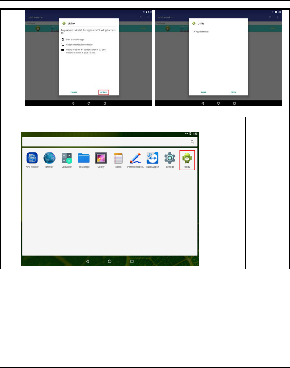
3 Click Install
3 Installation and Operation
SAM4S SAP-630 SERIES 3-5
4
You can check what is installed on the menu screen.
3 Installation and Operation
3-6 SAM4S SAP-630 SERIES
3-2 Application Management
3-2-2 Application UNINSTALL
No Setup Method Remark
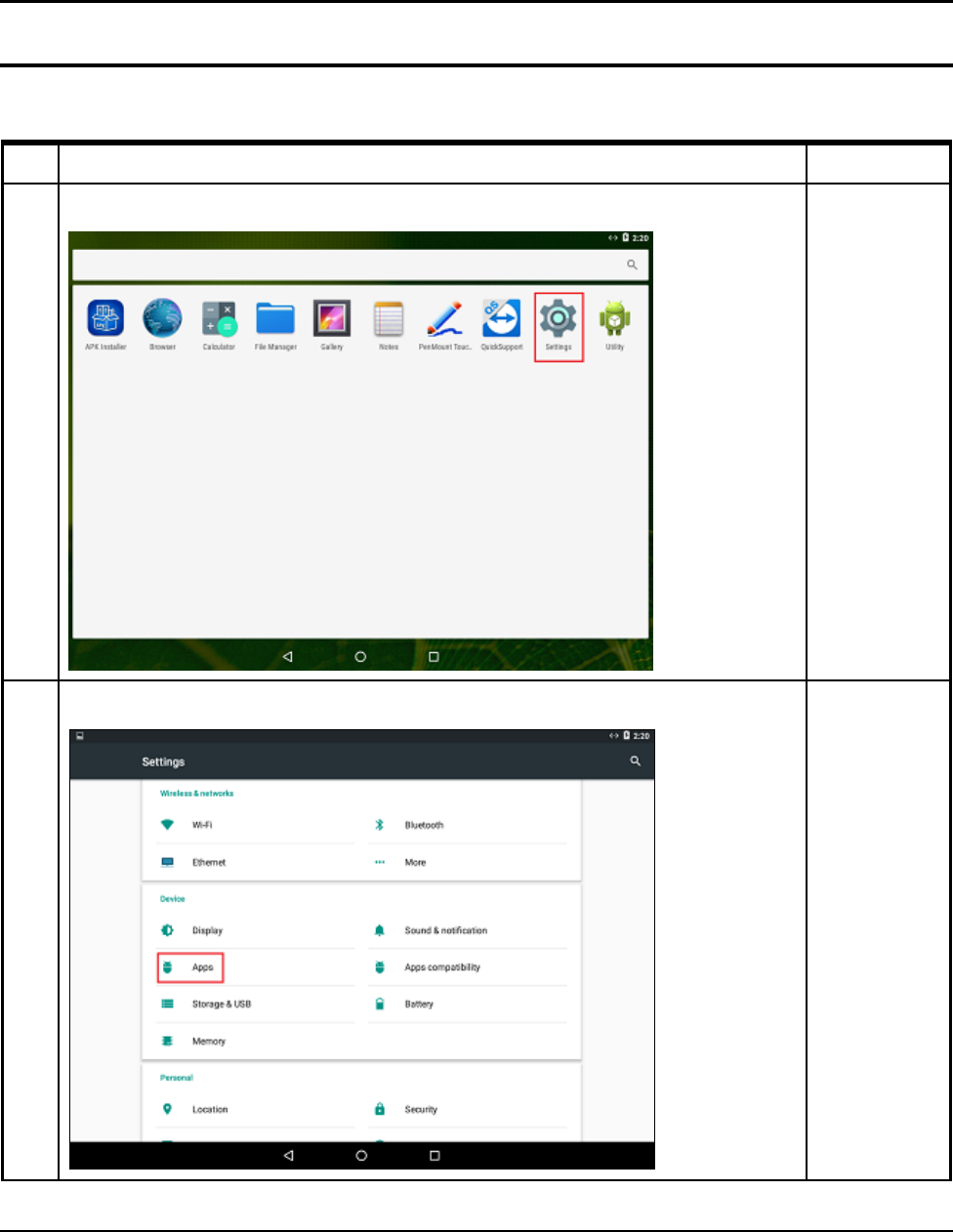
1
Click “Settings”
2
Click “the APK”
3 Installation and Operation
SAM4S SAP-630 SERIES 3-7
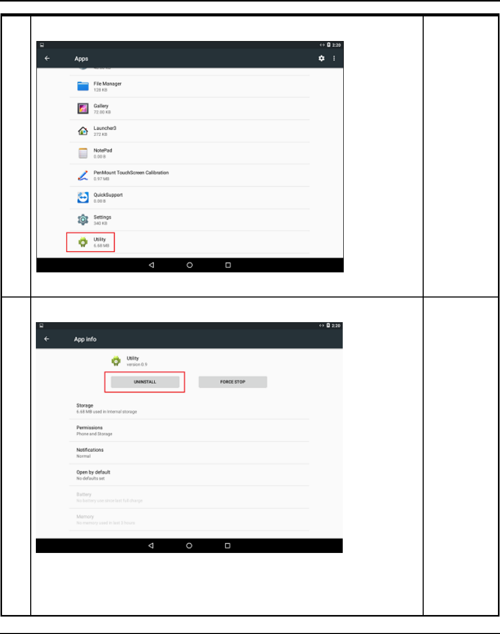
3
Click on the app you want to delete.
4
Click “UNINSTALL” button.
3 Installation and Operation
3-8 SAM4S SAP-630 SERIES
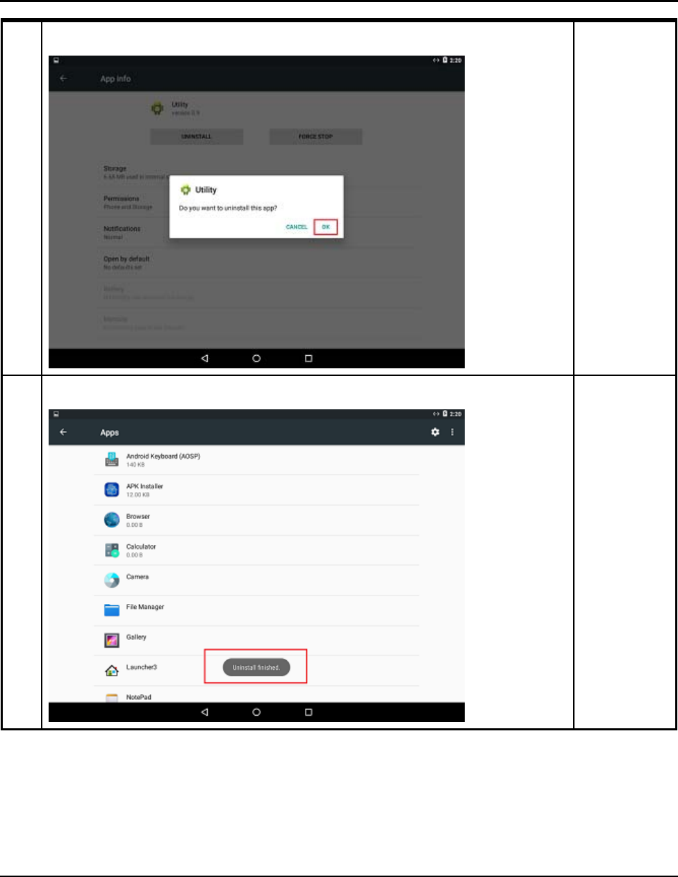
5
Click “OK”
6
You can check the success message.
3 Installation and Operation
SAM4S SAP-630 SERIES 3-9
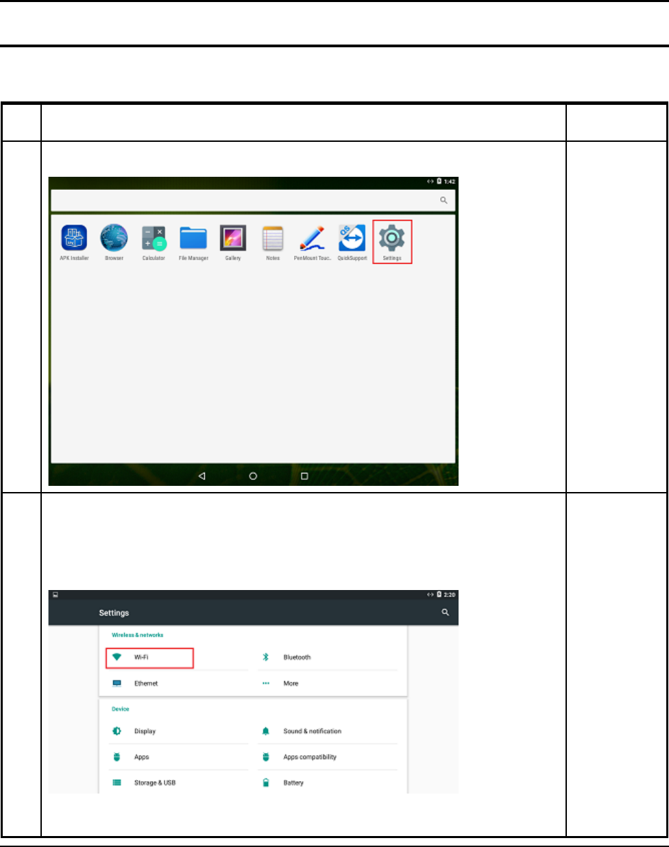
3-3 System Set Up
In the system user can setup according to their own requirements, such as network connection, language,
Input methods, Display brightness, Sound output and check storage space
No Setup Method Remark
1
Click Settings Icon.
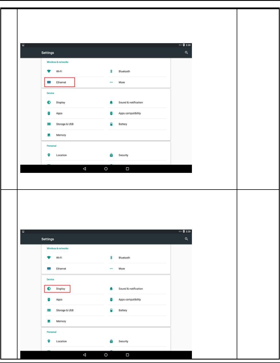
2
WIFI
When opened WIFI Setting would search available wireless router signals, user
j
ust select a router and input correct password then could browser internet. If
the router does not have password, WIFI would connect it directly
3 Installation and Operation
3-10 SAM4S SAP-630 SERIES
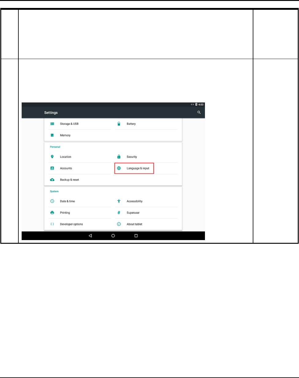
3
Ethernet
First, check box to turn on Ethernet, click “Ethernet” to choose connection
type.
4
Display
This is for Display setting;
Brightness: Click to setup brightness of backlight.
Font Size: Click to setup system font size according to their preference.
3 Installation and Operation
SAM4S SAP-630 SERIES 3-11
5
Language & Input
User can set the language for system menus according to their Country or
preference. (About 60 languages supported) System default support Chinese
and English, user need manual installing other input methods.
3 Installation and Operation
3-12 SAM4S SAP-630 SERIES
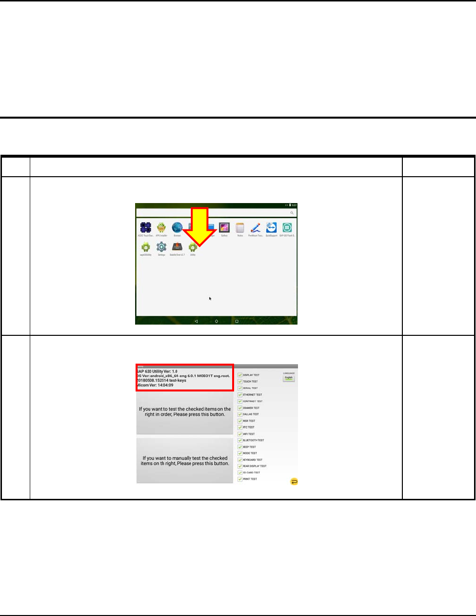
3-4 Hardware Self Test
3-4-1 INSTALL UTILITY
No Setup Method Remark
1
After Install “Utility Apk”
Click this APK
2
Check the F/W versions (OS & Micom)
3 Installation and Operation
SAM4S SAP-630 SERIES
3-13
3-4 Hardware Self Test
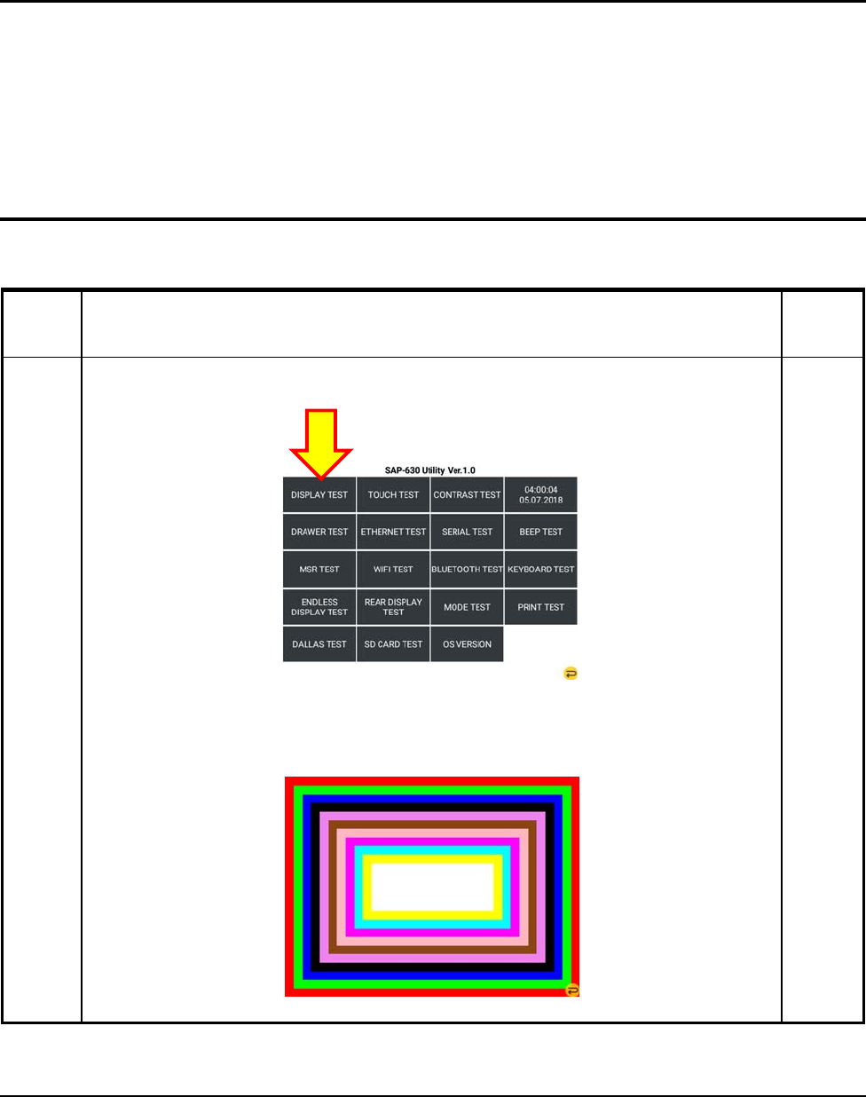
3-4-2 DISPLAY TEST
Test Method Remar
k
Display
TEST
Press “DISPLAY TEST” from the main menu in the Touch Screen.
.
Check the LCD State.(9.7inch LCD). You must touch the screen for test is done.
3 Installation and Operation
3-14 SAM4S SAP-630 SERIES
3-4 Hardware Self Test
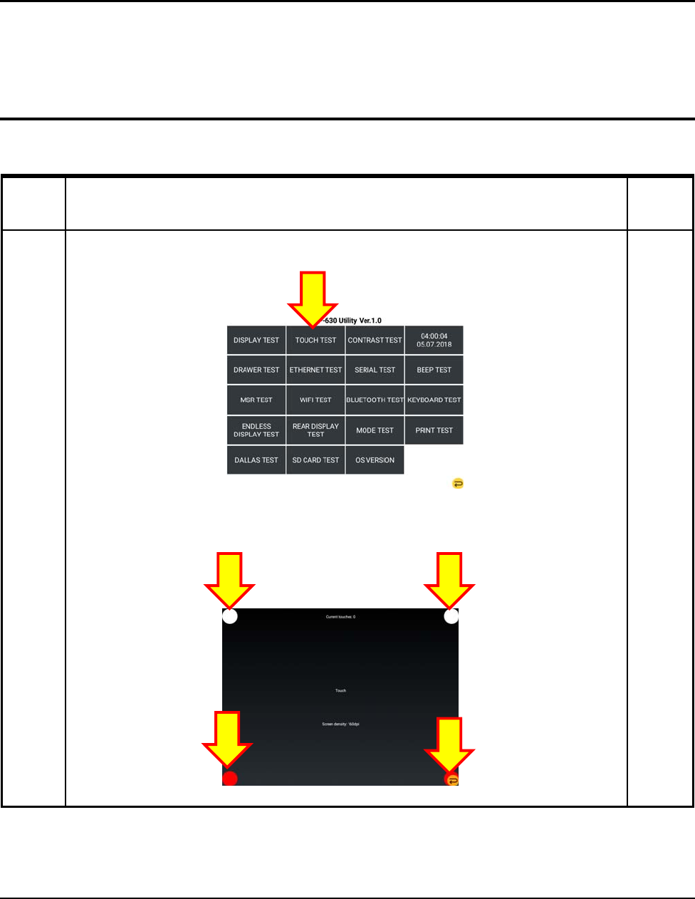
3-4-3 TOUCH TEST
Test Method Remar
k
Touch
TEST
Press “TOUCH TEST” from the main menu in the Touch Screen.
.
Touch the 4 Circles or Press and drag 4 Circles.
3 Installation and Operation
SAM4S SAP-630 SERIES 3-15
3-4 Hardware Self Test
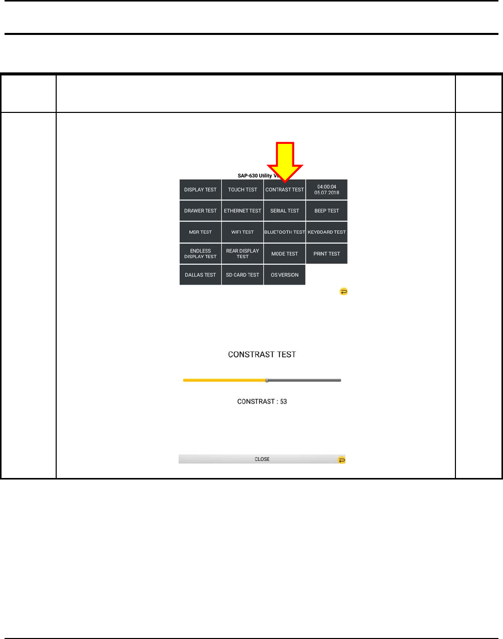
3-4-4 Contrast TEST
Test Method Remar
k
CONTRAST
TEST
Press “CONSTRAST TEST” from the main menu in the Touch Screen.
Adjust “Brightness”
3 Installation and Operation
3-16 SAM4S SAP-630 SERIES
3-4 Hardware Self Test
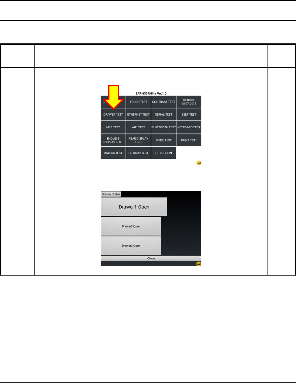
3-4-5 DRAWER Port TEST
Test Method Remar
k
DRAWER
TEST
Press “DRAWER TEST” from the main menu in the Touch Screen.
When DRAWER Open , DRAWER Status is changed
3 Installation and Operation
SAM4S SAP-630 SERIES 3-17
3-4 Hardware Self Test
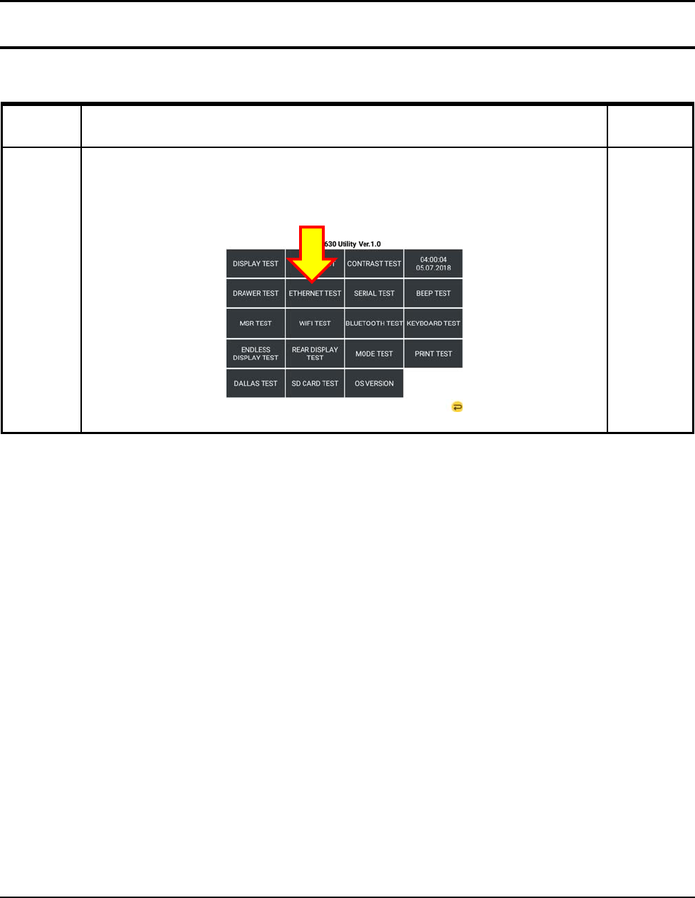
3-4-6 Ethernet TEST
Test Method Remark
Ethernet
TEST
Connect The UTP CABLE to Ethernet Port
Press “ETHERNET TEST” from the main menu in the Touch Screen.
3 Installation and Operation
3-18 SAM4S SAP-630 SERIES
3-4 Hardware Self Test
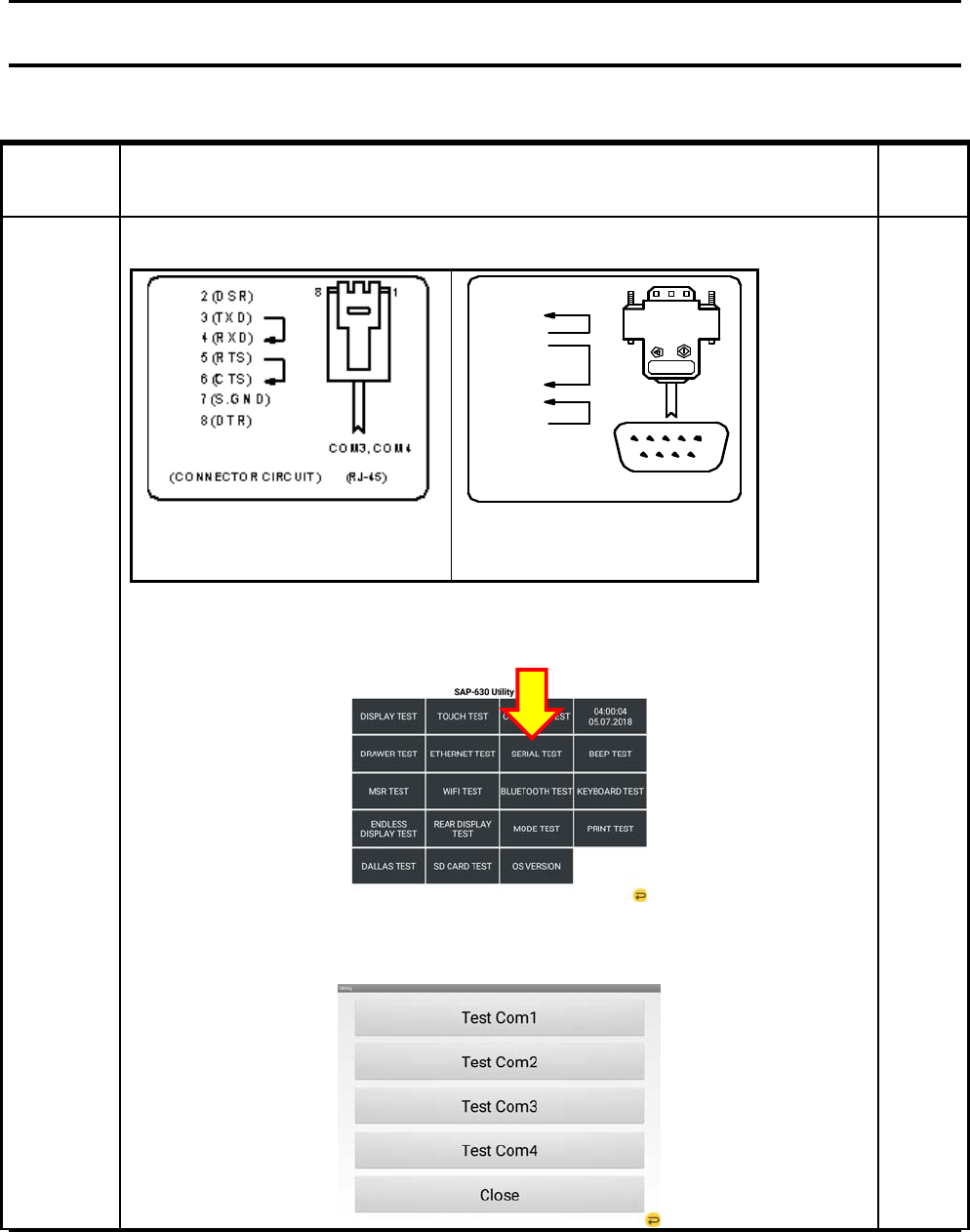
3-4-7 Serial Port TEST
Test Method Remar
k
SERIAL
PORT TEST
Connect Loop-back Test Connector to SERIAL Port
(RJ-45 Test Connector)
9(RI)
8(CTS)
6(DSR)
3(TXD)
1(DCD)
2(RXD)
5
96
1
7(RTS)
4(DTR)
(CONNECTOR CIRCUIT ) COM1,2 (MALE)
5(S.GND)
(DSUB9 Test Connector)
Press “SERIAL TEST” from the main menu in the Touch Screen.
Check the Port #1,#2,#3,#4
3 Installation and Operation
SAM4S SAP-630 SERIES 3-19
3-4 Hardware Self Test
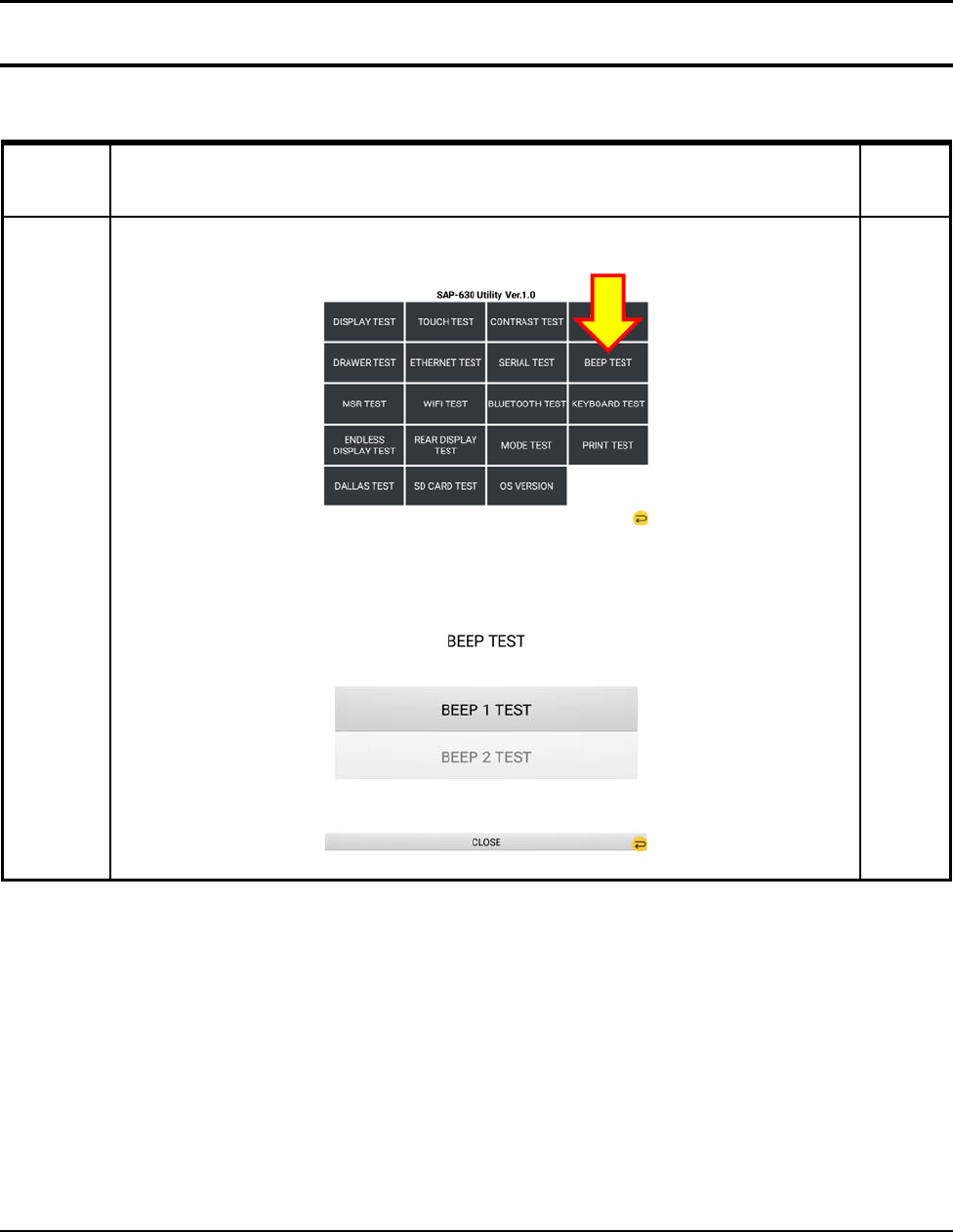
3-4-8 Beep TEST
Test Method Remar
k
BEEP TEST
Press “BEEP TEST” from the main menu in the Touch Screen.
Check the Beep #1, #2
3 Installation and Operation
3-20 SAM4S SAP-630 SERIES
3-4 Hardware Self Test
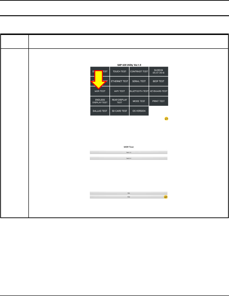
3-4-9 MSR TEST
Test Method
MSR TEST
Press “MSR TEST” from the main menu in the Touch Screen.
When you swipe a magnetic card, If you see the value of the card .Test is done.
3 Installation and Operation
SAM4S SAP-630 SERIES 3-21
3-4 Hardware Self Test
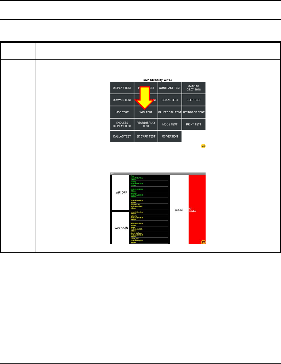
3-4-10 WIFI TEST
Test Method
WIFI TEST
Press “WIFI TEST” from the main menu in the Touch Screen.
Press WIFI ON button and then show the dbm.
3 Installation and Operation
3-22 SAM4S SAP-630 SERIES
3-4 Hardware Self Test
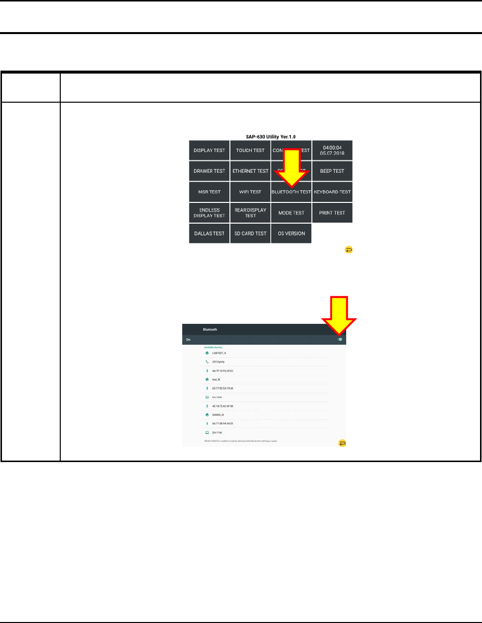
3-4-11 BLUETOOTH TEST
Test Method
BLUETOOTH
TEST
Press “BLUETOOTH TEST” from the main menu in the Touch Screen.
Press ON button and then show the list of devices.
3 Installation and Operation
SAM4S SAP-630 SERIES 3-23
3-4 Hardware Self Test
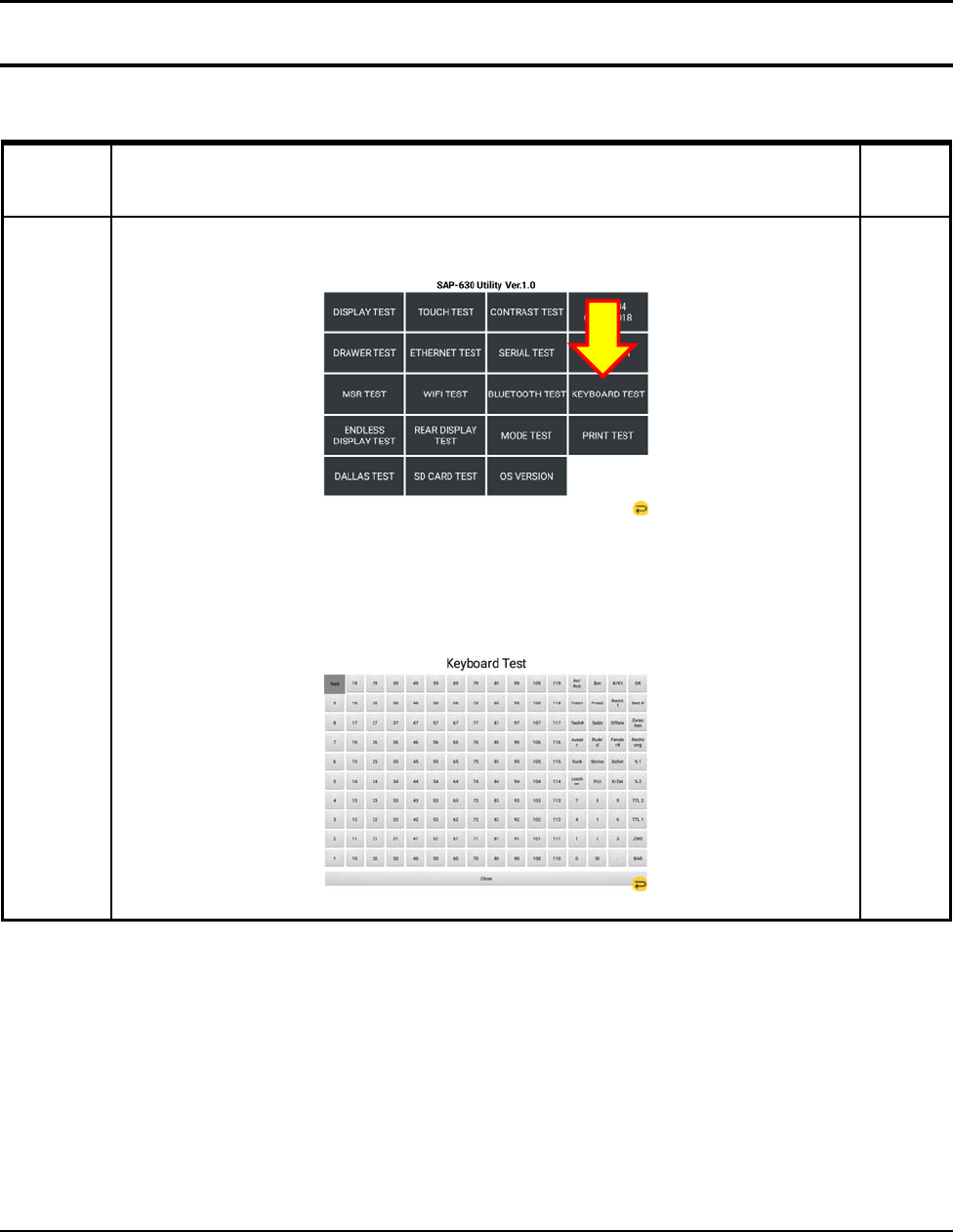
3-4-12 KEYBOARD TEST
Test Method Remar
k
KEYBOARD
TEST
Press “KEY BOARD TEST” from the main menu in the Touch Screen.
Press “KEY BOARD 160KEY” on Keyboard. When You press Keys, Button is changed to black
Test is done.
3 Installation and Operation
3-24 SAM4S SAP-630 SERIES
3-4 Hardware Self Test
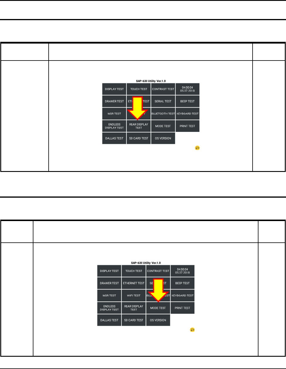
3-4-13 REAR DISPLAY TEST
Test Method Remark
REAR DISPLAY
TEST
Press “REAR DISPLAY TEST” from the main menu in the Touch Screen.
Check the Rear Display(2Line LCD).
3-4 Hardware Self Test
3-4-14 MODE TEST
Test Method Remar
k
MODE
TEST
Press “MODE TEST” from the main menu in the Touch Screen.
When the key is turned ,If you see the all testing mode value, test is done
3 Installation and Operation
SAM4S SAP-630 SERIES 3-25
3-4 Hardware Self Test
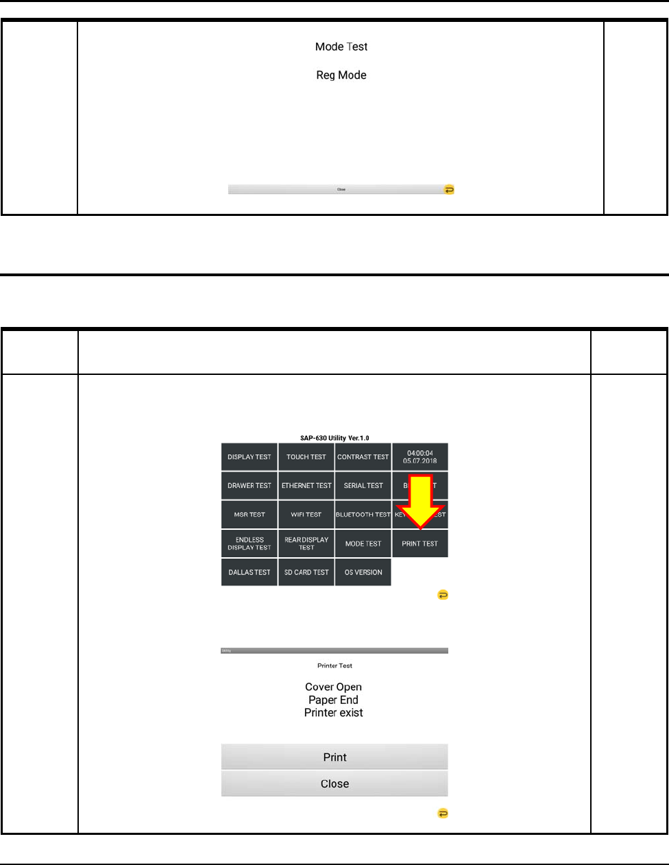
3-4-15 Printer TEST
Test Method Remark
PRINTER
TEST
Press “MODE TEST” from the main menu in the Touch Screen.
Press “PRINTER” from the main menu in the Touch Screen.
Click the Print button.
Open the Print Cover and then show the Error messages.
3 Installation and Operation
3-26 SAM4S SAP-630 SERIES
3-4 Hardware Self Test
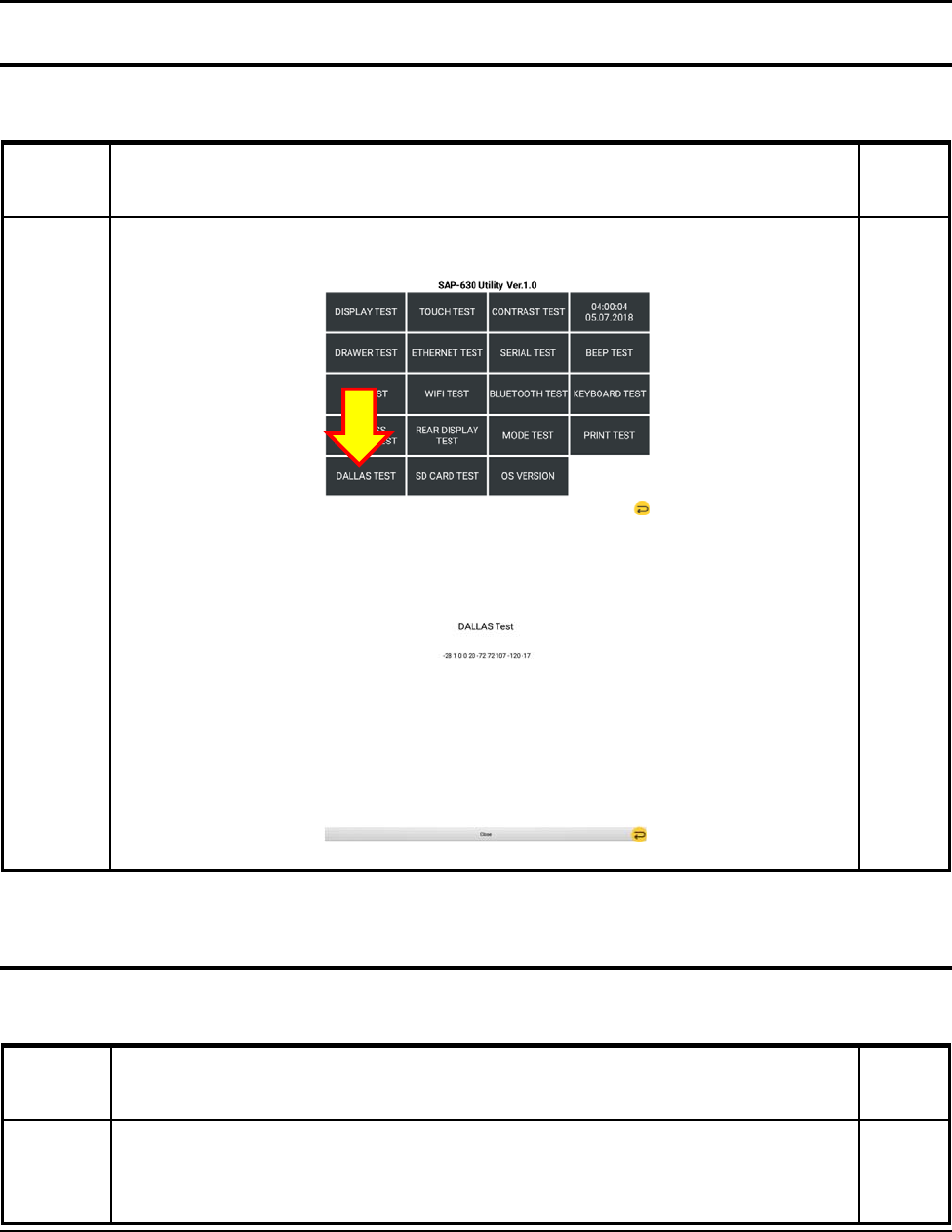
3-4-16 DALLAS TEST
Test Method Remar
k
DALLAS
TEST
Press “DALLAS TEST” from the main menu in the Touch Screen.
When You connect Dallas key to Dallas module, You can see the numbers on Screen.
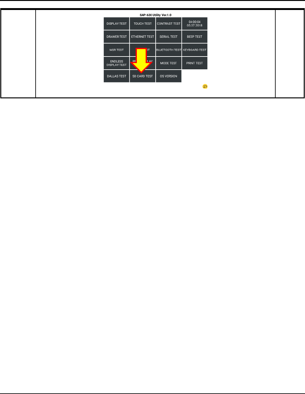
3-4 Hardware Self Test
3-4-17 SD CARD TEST
Test Method Remar
k
SD CARD
TEST
Insert SD Card
Press “SD CARD TEST” from the main menu in the Touch Screen.
3 Installation and Operation
SAM4S SAP-630 SERIES 3-27
3 Installation and Operation
3-28 SAM4S SAP-630 SERIES
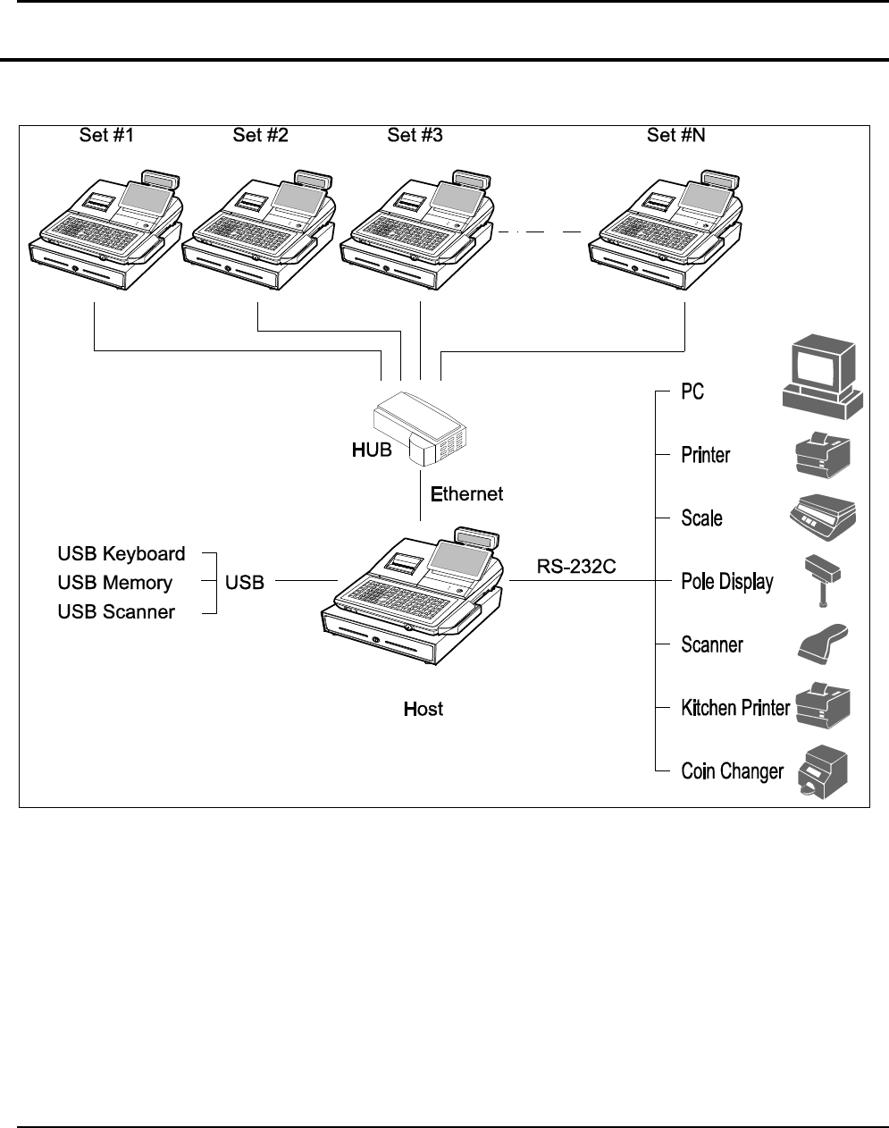
3-5 System Configuration
3-5-1 Configuration
Figure 3-1 System Configuration
3 Installation and Operation
SAM4S SAP-630 SERIES 3-29
3-6 Installation
3-6-1 Options
No. Item Description Remark
1 Dallas Key 5EA, 10EA, 15EA Selectable
2 Water Proof Default
3 MSR 1Slot
Table 3-1 Option
3-6-2 Supplies
No. Item Description Remark
1 Paper Roll 1EA
2 Mode Key VD, REG, X, Z, P, C
3 User Manual 1 EA
Table 3-2 Supplies
3 Installation and Operation
3-30 SAM4S SAP-630 Series
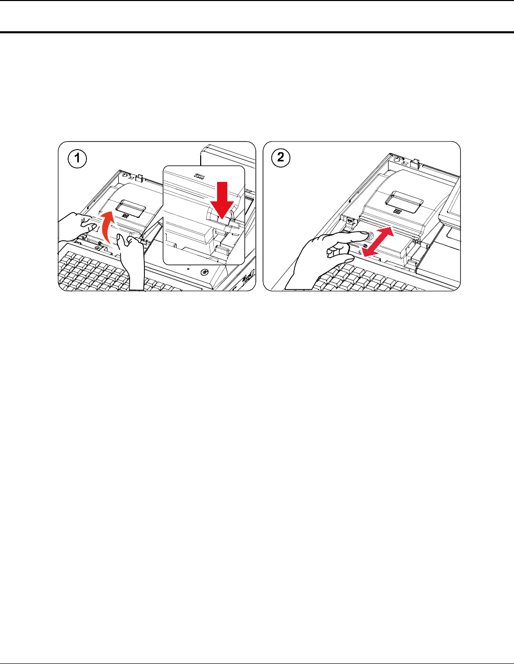
3-7 Installation
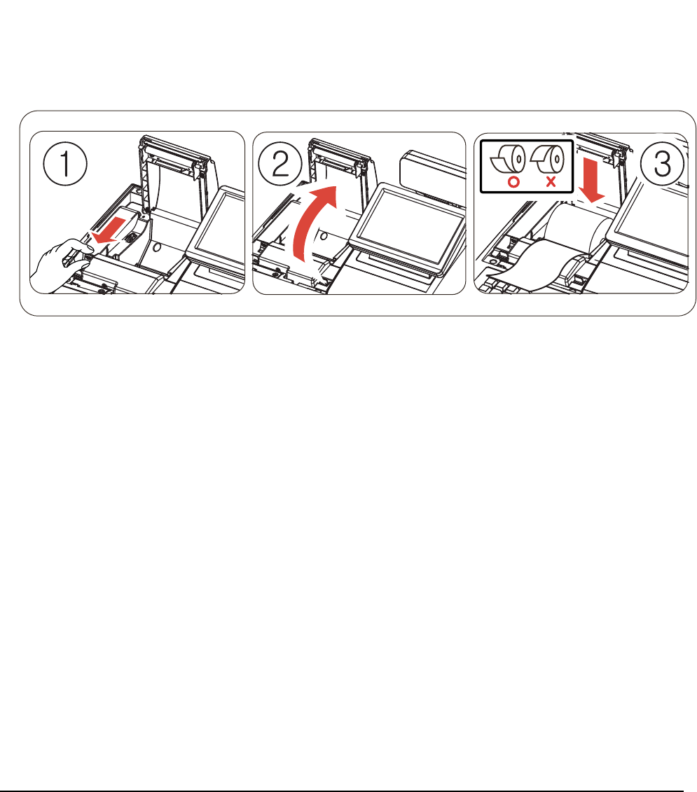
3-7-1 Paper Roll Installation
1. Open the cover printer.
2. Pulling the Orange Lever will open paper cover in Figure3-2-①.
3. Ensure that the paper is being fed from the bottom of the roll. Place the roll into the concave bottom of the
printer. And put the leading edge of the paper over the printer in Figure3-2-②.
4. Close the printer cover slowly until it locks firmly.
5. Tear off the excess paper.
Figure 3-2 Paper Installation
3 Installation and Operation
SAM4S SAP-630 SERIES 3-31
3-7 Installation
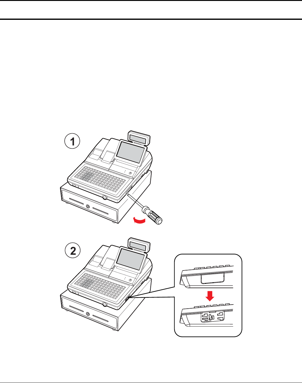
3-7-2 Installation of MSR Assembly
Caution :
ꞏ Before installation, be sure to turn off the power switch.
ꞏ Use gloves to protect your hand from being cut by the angle and the chassis.
ꞏ Connect all the cables correctly. When connecting or disconnecting the cables, be careful not to apply
stress to the cables. (It may cause disconnection)
ꞏ Be careful not to bind interface cables and AC power cord together.
1. Cut off the area (MSR assembly area) shown in the Figure 3-3-○
1 by using a (-) shaped screw driver.
2. Figure 3-3-○
2 shows the difference before and after.
Figure 3-3 MSR Installation (1)
3 Installation and Operation
3-32 SAM4S SAP-630 SERIES
3-7 Installation
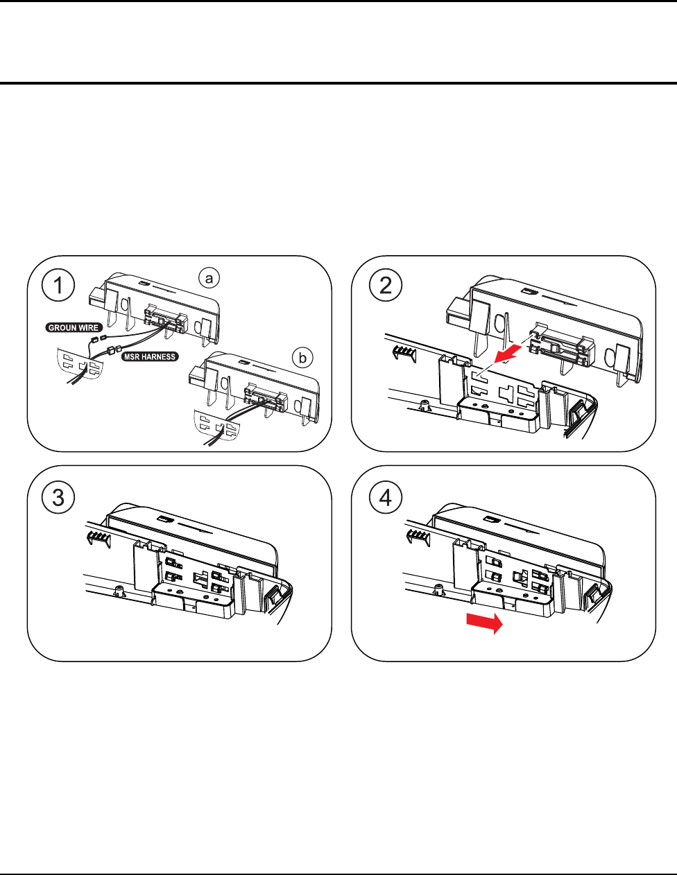
3-7-3 Installation of MSR Assembly
1. Connect Ground Wire & MSR Harness of MSR Assembly to the main set as shown in Figure 3-4-○
1-○
a.
2. Tidy up the connectors of Ground Wire & MSR Harness by inserting them into the MSR Assembly
(Connectors should be hidden inside the MSR Assembly), Figure 3-4-○
1-○
b.
3. Insert MSR Assembly into the main set bracket holes as in Figure 3-4-○
2, Figure 3-4-○
3.
4. Tighten MSR Assembly by moving it to the direction shown in Figure 3-4-○
4.
Figure 3-4 MSR Installation (2)
3 Installation and Operation
SAM4S SAP-630 Series 3-33
3-7 Installation
3-7-4 Installation of MSR Assembly
1. Figure 3-5 shows the MSR Assembly is in position
Figure 3-5 MSR Installation (3)
3 Installation and Operation
3-34 SAM4S SAP-630 SERIES
3-8 Operation
Note: Before using this POS for the first time, leave it powered ON in the REG mode for at least 24 hours. This
allows the MS-Lithium Rechargeable battery, which maintains the POS’s memory while the power is OFF,
to fully charge.
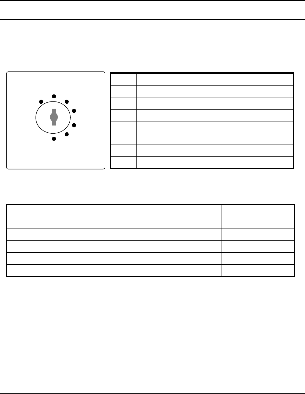
3-8-1 Mode Switch
The position of the Mode Switch determines the action of the POS. The modes are described in Table 3-3
Mode Key Function
VOID VD Use to void (correct) items outside of a sale.
OFF - The Register is inoperable.
REG REG Used for normal registrations.
X X Used to read register reports and perform other manager
functions.
Z Z Used to read register reports and reset totals to zero.
P P Used to program the register
S C Used for H/W tests and special setting.
Figure3-6 Mode Switch Table3-3 Mode Switch Function
The mode keys can be used to access the following key lock positions.
Mode Accessible Position Remark
VOID Void, Off, Register, Manager
X Off, Register, Manager
Z Off, Register, Manager, Clear Totals
PGM Void, Off, Register, Manager, Clear Totals, Program
S Void, Off, Register, Manager, Clear Totals, Program, Service Mode
Table3-4 Key Function
Note : Key can be removed from the key lock in the OFF or REG position.
REG
X
Z
P
S
OFF
V
OID

SAM4S SAP-630 SERIES 4-1
4 Disassembly and Assembly
Caution :
· Before installation, be sure to turn off the power switch.
· Use gloves to protect your hand from being cut by the angle and the chassis.
· Connect all the cables correctly. When connecting or disconnecting the cables, be careful not to apply
stress to the cables. (It may cause disconnection)
· Be careful not to bind interface cables and AC power cord together.
4-1 Disassembling the Case Upper Block
4-1-1 Ass’y Case Upper
1. Open the ASS'Y COVER PRINTER(B) and lift it off. (Page7-1)
2. Remove the five screws(C19:4pcs, C20:1pcs) from the ASS'Y CASE LOWER(G). (Page7-4)
3. Separate the two harnesses(ⓑ,ⓗ) from the INTERFACE BRKT(G-28). (Page7-11)
5. Lift off the ASS'Y CASE UPPER(C) from the ASS'Y CASE LOWER(G). (Page7-1)
4-1-2 Ass’y Front LCD Display
1. Separate the ASS'Y LCD DISPLAY(A) from the ASS'Y CASE UPPER (C). (Page7-1)
2. Remove the two CAP RUBBER(A-17) on the ASS’Y LCD DISPLAY(A).(Page7-2)
3. Remove the two screws(A-16) on the ASS’Y CASE UPPER(C). (Page7-2)
4. Remove the four screws(A-15) on the LCD HOLDER(A-14) and separate the LCD HOLDER(A-14).
5. Remove the four screws(A-13) on the LCD REAR(A-12) and separate the LCD REAR(A-12).(Page7-2)
6. Remove the six screws(A-9) from the BRKT LCD(A-6) and separate the LCD FRONT(A-1).(Page7-2)
7. Separate the TOUCH PANEL(A-3) and DISPLAY-LCD(A-5) from the BRKT LCD(A-6). (Page7-2)
4-1-3 Ass’y Rear Display
1. Separate the ASS'Y TURRET from the ASS'Y CASE UPPER (C). (Page7-4)
2. Remove the screw(C-28) on the TURRET REAR(C-27) . (Page7-4)
3. Separate the TURRET REAR(C-27) and remove the two screws(C-26). (Page7-4)
4. Separate the UNIT-REAR DISPLAY (C-24) from the TURRET FRONT(C -22). (Page7-4)
4-1-4 Ass’y Cover Mode Switch
1. Separate the ASS'Y COVER MODE S/W from ASS'Y CASE UPPER(C). (Page7-4)
2. Remove the four screws(C-14 and C-18) on the ASS'Y COVER MODE S/W and separate the ASS'Y
SWITCH ROTARY (Reference:C-15), LED BOARD(C-13) from the COVER MODE S/W(C-11). (Page7-4)
3. Remove the two screws(C-17) on the ASS'Y SWITCH ROTARY(Reference:C-15) and separate
the BRKT MODE SWITCH(C-16) and the SWITCH ROTARY (C-15). (Page7-4)
4. Separate the two harnesses(ⓒ,ⓘ) from the MOTHER BOARD(G-37). (Page7-11)

4 Disassembly and Assembly
4-2 SAM4S SAP-630 SERIES
4-2 Disassembling the Case Lower Block
4-2-1 Ass’y Printer
1. Open the ASS'Y COVER PRINTER(B) and lift it off. (Page7-1)
2. Separate the GROUND(ⓙ andⓛ) from the ASS'Y CASE LOWER(G). (Page7-6,Page7-11)
3. Remove the two screws(G-7) from the ASS'Y CASE LOWER(G). (Page7-11)
4. Separate the ASS'Y PRINTER from the ASS'Y CASE LOWER(G). (Page7-11)
4-2-2 Ass’y key Board
1. Separate the two FPC cables from the MOTHER BOARD(G-37).
And then lift off the ASS’Y KBD(E or F).(Page7-11)
4-2-3 Ass’y Dallas Key
1. Disconnect the Harness of the ASS’Y DALLAS KEY(G-5) from the MOTHER BOARD(G-37).(Page7-11)
2. Lift up the ASS'Y DALLAS KEY.
3. If don’t use it, only lift up COVER FRONT(G-6) from the ASS'Y CASE LOWER(G).(Page7-15,Page7-11)
Note
There are three types in DALLAS KEY; ADDIMAT KEY, DALLAS KEY or ADDIMAT KEY
4-2-4 Ass’y MOTHER BOARD
1. Separate the six harnesses(ⓒ,ⓘ,ⓜ,ⓝ,ⓡ,ⓢ) and remove the six screws(G-38:5pcs,G-42:1pcs).
Separate the MOTHER BOARD(G-37).(page7-11)
4. Remove the one screw(G-43) and separate the PLATE SHIELD(G-35) from the ASS’Y LOWER(G). (page7-11)
4-2-5 Ass’y USB BOARD
1. Remove the one screw(G-12) and separate the harnesses(n) from the MOTHER BOARD(G-37).(Page7-11)
Lift up the USB BOARD(G-11).(Page7-11).2.
2. Remove the one screw(G-40) and separate the Wifi/Bluetooth module from the MOTHER BOARD(G-37).
3.
SAM4S SAP-630 SERIES 5-1
5 Maintenance and Adjustment
5-1 Maintenance
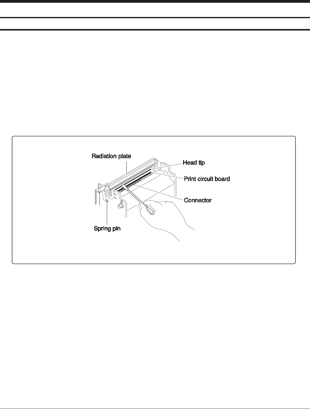
5-1-1 Cleaning the Printer Head
Paper dust on the heating elements may lower the print quality. In this case, clean the print head as follows:
After printing, the printer head can be very hot.
Be careful not to touch it.
Also let it cool before you clean it.
Do not damage the printer head by touching it with your fingers or any hard object.
1. Turn the POS System power switch off.
2. Open the Printer Cover.
3. Open the cover of paper supplier with pushing the ORANGE CAP LEVER.
4. Clean the Printer Head Thermal Element with a cotton swab moistened with alcohol solvent.
(ethanol, methanol or IPA )
5. After confirming that alcohol solvent has been dried up completely, close the cover of paper supplier
until be locked.
Figure 5-1 Clean the Printer Head
Caution:Note that the thermal head(Thermal Element and Radiation Plate) becomes very hot during normal
operation. To prevent the danger of burn injury from thermal, be sure to wait for about 10 minutes after
turning power off before beginning the cleaning.
5 Maintenance and Adjustment
5-2 SAM4S SAP-630 SERIES
5-1 Maintenance
5-1-2 Removing Paper Jam
When the paper jam occurs, buzzer will beepand error message will be shown on the display. In this case,
open the COVER PRINTER with power ON. If the PRINTER COVER will not open, follow the below steps.
1. Lift it off COVER. (Figure 5-3-①)
2. Turn the KNOB(Orange color) forward or backward until the buzzer beep stops as illustrated Figure5-3-②.
3. Remove the jammed paper from the PRINTER.
Figure 5-3 Removing Paper Jam

SAM4S SAP-630 SERIES 6-1
6 Troubleshooting
6-1 System power-up sequence
The following lists the chain of events that occur when you turn on the POS. You can follow this list as one
means of determining if the POS is operating correctly.
When the power switch is turned on, these events occur:
6-1-1 Main B’D power-up sequence
All devices (CPU, Memory, Controller…etc,) are reset.
The OS & application program is copy from eMMC to DDR3 (2GB).
It takes about 10 sec.
Now, Application program is run on DDR3 and TFT-LCD is displayed.
All devices (micom, Memory…etc,) are reset.
The power 5V LED are light on IO B’D. (LED1)
And then, IO MICOM(U17) is waiting for communication with main CPU.
6-1-3 LCD B’D power-up sequence
The micom (ATMEGA8) is reset.
The power(5V) LED are light on LCD B’D
The Rear 2Line LCD are displayed
And then, LED B’D is waiting for communication with main B’D.

6 Troubleshooting
6-2 SAM4S SAP-630 SERIES
6-2 Power problem
6-2-1 Verifying the power supply
Checking AC power cord.
Checking the power switch whether it is connected well.
Separate the power harness between SMPS and MAIN B’D.
And measure the DC output voltage on SMPS (+24V)
If it does not go out, please replace the SMPS.
If it output voltage is ok, check next.
6-2-2 Verifying the MAIN B’D power line
Checking the power 5V LED on MAIN B’D (LED1), if it is on or not.
If the power 5V LED are off, It must be short between power line and ground. (+V5S)
In this case, power off and separate the SMPS, MAIN B’D, LCD B’D and measure the resistance
between power line and ground.
Measure other voltage.(Ex : VDD3.3V, VDD1.8V, Vserial)
If these voltages above mentioned do not go out, check the appropriate regulator or component.
And check power line is short or open.
6-2-3 Verifying the LCD B’D power line
The LCD B’D source voltage (VDD5V) is supplied the IO B’D
Checking the power LEDs on lcd B’D, if it is on or not.
If the power LEDs are off, It must be short between power line and ground. (VDD5V)
In this case, power off and measure the resistance between power line and ground.
Measure other voltage.(Ex : +V3.3S, LCDVDD, VLED+)
If these voltages above mentioned do not go out, check the appropriate regulator or component.
And check power line is short or open.
NOTE :
During servicing & repairing, Be careful against receiving an electric-shock.

6 Troubleshooting
SAM4S SAP-630 SERIES 6-3
6-3 Back-light, LCD, Data Memory, RTC, Battery Problem
6-3-1 Back-light of TFT-LCD problem
Check the back-light voltage (VLED+ 19.2V) on LCD B’D.
Check harness
→ Harness between MAIN B’D and LCD B’D (30-pin).
→ Harness between LCD B’D and TFT-LCD (IPEX cable 30-pin).
Check the signal (Back-light adjust signal)
→ Check this signal whether it short / open.
6-3-2 TFT-LCD panel problem (No display)
Check the LCD LVDS signals at LVDS Connector on Main B’D.
→ Measure these signals and check whether it short/open or not
Check harness.
→ Harness between Main B’D and LCD B’D. (20-pin).
Check the voltage VLCD3.3V. This voltage is used for TFT-LCD panel logic.(MAIN B’D output)
Check the LVDS Cable between LCD B’D and TFT-LCD panel (IPEX CABLE 30-pin)
6-3-3 RTC problem
Check backup circuit on MAIN B’D
→ Check the RTC clock, this frequency is 32.768KHz
→ Check battery voltage whether above 2.5V or not.

6 Troubleshooting
6-4 SAM4S SAP-630 SERIES
6-4 LAN, USB, Serial Port Problem
6-4-1 LAN
Cable NOT attached (Green LED of LAN connector does not turn on).
→ Check LAN cable. Refer to chapter 2 cable connection diagram.
→ For IRC (Inter Register Communication), It has to be used the cross cable.
→ For LAN, It has to be used the direct connection cable.
→ Check LAN RJ-45 modular jack insert right position..
Communication fail occurs (Yellow LED of LAN connector does not blank).
→ Check LAN cable whether cable wire is open or not.
→ Check cable length. Based on LAN specification, the cable length has to less than 100M.
→ Check MAIN B’D and related circuit & component whether short or not.
Related System Clock.
→ Check the crystal, if it operates correctly or not.
→ Clock frequency is 25MHz. (LX1)
6-4-2 USB
USB device NOT attached and Communication fail occurs.
→ Check USB device whether it is broken or not.
→ Check USB version. This product supports USB 2.0 version.
→ Check related circuit & component whether short or not.
→ Check USB source voltage (+5V) for HID (Ex ; Mouse, Keyboard, Scanner…etc,.)
→ Check the Cable for front USB Connector
6-4-3 Serial (COM#1 ~ COM#4)
Communication fail occurs.
→ Check communication setting parameter (Speed, Parity, Data Bit…etc,.)
→ Check the interface cable. Refer to Chapter 2 for cable connection.
→ Check the RS232 driving voltage (+12V, -12V).
→ Measure +12V, -12V on main B’D. If -12V voltage level is less than -7.0V, it is OK.
→ Check related circuit & component whether open or not.
→ Check controller chip and related circuit. (COM#1:U43, COM#2:U44, COM#3:U46, COM#4:U45)
→ Perform the loop-back test at self test mode. Refer to Chapter3 for loop-back connection.
Scanner device NOT attached and Communication fail occurs.
→ The source voltage (+5V) for scanner comes out at COM#1,#2,#3,#4..
→ Check the power consumption of scanner. This product limits the power current;
→ Scanner is less than 300[mA]. (Recommend)
→ Check related circuit & component whether open or not.
6-4-4 SDCARD
Operation Fail.
→ Performs the SDCARD test at H/W test Utility.
→ Check the harness between SD B’D and Main B’D, if it is connected or not.
→ Check the 10-Pin harness, it is OK or not.
→ Check related circuit & component whether short or not.

6 Troubleshooting
SAM4S SAP-630 SERIES 6-5
6-5 LCD B’D Problem (Boot, LCD Panel, Touch Panel, Rear LCD, LED)
6-5-1 LCD B’D Boot problem
Related RESET
→ Check the reset signal of ATMEGA8 (U1) input.
→ Check related circuit & component whether short or not.
→ Check the harness Between Main B’D and LCD B’D, if communication is OK or not.
Related Program
→ The micom(ATMEGA8, U1) has the internal flash to store the program.
→ Check the program is broken or erased.
→ For program download or upgrade, refer the chapter 3.
Related System Clock
→ Check the crystal, if it operates correctly or not.
→ Clock frequency is 14.7456MHz.
6-5-2 LCD Panel problem
Operation Fail
→ Performs the LCD panel test at H/W test Utility.
→ Check the power voltage (VLCD3.3V) on LCD B’D.
→ Check the IPEX cable between LCD panel to LCD B’D.
→ Check related circuit & component whether short or not.
→ Check the Micom on LCD B’D whether it works normally or dead.
→ Check the harness between LCD B’D and Main B’D, if communication is OK or not.
6-5-3 Touch panel problem
Operation Fail
→ Performs the touch panel test at H/W test Utility.
→ Check the FPC harness between touch panel to LCD B’D.
→ Check related circuit & component whether short or not.
→ Check the harness between LCD B’D and Main B’D.
6-5-4 Rear LCD problem
Operation Fail
→ Performs the Rear LCD test at H/W test Utility.
→ Check the harness between Rear LCD to LCD B’D.
→ Check the harness between LCD B’D to Main B’D.
→ Check related circuit & component whether short or not.
6-5-5 LED B’D problem
Operation Fail
→ Performs the LED test at H/W test Utility.
→ Check the harness between LED B’D to LCD B’D.
→ Check related circuit & component whether short or not.

6 Troubleshooting
6-6 SAM4S SAP-630 SERIES
6-6 Main B’D problem (Boot, Thermal Printer, Feed motor, Auto-cutter)
6-6-1 Boot Flash ROM (MX29F800CBTI-70) problem of Main B’D
Related RESET
→ Check the reset block (LM809M3X, U51) & reset time (150 ~ 270ms).
Related System signals (Address, Data, nCE, nOE, nWE)
→ Check these signals whether it short / open.
Related System Clock
→ Check the crystal, if it operates correctly or not.
→ Clock frequency is 9.216MHz.
Related boot Flash ROM program.
→ If the boot program is erased during servicing, boot error is occurred.
6-6-2 Thermal Printer problem
Print Operation Fail
→ Check the Flat cable between PRINTER and Main B’D, if it is connected or not.
→ Check the TPH voltage.(+24V),
→ Check the Control Signal on micom (data, clk, latch, strobe)
→ Check the Thermister of printer.
→ Check the ADC port of micom.
→ Check related circuit & component whether short or not.
Feed motor Operation Fail
→ Check the harness between PRINTER and Main B’D, if it is connected or not.
→ Check the Voltage.(+24V),
→ Check the Phase signal.
→ Check the Driver (TEA3718, U36,39) enable signal.
→ Check the sensor’s input.
→ Check related circuit & component whether short or not.
6-6-3 Auto-cutter problem
cutting Operation Fail
→ Check the Flat cable between PRINTER and Main B’D, if it is connected or not.
→ Check the Driver (TEA3718, U41) enable signal.
→ Check the sensor’s input.
→ Check related circuit & component whether short or not.

6 Troubleshooting
SAM4S SAP-630 SERIES 6-7
6-7 Main B’D problem (Key Board, Mode key, Drawer, MCR, Dallas-key)
6-7-1 Key Board & Mode Key
Key Board Operation Fail
→ Check the FPC harness between Key Board and IO B’D.
→ Check the key scan part (74HC138, U24, U26, U27) and key return part(74HCT541, U25).
→ Change the Key board Assy
→ Check related circuit & component whether short or not.
Mode key Operation Fail
→ Check the harness between Mode Key and LCD B’D.
→ Check the key return part(74HCT541, U25).
→ Change the mode key Assy
→ Check related circuit & component whether short or not.
6-7-2 Drawer & Compulsory
Drawer Operation Fail
→ Check Drawer specification whether it is +24V drawer or not.
→ If +12V drawer is installed, System can be shutdown when open the drawer
→ Check the cable. Refer to Chapter 2 for cable connection.
→ Check related circuit & component whether short or not.
Compulsory Fail
→ Check the cable and compulsory connector.
→ Check the micro switch in the Drawer.
6-7-3 MCR (Magnetic Card Reader)
Operation Fail
→ Check the harness between MCR and Main B’D, if it is connected or not.
→ Check the connection between MAIN B’D and IO B’D, if communication is OK or not.
→ Check the CPU on IO B’D whether it works normally or dead.
→ Check related circuit & component whether short or not.
6-7-4 Dallas-Key
Operation Fail
→ Check the harness between Dallas-Key and Main B’D, if it is connected or not.
→ Check the MICOM on Main B’D whether it works normally or dead.
→ Check related circuit & component whether short or not.
→ If these are OK above but Dallas-Key does not work, Please contact our R&D.

6 Troubleshooting
6-8 SAM4S SAP-630 SERIES
MEMO