Shinko Electric Co 199909010003 CMC User Manual CMC Operation Manual
Shinko Electric Co Ltd CMC CMC Operation Manual
Users manual

FCC ID: OPO199909010003
SHINKO ELECTRIC CO.,LTD K44-2127 Rev.0 Communication unit CMC Operation Manual i
System Operation Manual
of SHINKO Communication unit CMC
K44-2127
Revision 0
Nov. 2, 2000
The information furnished herein by SHINKO ELECTRIC CO., LTD. is proprietary and confidential to
SHINKO ELECTRIC CO., LTD. personnel and is not to be duplicated, published, or disclosed to
any third party in whole or in part without permission from SHINKO ELECTRIC CO., LTD.
FCC ID: OPO199909010003
SHINKO ELECTRIC CO.,LTD K44-2127 Rev.0 Communication unit CMC Operation Manual ii
Copyright © 2000 SHINKO ELECTRIC CO., LTD. ALL RIGHTS RESERVED.
Unpublished rights reserved under the copyright laws of the United States.
The information contained herein is provided pursuant to the terms of a License, Non-
disclosure and/or Confidentiality Agreement and constitutes and contains valuable
proprietary information and trade secrets of SHINKO ELECTRIC CO., LTD., embodying
substantial creative efforts and confidential information, ideas, and expressions.
Accordingly, strict compliance with the terms and conditions of the governing Agreement,
including, without limitation, all restrictions on use and disclosure, is required as a condition
to the use of the information contained herein.
Except as may be permitted in the applicable agreement, the information herein may not
be reproduced or disclosed in whole or in part.
Restricted Rights Legend
Use, duplication, or disclosure by the Government is subject to restrictions as set forth in
subparagraph <c> (1) (ii) of the Rights in Technical Data and Computer Software clause at
DFARS 252.277-7013.
SHINKO ELECTRIC CO., LTD.
100 Takegahana, Ise city,
Mie prefecture,
516-8550, Japan
Telephone: +81-596-36-2335
Facsimile: +81-596-36-2162

FCC ID: OPO199909010003
SHINKO ELECTRIC CO.,LTD K44-2127 Rev.0 Communication unit CMC Operation Manual iii
Revision Note
#Revision Month/Day/Year Contents Author
#1 Rev.0 November. 2,
2000 The first edition Mitsuyoshi KURODA
FCC ID: OPO199909010003
SHINKO ELECTRIC CO.,LTD K44-2127 Rev.0 Communication unit CMC Operation Manual iv
Contents
1. Introduction
________________________________
________________________________________________________________
______________________________________________________________
____________________________________________________________
______________________________1
11
1
1.1. Construction of the documents ________________________________
________________________________________________________________
_____________________________________________
__________________________
_____________1
11
1
1.2. Application ________________________________
________________________________________________________________
_______________________________________________________________
______________________________________________________________
_______________________________1
11
1
1.3. Related Rules, Laws ________________________________
________________________________________________________________
_______________________________________________________
______________________________________________
_______________________1
11
1
1.4. Abbreviations ________________________________
________________________________________________________________
_____________________________________________________________
__________________________________________________________
_____________________________1
11
1
2. Safety
________________________________
________________________________________________________________
________________________________________________________________
________________________________________________________________
__________________________________
____
__2
22
2
2.1. Alert Boxes ________________________________
________________________________________________________________
_______________________________________________________________
______________________________________________________________
_______________________________2
22
2
2.1.1. General___________________________________________________________________________ 2
2.1.2. Definitions of DANGER, WARNING and CAUTION _____________________________________ 2
2.1.3. Precautions on use_________________________________________________________________ 3
2.1.4. Storage___________________________________________________________________________ 4
2.1.5. Installation ________________________________________________________________________ 4
2.1.6. Maintenance and Inspection_________________________________________________________ 5
3. Outline of Communication Unit CMC
________________________________
________________________________________________________________
_________________________________________
__________________
_________6
66
6
3.1. Overview ________________________________
________________________________________________________________
________________________________________________________________
________________________________________________________________
_________________________________
__
_6
66
6
3.2. CMC configuration ________________________________
________________________________________________________________
________________________________________________________
________________________________________________
________________________6
66
6
3.3. Function of each unit ________________________________
________________________________________________________________
______________________________________________________
____________________________________________
______________________9
99
9
3.3.1. CMC-BC (Communication Modem Controller :Base Controller) _________________________ 9
3.3.2. CMC-BM(Communication Modem Controller :Base Modem) ___________________________ 9
3.3.3. CMC-TR(Communication Modem Controller :TRansformer)____________________________ 9
3.4. FCC standard ________________________________
________________________________________________________________
____________________________________________________________
________________________________________________________
____________________________14
1414
14
4. Specification
________________________________
________________________________________________________________
___________________________________________________________
______________________________________________________
___________________________ 15
1515
15
4.1. CMC-BC________________________________
________________________________________________________________
________________________________________________________________
________________________________________________________________
_________________________________
__
_15
1515
15
4.2. CMC-BM________________________________
________________________________________________________________
________________________________________________________________
________________________________________________________________
_________________________________
__
_15
1515
15
4.3. CMC-TR ________________________________
________________________________________________________________
________________________________________________________________
________________________________________________________________
_________________________________
__
_15
1515
15
5. Error process
________________________________
________________________________________________________________
__________________________________________________________
____________________________________________________
__________________________ 16
1616
16

FCC ID: OPO199909010003 Introduction
SHINKO ELECTRIC CO.,LTD K44-2127 Rev.0 Communication unit CMC Operation Manual 1
1. Introduction
1.1. Construction of the documents
The documents of the communication units CMC are as follows.
Kind of document Name of the document # of documents
Operation manual Communication unit CMC Operation Manual K44-2127
1.2. Application
This document describes the operation of communication unit for transport system, OHT,
OHS, etc.
1.3. Related Rules, Laws
(1) FCC Part15 Subpart C
1.4. Abbreviations
(1) CMC : Communication Modem Controller
(2) CMC-BM: Communication Modem Controller :Base Modem
(3) CMC-BC: Communication Modem Controller :Base Controller
(4) CMC-TR: Communication Modem Controller :TRansformer
(5) COM : COmmunication Modem

FCC ID: OPO199909010003
Safety
SHINKO ELECTRIC CO.,LTD K44-2127 Rev.0 Communication unit CMC Operation Manual 2
2. Safety
2.1. Alert Boxes
2.1.1. General
(1) Read and understand fully this manual and attached documents before operating the
products.
(2) Engage specialists in electrical and mechanical works.
(3) Don’t improve the product by yourselves.
(4) Be sufficiently proficient with the equipment, the relevant safety knowledge and the
precautions prior to using this product.
In the content of this “Safety Precautions ”, items which need to be alert shall be
classified into “DANGER”, “WARNING” and ”CAUTION”.
2.1.2. Definitions of DANGER, WARNING and CAUTION
DANGER: An imminently hazardous situation which, if not avoided, will result in
death or serious injury.
WARNING: A potentially hazardous situation which, if not avoided, could result
in death or serious injury.
CAUTION: A potentially hazardous situation which, if not avoided, may result in
minor or moderate injury.
[Note 1]
Medium degree of injuries or light injuries refers to injuries, e.g., burns and electric
shock, which do not require hospitalization of or prolonged hospital visit by the victims.
As material losses refers to expanded losses pertaining to the damage of property and
equipment.
[Note 2]
Depending on the situation, the events described under “WARNING” may also result in
severe outcome. In either case, make sure that the advice is followed.
After reading, make sure this information shall be kept at places where it can always
be read by users.
FCC ID: OPO199909010003
Safety
SHINKO ELECTRIC CO.,LTD K44-2127 Rev.0 Communication unit CMC Operation Manual 3
2.1.3. Precautions on use
DANGER
Follow the following advice strictly to avoid electric shock or burns.
1. Don’t enter the operation area of the vehicle. Work on the ladder may
collide to the vehicle and may cause injury.
2. Don’t touch the vehicle on the track when Power Supply Panel output
the power.
3. Don’t touch the moving parts of the vehicle while it is in operation.
Doing so may cause injuries.
4. Only those who received training for maintenance and teaching can
do maintenance and teaching.
5. Make sure the earth terminals for the relate equipment shall be
grounded. Not doing so may cause electric shock.
6. Don’t break the cable, impose excessive stress, place heavy weights,
or pinch it between items. Doing so may cause electric shock.
WARNING
1. Don’t use the equipment at locations where water, corrosive
atmosphere, or flammable gas is present, or beside flammable items.
Doing so may cause life and fails.
FCC ID: OPO199909010003
Safety
SHINKO ELECTRIC CO.,LTD K44-2127 Rev.0 Communication unit CMC Operation Manual 4
2.1.4. Storage
PROHIBITION
1. Don’t store the equipment at locations where it is subject to rain, ater
hazardous gas or liquid.
MANDATORY ACTION
1. Store the equipment at locations in not subjected to sunshine. Store it
at predetermined relative humidity and temperature. 0 degrees C. -
50 degrees C., 90% RH and below, no dew.
2.1.5. Installation
WARNING
1. Don’t climb on top of the equipment or place heavy items on it.
Doing so may cause injuries.
2. Don’t block the air inlet and outlet ports or allow foreign particles to
enter them. Doing so may cause fire.
3. Follow the installation direction strictly as it is so design for
dissipation of heat, fails or fire.
4. Don’t hit the equipment with strong impact. Doing so may cause
equipment fails.
FCC ID: OPO199909010003
Safety
SHINKO ELECTRIC CO.,LTD K44-2127 Rev.0 Communication unit CMC Operation Manual 5
2.1.6. Maintenance and Inspection
PROHIBITION
1. Don’t engage non-specialist technicians to disassemble and repair
the equipment.
DANGER
1. Before servicing CMC-BC,
CMC-BM,
CMC-TR,
always shut off the
power supply.
If the communication signals are overlaid onto the non-conductive
power line, also shut off the power source of the non-conductive
power line before starting maintenance on CMC-BM and CMC-TR.
Not doing so may cause electric shock.

FCC ID: OPO199909010003
Outline
SHINKO ELECTRIC CO.,LTD K44-2127 Rev.0 Communication unit CMC Operation Manual 6
3. Outline of Communication Unit CMC
3.1. Overview
The communication unit CMC (Communication Modem Controller) is used for the
communication between the ground Vehicle Controller and several vehicles in the
conveyance system made by Shinko Electric Co., Ltd.
The communication signals are overlaid onto the power line for non-conductive power
supply to the vehicles. In some systems, a separate signal lines may be used.
CMC meet the requirements of FCC Part15 Subpart C. The FCC ID is as follows.
FCC ID of CMC: OPO199909010003
It modulates the signals sent from the Vehicle controller and transmits the modulated
signals to the vehicles. It also demodulates the signals sent from the vehicles and transmits
them to the Vehicle controller.
The communication method in use is FSK ( frequency shift keying).
The communication frequencies are as follows.
From to Frequency
(1) Vehicle controller →Vehicles: 285.7 kHz and 315.8 kHz
(2) Vehicles →Vehicle controller:342.9 kHz and 363.6 kHz
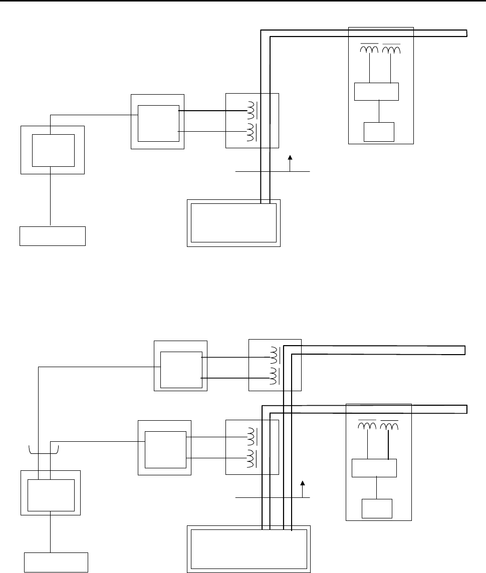
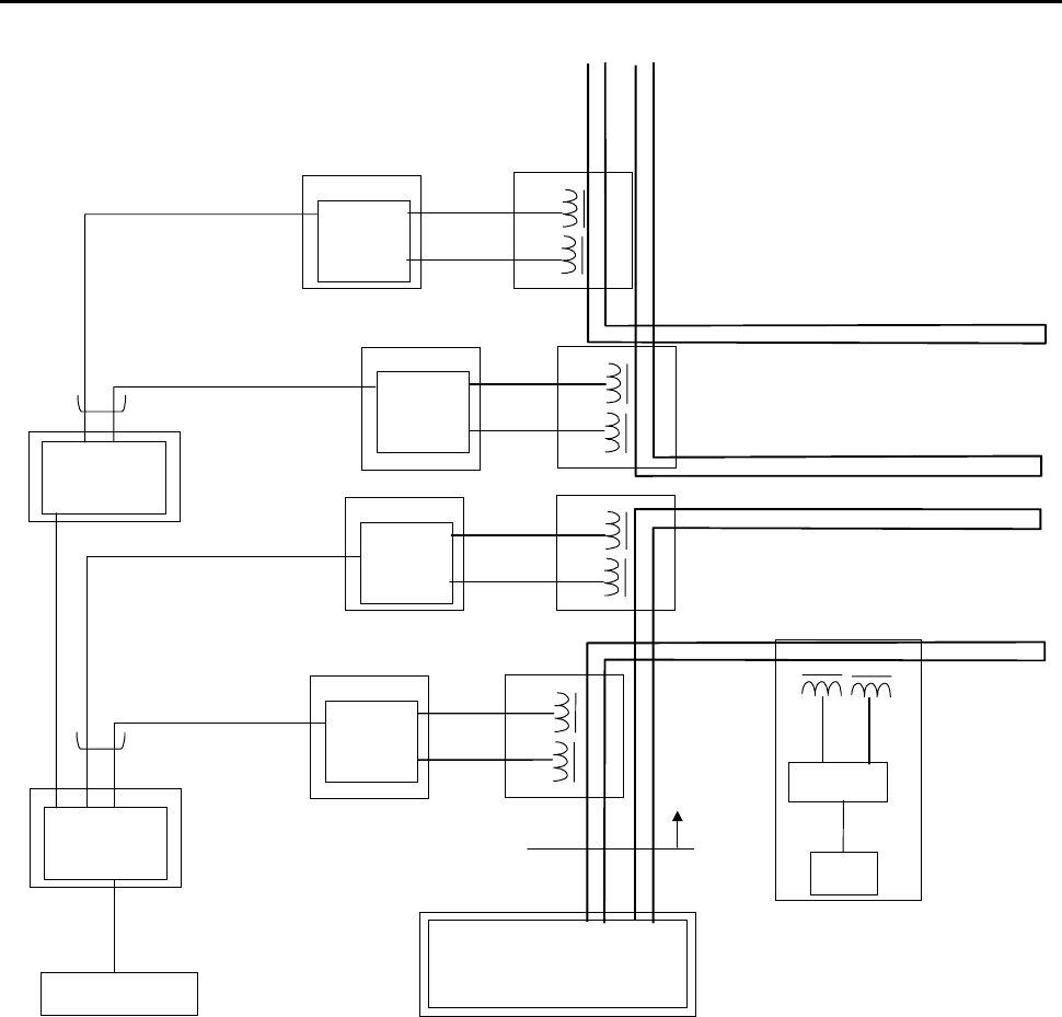
3.2. CMC configuration
Figures 1 to 3 show the basic configuration of CMC.
CMC consists of the following units.
(1)CMC-BC (Communication Modem Controller :Base Controller)
¾ Printed circuit NBV-BC
¾ DC power supply (5V)
¾ Case
(2)CMC-BM (Communication Modem Controller :Base Modem)
¾ Printed circuit BV-BM2
¾ DC power supply (24V,5V,±12V)
¾ Case
(3)CMC-TR(Communication Modem Controller :TRansformer)
¾ Communication transformer(transmission, reception)
¾ Case
FCC ID: OPO199909010003
Outline
SHINKO ELECTRIC CO.,LTD K44-2127 Rev.0 Communication unit CMC Operation Manual 7
Vehicle Controller
Power Supply Panel
CMC-BC
CMC-BCCMC-BC
CMC-BC
Power Supply Unit
Power Supply Line
(Parallel Wire)
PCB
NBV-BC
PCB
BV-BM2
TX
RX
CMCBM
CMCBMCMCBM
CMCBM CMC-TR
CMC-TRCMC-TR
CMC-TR
Digital Signal line with shield
Digital Signal line with shield
Analog Signal line with shield
Modem
CPU
TX RX
Vehicle
Track
Fig. 1 Basic configuration of CMC
Power Supply Panel
CMC-BC
CMC-BCCMC-BC
CMC-BC
Power Supply Unit
Power Supply Line
(Parallel Wire)
CMCBM
CMCBMCMCBM
CMCBM
TX
RX
CMC-TR
CMC-TRCMC-TR
CMC-TR
Digital Signal line with shield
Digital Signal line with shield
Analog Signal line with shield
Modem
CPU
TX RX
Vehicle
Track
PCB
BV-BM2
CMCBM
CMCBMCMCBM
CMCBM
TX
RX
CMC-TR
CMC-TRCMC-TR
CMC-TR
Digital Signal line with shield
Analog Signal line with shield
Output: 8-Port maximum
PCB
NBV-BC
Vehicle Controller
PCB
BV-BM2
Fig. 2 Modified CMC configuration Example 1
FCC ID: OPO199909010003
Outline
SHINKO ELECTRIC CO.,LTD K44-2127 Rev.0 Communication unit CMC Operation Manual 8
Power Supply Panel
Power Supply Unit
Power Supply Line
(Parallel Wire)
Digital Signal line with shield
Digital Signal line with shield
Modem
CPU
TX RX
Vehicle
Track
Digital Signal line with shield
Output: 8-Port maximum
CMC-BC
CMC-BCCMC-BC
CMC-BC
PCB
NBV-BC
Vehicle Controller
CMC-BM
CMC-BMCMC-BM
CMC-BM
TX
RX
CMC-TR
CMC-TRCMC-TR
CMC-TR
Analog Signal line with shield
PCB
BV-BM2
CMC-BM
CMC-BMCMC-BM
CMC-BM
TX
RX
CMC-TR
CMC-TRCMC-TR
CMC-TR
Analog Signal line with shield
PCB
BV-BM2
CMC-BM
CMC-BMCMC-BM
CMC-BM
TX
RX
CMC-TR
CMC-TRCMC-TR
CMC-TR
PCB
BV-BM2
CMCBM
CMCBMCMCBM
CMCBM
TX
RX
CMC-TR
CMC-TRCMC-TR
CMC-TR
PCB
BV-BM2
CMC-BC
CMC-BCCMC-BC
CMC-BC
PCB
NBV-BC
Output: 8-Port maximum
Digital Signal line with shield
Fig. 3 Modified CMC configuration Example 2

FCC ID: OPO199909010003
Outline
SHINKO ELECTRIC CO.,LTD K44-2127 Rev.0 Communication unit CMC Operation Manual 9
3.3. Function of each unit
3.3.1. CMC-BC (Communication Modem Controller :Base Controller)
This is an interface unit to handle the signals from/to the Vehicle controller. It also serves
as the multiplexer for several CMC-BM units.
CMC-BC can work in two different modes, master mode and slave mode. It allows the
user to use the multiple units according to the scale of the conveyance system.
The CMC-BC unit may vary in its outward form depending on the conveyance system.
However, the internal configuration is common. Figure 4 shows the block diagram of CMC-
BC.
Figure 5 shows the outward form of the CMC-BC’s main printed circuit board NBV-BC.
Figure 6 shows for example the outward form of the CMC-BC unit.
3.3.2. CMC-BM(Communication Modem Controller :Base Modem)
This is a modem unit to handle the signals from/to several vehicles.
It incorporates a driver that modulates the digital signals sent from CMC-BC to analog
signals and overlay the converted signals onto the non-conductive power line or signal line.
It also demodulates the analog signals sent from the vehicles to digital signals and
transmit them to CMC-BC.
The CMC-BM unit may vary in its outward form depending on the conveyance system.
However, the internal configuration is common. Figure 4 shows the block diagram of CMC-
BM.
Figure 7 shows the outline form of the CMC-BM’s main printed circuit board BV-BM2.
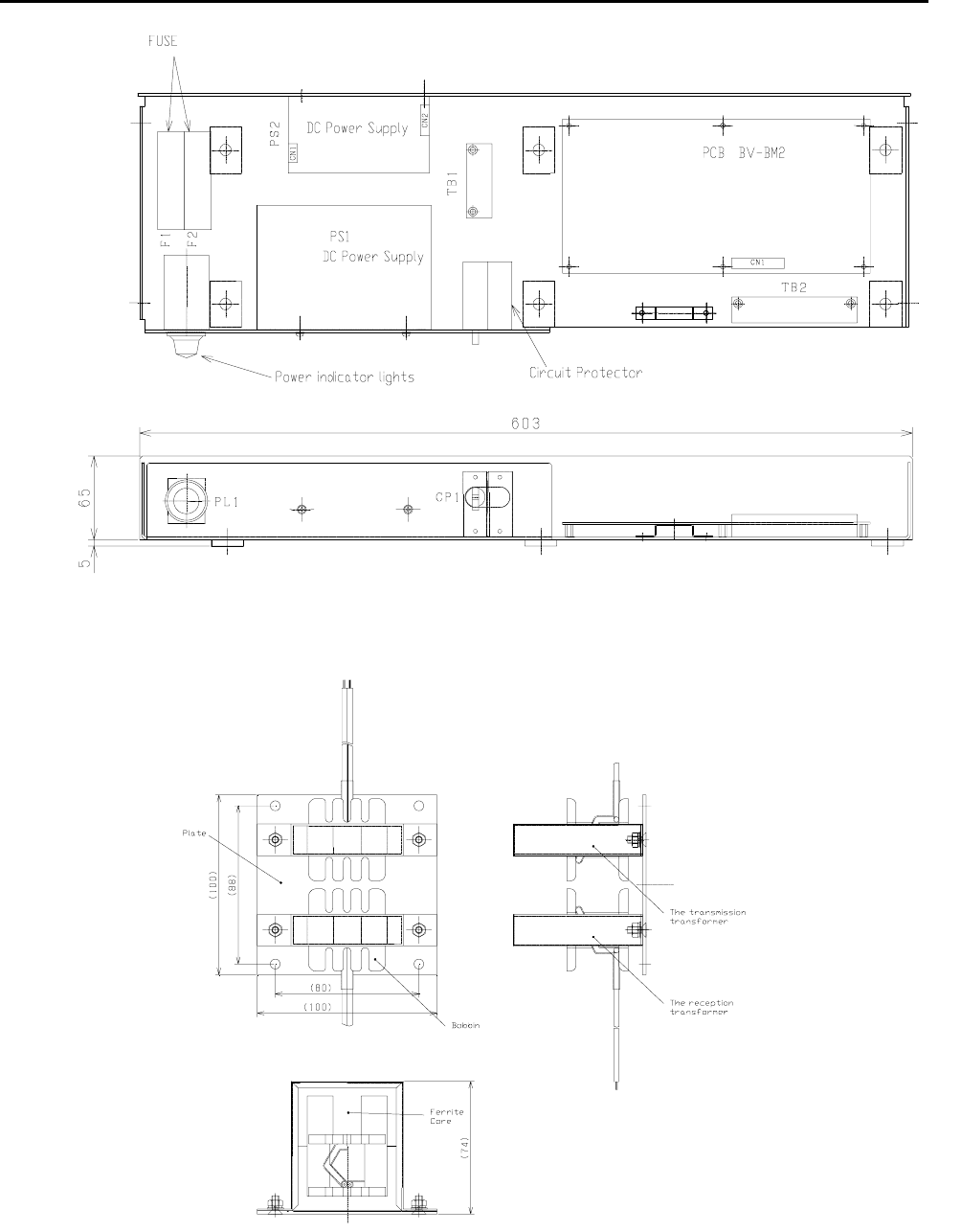
Figure 8 shows for example the outline form of the CMC-BM unit.
3.3.3. CMC-TR(Communication Modem Controller :TRansformer)
The transmission transformer overlays the signals from CMC-BM onto the non-conductive
power line or signal line.
The reception transformer receives the signals from vehicles overlaid in the non-
conductive power line or signal line.
Figure 9 shows the outer forms of the transformers.
FCC ID: OPO199909010003
Outline
SHINKO ELECTRIC CO.,LTD K44-2127 Rev.0 Communication unit CMC Operation Manual 10
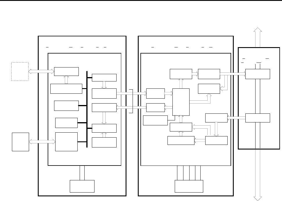
Fig. 4 The block diagram of CMC
CMC-TR
(Communication Modem
Controller-TRansfoemer)
CMC-BM
(Communication Modem Controller-Base Modem)
CMC-BC
(Communication Modem Controller-Base Controller)
BV-BM2 PCB
Demodulater
NBV-BC PCB
TX Amp
RX Amp
RX filter
Modulater
Control logic
Line driver
Line
receiver
Indicate
LED
Master/Slave
I/F
Resonance
circuit
350KHz
Line receiver
Line driver
Serial I/F
RS232C
/ RS485
Power Supply
DC5V
Power Supply
DC5,P12,N12,24V
Switch circuit
Control
logic
Block diagram
Power Line
Reset circuit
Reset circuit
X'tal OSC
24MHz
300KHz
+5V
P12V
+5V
0V
N12V
+24V
0V
HOST
Controller
From 8.66KHz power supply
To track
Squelch
Host I/F
FCC ID:OPO199909010001
Max
8Port
Line transciver
RX
transformer
TX
transformer
CMC-BC
(Slave)
FCC ID: OPO199909010003
FCC ID: OPO199909010003
Outline
SHINKO ELECTRIC CO.,LTD K44-2127 Rev.0 Communication unit CMC Operation Manual 11
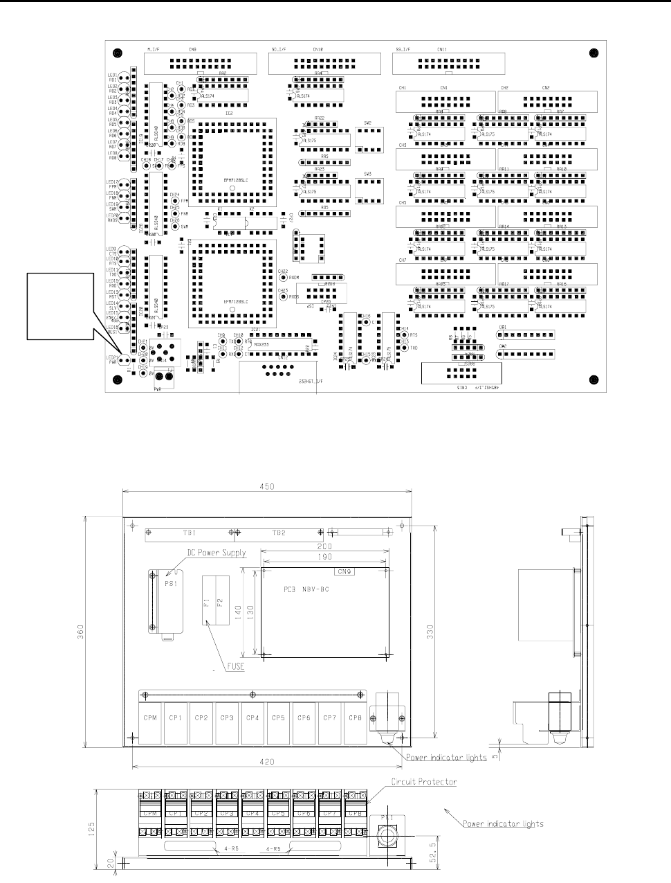
Fig. 5 Outward form of the CMC-BC’s main printed circuit board NBV-BC
Fig. 6 For example the outward form of the CMC-BC unit
The
Power
LED
FCC ID: OPO199909010003
Outline
SHINKO ELECTRIC CO.,LTD K44-2127 Rev.0 Communication unit CMC Operation Manual 12
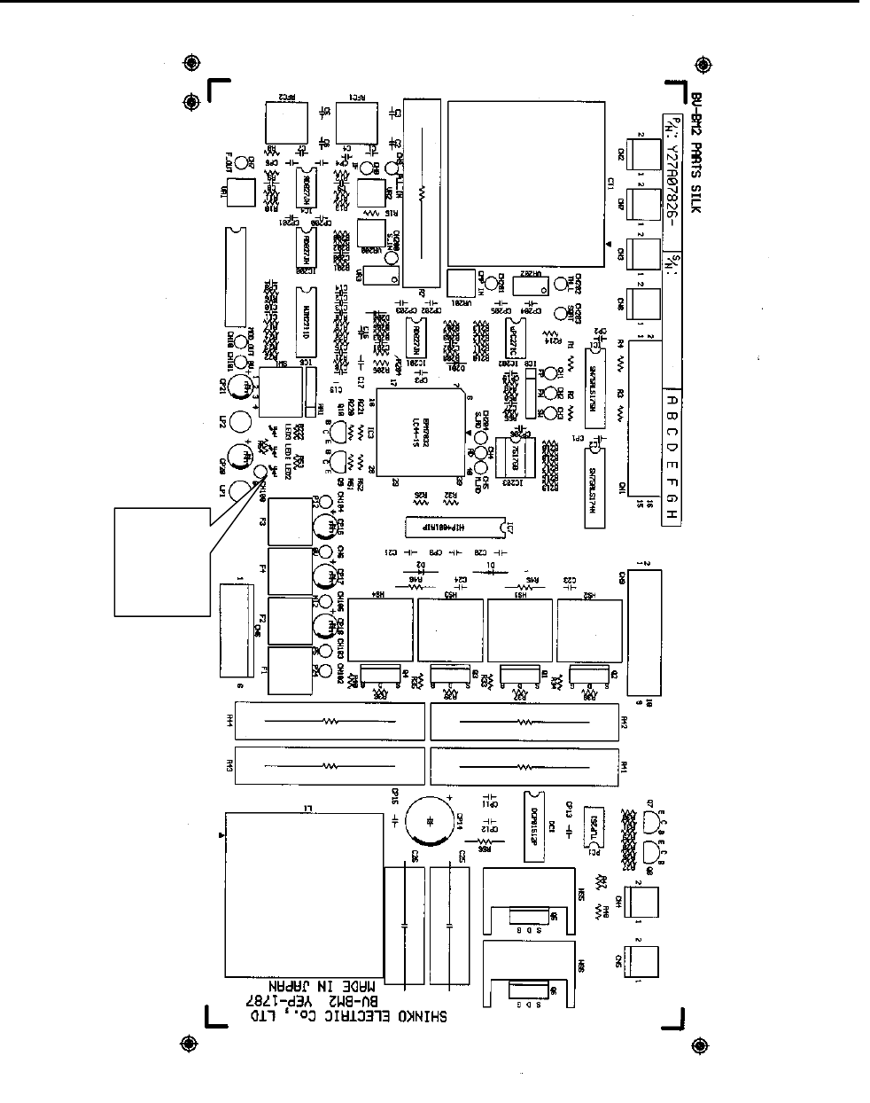
Fig. 7 The outline form of the CMC-BM’s main printed circuit board BV-BM2
The
Power
LED
FCC ID: OPO199909010003
Outline
SHINKO ELECTRIC CO.,LTD K44-2127 Rev.0 Communication unit CMC Operation Manual 13
Fig. 8 For example the outline form of the CMC-BM unit
Fig. 9 The outer forms of the transformers

FCC ID: OPO199909010003
Outline
SHINKO ELECTRIC CO.,LTD K44-2127 Rev.0 Communication unit CMC Operation Manual 14
3.4. FCC standard
The transmission assembly in the communication unit CMC meets FCC Part15 Subpart C
as the intentional radiator.
FCC ID of CMC:OPO199909010003
[Note.1]
The FCC certificate position may vary because different case materials and shapes are
adopted for different customers.
NOTICE
This equipment has been tested and found to comply with the limits for a Class A
digital device, pursuant to part 15 of the FCC Rules. These limits are designed to
provide reasonable protection against harmful interference when the equipment is
operated in a commercial environment. This equipment generates, uses, and can
radiate radio frequency energy and, if not installed and used in accordance with the
instruction manual, may cause harmful interference to radio communications.
Operation of this equipment in a residential area is likely to cause harmful interference in
which case the user will be required to correct the interference at his own expense.
FCC WARNING
Changes or modifications not expressly approved by the party responsible for
compliance could void the user's authority to operate the equipment.

FCC ID: OPO199909010003
Specification
SHINKO ELECTRIC CO.,LTD K44-2127 Rev.0 Communication unit CMC Operation Manual 15
4. Specification
Communication speed: Vehicle controller−Vehicle 19.2 kBPS (MAX 38.4 kBPS)
Communication method: FSK
4.1. CMC-BC
Unit name CMC-BC
Manufacturer SHINKO ELECTRIC CO., LTD.
Weight Approx. 10 kgf *Case materials and shape vary with the system
Size 453mm (W) x 363 mm (L) x 160 mm (H)
*Case materials and shape vary with the system
Power
consumption 10W
Input 1 200V AC 1φ or 100V AC 1φ 50/60Hz
Input 2 Vehicle controller―CMC-BC RS232C/RS485
Output 1 CMC-BC―CMC-BM RS485 8 ports max.
Output 2 CMC-BC―CMC-BC RS485 1 port
Output 3 CMC-BC―CMC-BM 200V AC 1φ or 100V AC 1φ 50/60Hz
4.2. CMC-BM
Unit name CMC-BM
Manufacturer SHINKO ELECTRIC CO., LTD.
Weight Approx.10kgf *Case materials and shape vary with the system
Size 603 mm (W) x 187.5 mm (L) x 70 mm (H)
*Case materials and shape vary with the system
Power
consumption 20W
Input 1 CMC-BC―CMC-BM 200V AC 1φ or 100V AC 1φ 50/60Hz
Input 2 CMC-BC―CMC-BM RS485
Input 3 CMC-TR―CMC-BM Analog signal 4 ports max.
Output 1 CMC-BM―CMC-TR Analog signal 2 ports max.
4.3. CMC-TR
Unit name CMC-TR
Manufacturer SHINKO ELECTRIC CO., LTD.
Weight Approx. 5 kgf *Case materials and shape vary with the system
Size 150 mm (W) x 150 mm (L) x 110 mm (H)
*Case materials and shape vary with the system
Power
consumption
MAX 1W
*When communication signal transmitted through the non-conductive
power line
Input 1 CMC-BM―CMC-TR Analog signal
Output 1 CMC-TR―CMC-BM Analog signal

FCC ID: OPO199909010003
Error Process
SHINKO ELECTRIC CO.,LTD K44-2127 Rev.0 Communication unit CMC Operation Manual 16
5. Error process
[Note.1]
Before servicing CMC-BC,CMC-BM,CMC-TR,always shut off the power supply.
[Note.2]
If the communication signals are overlaid onto the non-conductive power line, also shut off
the power source of the non-conductive power line before starting maintenance on CMC-
BM and CMC-TR.
<Communication error trouble shooting>
Vehicle Controller issues a communication error
Is Vehicle Controller sending communication signals?
Check the settings for Vehicle Controller.
Are the power indicator lights of CMC-BC and CMC-BM illuminated?
Is the power supply of 200V AC 1φ or 100V AC 1φ50/60Hz connected?
Is the input fuse burnt?
Replace the fuse.
Turn the power supply OFF. Is the input resistance of the DC power
almost 0 ohm?
Replace the DC power supply.
Is the power LED of the print circuit NBV-BC illuminated?
Is the power LED of the print circuit BV-BM2 illuminated?
Replace the print circuit board
Is the connection between CMC-BM and CMC-TR normal?
Restore connection.