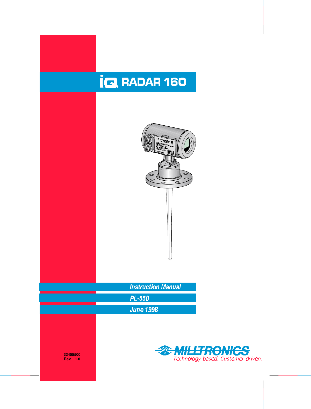
Siemens Canada Siemens Milltronics Process Instruments IQ160 Industrial Fluid Level Sensor Transmitter User Manual Users manual and operational description
Siemens Canada Ltd. - Siemens Milltronics Process Industrial Fluid Level Sensor Transmitter Users manual and operational description
Contents
- 1. Users manual and operational description
- 2. FCC Information to Users added to the manual
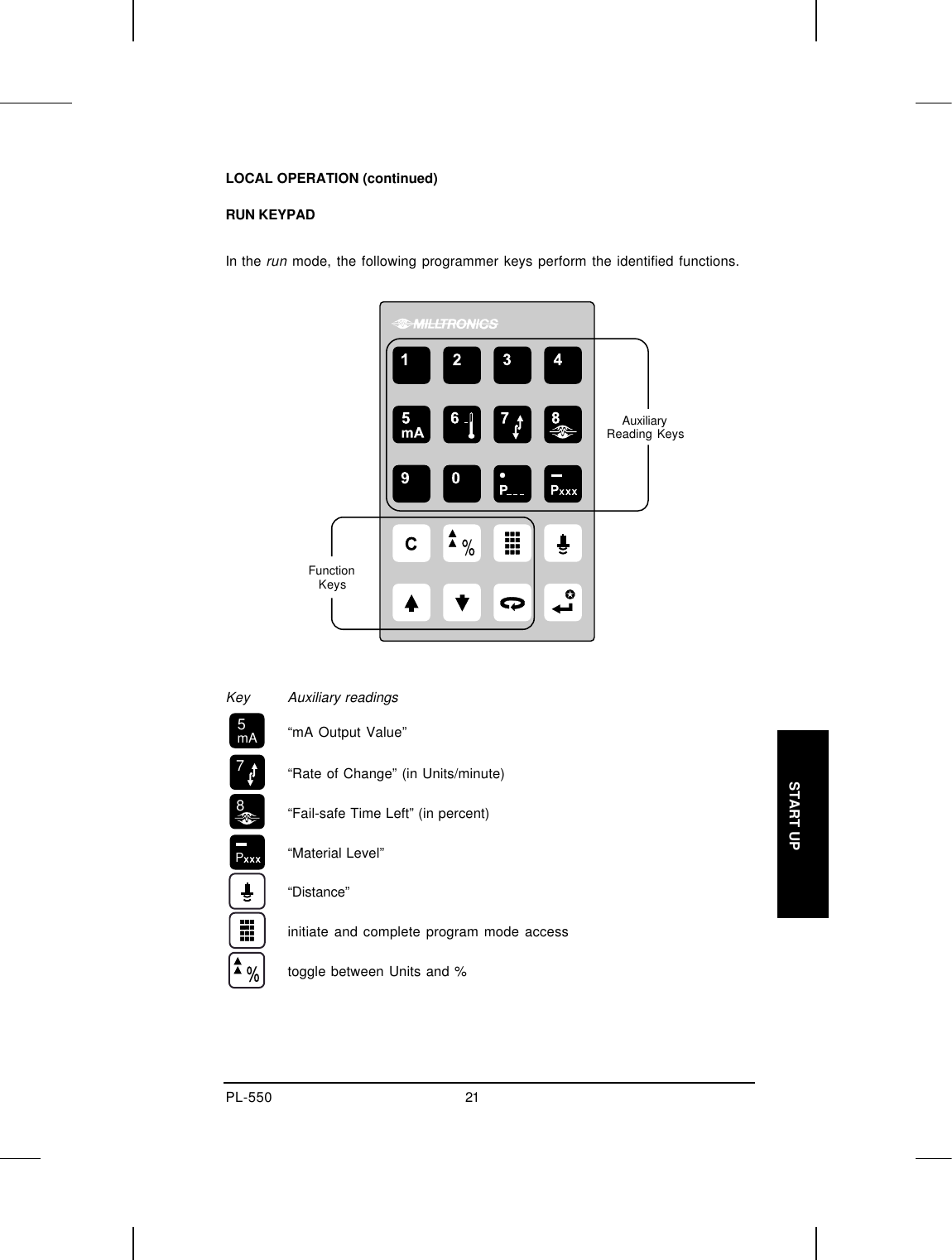
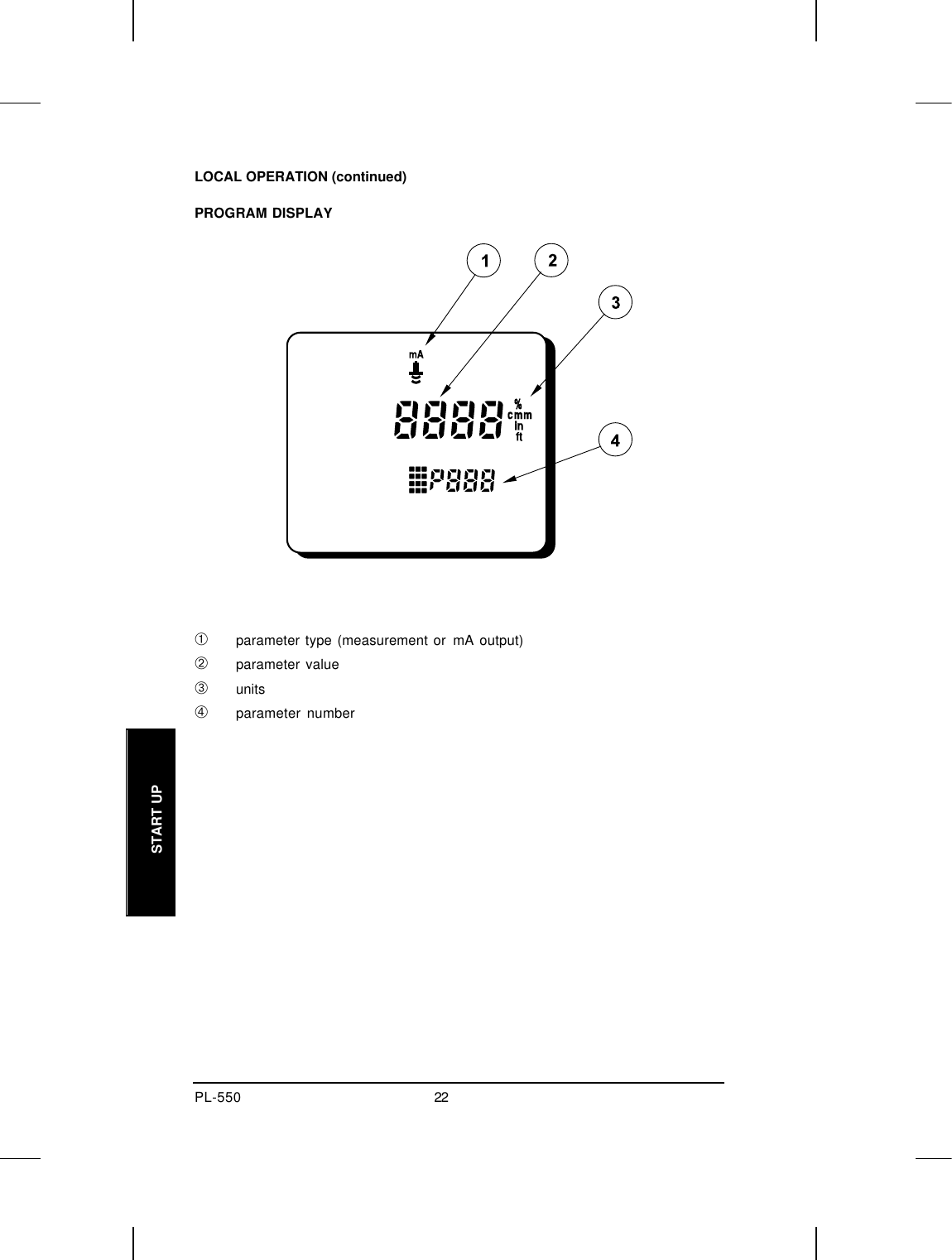
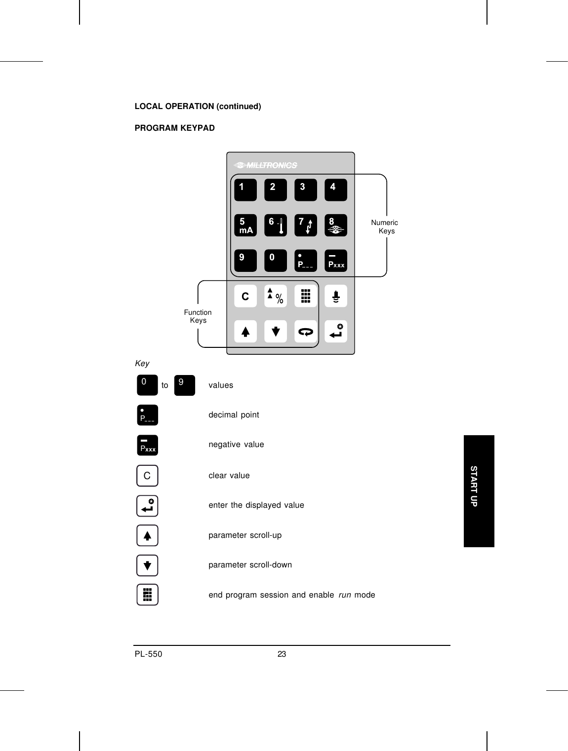
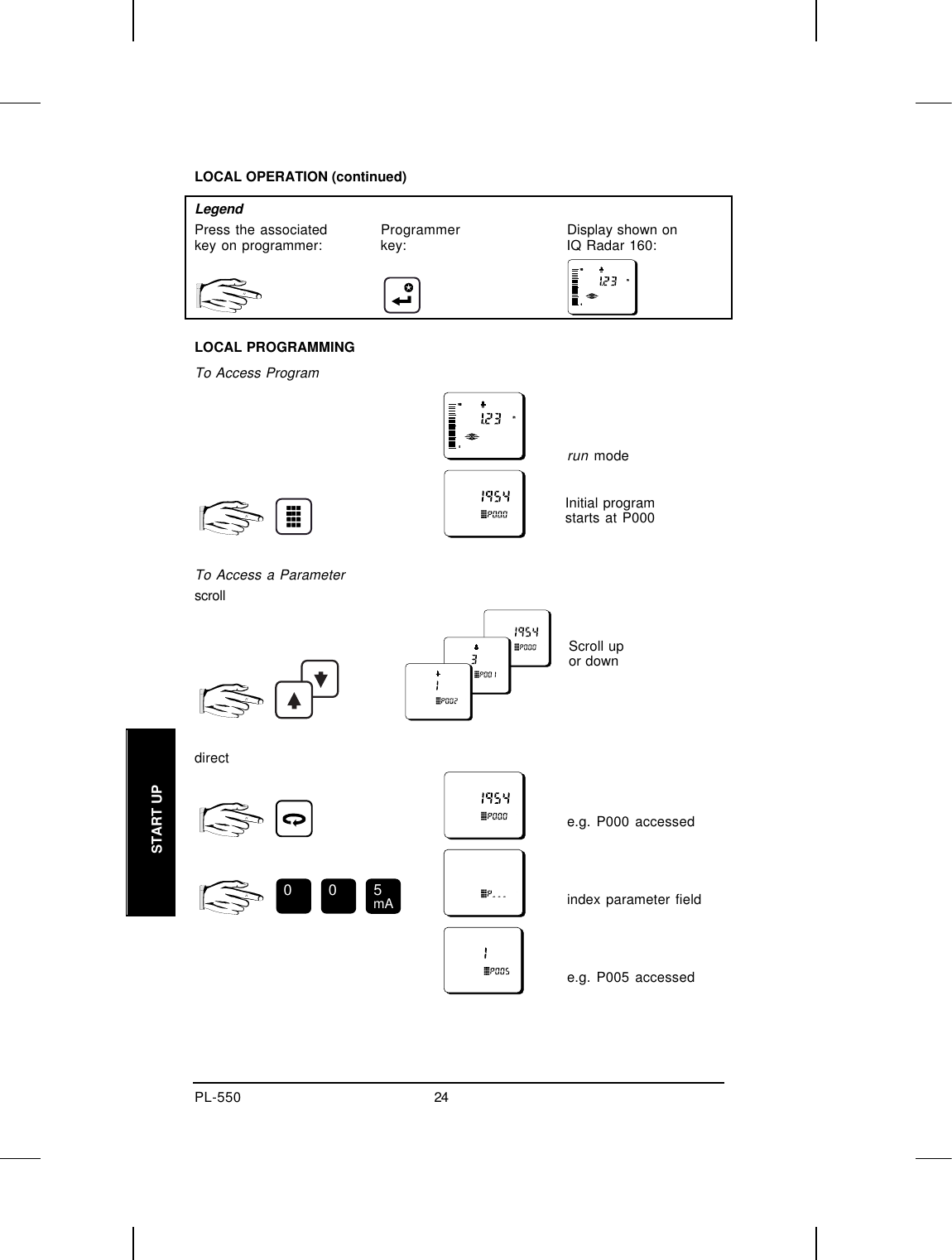
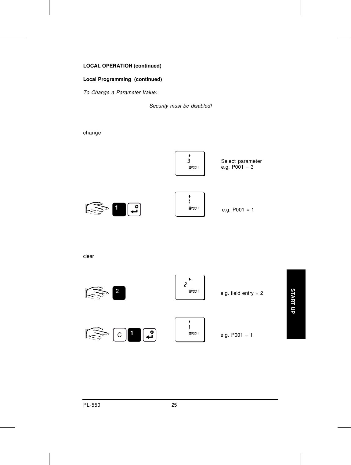
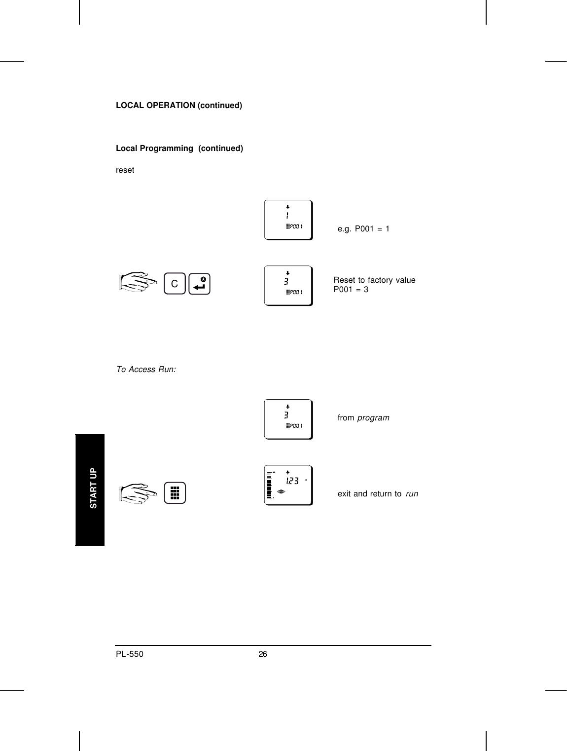
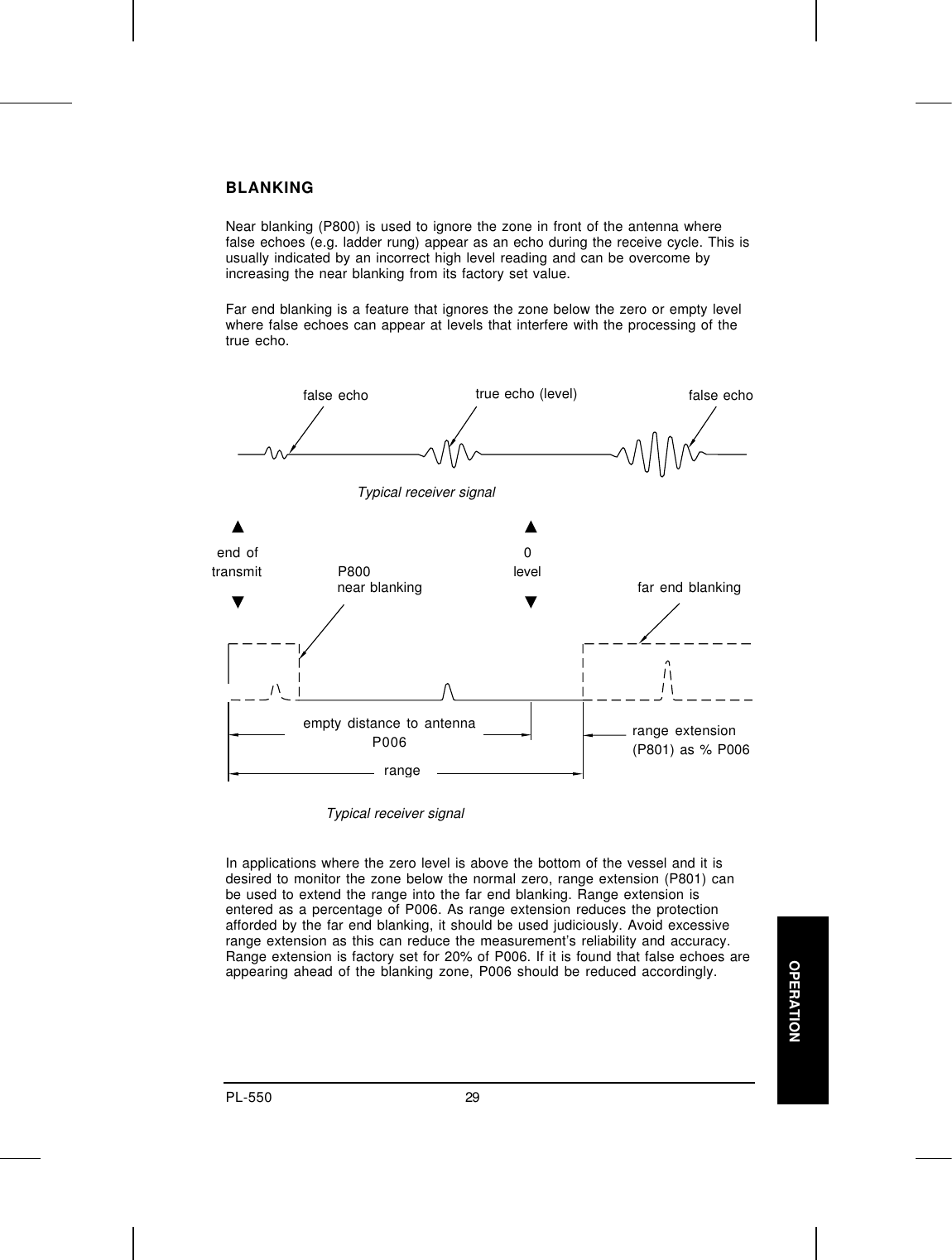
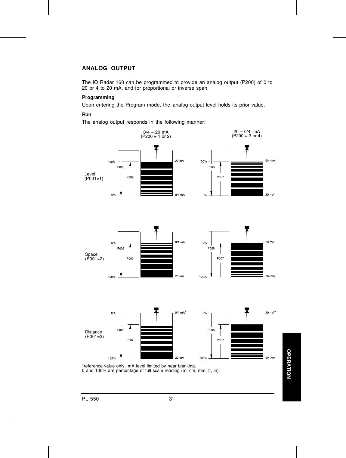
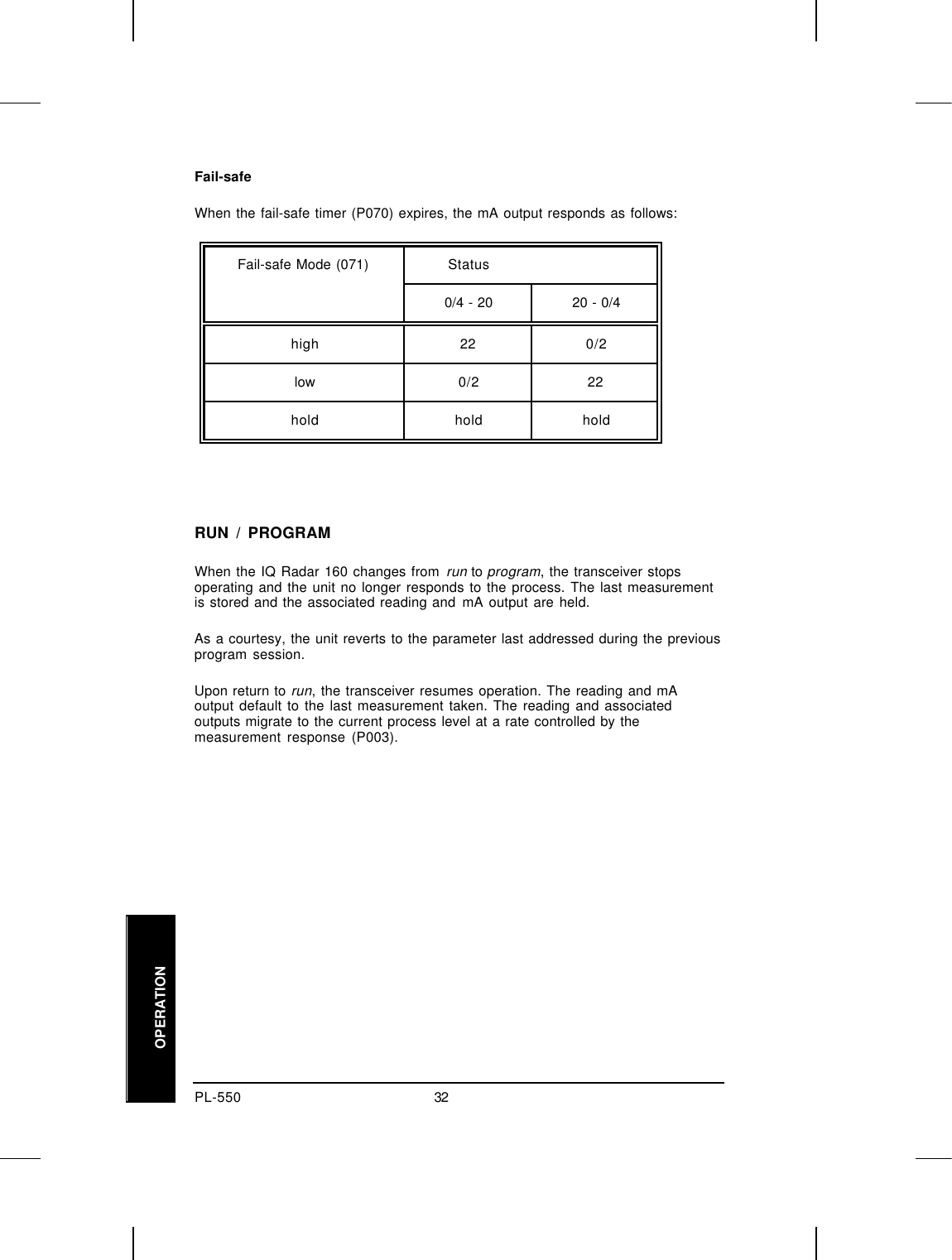
Users manual and operational description