Siemens Canada Siemens Milltronics Process Instruments IQ160 Industrial Fluid Level Sensor Transmitter User Manual Users manual and operational description
Siemens Canada Ltd. - Siemens Milltronics Process Industrial Fluid Level Sensor Transmitter Users manual and operational description
Contents
- 1. Users manual and operational description
- 2. FCC Information to Users added to the manual
Users manual and operational description
33455500
Rev1.0

hank you for purchasing Milltronics products. We endeavour to design
equipment that is simple to use and reliable in its operation, with the aim
of satisfying our customers' needs.
Milltronics has been designing and manufacturing process equipment since
1954. Our fields of expertise include ultrasonic and capacitance level
measurement, in-line weighing of dry bulk solids and motion sensing.
Milltronics is established world wide through associate offices and
representatives. Our network is continually being refined to provide our
customers with first rate sales information, engineering assistance and after
sales support.
For more details on our products and service, please contact us and we will
provide you with a listing of the offices or representatives nearest you.
T

_
PL-550 3
TABLE OF CONTENTS
GENERAL INFORMATION
About This Manual.................................................................................................5
About IQ Radar 160...............................................................................................6
SPECIFICATIONS
IQ Radar 160...........................................................................................................7
INSTALLATION
Location....................................................................................................................9
Dimensions............................................................................................................10
Mounting................................................................................................................11
Flanged.........................................................................................................11
Extension Requirements...........................................................................12
Rod Assembly .............................................................................................13
Interconnection ..................................................................................................14
Terminal Block Layout...............................................................................14
Wiring.............................................................................................................15
START UP
Overview ................................................................................................................17
Display and Keypad............................................................................................19
Local Operation....................................................................................................20
Run Display..................................................................................................20
Run Keypad.................................................................................................21
Program Display..........................................................................................22
Program Keypad.........................................................................................23
Local Programming....................................................................................24
OPERATION
Overview ................................................................................................................27
Transceiver............................................................................................................28
Blanking.................................................................................................................29
Loss of Echo.........................................................................................................30
Analog Output......................................................................................................31
Programming...............................................................................................31
Run.................................................................................................................31
Fail-safe.........................................................................................................32
Run / Program......................................................................................................32
Application Example...........................................................................................33
PARAMETER DESCRIPTION ...........................................................................................35
TROUBLESHOOTING ........................................................................................................41
MAINTENANCE ................................................................................................................... 43
APPENDICES
Alphabetical Parameter List..............................................................................45
Programming Chart ...........................................................................................46

PL-550 4

_
PL-550 5
GENERALLINFO. _
GENERAL INFORMATION
ABOUT THIS MANUAL
It is essential that this manual be referred to for proper installation and operation
of your IQ Radar 160.
Installation
gives you step-by-step direction for the installation and
interconnection of your IQ Radar 160.
Start-up
instructs you in how to operate the keypad, program the unit
and read the display.
Operation
describes the operation of the IQ Radar 160, detailing the
interoperation of the salient features.
Applications
looks at the IQ Radar 160 from a practical point of view, using
a typical application example.
Parameters
lists the parameters available to you, with a description of their
function and use. You are urged to read this section to
familiarize yourself with the parameters available to you and
get your IQ Radar 160 working to its fullest.
Troubleshooting
tabulates symptoms, causes and actions to common
installation and application problems that you might encounter.
Hopefully you will never have to read this section, but know it’s
there to help you.
Appendices
what manual would be complete without one! Ours is an
alphabetical cross-reference of the parameters and their
numbers, and a record sheet for jotting down parameter
values. Handy indeed!

PL-550 6
GENERAL INFO.
ABOUT IQ RADAR 160
The IQ Radar 160 is to be used only in the manner outlined in this manual.
IQ Radar 160 is a versatile process material level monitoring instrument. Material
level measurement is achieved using advanced pulse radar techniques. The unit
consists of an electronic component coupled to the antenna.
IQ Radar 160 Features:
✓ANSI, DIN flange or sanitary tri-clamp mounting
✓corrosion-resistant construction, aluminum enclosure with stainless steel and
Teflon® wetted parts
✓local display
✓infrared keypad and Dolphin-compatible
IQ Radar 160 Applications:
✓liquids, slurries
✓process temperatures up to 200°C
✓vacuum and pressurized vessels
IQ Radar 160 Approvals and Certificates
✓safety and radio
® Teflon is a registered trademark of Du Pont.

_
PL-550 7
SPECIFICATIONS _
SPECIFICATIONS
IQ RADAR 160
Power: 100/115/200/230 ±15% V ac*, 50/60 Hz, 15 VA
*factory set – see device nameplate
Interface:
analog output: optically-isolated 0/4-20 mA into 750 Ω max,
0.02 mA resolution
Dolphin/RS-485 link: refer to Dolphin product specification
programmer link: infrared receiver (refer to Programmer
specification below)
display (local): backlight, alphanumeric and multi-graphic liquid
crystal for readout and entry
Performance:
frequency: 5.8 GHz
accuracy: > ±0.3% of range (1 to 10 m)
range: 10 m
repeatability: 30 µW average
fail-safe: mA programmable high, low or hold
Mechanical:
enclosure (electronic):
construction: aluminum, epoxy coated
conduit: 2 x 1/2" NPT or PG 16 entry
ingress protection: Type 6 / NEMA 6 / IP-67
resonator: plated aluminum
flange: 316 stainless steel, 150 psi ANSI, DIN PN16,
3" sanitary tri-clamp
antenna:
type: dielectric rod
construction: Teflon®
weight: 6.5 kg (14.3 lb) with 2"/150 psi ANSI flange,
weight will vary with flange size and rating

PL-550 8
SPECIFICATIONS _
Environmental:
location: indoor/outdoor
altitude: 2000 m max
ambient temperature: -20 to 60° C (-4 to 140° F)
relative humidity: suitable for outdoor
(Type 6/NEMA 6/IP 67 enclosure)
installation category: II
pollution degree: 4
Process:
material dielectric: εr > 4
temperature: -40 to 200°C (-40 to 392°F)
pressure (vessel): -100 kPa to 1000 kPa
(-1 to 10 bar or -10 to 150 psi)
Programmer (remote keypad):
enclosure: general purpose
67 mm w x 100 mm h x 25 mm d
(2.6" w x 4" h x 1" d)
ambient temperature: -20 to 50° C (-5 to 122° F)
interface: proprietary infrared pulse signal
power: 9V battery (ANSI/NEDA 1604, PP3 or equivalent
weight: 150 g (0.3 lb)
Approvals (refer to device nameplate) :
safety: CSANRTL/C, CE
radio: BAPT, Transport Canada

_
PL-550 9
INSTALLATION _
INSTALLATION
LOCATION
Installation shall only be performed by qualified personnel
and in accordance with local governing regulations.
This product is susceptible to electrostatic shock.
Follow proper grounding procedures.
Do not mount in direct sunlight without the use of a sun shield.
PL-550 10
INSTALLATION _
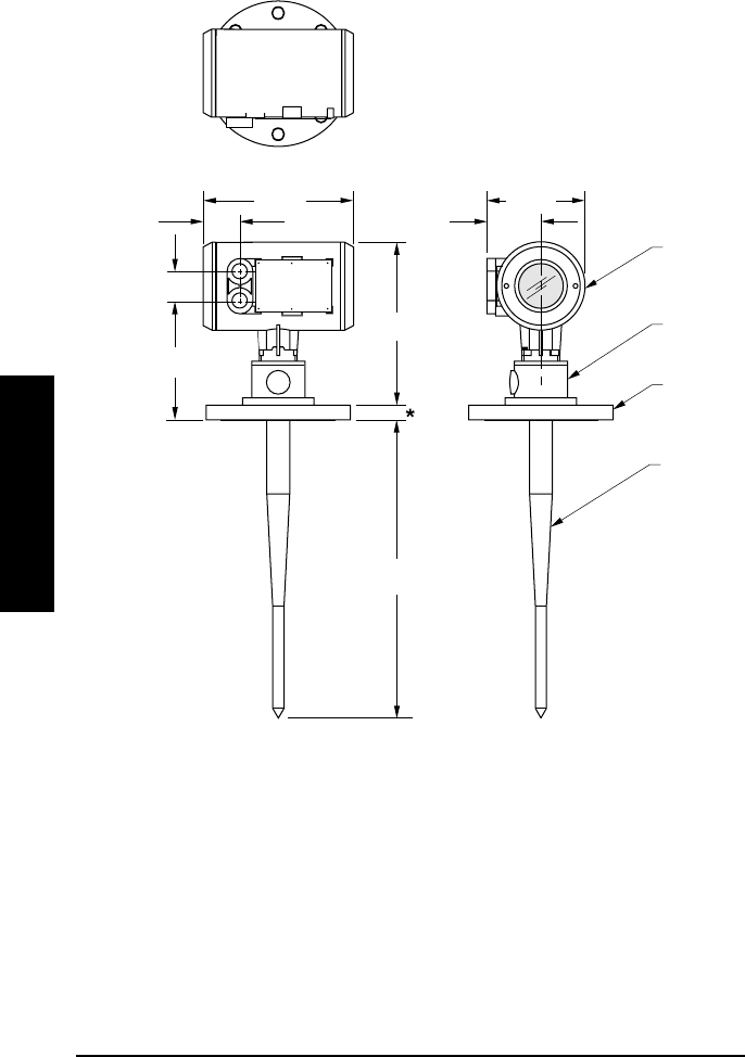
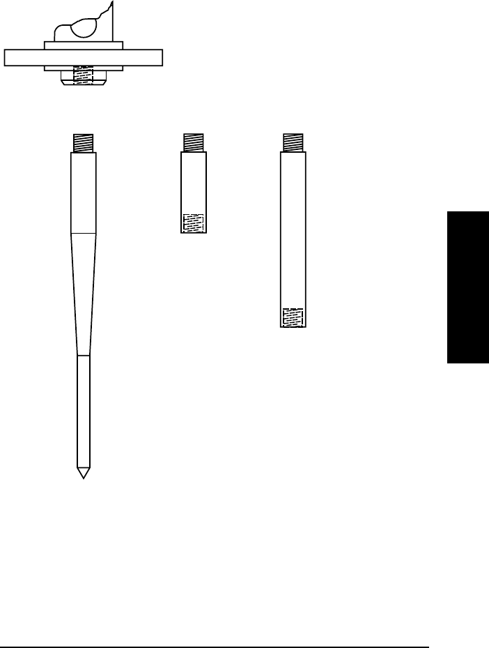
DIMENSIONS
* Flange thickness varies with size and rating. 25mm (1") nominal.
Check appropriate standard.
◊ Standard length, 50 and 100 mm (2” and 4") extensions available.
enclosure/
electronics
antenna
(rod)
antenna
(resonator)
flange or
tri-clamp
136 mm
(
5.4"
)
75 mm
(3
.
0
"
)
50mm
(
2.
0
"
)
211 mm
(8
.
3
"
)
41 mm
(
1.6"
)
183 mm
(
7.2"
)
412 mm ◊
(16.3")
245 mm
(
9.6"
)
_
PL-550 11
INSTALLATION _
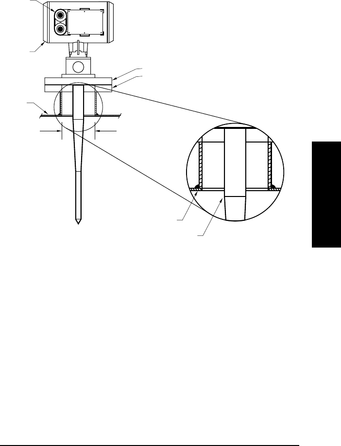
MOUNTING
FLANGED
For 2" or 3" / DIN 50 or DIN 80, the straight/taper transition of the rod should
extend past the standpipe/vessel opening. Add extensions as required.
For larger diameter standpipes, refer to Extension Requirements.
1/2" NPT
or PG 16
conduit entry
wiring
access
cover
supplied ANSI, DIN flange or sanitary tri-clamp
customer flanged standpipe to suit
tank
minimum
diameter
2" / DIN 50
rod transition
standpipe/vessel juncture
PL-550 12
INSTALLATION _
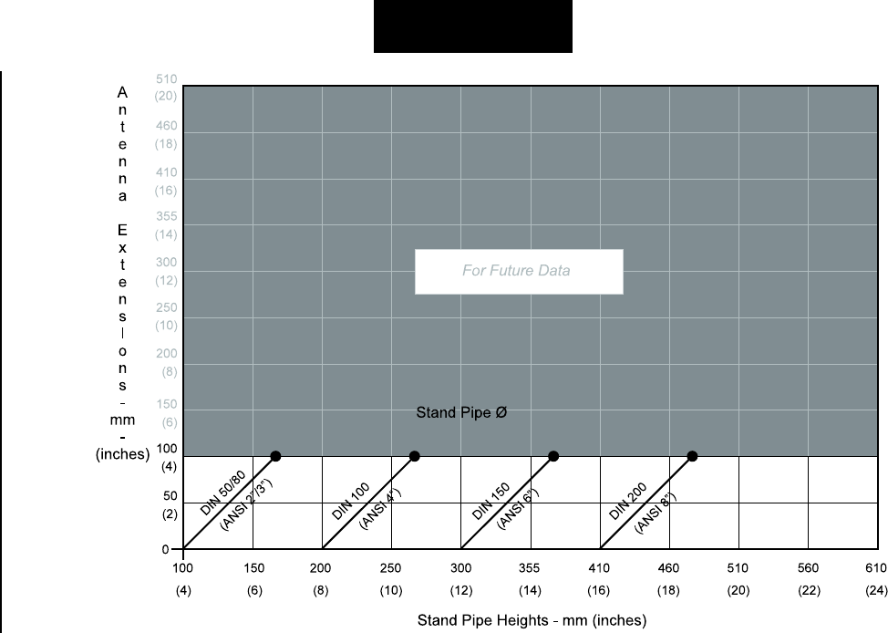
MOUNTING (continued)
EXTENSION REQUIREMENTS
_
PL-550 13
INSTALLATION _
MOUNTING (continued)
ROD ASSEMBLY
50 mm
100 mm
standard
rod
extensions
PL-550 14
INSTALLATION _
INTERCONNECTION
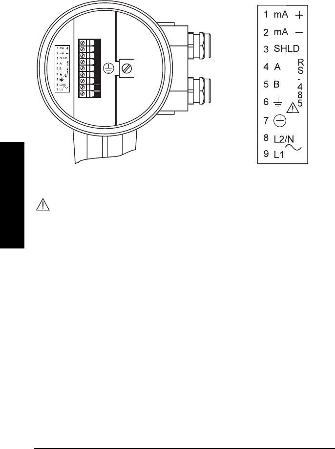
TERMINAL BLOCK LAYOUT
All field wiring must have insulation suitable for at least 250 V.
– mA wiring, 14 – 20 AWG, copper wire, shielded
– RS-485, 14 – 20 AWG, copper wire, shielded
– Line, 12 – 14 AWG, copper wire
– Recommended torque on clamping screws, 0.5 – 0.6 Nm
_
PL-550 15
INSTALLATION _
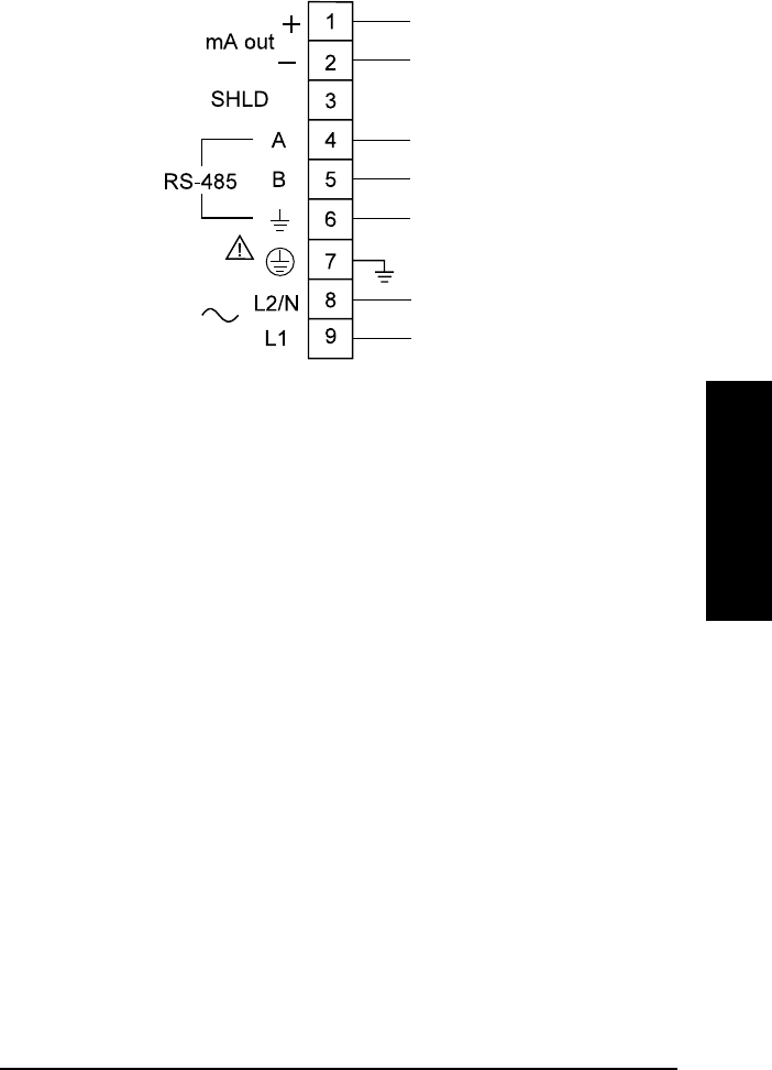
WIRING
Ground shields at one end only.
The equipment must be protected by a 15 A fuse or
circuit breaker in the building installation.
A circuit breaker or switch in the building installation, marked as the
disconnect switch, shall be in close proximity to the equipment and
within easy reach of the operator.
4-20 mA,
to instrumentation
RS-485,
to host device
V supply,
see nameplate

PL-550 16
INSTALLATION _
_
PL-550 17
START UP _
START UP
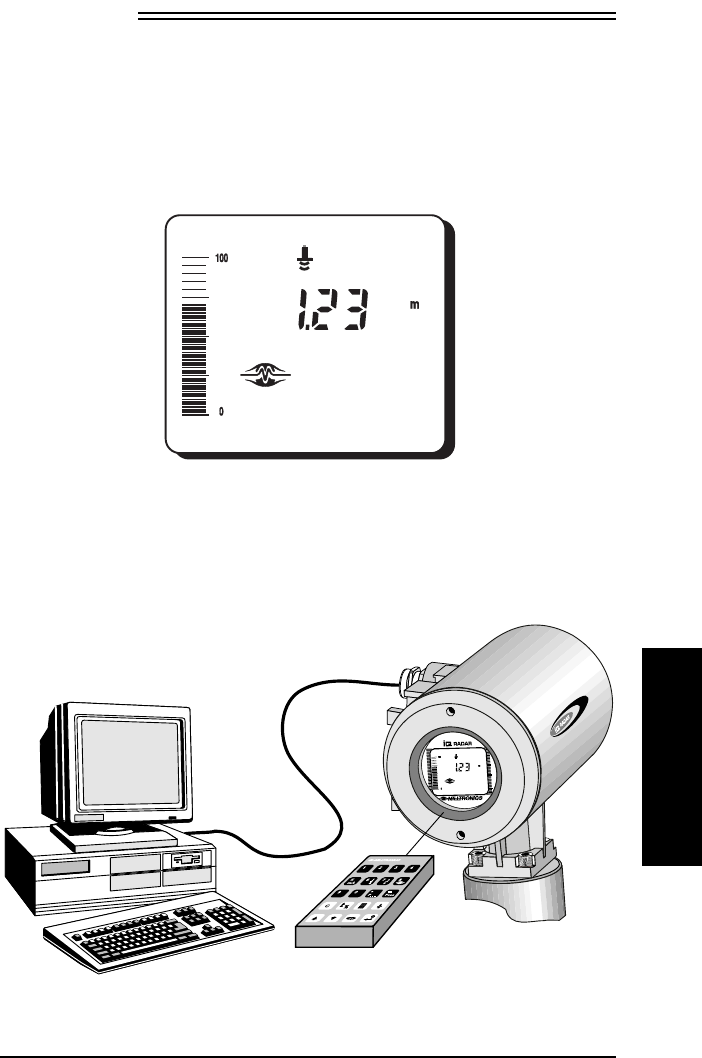
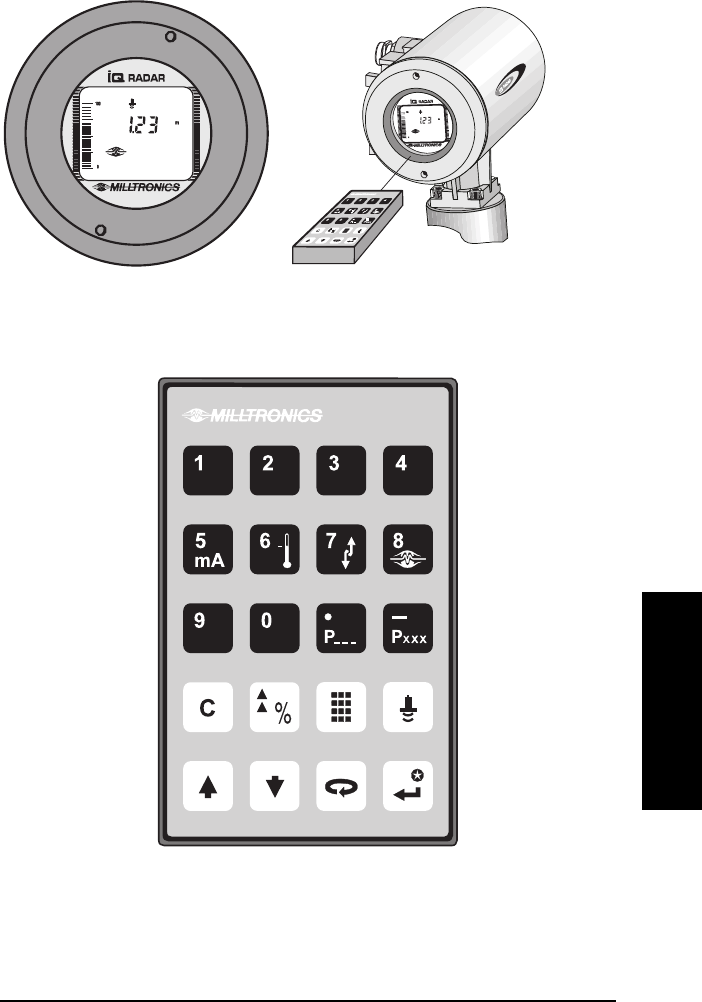
OVERVIEW
The IQ Radar 160 has two modes of operation:
run
and
program
. When the unit
is powered, after installation procedures have been completed, it is programmed
to start up in the
run
mode, to detect the distance from the antenna flange to the
target in meters.
typical display
The unit can be placed into the
program
mode at any time; to alter a number of
program parameters in order to better suit the application or user’s preferences.
Programming can be carried out locally via the hand programmer or remotely via
the optional Dolphin/RS-485 interface.
hand programmer
RS-485

PL-550 18
START UP
The first step in programming is to ensure that all parameters are at their factory
setting. The quickest way is to perform a master reset, P999.
For a Quick Start, P001 to P007 are the key parameters requiring entry.
They set: - mode of measurement
- process material
- antenna configuration
- measurement response
- units
- empty distance
- span
There are a number of other program parameters that can be changed
subsequently or during another programming session. Refer to Parameter
Description for a list of the parameters available.
When programming has been completed, the IQ Radar 160 can be put into
run
by pressing or exiting Dolphin.
_
PL-550 19
START UP _
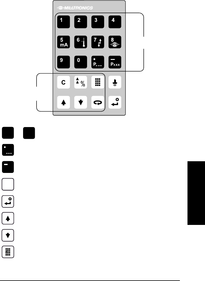
DISPLAY AND KEYPAD
PL-550 20
START UP
LOCAL OPERATION
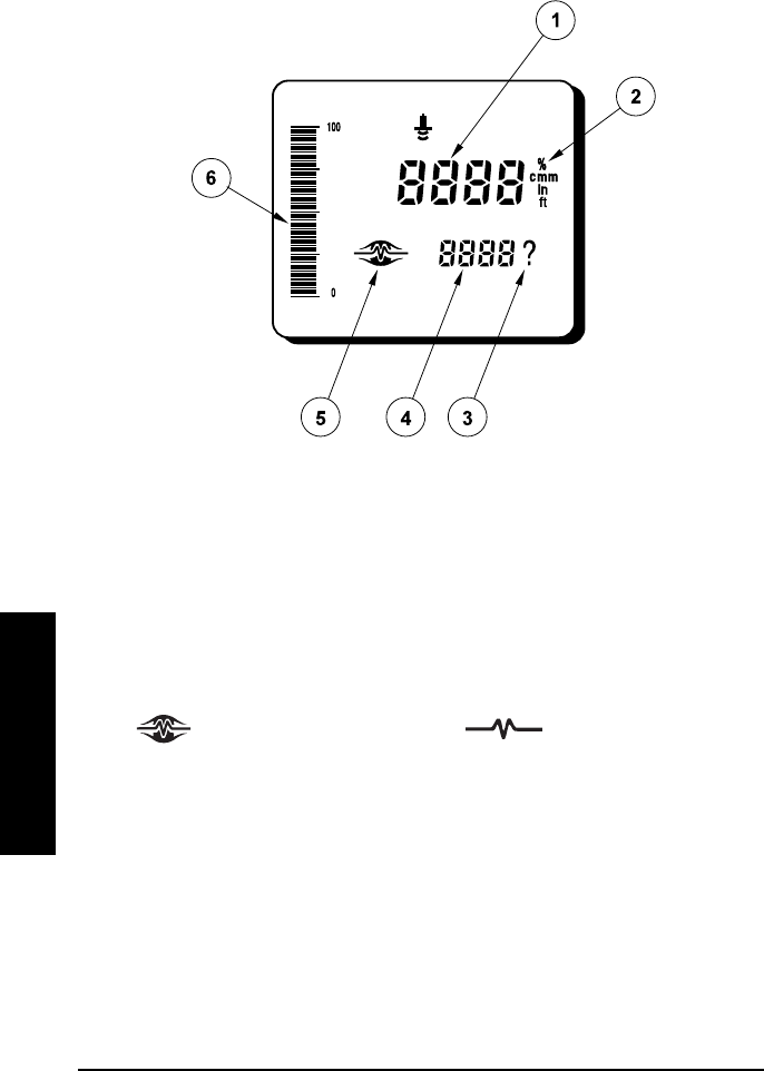
RUN DISPLAY
➀reading
➁units
➂reading questionable, appears during fail-safe operation
➃auxiliary reading
➄ = normal operation = fail-safe operation
➅bar graph representation of material level, 0 to 100% of span
_
PL-550 21
START UP _
LOCAL OPERATION (continued)
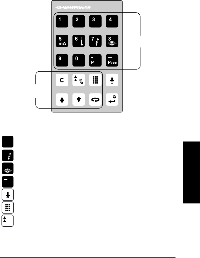
RUN KEYPAD
In the
run
mode, the following programmer keys perform the identified functions.
Key Auxiliary readings
mA
5“mA Output Value”
7“Rate of Change” (in Units/minute)
8“Fail-safe Time Left” (in percent)
PXXX“Material Level”
“Distance”
initiate and complete program mode access
%
toggle between Units and %
Auxiliary
Reading Keys
Function
Keys
PL-550 22
START UP
LOCAL OPERATION (continued)
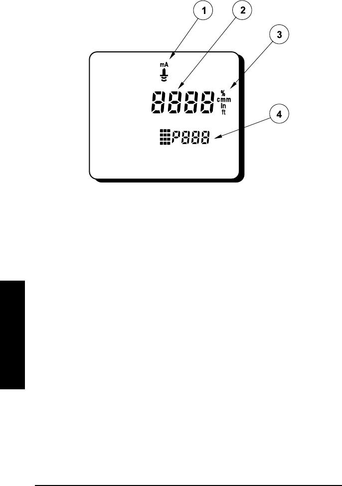
PROGRAM DISPLAY
➀parameter type (measurement or mA output)
➁parameter value
➂units
➃parameter number
_
PL-550 23
START UP _
LOCAL OPERATION (continued)
PROGRAM KEYPAD
Key
0
to 9values
Pdecimal point
PXXXnegative value
Cclear value
enter the displayed value
parameter scroll-up
parameter scroll-down
end program session and enable
run
mode
Numeric
Keys
Function
Keys
PL-550 24
START UP
LOCAL OPERATION (continued)
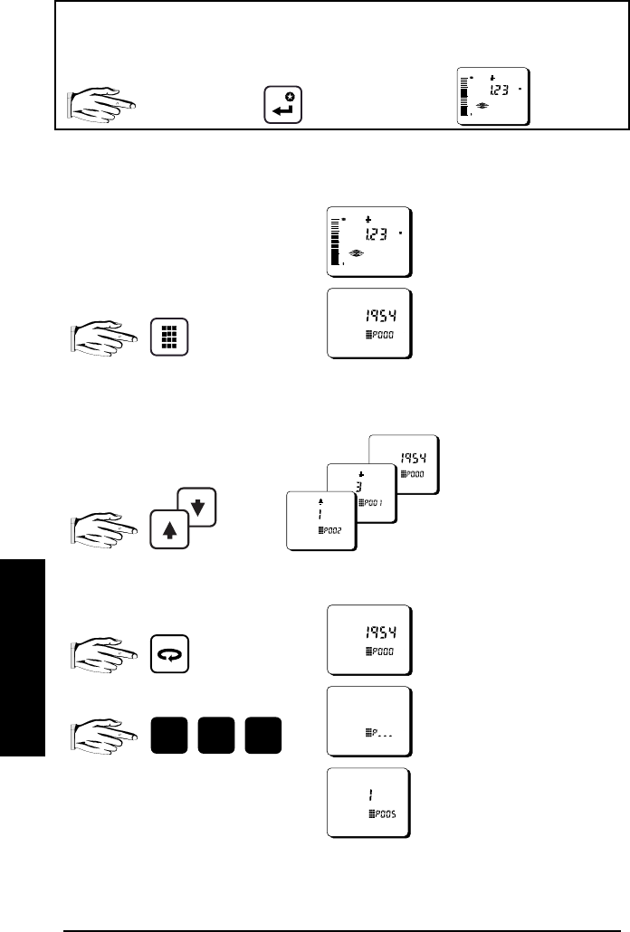
Legend
Press the associated Programmer Display shown on
key on programmer: key: IQ Radar 160:
LOCAL PROGRAMMING
To Access Program
run
mode
To Access a Parameter
scroll
direct
e.g. P000 accessed
0
0
mA
5index parameter field
e.g. P005 accessed
Initial program
starts at P000
Scroll up
or down
_
PL-550 25
START UP _
LOCAL OPERATION (continued)
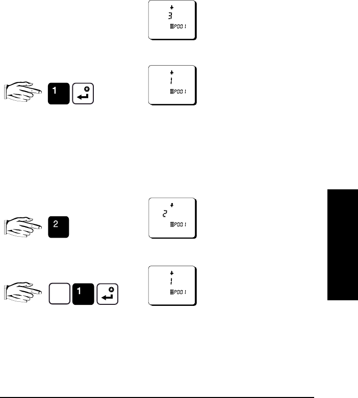
Local Programming (continued)
To Change a Parameter Value:
Security must be disabled!
change
e.g. P001 = 1
clear
e.g. field entry = 2
Ce.g. P001 = 1
Select parameter
e.g. P001 = 3
PL-550 26
START UP
LOCAL OPERATION (continued)
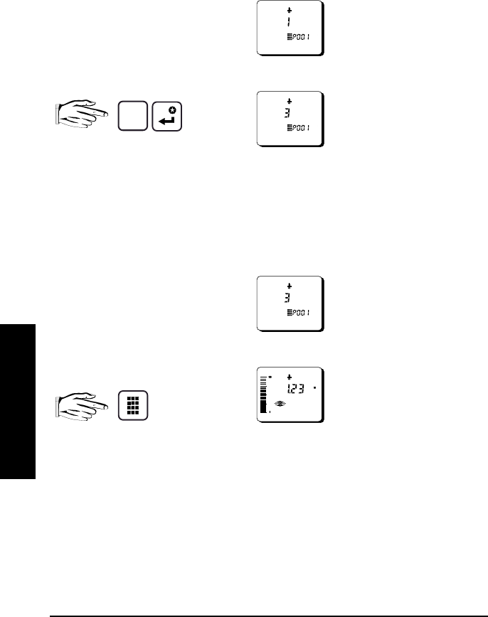
Local Programming (continued)
reset
e.g. P001 = 1
C
To Access Run:
from
program
exit and return to
run
Reset to factory value
P001 = 3

_
PL-550 27
OPERATION _
_
OPERATION
OVERVIEW
IQ Radar 160 is a process material level measuring device using advanced pulse
radar technology. The device emits a series of radar pulses and analyses the
reflection to calculate the material level.
The device consists of an enclosed electronic component, mounted to a flanged
antenna component. The electronic component generates a 5.8 GHz radar signal
which is directed to the antenna, a Teflon® dielectric rod coupled to the core of the
device’s mounting flange.
The radar signal is emitted axially from the antenna and propagates along this
axis in a defined conical beam decreasing in strength at a rate inversely
proportional to the square of the distance.
Radar reflection is based on the dielectric constant and planar property of the
materials encountered and thus radar is very suitable for still (non-agitated) liquids
and slurries. Radar is immune to temperature and atmospheric conditions and
variations in the vessel. In an ideal application, echoes from stratified vapours are
either non-existent, or minimal compared to major echoes from the process
material. Where atmospheric conditions are such that dielectric constants and
stratifications are of significance, their echoes can compete with the desired
reflection from the process material, making the application troublesome.
The series of echoes from the pulses transmitted are sensed by the antenna
during the receive period of the electronics. The echoes are stored as a profile of
the activity in the vessel. The profile is analysed and the distance of the material
surface to the radar antenna is determined. This distance is used as a basis for
display of material level and mA output.

PL-550 28
OPERATION
TRANSCEIVER
The IQ Radar 160 transceiver operates under 1 of 5 sets of preset conditions
(P003), summarized as follows:
parameter
value measurement
response echo
verification filter fail-safe
timer
1 0.1 m/min slow on on 100
2 1 m/min • on on 10
3 10 m/min • on on 1
4 100 m/min • off on 0.1
5 1000 m/min fast off off 0
When the echoes are received, the relevant echo extraction technique (P820) is
applied to determine the true material echo.
The measurement response limits the maximum rate at which the display and
analog output respond to changes in measurement. It is of concern especially
where liquid surfaces are in agitation or falls into the radar path during filling.
_
PL-550 29
OPERATION _
_
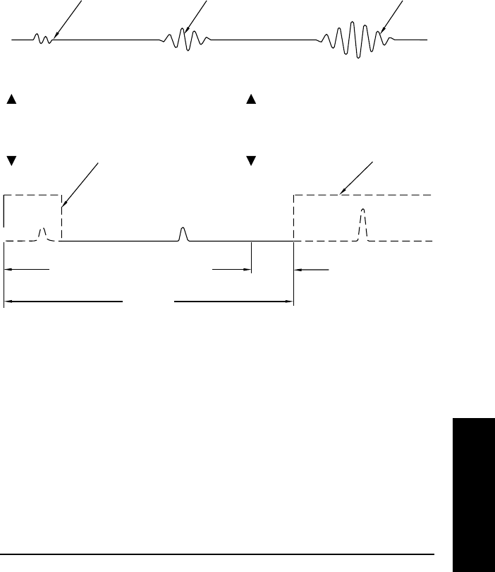
BLANKING
Near blanking (P800) is used to ignore the zone in front of the antenna where
false echoes (e.g. ladder rung) appear as an echo during the receive cycle. This is
usually indicated by an incorrect high level reading and can be overcome by
increasing the near blanking from its factory set value.
Far end blanking is a feature that ignores the zone below the zero or empty level
where false echoes can appear at levels that interfere with the processing of the
true echo.
In applications where the zero level is above the bottom of the vessel and it is
desired to monitor the zone below the normal zero, range extension (P801) can
be used to extend the range into the far end blanking. Range extension is
entered as a percentage of P006. As range extension reduces the protection
afforded by the far end blanking, it should be used judiciously. Avoid excessive
range extension as this can reduce the measurement’s reliability and accuracy.
Range extension is factory set for 20% of P006. If it is found that false echoes are
appearing ahead of the blanking zone, P006 should be reduced accordingly.
false echo false echo
true echo (level)
0
level
end of
transmit far end blanking
range extension
(P801) as % P006
empty distance to antenna
P006
Typical receiver signal
P800
near blanking
Typical receiver signal
ran
g
e

PL-550 30
OPERATION
LOSS OF ECHO
A loss of echo occurs when the IQ Radar 160 deems that the calculated
measurement is unreliable, i.e. the confidence (P805) is less than the threshold
(P804). This can be due to such circumstances as high level of electrical noise or
poor grounding. Refer to Troubleshooting. If the condition persists for a time
beyond the limit as set by the fail-safe timer (P070), the confidence icon changes
from full to partial and the reading and mA output are immediately forced to the
fail-safe default (P071).
Upon receiving a reliable echo, the loss of echo condition is aborted (icon returns
to full) and the reading and mA output return to the present level immediately.
_
PL-550 31
OPERATION _
_
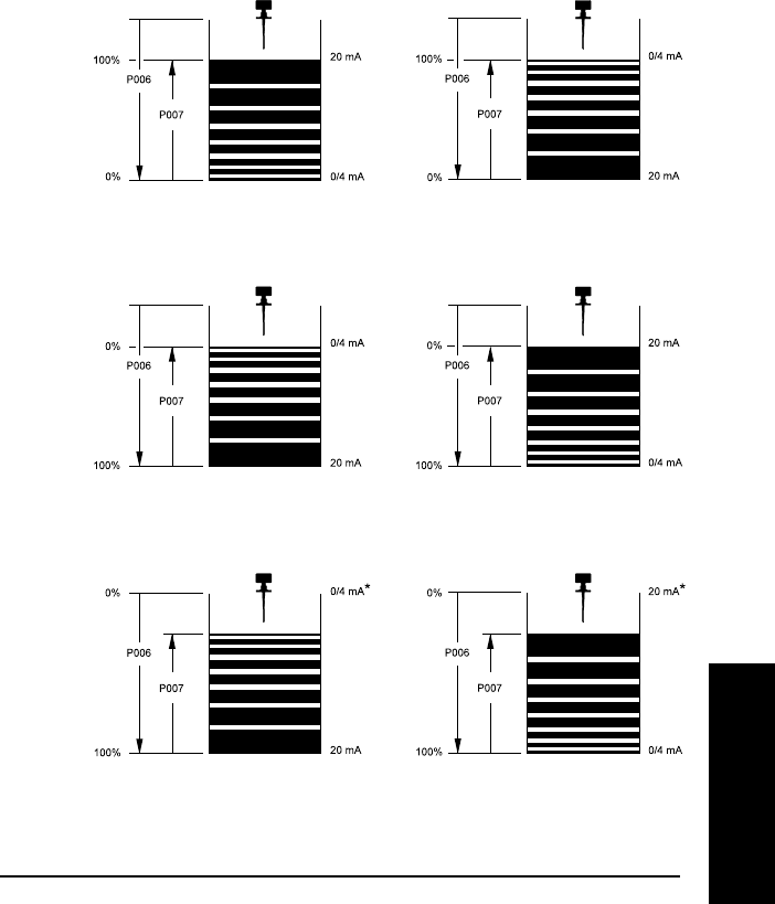
ANALOG OUTPUT
The IQ Radar 160 can be programmed to provide an analog output (P200) of 0 to
20 or 4 to 20 mA, and for proportional or inverse span.
Programming
Upon entering the Program mode, the analog output level holds its prior value.
Run
The analog output responds in the following manner:
*reference value only. mA level limited by near blanking.
0 and 100% are percentage of full scale reading (m, cm, mm, ft, in)
Level
(P001=1)
Space
(P001=2)
Distance
(P001=3)
0/4 – 20 mA
(P200 = 1 or 2) 20 – 0/4 mA
(P200 = 3 or 4)

PL-550 32
OPERATION
Fail-safe
When the fail-safe timer (P070) expires, the mA output responds as follows:
Fail-safe Mode (071) Status
0/4 - 20 20 - 0/4
high 22 0/2
low 0/2 22
hold hold hold
RUN / PROGRAM
When the IQ Radar 160 changes from
run
to
program
, the transceiver stops
operating and the unit no longer responds to the process. The last measurement
is stored and the associated reading and mA output are held.
As a courtesy, the unit reverts to the parameter last addressed during the previous
program session.
Upon return to
run
, the transceiver resumes operation. The reading and mA
output default to the last measurement taken. The reading and associated
outputs migrate to the current process level at a rate controlled by the
measurement response (P003).
_
PL-550 33
OPERATION _
_
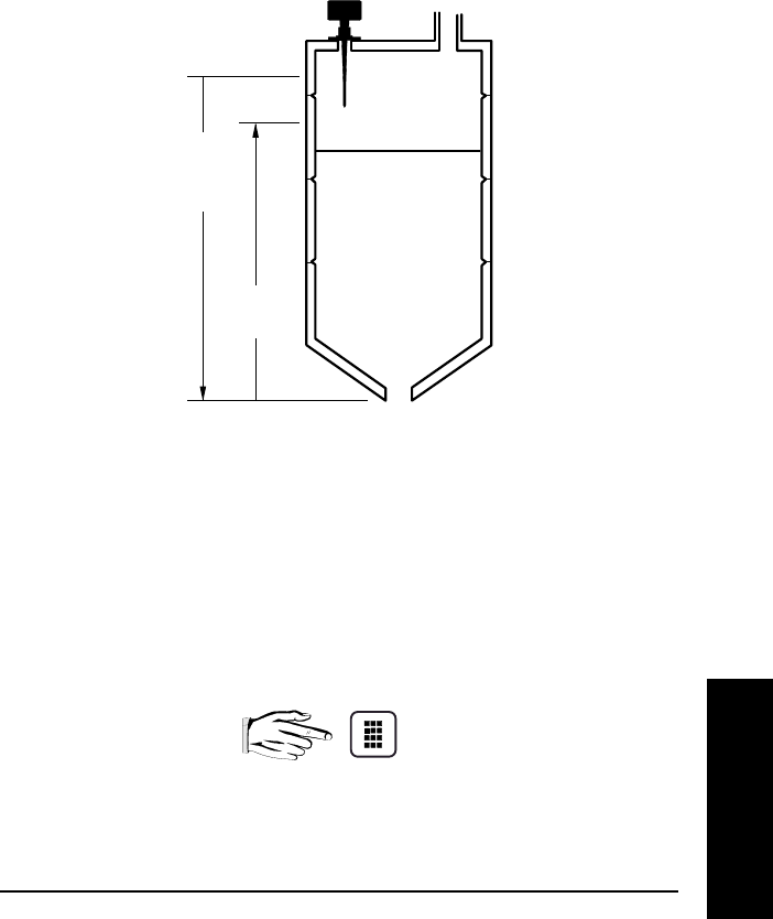
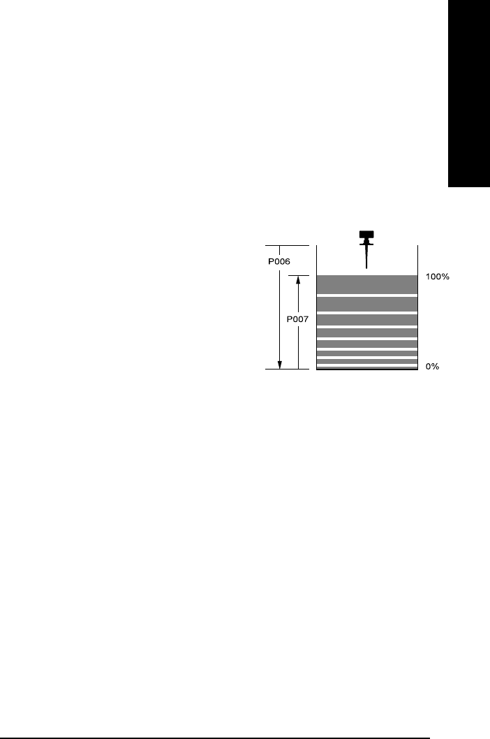
APPLICATION EXAMPLE
The minimum distance from the antenna face to the target
is limited by the near blanking, P800.
The application is to obtain a level measurement and corresponding 4-20 mA
output proportional to material levels in a chemical tank. The antenna flange is
5 m from the tank bottom. The empty level is 0 m (bottom) and the full level
(span) is 4.5 m from the bottom. The maximum rate of filling or emptying is about
1 m/min. In the event of a loss of echo, the IQ Radar 160 is to go into fail-safe low
after 2 minutes.
reset:
P999 master reset
program:
P001 enter ‘1’ mode of measurement = level
P002 enter ‘1’ material = liquid
P003 enter ‘2’ measurement response = 1m/min.
P004 enter ‘240’ antenna = dielectric rod, standard length
P005 enter ‘1’ units = metres
P006 enter ‘5’ empty distance = 5 m
P007 enter ‘4.5’ span = 4.5 m
P070 enter ‘2’ fail-safe timer = 2 min.
P071 enter ‘2’ fail-safe = low
run:
press run to start normal operation
Empty
(P006)
Span
(P007)

PL-550 34
OPERATION
_
PL-550 35
PARAMETER DESCRIPTION _
PARAMETER DESCRIPTION
P000 lock
Locks out the ability to change parameter values P001 through P999.
The program mode is still active, but restricted to viewing only. The lock
is enabled if P000 value is other than 1954.
entry: 1954 = unlocked
1954 = locked
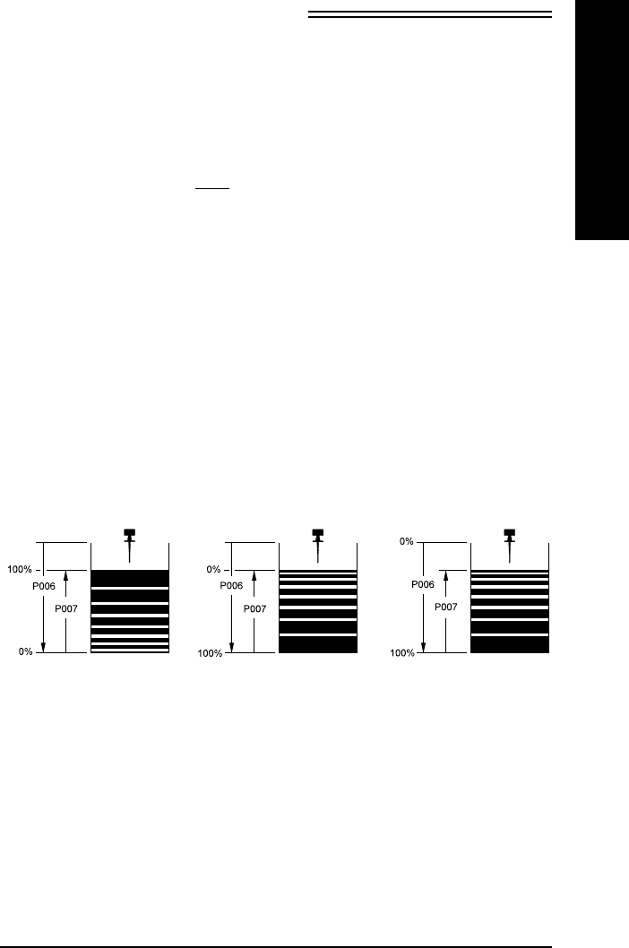
P001 operation
Determines the mode of measurement.
entry: 1 = level; material level referenced to empty
distance (P006)
2 = space; space to material level referenced
from zerospan
3 = distance; distance to target referenced
from the flange face
Level Space Distance
(P001 = 1) (P001 = 2) (P001 = 3)

PL-550 36
PARAMETER DESCRIPTION
P002 material
Optimizes measurement reliability for target type.
entry: 1 = liquids, fluids or flat surfaces
P003 measurement response
Collectively sets a number of operating parameters that determine the
maximum rate of change in target range that the reading and mA
output can keep up to.
If IQ Radar 160 cannot keep up with the rate of level change, select a
faster rate. If the reading bounces around an average value, select a
slower rate. In general, reliability is traded for speed. Noisy applications
or those with agitators tend to be more manageable at slower response
rates, as these make use of filtering, echo verification and longer fail-
safe delay.
Select P003 for a measurement response just faster than the
greater of the maximum filling or emptying rate.
echo verification: discriminates between agitator blades in motion or
spurious noise, and the target surface (true echo).
filter: discriminates between false echoes from constant
acoustical or electrical noise and the target surface.
fail-safe timer: establishes the period from the time a loss of echo
starts until the fail-safe default (P071) is effected.
The P003 preset timer value can be overridden by
P070.
entry:
measurement response echo
verification filter f-s timer
(P070)
1 = 0.1 m/min slow on on 100
2 = 1 m/min • on on 10
3 = 10 m/min • on on 1
4 = 102 m/min • off on 0.1
5 = 1020 m/min fast off off 0
_
PL-550 37
PARAMETER DESCRIPTION _
P004 antenna
Identifies antenna configuration.
entry: 240 = dielectric rod
241 = rod + 50 mm extension
242 = rod + 100 mm extension
243 = rod + 150 mm extension (50 + 100mm)
P005 units
Determines the units for programming and measurement.
entry: 1 = metres
2 = centimetres
3 = millimetres
4 = feet
5 = inches
P006 empty
Distance from flange face to empty
level or maximum target range.
P007 span
Distance from empty (P006) to
full/100% level or minimum target
range.
P070 fail-safe timer
The amount of time delay, in minutes, before going into fail-safe mode.
P071 fail-safe material level
Selects the default measurement in the event that the fail-safe timer
expires.
entry: 1 = high; maximum span value
2 = low; minimum span value
3 = hold; hold current value
P200 mA range
Enables the mA output function by selecting the range and
relationship to span.
Refer to Functional / mA output.
entry: 1 = 0 to 20 mA
2 = 4 to 20 mA
3 = 20 to 0 mA
4 = 20 to 4 mA

PL-550 38
PARAMETER DESCRIPTION
P341 run time
View the accumulated number of days the IQ Radar 160 has been
operating.
P652 offset correction
An offset value can be applied to the reading as a correction
to the measurement.
values: -999 to 9999
P800 near blanking
Sets the amount of blanking as measured from the flange face and
extending into the measurement range. Refer to Operation /
Blanking.
enter value in units of P005.
P801 range extension
Sets the amount of range extension as measured from the empty
distance (P006) and extending into the far end blanking. Refer to
Operation / Blanking.
enter as a % of P006, the distance below empty not blanked.
P804 confidence threshold
The minimum echo confidence in dB that the echo must meet in order
to prevent a loss of echo condition and the expiration of the fail-safe
timer (P070).
enter value in the range of 0 to 99.
P805 echo confidence
A measure of echo reliability.
P806 echo strength
The absolute strength of the selected echo, in dB above 1 µV rms.

_
PL-550 39
PARAMETER DESCRIPTION _
P820 algorithm
Selects the algorithm to be applied to the echo profile in order to extract
the true echo.
entry: 1 = best of first and largest
2 = first echo
3 = largest echo
P830 TVT type
Selects the TVT profile applied to the echo profile.
entry: 1 = standard
2 = flat
P900 software revision
Displays the EPROM software revision level.
P901 memory
Tests the memory. Test is initiated by scrolling to the parameter or
repeated by
display: PASS = normal
FAIL = consult Milltronics
P911 mA output value
Displays the value from the previous measurement. A test value can be
entered and the displayed value is transmitted to the output. Upon
returning to the run mode, the parameter assumes the actual mA output
level.
P920 reading measurement
Displays the reading measurement that the unit is programmed for in
run mode (P001, operation).
P921 material measurement
Displays the reading measurement as though the unit were
programmed to read level (P001 = 1).
P922 space measurement
Displays the reading measurement as though the unit were
programmed to read space (P001 = 2).
PL-550 40
PARAMETER DESCRIPTION
P923 distance measurement
Displays the reading measurement as though the unit were
programmed to read distance (P001 = 3)
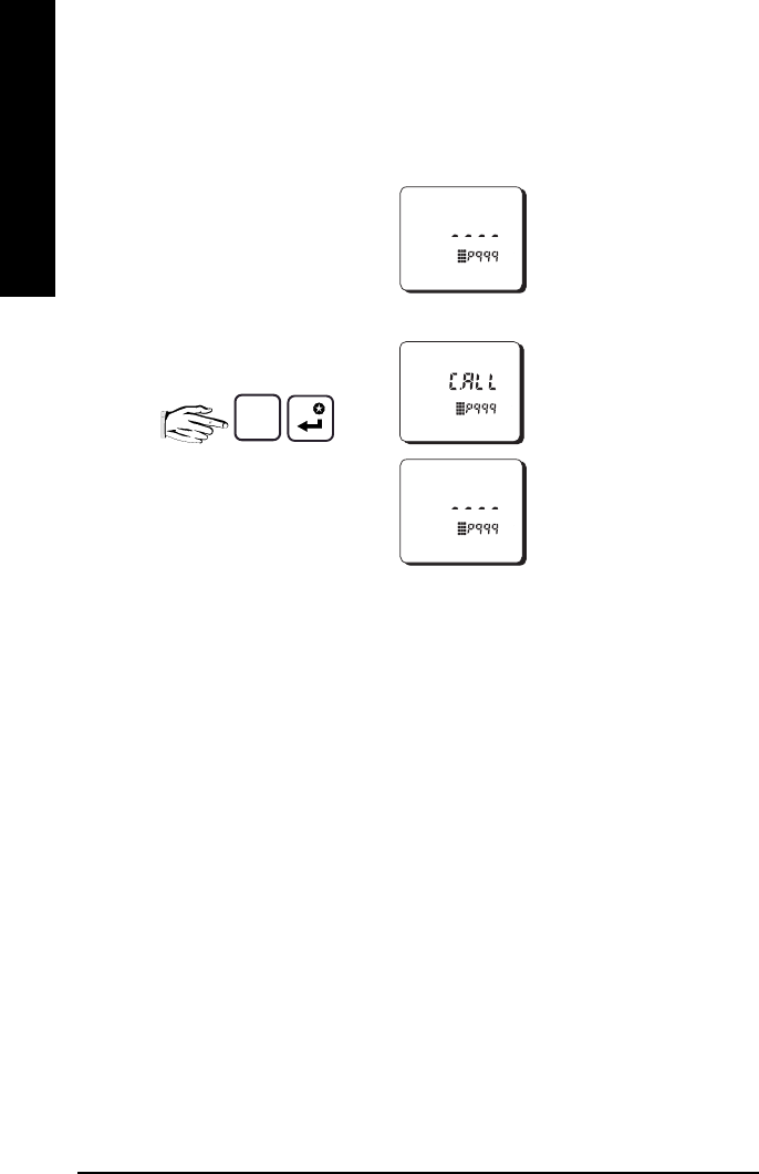
P999 master reset
Resets parameters to their factory setting
C initiate reset
reset complete

_
PL-550 41
TROUBLESHOOTING _
TROUBLESHOOTING
The following is a list of operating symptoms, their probable causes and the
actions needed to resolve them.
SYMPTOM CAUSE ACTION
display reads level or target is out of
range check specifications
check parameters
application too steamy,
under these conditions
range can be adversely
affected.
re-locate IQ Radar 160
increase fail-safe timer,
P070
material build-up on
antenna clean
re-locate IQ Radar 160
location or aiming:
-poor installation
-moved by material
or vibration
-flanging not level
-standpipe not vertical
relocate or re-aim
IQ Radar 160 for
maximum echo
confidence, P805
antenna malfunction:
-temperature too high
-physical damage
-excessive foam or skin
inspect
use foam deflector or
stilling well or relocate
Reading does not
change, but the level
does
IQ Radar 160 processing
wrong echo, i.e. vessel
wall, or structural member
re-locate IQ Radar 160
check standpipe for
internal burrs or welds
increase blanking, P800
raise short measurement
confidence threshold,
P804
*refer to associated manual
… continued

PL-550 42
TROUBLESHOOTING
SYMPTOM CAUSE ACTION
Measurement is
consistently off by a
constant amount
measurement offset correct using P652
Screen blank power error check nameplate rating
against voltage supply
check power wiring or
source
Reading erratic echo confidence weak,
liquid surface agitated,
material filling
refer to P805
decrease measurement
response P003
enable filter, echo
verification
re-locate IQ Radar 160
Reading ‘EEEE’ reading too large re-program
ie. empty distance P006
or span P007
Reading response slow P003 setting increase response if
possible
Reads correctly but
occasionally reads high
when vessel is not full
detecting close range
echo increase blanking
High level reading lower
than material level material is within near
blanking zone decrease blanking P800

_
PL-550 43
MAINTENANCE _
MAINTENANCE
The IQ Radar 160 requires no maintenance or cleaning; however, a program of
periodic checks is advised.

PL-550 44
MAINTENANCE

_
PL-550 45
APPENDICES _
APPENDICES
ALPHABETICAL PARAMETER LIST
algorithm..................................................................................................P820
antenna ..................................................................................................P004
confidence threshold ............................................................................P804
echo confidence ....................................................................................P805
echo strength..........................................................................................P806
empty........................................................................................................P006
fail-safe material level...........................................................................P071
lock............................................................................................................P000
long shot number*.................................................................................P841
mA output value ....................................................................................P911
mA range.................................................................................................P200
master reset............................................................................................P999
material ....................................................................................................P002
measurement response.......................................................................P003
memory.................................................................................................... P901
near blanking..........................................................................................P800
offset correction......................................................................................P652
operation..................................................................................................P001
range extension.....................................................................................P801
run time....................................................................................................P341
software revision ....................................................................................P900
span..........................................................................................................P007
TVT type ..................................................................................................P830
units ..........................................................................................................P005
* accessible in Dolphin only.

PL-550 46
APPENDICES
PROGRAMMING CHART
PARAMETER
#NAME VALUE
P001 Operation
P002 Material
P003 Measurement Response
P004 Antenna
P005 Units
P006 Empty
P007 Span
P070 Fail-Safe Timer
P071 Fail-Safe Material Level
P200 mA Range
P652 Offset Correction
P800 Near Blanking
P801 Range Extension
P804 Confidence Threshold
P820 Algorithm
P830 TVT Type
P841 Long-Shot Number