Siemens Canada Siemens Milltronics Process Instruments LR200 Radar Level Gauge User Manual LR 200QS EN
Siemens Canada Ltd. - Siemens Milltronics Process Instruments Radar Level Gauge LR 200QS EN
Contents
- 1. users manual
- 2. manual FCC warning draft
users manual
7ML19985QL81 SITRANS LR 200 – QUICK START MANUAL Page EN-1
mmmmm
English
SITRANS LR 200 Quick Start Manual
This manual outlines the essential features and functions of the SITRANS LR 200. We strongly
advise you to acquire the detailed version of the manual so you can use your device to its fullest
potential. The complete manual is available on our Web site: www.siemens-milltronics.com.
The printed manual is available from your local Siemens Milltronics representative.
Questions about the contents of this manual can be directed to:
Siemens Milltronics Process Instruments Inc.
1954 Technology Drive, P.O. Box 4225
Peterborough, Ontario, Canada, K9J 7B1
Email: techpubs@siemens-milltronics.com
MILLTRONICS is a registered trademark of Siemens Milltronics Process Instruments Inc.
Safety Guidelines
Warning notices must be observed to ensure personal safety as well as that of others, and to
protect the product and the connected equipment. These warning notices are accompanied by
a clarification of the level of caution to be observed.
Copyright Siemens Milltronics
Process Instruments Inc. 2003.
All Rights Reserved Disclaimer of Liability
We encourage users to purchase
authorized bound manuals, or to view
electronic versions as designed and
authored by Siemens Milltronics Process
Instruments Inc. Siemens Milltronics
Process Instruments Inc. will not be
responsible for the contents of partial or
whole reproductions of either bound or
electronic versions.
While we have verified the contents of this manual
for agreement with the instrumentation described,
variations remain possible. Thus we cannot
guarantee full agreement. The contents of this
manual are regularly reviewed and corrections are
included in subsequent editions. We welcome all
suggestions for improvement.
Technical data subject to change.
WARNING: relates to a caution symbol on the product, and means that
failure to observe the necessary precautions can result in death, serious
injury, and/or considerable material damage.
WARNING: means that failure to observe the necessary precautions can
result in death, serious injury, and/or considerable material damage.
CAUTION: means that failure to observe the necessary precautions can result
in considerable material damage.
Note: means important information about the product or that part of the operating manual.
LR-200QS-EN.fm Page 1 Wednesday, March 12, 2003 3:51 PM
Page EN-2 SITRANS LR 200 – QUICK START MANUAL 7ML19985QL81
mmmmm
English
SITRANS LR 200
SITRANS LR 200 is to be used only in the manner outlined in this manual, otherwise protection
provided by the equipment may be impaired.
SITRANS LR 200 is a 2-wire loop-powered, continuous level-measuring instrument that utilizes
advanced pulse radar technology at 5.8 GHz (6.3 GHz in the USA). The instrument consists of an
electronic component coupled to the antenna and process connection.
Specifications
For a complete listing, see the SITRANS LR 200 Instruction Manual. For Approvals information,
please refer to the process device tag.
Ambient/Operating Temperature
Power
• Maximum 30 Vdc • 4 to 20 mA
WARNING: Changes or modifications not expressly approved by Siemens
Milltronics could void the user’s authority to operate the equipment.
Note: This equipment has been tested and found to comply with the limits for a Class A
digital device, pursuant to Part 15 of the FCC Rules. These limits are designed to provide
reasonable protection against harmful interference when the equipment is operated in a
commercial environment. This equipment generates, uses, and can radiate radio frequency
energy and, if not installed and used in accordance with the instruction manual, may cause
harmful interference to radio communications. Operation of this equipment in a residential
area is likely to cause harmful interference in which case the user will be required to correct
the interference at his own expense
Note: Process temperature and pressure capabilities are dependent upon information
on the process device tag. The reference drawing listed on the tag can be downloaded
from the Siemens Milltronics Web site at www.siemens-milltronics.com
Nominal 24 Vdc with 550 Ohm: For other configurations see the full manual
process temperature
–40 oC to 80 oC (–40 oF to 176 oF)
ambient temperature
(surrounding enclosure volume)
–40 oC to 80 oC (–40 oF to 176 oF) process device
tag
LR-200QS-EN.fm Page 2 Wednesday, March 12, 2003 3:51 PM
7ML19985QL81 SITRANS LR 200 – QUICK START MANUAL Page EN-3
mmmmm
English
Approvals
• Europe:
1. General Purpose
2. Zone 0, Intrinsically safe, ia connection, IIC, T-; ATEX II 1 G
•Americas:
1. General Purpose
2. Intrinsically Safe: Class I, Div. 1, Groups A, B, C, D (barrier required)
AEx ia IIC T-
Installation
Mounting location
Recommendations
• Easy access for viewing the display and programming via the hand programmer.
• An environment suitable to the housing rating and materials of construction.
Precautions:
• Avoid proximity to high voltage or current wiring, high voltage or current contacts,
and to variable frequency motor speed controllers.
• Avoid interference to the emission cone from obstructions or from the fill path.
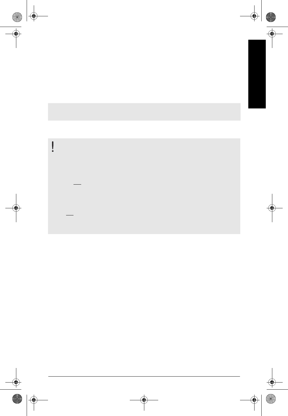
Note: The use of approved watertight conduit hubs/glands is required for Type 4X /
NEMA 4X / IP67 (outdoor) applications.
WARNINGS:
• This product can only function properly and safely if it is correctly
transported, stored, installed, set up, operated, and maintained.
• This product is designated as a Pressure Accessory per Directive 97 / 23 / EC,
and is not intended for use as a safety device.
• The user is responsible for the selection of bolting and gasket materials
which will fall within the limits of the flange and its intended use, and
which are suitable for the service conditions.
•Do not
attempt to loosen, remove, or disassemble process connection or
instrument housing while vessel contents are under pressure.
• Improper installation may result in loss of process pressure.
LR-200QS-EN.fm Page 3 Wednesday, March 12, 2003 3:51 PM
Page EN-4 SITRANS LR 200 – QUICK START MANUAL 7ML19985QL81
mmmmm
English
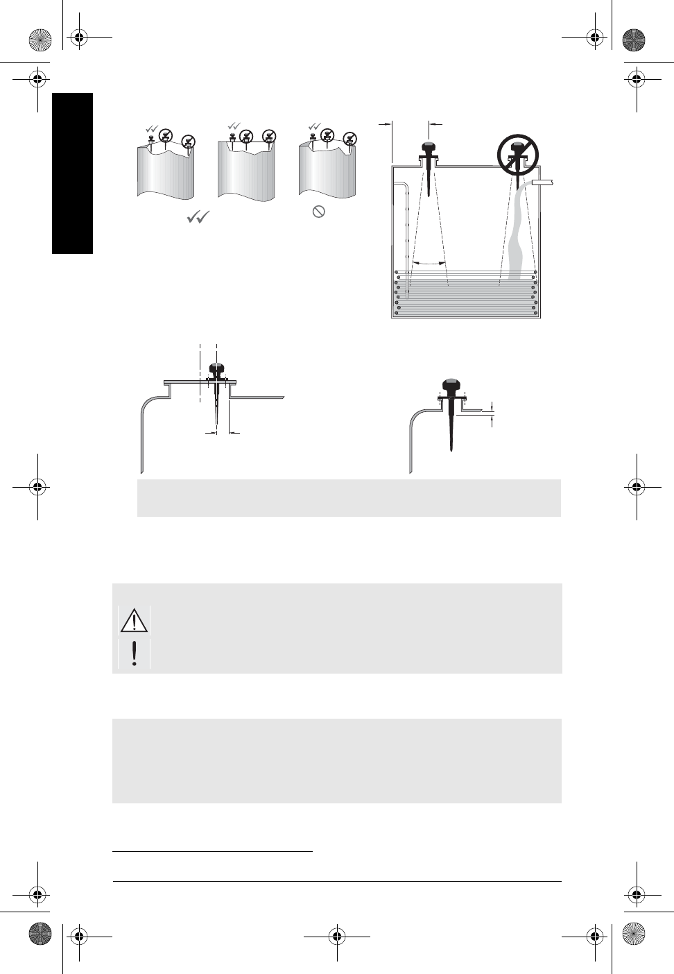
• Avoid central locations on vessels
s.
Wiring
Power
Connecting SITRANS LR 2001
• Use the 100 mm (4") shield on nozzles that are 100 mm (4") in length, or shorter.
• Use the 250 mm (10") shield on nozzles that are 250 mm (10") in length, or shorter.
WARNINGS:
dc terminals shall be supplied from an SELV source in accordance with
IEC-1010-1 Annex H.
All field wiring must have insulation suitable for rated input voltages.
Notes:
• For complete wiring instructions, please refer to the Instruction Manual.
• Use shielded, twisted pair cable (wire gauge 14-22).
• Separate cables and conduits1 may be required to conform to standard instrumentation
wiring practices, or electrical codes.
1. If cable is routed through conduit, use only approved suitable-size hubs for waterproof application.
preferred undesirable
Coni
Fl at
Flat Parabolic Conical
m
i
n. 300 mm
(
1
’)
f
or every
3 m (10’) of vessel height.
beam
angle
20o
• locate the antenna away from the side wall, to
avoid interference from indirect echoes
• avoid interference from objects such as
ladders or pipes, which can cause false
reflections
minimum
100 mm (4")
To provide optimum signal conditions on a manhole cover, locate
the antenna off-center relative to the cover, typically 100 mm
(4”) from the side of the manhole
minimum
10 mm (0.4")
LR-200QS-EN.fm Page 4 Wednesday, March 12, 2003 3:51 PM
7ML19985QL81 SITRANS LR 200 – QUICK START MANUAL Page EN-5
mmmmm
English
RUN Mode and PROGRAM Mode
SITRANS LR 200 has 2 modes of operation: RUN and PROGRAM.
After you complete the installation procedures and power up SITRANS LR 200, it starts in RUN
mode and detects the distance to the material level in meters. This is the default start-up
display mode.
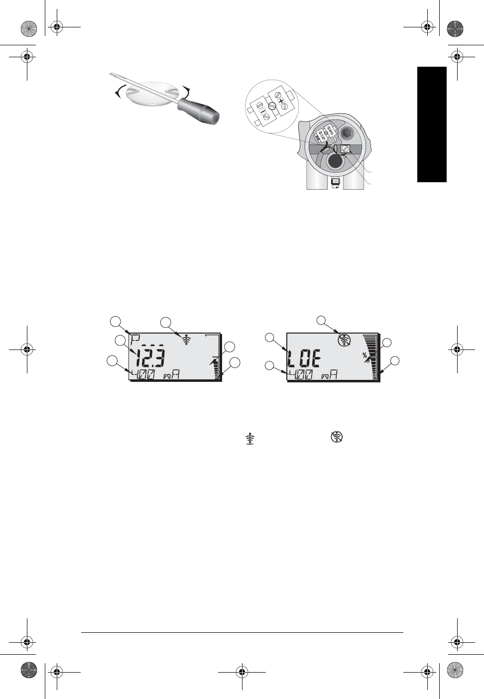
RUN Mode Display
Use the hand programmer to control the display.
Whenever a loss of echo occurs, LOE flashes and the Reliable Echo indicator is replaced by
the Unreliable indicator. Before the Failsafe Timer expires, the letters LOE (Loss of Echo)
alternate with the reading every two seconds. Once the Failsafe condition is established, LOE
is displayed permanently. When a valid reading is received, the level reading display returns to
normal operation.
1 – Primary Reading (displays level, distance, or volume, in either units or percent).
2 – Parameter for Auxiliary Reading (can be set to display milliAmp value (HART only),
distance, or confidence. It displays units, if applicable.)
4 – Echo status indicator: Reliable Echo or Unreliable Echo
5 – Units or Percent
6 – Active bar graph represents material level
7 – Auxiliary Reading
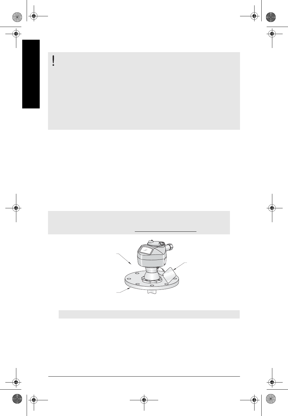
ground
lug
shield
.
Using a screwdriver for leverage if necessary,
unscrew the cover.
Connect the wires to the terminal as shown and
connect the shield to the ground lug inside the
enclosure
in
m
cm
m
Normal operation Failsafe operation
1
4
5
6
1
4
5
6
2
7
7
LR-200QS-EN.fm Page 5 Wednesday, March 12, 2003 3:51 PM
Page EN-6 SITRANS LR 200 – QUICK START MANUAL 7ML19985QL81
mmmmm
English
PROGRAM Mode Display
Programming
• Set parameters to suit your specific application.
•Activate PROGRAM mode at any time, to change parameter values and set
operating conditions.
• For local programming, use the Siemens-Milltronics hand programmer.
• If you are programming from a distance, you can use either a HART handheld
communicator or a PC running Simatic PDM.
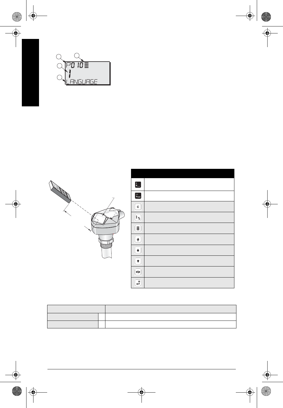
Hand programmer
For direct access to SITRANS LR 200, point the programmer at the SITRANS LR 200 display and
press the keys.
Security: (P000: Lock)
Factory setting for P069 is 1954: after a new value is entered and accepted, it becomes the
default setting.
Values Description
Value stored in P069 * Lock off: programming permitted
other Lock activated: no changes permitted
1
23
7
1– Primary Reading (displays parameter value)
2– Secondary Reading (displays parameter number)
3– Programming indicator
7– Auxiliary Reading (displays parameter names for P001 to
P010, if a language is selected. It displays the index value
for indexed parameters, such as P054).
Display
Hand-held programmer
max. 300 mm
(12")
Key Programming Mode
Decimal point
Negative value
CLEAR value
TOGGLE between Units and % on parameter
value
End PROGRAM session and enable RUN mode
Update echo quality parameters
Parameter scroll-up
Parameter scroll-down
DISPLAY opens parameter fields
ENTER the displayed value
LR-200QS-EN.fm Page 6 Wednesday, March 12, 2003 3:51 PM
7ML19985QL81 SITRANS LR 200 – QUICK START MANUAL Page EN-7
mmmmm
English
Activating SITRANS LR 200
Power up the instrument. SITRANS LR 200 starts in RUN mode.
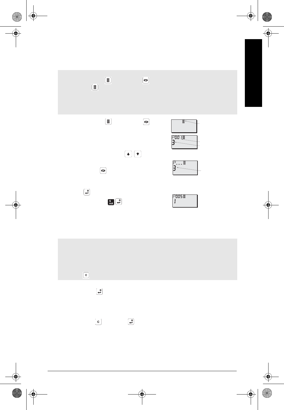
Accessing a parameter
1. Press PROGRAM then DISPLAY , to
activate PROGRAM mode.
2. Either use the ARROW keys to scroll to a
different parameter, or:
3. Press DISPLAY to open the Parameter
Number field.
4. Key in the desired parameter number followed by
ENTER .
For example: press .
The LCD displays the new parameter number and
value.
Changing a Parameter Value
1. Key in the new value.
2. Press ENTER to set the value.
Parameter Reset to Factory Default
1. Scroll to the parameter or enter its address.
2. Press CLEAR then ENTER . The value returns to the default setting.
Notes:
• Press PROGRAM then DISPLAY to access PROGRAM mode, and press
PROGRAM to return to RUN mode.
• The following instructions apply when using the Hand Programmer
• You do not need to key in initial zeros when entering a parameter number: for
example, for P005, key in 5.
Notes:
• Security must be disabled to enable programming: set P000 to the Unlocked Value
stored in P069. (A remote master can still change configuration, if P799 is set to
allow this.)
• Invalid entries will be rejected or limited.
•CLEAR can be used to clear the field.
Parameter Value
Parameter Number
PROGRAM Icon
current value
LR-200QS-EN.fm Page 7 Wednesday, March 12, 2003 3:51 PM
Page EN-8 SITRANS LR 200 – QUICK START MANUAL 7ML19985QL81
mmmmm
English
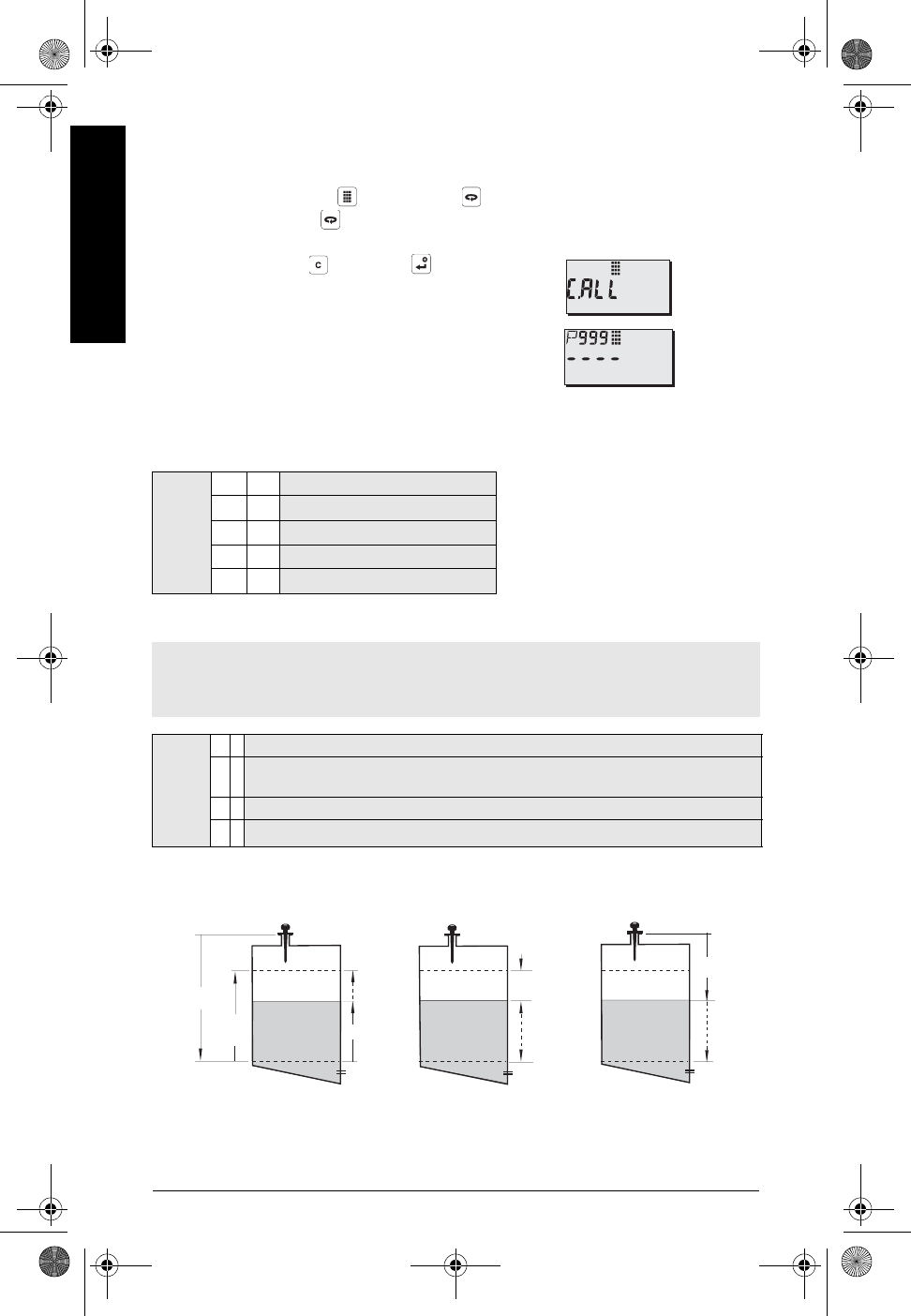
Master Reset (P999)
Returns all parameters to default settings.
1. Press PROGRAM , then DISPLAY to activate PROGRAM mode.
2. Press DISPLAY to open parameter fields.
3. Key in 999.
4. Press CLEAR then ENTER , to Clear All
and initiate reset. The LCD displays C.ALL.
5. Reset complete. (Reset takes several seconds
to complete.
Quick Setup: steps 1 to 9
1. Select language (P010: Language)
2. Set P001: Operation (measurement mode)
Value
0*
Numeric/None
1English
2German
3French
4Spanish
Notes:
• Setting P001 resets Span (P007), unless Span has previously been set to a different value.
• Changing P001 may reset Output Function (P201): this applies to HART only.
Value
0Instrument out of service.
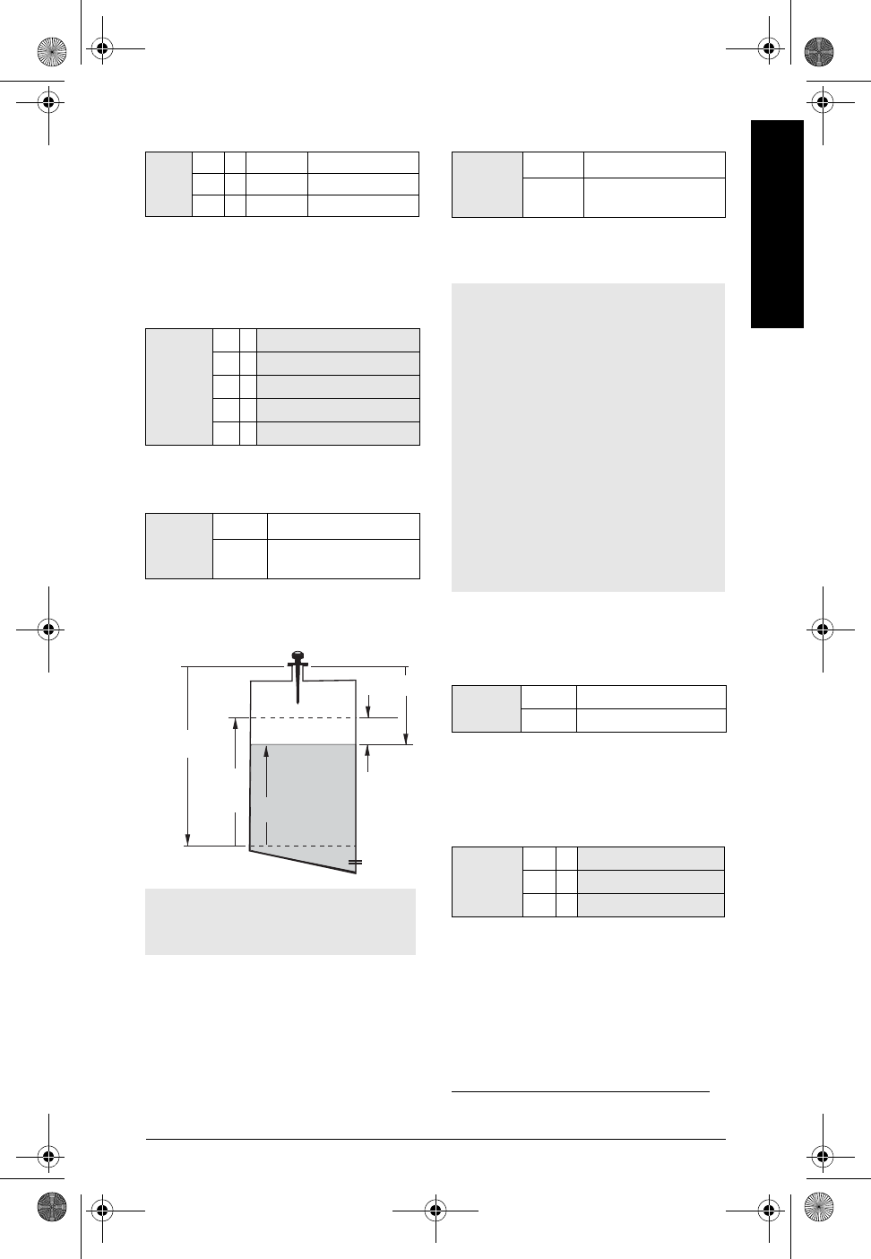
1Level returns distance to material level referenced from Empty (process empty level). The
reading is returned in volumetric units if parameters 050 to 055 are set to enable this.
2Space returns distance to material level referenced from Span (process full level).
3*
Distance returns distance to material level from reference point.
Level
(P001 = 1)Space
(P001 = 2)Distance
(P001 = 3)
Distance
Space
Level
P007
P006
100%
(20 mA)
(20 mA)
100%
0%
(4 mA)
(4 mA)
0%
100%
(20 mA)
(4 mA)
0%
Empty
Span Span
Empty
Span
Empty
mA Output with Level, Space, and Distance operation
LR-200QS-EN.fm Page 8 Wednesday, March 12, 2003 3:51 PM
corrected
7ML19985QL81 SITRANS LR 200 – QUICK START MANUAL Page EN-9
mmmmm
English
3. Set P003: Measurement Response)
Set P003 to a measurement response speed
just faster than the maximum filling or
emptying rate (whichever is greater).
4. Select measurement units (P005)
5. Set process empty level (P006:
Empty)
Empty can be set to any distance: not
necessarily the bottom of the tank.
6. Set measurement range (P007: Span)
Span can be set at any distance above
Empty level.1
.
7. Minimize false reflections: Set P838
(Auto False Echo Suppression
Distance)
Use P838 and P837 together: see step-by-
step instructions on page 10.
8. Enable False Echo Suppression: set
P837 (Auto False Echo Suppression.
Value
1slow 0.1m/minute
2*medium 1m/minute
3fast 10m/minute
Value
1*
meters
2centimeters
3millimeters
4feet
5inches
Value Range 0.0000 to 20.00
Default 20.00 m (maximum
instrument range)
Note:
• P006 and P007 are interlinked: see
notes attached to P007.
P007
P006
(100% Level)
(0% Level)
Level
Empty
Span
reference
point
Space
Distance
Values Range 0.0000 to 20.00
Default 20.00 m (but see note
below)
1. Default setting for Blanking is 0.4 m
Notes:
• Setting P006 resets Span, if it has not
previously been set to a different
value.
• The default setting for Span is based
on Operation (P001) and Empty (P006).
Span is set to Empty minus 110% of
Blanking distance1, unless Operation is
set to distance (P001=3). In this case,
Span is set to Empty distance.
• Always prevent the monitored surface
from approaching within 0.3 m (1 ft) of
the reference point, as this is the
minimum distance detectable.
Value Range: 0.0000 to 20.00 (m)
*1.000
Value
0Off
1*
Use "learned" TVT
2"Learn"
LR-200QS-EN.fm Page 9 Wednesday, March 12, 2003 3:51 PM
Page EN-10 SITRANS LR 200 – QUICK START MANUAL 7ML19985QL81
mmmmm
English
Using P837 and P838 (perform this function at low tank levels)
If SITRANS LR 200 displays an incorrect full level, or if the reading fluctuates between a false
high level and a correct level, use P838 and P837 together to elevate the TVT (Time Varying
Threshold) in this region and de-sensitize the receiver from any ‘base noise’ caused by internal
antenna reflections, nozzle echoes, or other vessel false echoes.
a. First rotate the instrument for best signal (lowest false echo amplitude)
b. Determine the distance from the reference point to the material level.
c. Select P838 and key in [distance to liquid level – 0.5m].
d. Select P837, then press 2 (Learn) and ENTER . P837 will automatically revert to 1
(use Learned TVT) after a few seconds.
9. Return to RUN
Press PROGRAM to return to RUN mode: setup is complete.
SITRANS LR 200 Communications: HART
• You will need the full manual to acquire the list of applicable parameters.
• The HART Device Descriptor (DD) may be obtained from the HART Communication
Foundation at www.hartcomm.org
• We recommend that you use Simatic Process Device Manager (PDM) to program
your instrument.
Maintenance
SITRANS LR 200 requires no maintenance or cleaning under normal operating conditions. If
cleaning becomes necessary under severe operating conditions:
1. Note the antenna material and the process medium, and select a cleaning solution
that will not react adversely with either.
2. Remove the instrument from service and wipe the antenna clean using a cloth and
suitable cleaning solution.
Notes:
• Use this function only if there is a minimum distance of 2 meters from SITRANS LR 200 to
the material.
• Set P837 and P838 during start up, if possible.
• If the vessel contains an agitator, the agitator should be running.
Note: See
mA Output with Level, Space, and Distance operation
on page 8 for an illustration
of the mA output with different modes of operation.
LR-200QS-EN.fm Page 10 Wednesday, March 12, 2003 3:51 PM
cross-referenced
7ML19985QL81 SITRANS LR 200 – QUICK START MANUAL Page EN-11
mmmmm
English
Instructions specific to hazardous area installations
(Reference European ATEX Directive 94/9/EC, Annex II, 1/0/6)
The following instructions apply to equipment covered by certificate numberxxxx:
1. For use and assembly, refer to the main instructions.
2. The equipment is certified for use as Category 1G/2G equipment.
The 1G certification covers the use of the equipment antenna or wave-guide in a
zone 0 environment at ambient temperatures of –40°C to +60°C and atmospheric
pressure up to the process flange. The 2G certification covers the remainder of the
equipment for use in a zone 1 environment.
3. The equipment may be used with flammable gases and vapors with apparatus group
IIC and temperature class T6.
4. The equipment is certified for use in an ambient temperature range of–40°C to 60°C.
5. The equipment has not been assessed as a safety related device (as referred to by
Directive 94/9/EC Annex II, clause 1.5).
6. Installation and inspection of this equipment shall be carried out by suitably trained
personnel in accordance with the applicable code of practice (EN 60079-14 and
EN 60079-17 in Europe).
7. Repair of this equipment shall be carried out by suitably trained personnel in
accordance with the applicable code of practice (e.g. EN 60079-19 within Europe).
8. Components to be incorporated into or used as replacements in the equipment shall
be fitted by suitably trained personnel in accordance with the manufacturer’s
documentation.
9. The equipment has been tested in accordance with MIL Standard D0160B for the
following vibration levels:
Frequency range 15–54Hz, 0.010 inch displacement
Frequency range 54–2000 Hz, 1.5 g of acceleration.
These were randomly cycled for a period of 2 hours.
10. The certification of this equipment relies upon the following materials used in its
construction:
Aluminum alloy A-356 T6 (aluminum enclosure option)
Stainless steel CF8M (stainless steel enclosure option)
Stycast 2651-40FR encapsulant, catalyst II
Stycast LA-9823-76 epoxy cement
Tempered glass (window)
If the equipment is likely to come into contact with aggressive substances, then it is the
responsibility of the user to take suitable precautions that prevent it from being adversely
affected, thus ensuring that the type of protection is not compromised.
LR-200QS-EN.fm Page 11 Wednesday, March 12, 2003 3:51 PM

Page 12 ILE-37 Sensing Head – INSTRUCTION MANUAL 7ML19981CW01
Aggressive substances: e.g. acidic liquids or gases that may attack metals, or
solvents that may affect polymeric materials.
Suitable precautions: e.g. regular checks as part of routine inspections or
establishing from the material’s data sheet that it is
resistant to specific chemicals.
11. Equipment Marking
The equipment marking contains at least the information on the product label, shown on
the inside front cover of this manual.
LR-200QS-EN.fm Page 12 Wednesday, March 12, 2003 3:51 PM