Siemens Canada Siemens Milltronics Process Instruments LR250DE SITRANS LR250 User Manual JE03 LR250 LUI
Siemens Canada Ltd. - Siemens Milltronics Process Instruments SITRANS LR250 JE03 LR250 LUI
UserManual.wiki
>
Siemens Canada Siemens Milltronics Process Instruments
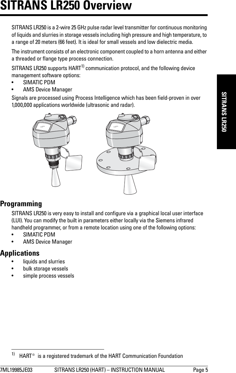
>
LR250DE User Manual
User Manual
Navigation menu
Upload a User Manual
Namespaces
Wiki Guide
HTML
PDF
Info
Views
User Manual
Discussion / Help
Navigation
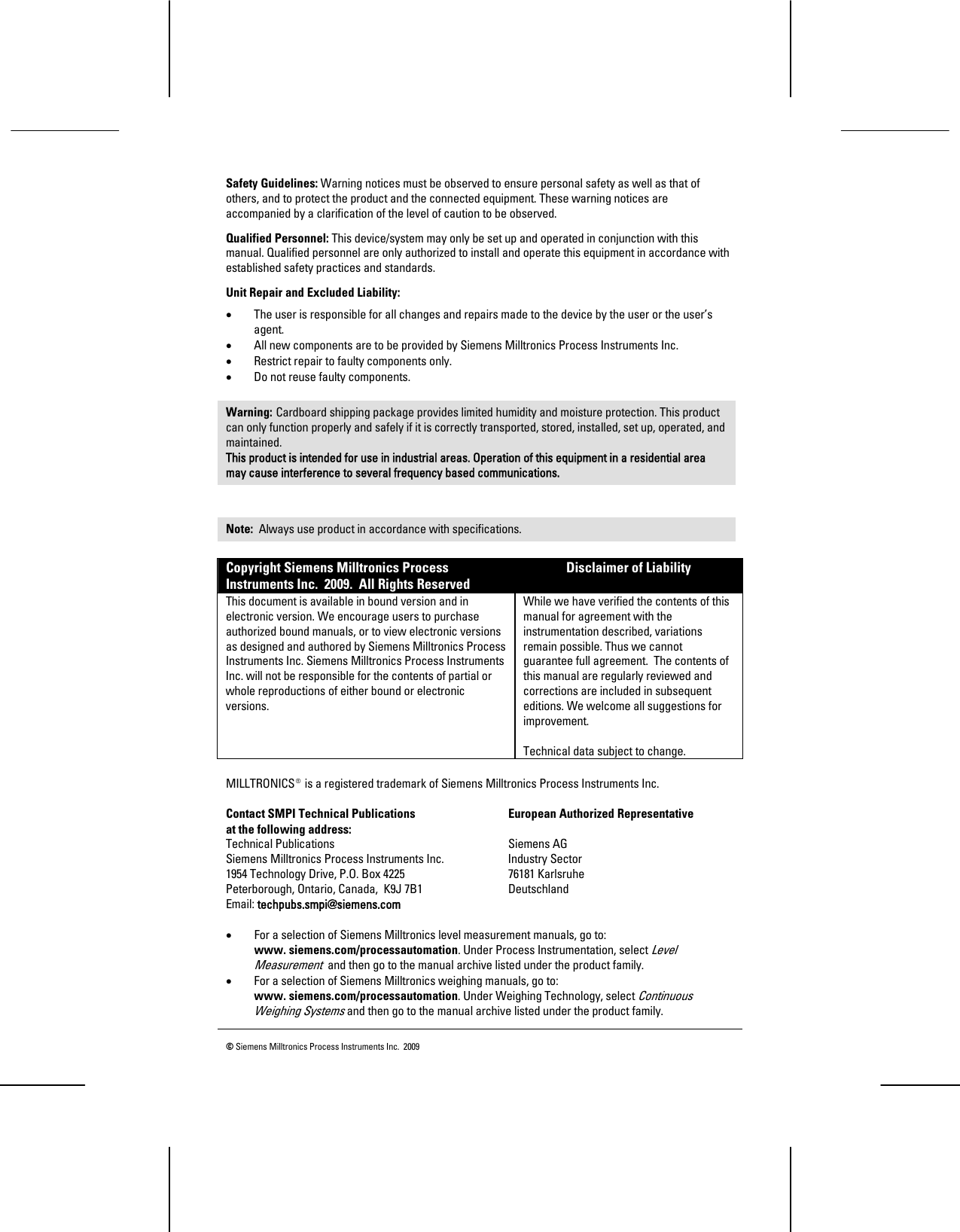
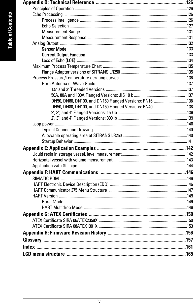
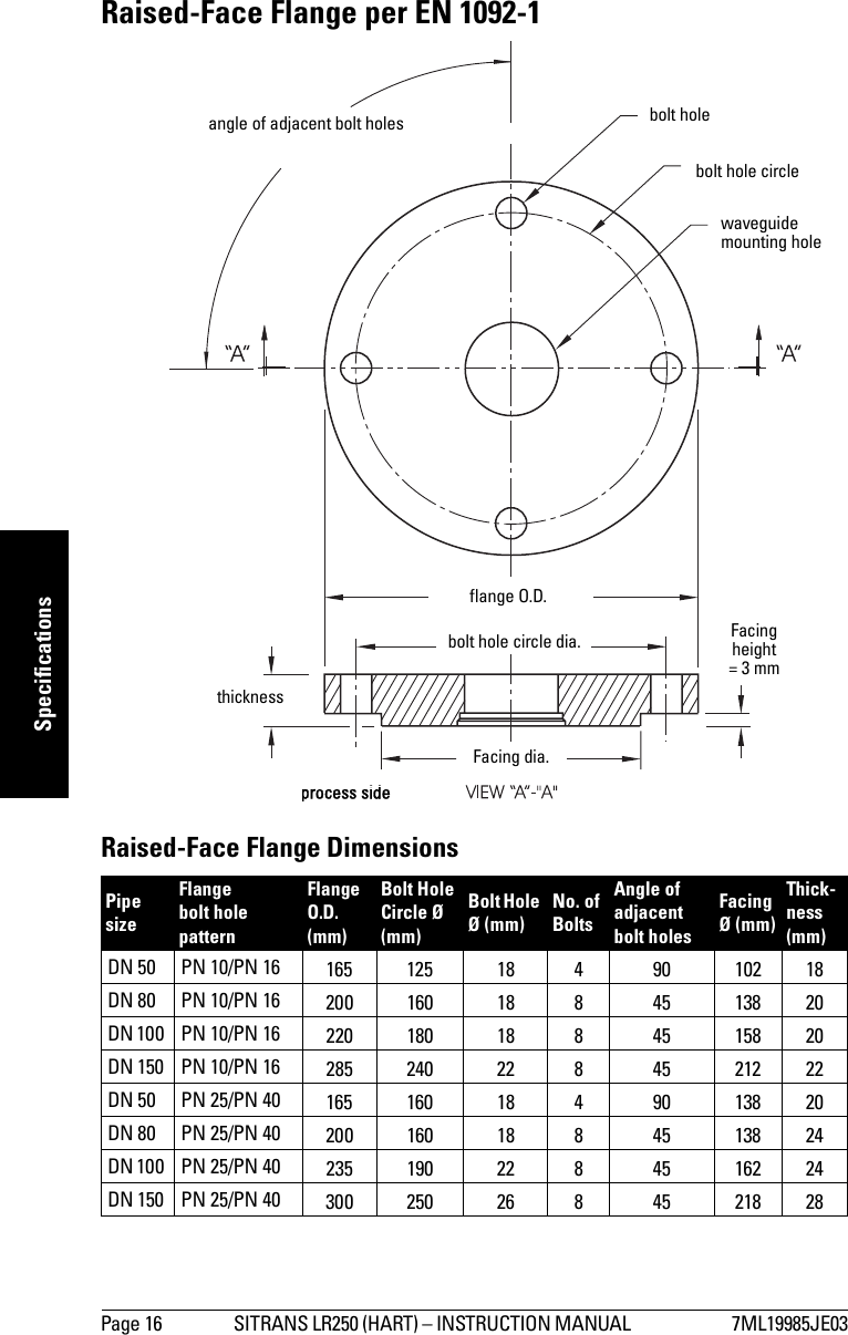
![7ML19985JE03 SITRANS LR250 (HART) – INSTRUCTION MANUAL Page 17mmmmmSpecificationsRaised-Face Flange markingsThe flange markings are located around the outside edge of the flange.Serial number: a unique number allotted to each flange, including the date of manufacture (MMDDYY) followed by a number from 001 to 999.Flange series: the Siemens Milltronics drawing identification.Heat code: a flange material batch code identification.Flat-Face FlangeSee Flat-Face Flange Dimensions on page 18 for details.Blind Flange Markings(Optional Manufacturer’s Logo [optional]; Flange Standard; Nominal Size; Material; Heat Code)Machining Identification Welded Assembly Identificationa)a) When flange material is Alloy N06022/2.4602, additional material and heat code identification is provided.Serial no. Logo Flange seriesFlange seriesHeatCode no. FacingManufacturer’s logo; EN 1092-1 05 ’B1’; ’DN50’ ’PN16’ ’1.4404 or 1.4435’ A1B2C3 mmddyyxxx XXXXX XXXXX A1B2C3 RFprocess sideenclosure mounting hole bolt holeflange O.D.bolt hole circlethickness](https://usermanual.wiki/Siemens-Canada-Siemens-Milltronics-Process-Instruments/LR250DE/User-Guide-1072778-Page-23.png)
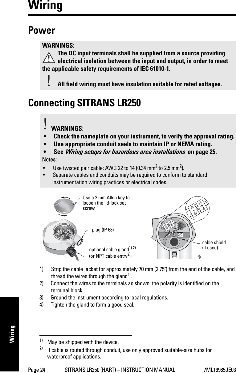
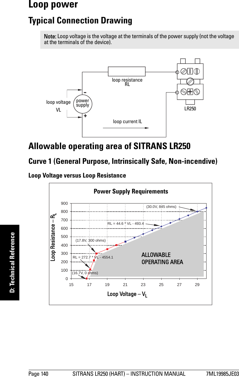
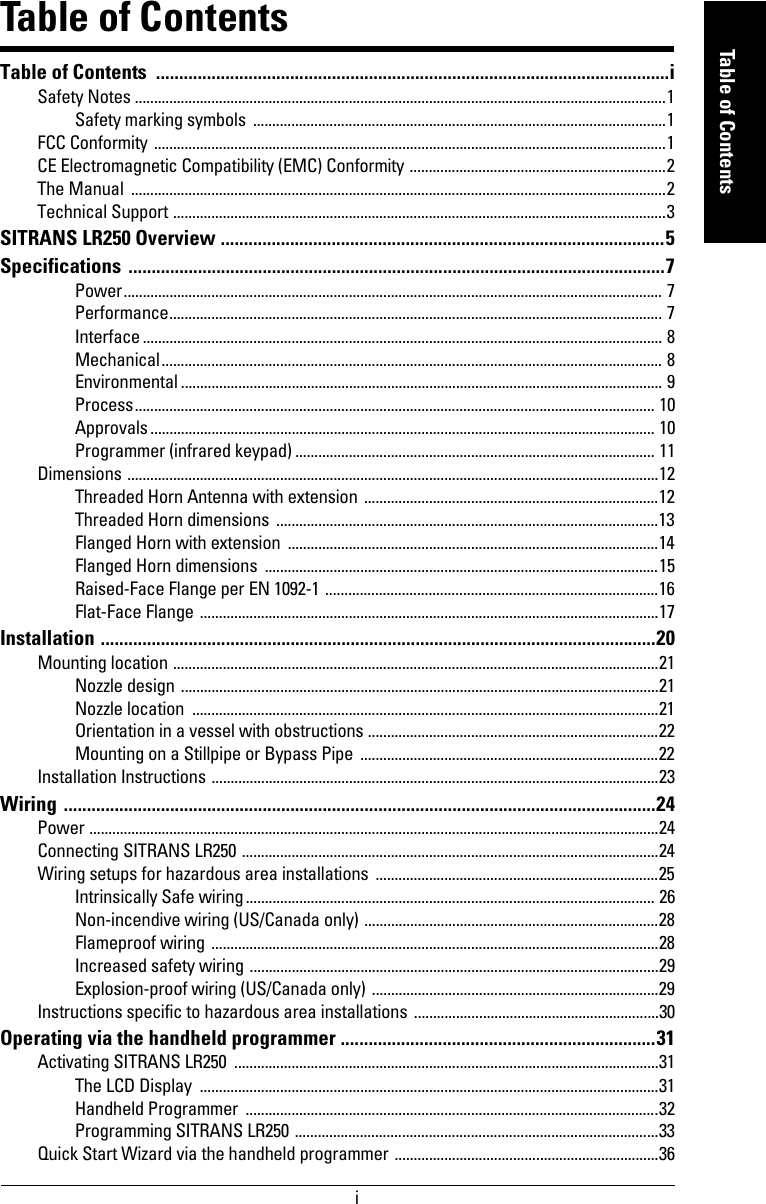
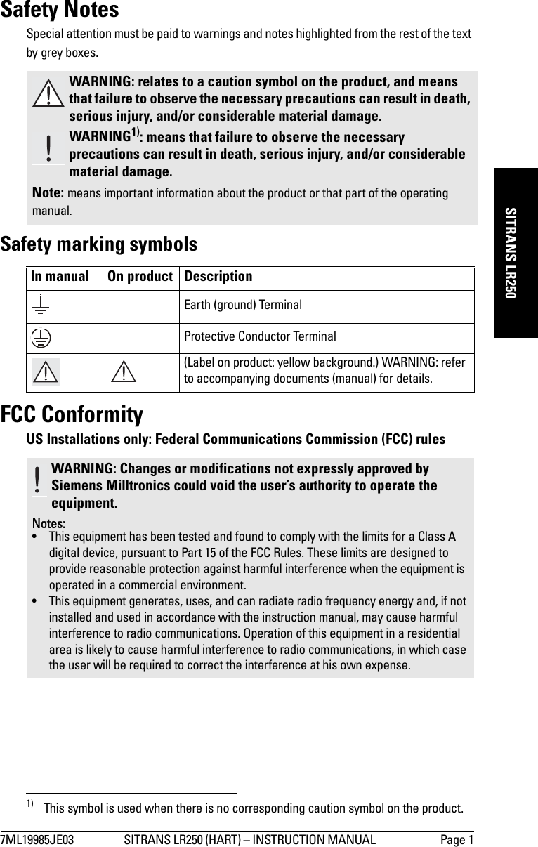
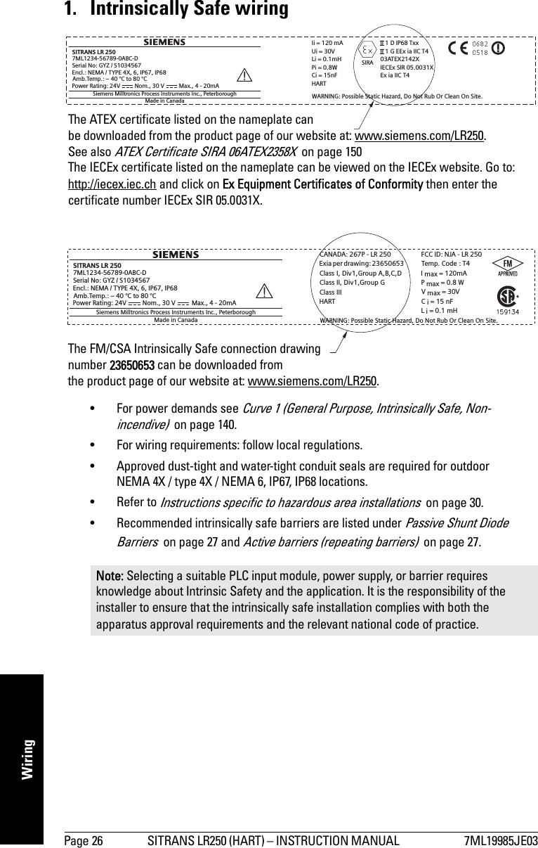
![7ML19985JE03 SITRANS LR250 (HART) – INSTRUCTION MANUAL Page 25mmmmmWiringConnecting HART1)2)Wiring setups for hazardous area installationsThere are five wiring options for hazardous area installations:•Intrinsically Safe wiring on page 26•Non-incendive wiring (US/Canada only) on page 28•Flameproof wiring on page 28•Increased safety wiring on page 29•Explosion-proof wiring (US/Canada only) on page 29In all cases, check the nameplate on your instrument, and confirm the approval rating.1) Depending on the system design, the power supply may be separate from the PLC, or integral to it.2) HART resistance (total loop resistance, that is, cable resistance plus 250 Ohm [resistor]) must be limited according to the allowable operating area as shown in either Curve 1 (General Purpose, Intrinsically Safe, Non-incendive) on page 140 or Curve 2 (Flameproof, Increased Safety, Explosion-proof) on page 141.active PLCHART modemSITRANS LR250power supply (1)Typical PLC/mA configuration with HARTR= 250 Ω (2)HART communicator](https://usermanual.wiki/Siemens-Canada-Siemens-Milltronics-Process-Instruments/LR250DE/User-Guide-1072778-Page-31.png)
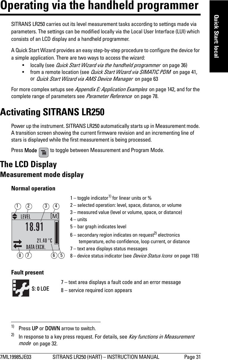
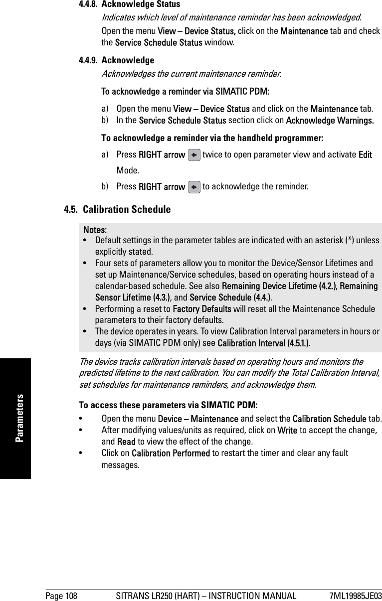
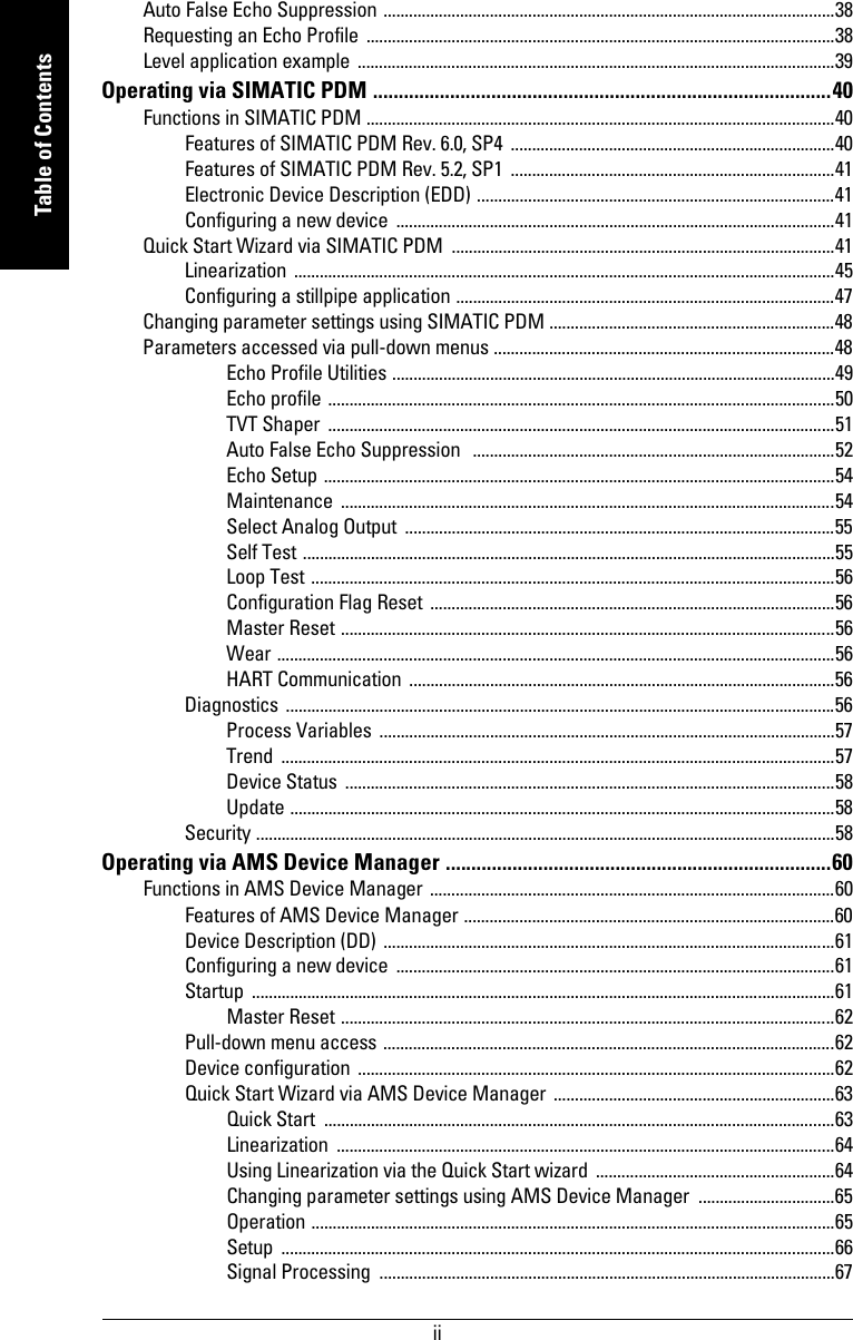
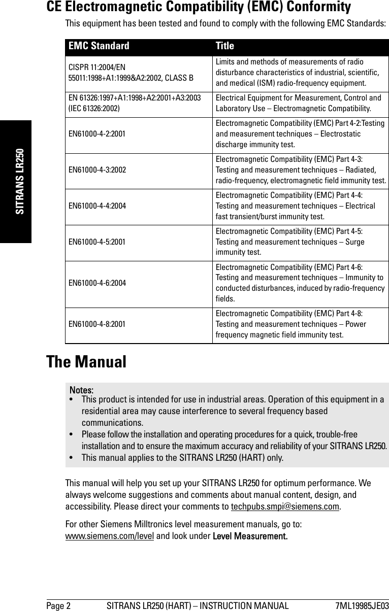
![7ML19985JE03 SITRANS LR250 (HART) – INSTRUCTION MANUAL Page 39mmmmmQuick Start: localLevel application exampleThe application is a vessel that takes an average 3 hours (180 minutes) to fill and 3 weeks to empty.Fill rate = 0.08 m/minute [(Low Cal Pt. minus High Cal Pt.) / fastest of fill or empty time]= (15.5 m – 1 m) / 180 min. = 14.5 m /180 min. = 0.08 m/min.Quick Start Parameter Setting Description Material (1.2.) LIQUIDResponse Rate (1.3.) SLOW Resets Fill Rate and Empty Rate to 0.1 m/minute.Units (1.4.) mOperation Mode (1.5.) LEVEL Material level referenced from Low Cal. Point.Low Calibration Point (1.6.) 15.5 Process empty level.High Calibration Point (1.7.) 1.0 Process full level.Apply? (Apply changes) (1.8.) YES Save new settings.sensor reference point Level Low Cal. PointHigh Cal. Point15.5 m1.0 mSITRANS LR250](https://usermanual.wiki/Siemens-Canada-Siemens-Milltronics-Process-Instruments/LR250DE/User-Guide-1072778-Page-45.png)
![Page 56 SITRANS LR250 (HART) – INSTRUCTION MANUAL 7ML19985JE03mmmmmSIMATIC PDMLoop TestAllows you to input a simulated value (4 mA, 20 mA, or a user-defined value) in order to test the functioning of the mA connections during commissioning or maintenance of the device. (The range is 3.56 mA to 22.6 mA: see mA Output Value (2.6.6.) on page 86.)To simulate a user-defined mA value:1) Open the menu Device – Loop Test. 2) Select Other, enter the new value, and click on OK. The message ’Field Device fixed at [new value]’ appears. Click on OK. The Loop Test window remains open.3) When you are ready to end simulation, select End and click on OK to return the device to the actual output value.Configuration Flag ResetTo reset the configuration flag to zero, open the menu Device – Configuration Flag Reset and perform a reset.Master ResetFactory DefaultsFactory Defaults resets all parameters to the default settings with the following exceptions: • Device Address• Write Protect and PIN to unlock• Learned TVT curve1) Open the menu Device – Master Reset, select Yes, and click on OK to perform a reset to Factory Defaults.2) After the reset is complete upload parameters to the PC/PG. (If you are performing a reset after replacing the device with a different instrument, do not upload parameters to the PC/PG).WearReports the number of hours the device has been operating, and the number of times it has been powered up.Open the menu Device – Wear to view:• Powered Days• Power-on ResetsHART CommunicationSets the number of request/response preambles (default 5).We recommend you do not change this value. DiagnosticsYou can monitor level/volume trends, electronics temperature, and device status.Note: The simulated AO (Analog Output) value influences output to the control system.](https://usermanual.wiki/Siemens-Canada-Siemens-Milltronics-Process-Instruments/LR250DE/User-Guide-1072778-Page-62.png)
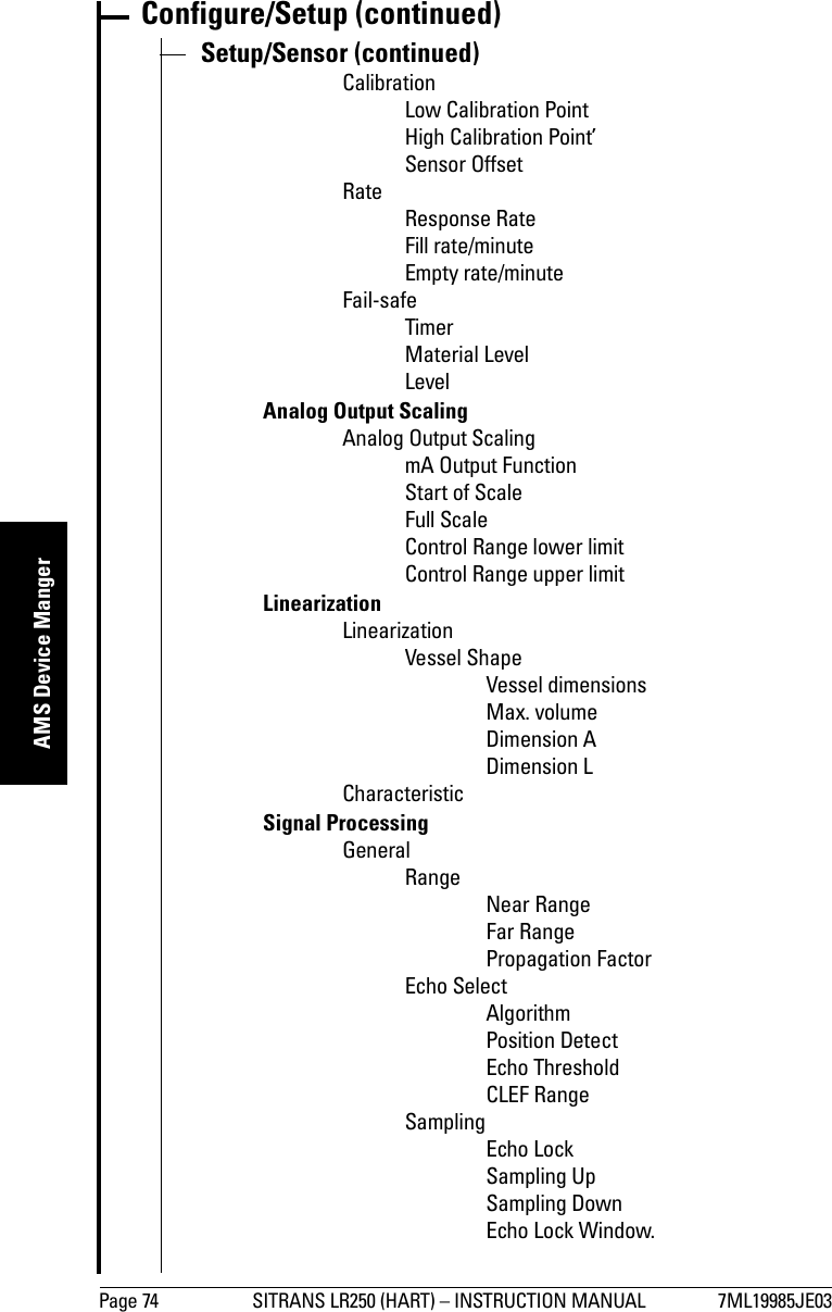
![Page 66 SITRANS LR250 (HART) – INSTRUCTION MANUAL 7ML19985JE03mmmmmAMS Device MangerSetupSensor Navigate to Configure/Setup > Setup and click on Sensor for access to:General [see Sensor (2.2.) on page 79]•Units• Operating Mode•Material• Damping Filter• Antenna (read only)Calibration [see Calibration (2.3.) on page 80]• Low Calibration Point• High Calibration Point• Sensor OffsetRate [see Rate (2.4.) on page 81]• Response Rate• Fill rate/minute• Empty rate/minuteFail-safe [see Fail-safe (2.5.) on page 83]• Material level•Timer•LevelNote: For more detailed explanations of the parameters listed below see the pages referenced.](https://usermanual.wiki/Siemens-Canada-Siemens-Milltronics-Process-Instruments/LR250DE/User-Guide-1072778-Page-72.png)
![7ML19985JE03 SITRANS LR250 (HART) – INSTRUCTION MANUAL Page 67mmmmmAMS Device MangerAnalog Output ScalingNavigate to Configure/Setup > Setup and click on Analog Output Scaling for access to:Analog Output Scaling [see Analog Output Scaling (2.6.) on page 84]• mA Output Function• Start of scale• Full Scale• Control Range (lower limit)• Control Range (upper limit)Signal Processing](https://usermanual.wiki/Siemens-Canada-Siemens-Milltronics-Process-Instruments/LR250DE/User-Guide-1072778-Page-73.png)
![Page 68 SITRANS LR250 (HART) – INSTRUCTION MANUAL 7ML19985JE03mmmmmAMS Device MangerSignal Processing (continued)GeneralNavigate to Configure/Setup > Setup > Signal Processing and click on General for access to:Range [see Signal Processing (2.8.) on page 90]•Near Range• Far Range• Propagation FactorEcho Select [see Echo select (2.8.4.) on page 91]• Algorithm• Position Detect• Echo Threshold• CLEF RangeSampling [see Sampling (2.8.5.) on page 92]• Echo Lock• Sampling Up• Sampling Down• Echo Lock WindowSignal Quality• Confidence• Echo Strength•Noise Average•Noise PeakTVTModify the TVT to screen out false echoes [see Auto False Echo Suppression (2.8.7.1.) on page 130].](https://usermanual.wiki/Siemens-Canada-Siemens-Milltronics-Process-Instruments/LR250DE/User-Guide-1072778-Page-74.png)
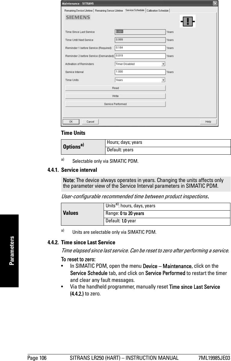
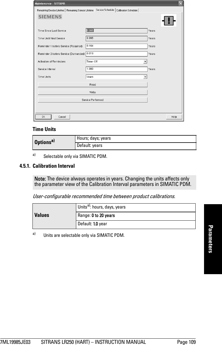
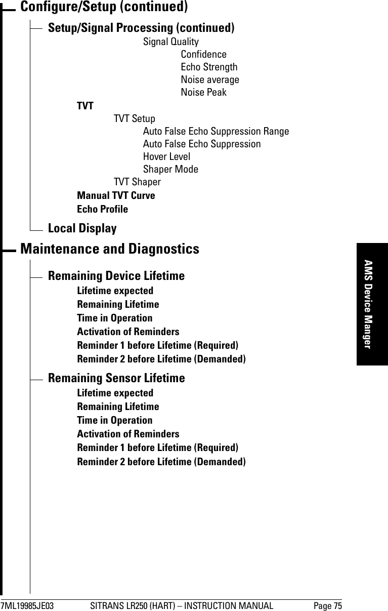
![7ML19985JE03 SITRANS LR250 (HART) – INSTRUCTION MANUAL Page 69mmmmmAMS Device MangerNavigate to Configure/Setup > Setup > Signal Processing and click on TVT. Click on one of the two tabs to access the parameters listed:TVT Setup [see TVT setup (2.8.7.) on page 94]• Auto False Echo Suppression Range• Auto False Echo Suppression•Hover Level• Shaper ModeTVT Shaper• Shaper breakpoints 1 to 40. (Turn TVT Setup/Shaper Mode on to activate.)Manual TVT Curve Displays the effects of the TVT shaper modifications. Navigate to Configure/Setup > Setup > Signal Processing and click on Manual TVT Curve.Echo Profile• Navigate to Configure/Setup > Setup > Signal Processing and click on Echo Profile.• Select Standard operation for faster display.Local Display Navigate to Configure/Setup > Setup > Local Display for access to: • Language• LCD Fast Mode [see LCD Fast Mode (4.9.) on page 112]• LCD Contrast [see LCD Contrast (4.10.) on page 112]Maintenance and DiagnosticsNavigate to Maintenance and Diagnostics for access to: Remaining Device Lifetime [see Remaining Device Lifetime (4.2.) on page 99]• Lifetime expected• Remaining Lifetime• Time in Operation• Activation of Reminders• Reminder 1 before Lifetime (Required)• Reminder 2 before Lifetime (Demanded)Remaining Sensor Lifetime [see Remaining Sensor Lifetime (4.3.) on page 102]• Lifetime expected• Remaining Lifetime• Time in Operation• Activation of Reminders• Reminder 1 before Lifetime (Required)• Reminder 2 before Lifetime (Demanded)Service Schedule [see Service Schedule (4.4.) on page 105]•Service Interval• Time since last Service• Time until next Service• Activation of Reminders• Reminder 1 before Service (Required)• Reminder 2 before Service (Demanded)](https://usermanual.wiki/Siemens-Canada-Siemens-Milltronics-Process-Instruments/LR250DE/User-Guide-1072778-Page-75.png)
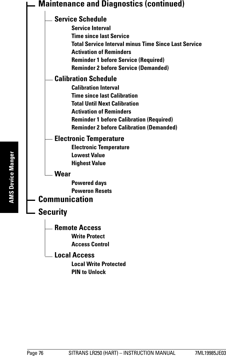
![Page 70 SITRANS LR250 (HART) – INSTRUCTION MANUAL 7ML19985JE03mmmmmAMS Device MangerCalibration Schedule [see Calibration Schedule (4.5.) on page 108]• Calibration Interval• Time since last Calibration• Time Until Next Calibration• Activation of Reminders• Reminder 1 before Calibration (Required)• Reminder 2 before Calibration (Demanded)Electronic Temperature• Electronic Temperature •Lowest Value• Highest ValueWear (see Wear on page 56)• Powered days•Poweron ResetsCommunicationNavigate to Communication to read the following: Tag; Manufacturer’s ID; Device ID; Product ID; Device Revision; EDD Revision; Universal CommandSecurityNavigate to Configure/Setup > Security to access:Remote Access [see Remote Access (6.1.) on page 113]• Write Protect (read only)• Access ControlLocal Access [see Local Access (6.2.) on page 114]• Local Write Protected• PIN to UnlockSee also Password Protection on page 72Note: If access control is changed to limit remote access, it can only be reset via the handheld programmer. See Ac cess C ontrol ( 6.1.1.) on page 113.](https://usermanual.wiki/Siemens-Canada-Siemens-Milltronics-Process-Instruments/LR250DE/User-Guide-1072778-Page-76.png)
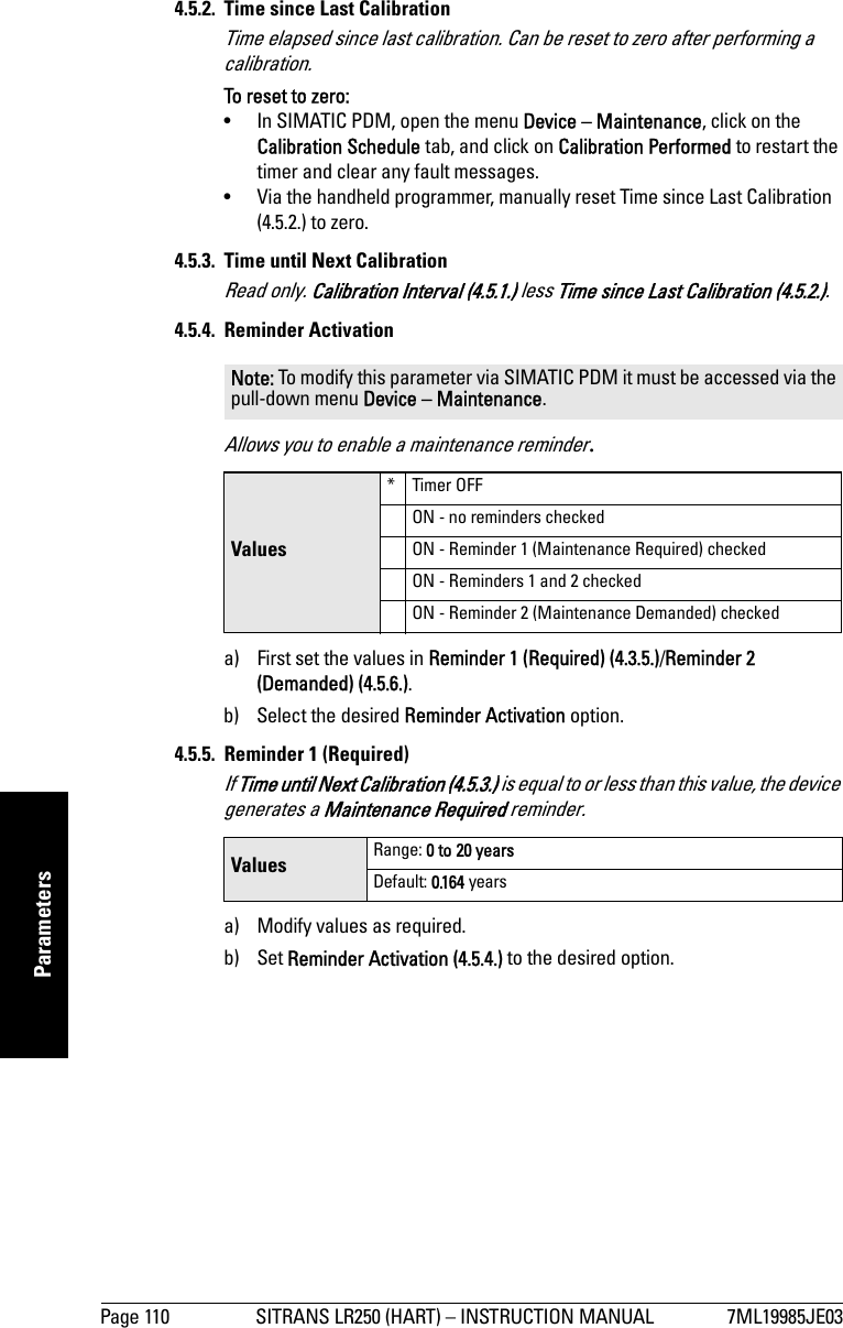
![7ML19985JE03 SITRANS LR250 (HART) – INSTRUCTION MANUAL Page 83mmmmmParameters2.5. Fail-safe2.5.1. Material LevelDefines the mA output to use when the Fail-safe Timer expires.2.5.2. TimerSets the time to elapse since the last valid reading, before the Fail-safe Level is reported.2.5.3. LevelAllows the user to define the mA value to be reported when the Fail-safe timer expires. Note: Default settings in the parameter tables are indicated with an asterisk (*) unless explicitly stated.Note: The default setting depends whether your device is a standard or NAMUR NE 43-compliant device.STANDARD DEVICEOptions HI 20.5 mA (max. mA Limit) LO 3.8 mA (min. mA Limit) *HOLDLast valid reading (default 22.6 mA)VALUE User-selected value [defined in Level (2.5.3.)]NAMUR NE 43-COMPLIANT DEVICEOptions HI 20.5 mA (max. mA Limit) LO 3.8 mA (min. mA Limit) HOLD Last valid reading * VALUE User-selected value [defined in Level (2.5.3.): default 3.58 mA]Note: When a Loss of Echo occurs Material Level (2.5.1.) determines the material level to be reported when the Fail-safe timer expires. See Loss of Echo (LOE) on page 134 for more detail.Values Range: 0.00 to 7200 secondsDefault: 100 sNotes:• The default setting depends whether your device is a standard or NAMUR NE 43-compliant device.•Material Level (2.5.1.) must be set to VALUE to enable the Level value to be reported.Device Type STANDARD NAMUR NE43- COMPLIANTValues Range 3.56 mA to 22.6 mADefault 22.60 mA 3.58 mA](https://usermanual.wiki/Siemens-Canada-Siemens-Milltronics-Process-Instruments/LR250DE/User-Guide-1072778-Page-89.png)
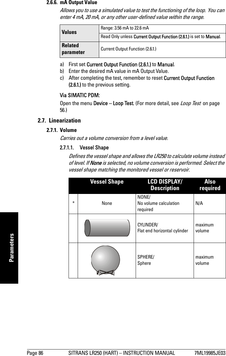
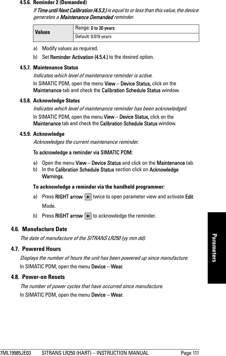
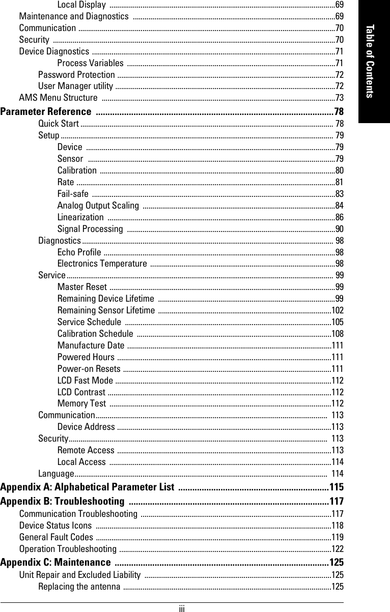
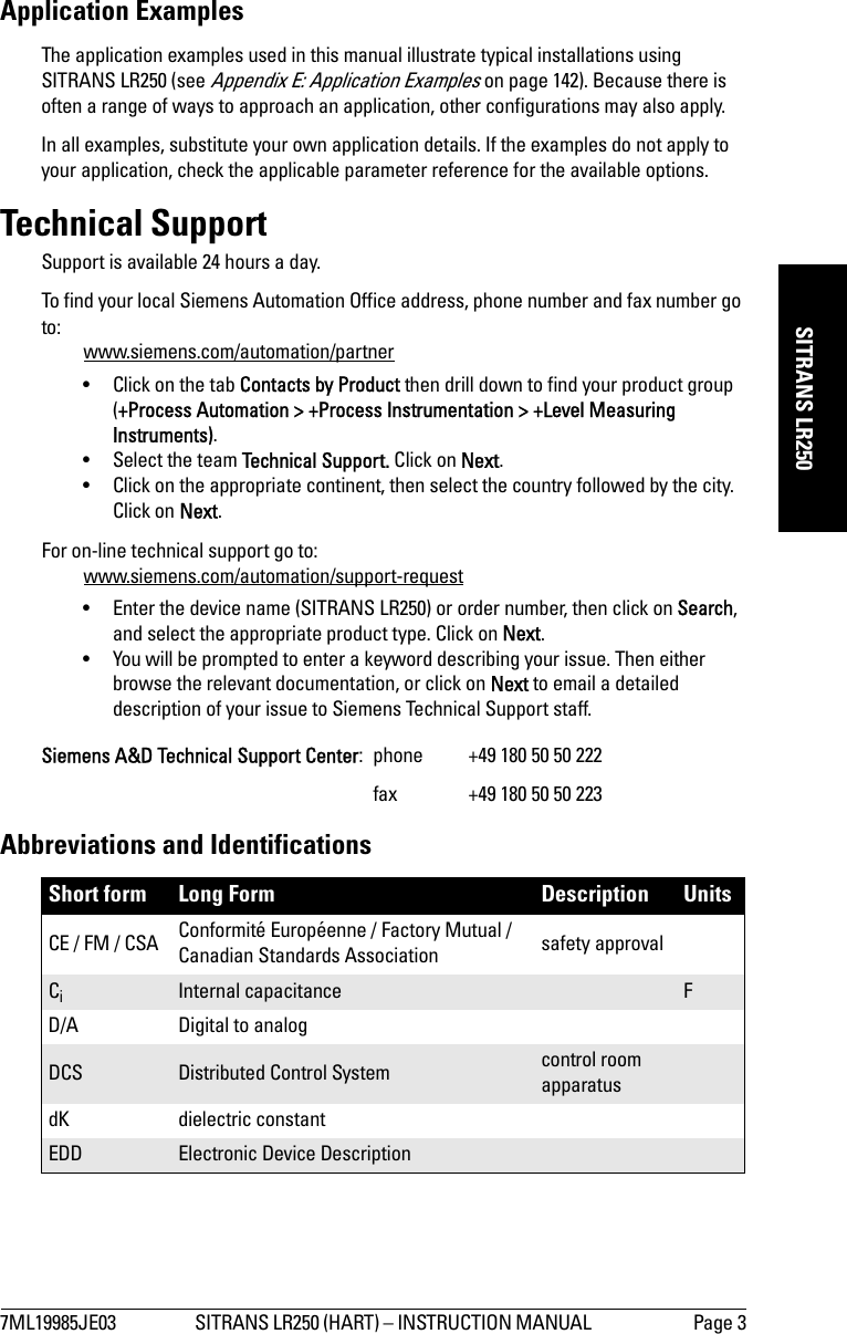
![7ML19985JE03 SITRANS LR250 (HART) – INSTRUCTION MANUAL Page 87mmmmmParametersLINEAR/Upright, linear (flat bottom) maximum volumeCONICAL BOT/Conical or pyramidal bottommaximum volume, dimension APARABOLIC BOT/Parabolic bottommaximum volume, dimension AHALF SPHERE BOT/Half-sphere bottommaximum volume, dimension AFLAT SLOPED BOT/Flat sloped bottom maximum volume, dimension APARABOLIC ENDS/Parabolic end horizontal cyl-indermaximum volume, dimension A, dimension LLINEAR TABLEa)/Linearization table(level/volume breakpoints)maximum volume, tables 1-32 level and volume break-pointsa) Linearization Table must be selected in order for level/volume values [see Table 1-8 (2.7.2.)] to be transferred.Vessel Shape (cont’d)LCD DISPLAY/DescriptionAlso required AAAAAL](https://usermanual.wiki/Siemens-Canada-Siemens-Milltronics-Process-Instruments/LR250DE/User-Guide-1072778-Page-93.png)