Siemens Canada Siemens Milltronics Process Instruments LR250DE SITRANS LR250 User Manual JE03 LR250 LUI
Siemens Canada Ltd. - Siemens Milltronics Process Instruments SITRANS LR250 JE03 LR250 LUI
User Manual
Instruction Manual January 2009
LR250 (HART)
sitrans

© Siemens Milltronics Process Instruments Inc. 2009
Safety Guidelines: Warning notices must be observed to ensure personal safety as well as that of
others, and to protect the product and the connected equipment. These warning notices are
accompanied by a clarification of the level of caution to be observed.
Qualified Personnel: This device/system may only be set up and operated in conjunction with this
manual. Qualified personnel are only authorized to install and operate this equipment in accordance with
established safety practices and standards.
Unit Repair and Excluded Liability:
• The user is responsible for all changes and repairs made to the device by the user or the user’s
agent.
• All new components are to be provided by Siemens Milltronics Process Instruments Inc.
• Restrict repair to faulty components only.
• Do not reuse faulty components.
Warning: Cardboard shipping package provides limited humidity and moisture protection. This product
can only function properly and safely if it is correctly transported, stored, installed, set up, operated, and
maintained.
This product is intended for use in industrial areas. Operation of this equipment in a residential area
may cause interference to several frequency based communications.
Note: Always use product in accordance with specifications.
Copyright Siemens Milltronics Process
Instruments Inc. 2009. All Rights Reserved
Disclaimer of Liability
This document is available in bound version and in
electronic version. We encourage users to purchase
authorized bound manuals, or to view electronic versions
as designed and authored by Siemens Milltronics Process
Instruments Inc. Siemens Milltronics Process Instruments
Inc. will not be responsible for the contents of partial or
whole reproductions of either bound or electronic
versions.
While we have verified the contents of this
manual for agreement with the
instrumentation described, variations
remain possible. Thus we cannot
guarantee full agreement. The contents of
this manual are regularly reviewed and
corrections are included in subsequent
editions. We welcome all suggestions for
improvement.
Technical data subject to change.
MILLTRONICS®is a registered trademark of Siemens Milltronics Process Instruments Inc.
Contact SMPI Technical Publications European Authorized Representative
at the following address:
Technical Publications Siemens AG
Siemens Milltronics Process Instruments Inc. Industry Sector
1954 Technology Drive, P.O. Box 4225 76181 Karlsruhe
Peterborough, Ontario, Canada, K9J 7B1 Deutschland
Email: techpubs.smpi@siemens.com
• For a selection of Siemens Milltronics level measurement manuals, go to:
www. siemens.com/processautomation. Under Process Instrumentation, select
Level
Measurement
and then go to the manual archive listed under the product family.
• For a selection of Siemens Milltronics weighing manuals, go to:
www. siemens.com/processautomation. Under Weighing Technology, select
Continuous
Weighing Systems
and then go to the manual archive listed under the product family.

i
mmmmm
Table of Content s
Table of Contents
Table of Contents ...............................................................................................................i
Safety Notes ...........................................................................................................................................1
Safety marking symbols ............................................................................................................1
FCC Conformity ......................................................................................................................................1
CE Electromagnetic Compatibility (EMC) Conformity ...................................................................2
The Manual ............................................................................................................................................2
Technical Support .................................................................................................................................3
SITRANS LR250 Overview ................................................................................................5
Specifications ....................................................................................................................7
Power............................................................................................................................................. 7
Performance................................................................................................................................. 7
Interface ........................................................................................................................................ 8
Mechanical................................................................................................................................... 8
Environmental .............................................................................................................................. 9
Process........................................................................................................................................ 10
Approvals .................................................................................................................................... 10
Programmer (infrared keypad) .............................................................................................. 11
Dimensions ...........................................................................................................................................12
Threaded Horn Antenna with extension .............................................................................12
Threaded Horn dimensions ....................................................................................................13
Flanged Horn with extension .................................................................................................14
Flanged Horn dimensions .......................................................................................................15
Raised-Face Flange per EN 1092-1 .......................................................................................16
Flat-Face Flange ........................................................................................................................17
Installation ........................................................................................................................20
Mounting location ...............................................................................................................................21
Nozzle design .............................................................................................................................21
Nozzle location ..........................................................................................................................21
Orientation in a vessel with obstructions ............................................................................22
Mounting on a Stillpipe or Bypass Pipe ..............................................................................22
Installation Instructions .....................................................................................................................23
Wiring ................................................................................................................................24
Power .....................................................................................................................................................24
Connecting SITRANS LR250 .............................................................................................................24
Wiring setups for hazardous area installations ..........................................................................25
Intrinsically Safe wiring ........................................................................................................... 26
Non-incendive wiring (US/Canada only) .............................................................................28
Flameproof wiring .....................................................................................................................28
Increased safety wiring ...........................................................................................................29
Explosion-proof wiring (US/Canada only) ...........................................................................29
Instructions specific to hazardous area installations ................................................................30
Operating via the handheld programmer ....................................................................31
Activating SITRANS LR250 ...............................................................................................................31
The LCD Display ........................................................................................................................31
Handheld Programmer ............................................................................................................32
Programming SITRANS LR250 ...............................................................................................33
Quick Start Wizard via the handheld programmer .....................................................................36

ii
mmmmm
Table of Cont ent s
Auto False Echo Suppression ..........................................................................................................38
Requesting an Echo Profile ..............................................................................................................38
Level application example ................................................................................................................39
Operating via SIMATIC PDM .........................................................................................40
Functions in SIMATIC PDM ..............................................................................................................40
Features of SIMATIC PDM Rev. 6.0, SP4 ............................................................................40
Features of SIMATIC PDM Rev. 5.2, SP1 ............................................................................41
Electronic Device Description (EDD) ....................................................................................41
Configuring a new device .......................................................................................................41
Quick Start Wizard via SIMATIC PDM ..........................................................................................41
Linearization ...............................................................................................................................45
Configuring a stillpipe application .........................................................................................47
Changing parameter settings using SIMATIC PDM ...................................................................48
Parameters accessed via pull-down menus ................................................................................48
Echo Profile Utilities ........................................................................................................49
Echo profile .......................................................................................................................50
TVT Shaper .......................................................................................................................51
Auto False Echo Suppression .....................................................................................52
Echo Setup ........................................................................................................................54
Maintenance ....................................................................................................................54
Select Analog Output .....................................................................................................55
Self Test .............................................................................................................................55
Loop Test ...........................................................................................................................56
Configuration Flag Reset ...............................................................................................56
Master Reset ....................................................................................................................56
Wear ...................................................................................................................................56
HART Communication ....................................................................................................56
Diagnostics .................................................................................................................................56
Process Variables ...........................................................................................................57
Trend ..................................................................................................................................57
Device Status ...................................................................................................................58
Update ................................................................................................................................58
Security ........................................................................................................................................58
Operating via AMS Device Manager ...........................................................................60
Functions in AMS Device Manager ...............................................................................................60
Features of AMS Device Manager .......................................................................................60
Device Description (DD) ..........................................................................................................61
Configuring a new device .......................................................................................................61
Startup .........................................................................................................................................61
Master Reset ....................................................................................................................62
Pull-down menu access ..........................................................................................................62
Device configuration ................................................................................................................62
Quick Start Wizard via AMS Device Manager ..................................................................63
Quick Start ........................................................................................................................63
Linearization .....................................................................................................................64
Using Linearization via the Quick Start wizard ........................................................64
Changing parameter settings using AMS Device Manager ................................65
Operation ...........................................................................................................................65
Setup ..................................................................................................................................66
Signal Processing ...........................................................................................................67

iii
mmmmm
Table of Content s
Local Display ....................................................................................................................69
Maintenance and Diagnostics ........................................................................................................69
Communication ....................................................................................................................................70
Security .................................................................................................................................................70
Device Diagnostics .............................................................................................................................71
Process Variables ...........................................................................................................71
Password Protection ................................................................................................................72
User Manager utility .................................................................................................................72
AMS Menu Structure ........................................................................................................................73
Parameter Reference .....................................................................................................78
Quick Start .................................................................................................................................. 78
Setup ............................................................................................................................................ 79
Device ................................................................................................................................79
Sensor ...............................................................................................................................79
Calibration .........................................................................................................................80
Rate .....................................................................................................................................81
Fail-safe .............................................................................................................................83
Analog Output Scaling ...................................................................................................84
Linearization .....................................................................................................................86
Signal Processing ...........................................................................................................90
Diagnostics ................................................................................................................................. 98
Echo Profile .......................................................................................................................98
Electronics Temperature ...............................................................................................98
Service......................................................................................................................................... 99
Master Reset ....................................................................................................................99
Remaining Device Lifetime ...........................................................................................99
Remaining Sensor Lifetime .........................................................................................102
Service Schedule ..........................................................................................................105
Calibration Schedule ....................................................................................................108
Manufacture Date .........................................................................................................111
Powered Hours ..............................................................................................................111
Power-on Resets ...........................................................................................................111
LCD Fast Mode ...............................................................................................................112
LCD Contrast ...................................................................................................................112
Memory Test ..................................................................................................................112
Communication....................................................................................................................... 113
Device Address ..............................................................................................................113
Security..................................................................................................................................... 113
Remote Access ..............................................................................................................113
Local Access ..................................................................................................................114
Language.................................................................................................................................. 114
Appendix A: Alphabetical Parameter List ................................................................115
Appendix B: Troubleshooting .....................................................................................117
Communication Troubleshooting ..................................................................................................117
Device Status Icons .........................................................................................................................118
General Fault Codes .........................................................................................................................119
Operation Troubleshooting .............................................................................................................122
Appendix C: Maintenance ...........................................................................................125
Unit Repair and Excluded Liability ................................................................................................125
Replacing the antenna ...........................................................................................................125

iv
mmmmm
Table of Cont ent s
Appendix D: Technical Reference .............................................................................126
Principles of Operation ....................................................................................................................126
Echo Processing ...............................................................................................................................126
Process Intelligence ...............................................................................................................126
Echo Selection .........................................................................................................................127
Measurement Range .............................................................................................................131
Measurement Response .......................................................................................................131
Analog Output ....................................................................................................................................132
Sensor Mode ............................................................................................................................133
Current Output Function ........................................................................................................133
Loss of Echo (LOE) ..................................................................................................................134
Maximum Process Temperature Chart .......................................................................................135
Flange Adapter versions of SITRANS LR250 ....................................................................135
Process Pressure/Temperature derating curves .....................................................................136
Horn Antenna or Wave Guide ..............................................................................................137
1.5" and 2" Threaded Versions ....................................................................................137
50A, 80A and 100A Flanged Versions: JIS 10 k ..................................................... 137
DN50, DN80, DN100, and DN150 Flanged Versions: PN16 ..................................138
DN50, DN80, DN100, and DN150 Flanged Versions: PN40 ..................................138
2", 3", and 4" Flanged Versions: 150 lb .......................................................................139
2", 3", and 4" Flanged Versions: 300 lb .......................................................................139
Loop power .........................................................................................................................................140
Typical Connection Drawing ................................................................................................140
Allowable operating area of SITRANS LR250 ..................................................................140
Startup Behavior .....................................................................................................................141
Appendix E: Application Examples ............................................................................142
Liquid resin in storage vessel, level measurement ................................................................. 142
Horizontal vessel with volume measurement........................................................................... 143
Application with Stillpipe................................................................................................................ 144
Appendix F: HART Communications .........................................................................146
SIMATIC PDM ...................................................................................................................................146
HART Electronic Device Description (EDD) ................................................................................146
HART Communicator 375 Menu Structure .................................................................................147
HART Version .....................................................................................................................................149
Burst Mode ...............................................................................................................................149
HART Multidrop Mode ...........................................................................................................149
Appendix G: ATEX Certificates ...................................................................................150
ATEX Certificate SIRA 06ATEX2358X ...........................................................................................150
ATEX Certificate SIRA 08ATEX1301X ...........................................................................................153
Appendix H: Firmware Revision History ...................................................................156
Glossary ..........................................................................................................................157
Index ................................................................................................................................161
LCD menu structure ......................................................................................................165
7ML19985JE03 SITRANS LR250 (HART) – INSTRUCTION MANUAL Page 1
mmmmm
SITRANS LR250
Safety Notes
Special attention must be paid to warnings and notes highlighted from the rest of the text
by grey boxes.1)
Safety marking symbols
FCC Conformity
US Installations only: Federal Communications Commission (FCC) rules
WARNING: relates to a caution symbol on the product, and means
that failure to observe the necessary precautions can result in death,
serious injury, and/or considerable material damage.
WARNING1): means that failure to observe the necessary
precautions can result in death, serious injury, and/or considerable
material damage.
Note: means important information about the product or that part of the operating
manual.
1) This symbol is used when there is no corresponding caution symbol on the product.
In manual On product Description
Earth (ground) Terminal
Protective Conductor Terminal
(Label on product: yellow background.) WARNING: refer
to accompanying documents (manual) for details.
WARNING: Changes or modifications not expressly approved by
Siemens Milltronics could void the user’s authority to operate the
equipment.
Notes:
• This equipment has been tested and found to comply with the limits for a Class A
digital device, pursuant to Part 15 of the FCC Rules. These limits are designed to
provide reasonable protection against harmful interference when the equipment is
operated in a commercial environment.
• This equipment generates, uses, and can radiate radio frequency energy and, if not
installed and used in accordance with the instruction manual, may cause harmful
interference to radio communications. Operation of this equipment in a residential
area is likely to cause harmful interference to radio communications, in which case
the user will be required to correct the interference at his own expense.

Page 2 SITRANS LR250 (HART) – INSTRUCTION MANUAL 7ML19985JE03
mmmmm
SITRANS LR250
CE Electromagnetic Compatibility (EMC) Conformity
This equipment has been tested and found to comply with the following EMC Standards:
The Manual
This manual will help you set up your SITRANS LR250 for optimum performance. We
always welcome suggestions and comments about manual content, design, and
accessibility. Please direct your comments to techpubs.smpi@siemens.com.
For other Siemens Milltronics level measurement manuals, go to:
www.siemens.com/level and look under Level Measurement.
EMC Standard Title
CISPR 11:2004/EN
55011:1998+A1:1999&A2:2002, CLASS B
Limits and methods of measurements of radio
disturbance characteristics of industrial, scientific,
and medical (ISM) radio-frequency equipment.
EN 61326:1997+A1:1998+A2:2001+A3:2003
(IEC 61326:2002)
Electrical Equipment for Measurement, Control and
Laboratory Use – Electromagnetic Compatibility.
EN61000-4-2:2001
Electromagnetic Compatibility (EMC) Part 4-2:Testing
and measurement techniques – Electrostatic
discharge immunity test.
EN61000-4-3:2002
Electromagnetic Compatibility (EMC) Part 4-3:
Testing and measurement techniques – Radiated,
radio-frequency, electromagnetic field immunity test.
EN61000-4-4:2004
Electromagnetic Compatibility (EMC) Part 4-4:
Testing and measurement techniques – Electrical
fast transient/burst immunity test.
EN61000-4-5:2001
Electromagnetic Compatibility (EMC) Part 4-5:
Testing and measurement techniques – Surge
immunity test.
EN61000-4-6:2004
Electromagnetic Compatibility (EMC) Part 4-6:
Testing and measurement techniques – Immunity to
conducted disturbances, induced by radio-frequency
fields.
EN61000-4-8:2001
Electromagnetic Compatibility (EMC) Part 4-8:
Testing and measurement techniques – Power
frequency magnetic field immunity test.
Notes:
• This product is intended for use in industrial areas. Operation of this equipment in a
residential area may cause interference to several frequency based
communications.
• Please follow the installation and operating procedures for a quick, trouble-free
installation and to ensure the maximum accuracy and reliability of your SITRANS LR250.
• This manual applies to the SITRANS LR250 (HART) only.

7ML19985JE03 SITRANS LR250 (HART) – INSTRUCTION MANUAL Page 3
mmmmm
SITRANS LR250
Application Examples
The application examples used in this manual illustrate typical installations using
SITRANS LR250 (see
Appendix E: Application Examples
on page 142). Because there is
often a range of ways to approach an application, other configurations may also apply.
In all examples, substitute your own application details. If the examples do not apply to
your application, check the applicable parameter reference for the available options.
Technical Support
Support is available 24 hours a day.
To find your local Siemens Automation Office address, phone number and fax number go
to:
www.siemens.com/automation/partner
• Click on the tab Contacts by Product then drill down to find your product group
(+Process Automation > +Process Instrumentation > +Level Measuring
Instruments).
• Select the team Technical Support. Click on Next.
• Click on the appropriate continent, then select the country followed by the city.
Click on Next.
For on-line technical support go to:
www.siemens.com/automation/support-request
• Enter the device name (SITRANS LR250) or order number, then click on Search,
and select the appropriate product type. Click on Next.
• You will be prompted to enter a keyword describing your issue. Then either
browse the relevant documentation, or click on Next to email a detailed
description of your issue to Siemens Technical Support staff.
Siemens A&D Technical Support Center: phone +49 180 50 50 222
fax +49 180 50 50 223
Abbreviations and Identifications
Short form Long Form Description Units
CE / FM / CSA Conformité Européenne / Factory Mutual /
Canadian Standards Association safety approval
CiInternal capacitance F
D/A Digital to analog
DCS Distributed Control System control room
apparatus
dK dielectric constant
EDD Electronic Device Description

Page 4 SITRANS LR250 (HART) – INSTRUCTION MANUAL 7ML19985JE03
mmmmm
SITRANS LR250
HART Highway Addressable Remote Transducer
IiInput current mA
IoOutput current mA
IS Intrinsically Safe safety approval
LiInternal inductance mH
mH milliHenry 10-3 H
µF microFarad 10-6 F
µsmicrosecond 10-6 s
PED Pressure Equipment Directive safety approval
pF pico Farads 10-12 F
ppm parts per million
PV Primary Variable measured value
SV Secondary Variable equivalent value
TB Transducer Block
TVT Time Varying Threshold sensitivity
threshold
UiInput voltage V
UoOutput voltage V
Short form Long Form (continued) Description Units
7ML19985JE03 SITRANS LR250 (HART) – INSTRUCTION MANUAL Page 5
mmmmm
SITRANS LR250
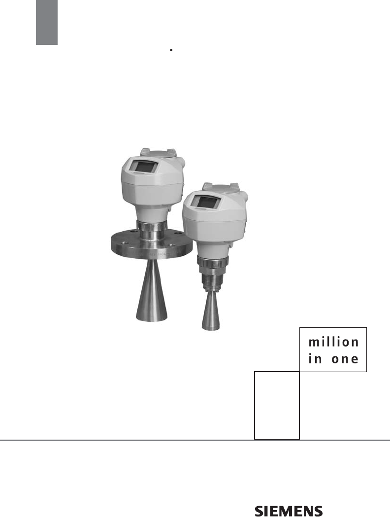
SITRANS LR250 Overview
SITRANS LR250 is a 2-wire 25 GHz pulse radar level transmitter for continuous monitoring
of liquids and slurries in storage vessels including high pressure and high temperature, to
a range of 20 meters (66 feet). It is ideal for small vessels and low dielectric media.
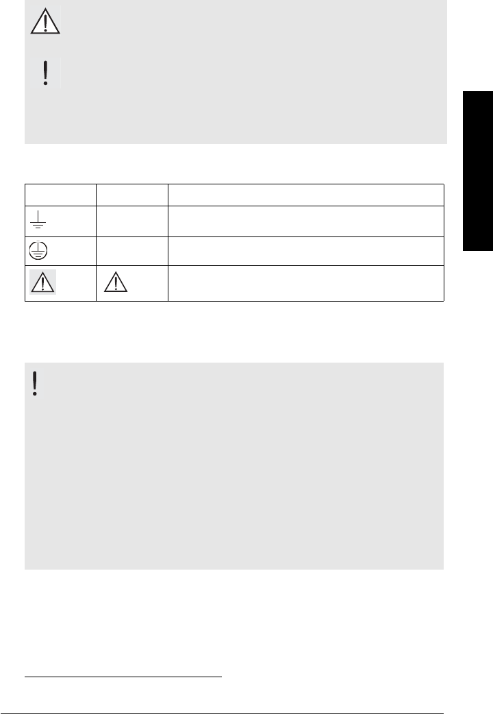
The instrument consists of an electronic component coupled to a horn antenna and either
a threaded or flange type process connection.
SITRANS LR250 supports HART1) communication protocol, and the following device
management software options:
• SIMATIC PDM
• AMS Device Manager
Signals are processed using Process Intelligence which has been field-proven in over
1,000,000 applications worldwide (ultrasonic and radar).
Programming
SITRANS LR250 is very easy to install and configure via a graphical local user interface
(LUI). You can modify the built in parameters either locally via the Siemens infrared
handheld programmer, or from a remote location using one of the following options:
• SIMATIC PDM
• AMS Device Manager
Applications
• liquids and slurries
• bulk storage vessels
• simple process vessels
1) HART® is a registered trademark of the HART Communication Foundation

Page 6 SITRANS LR250 (HART) – INSTRUCTION MANUAL 7ML19985JE03
mmmmm
SITRANS LR250
Approvals and Certificates
SITRANS LR250 is available with General Purpose approval, or for hazardous areas. In all
cases, check the nameplate on your instrument, and confirm the approval rating.
Process Connections
A wide range of process connections and antenna options is available to suit virtually
any vessel configuration.
.
Note: For further details see
Approvals
on page 10.
Application
Type
LR250
Version Approval Rating Valid for: Wiring
Non-
hazardous
General
Purpose CSAUS/C, FM, CE N. America,
Europe
See
page 24
Hazardous
Intrinsically
Safe (barrier
required)
ATEX II 1 G, EEx ia IIC T4
ATEX II 1 tD, EEx tD A20 IP67 T90 oCEurope See
page 26
IECEx SIR 05.0031X, Ex ia IIC T4
Ex tD A20 IP67 T90 oCInternational
ANZEX Ex ia IIC T4 (Tamb = –40 to
+80 oC) IP67 Australia
FM/CSA: (barrier required)
Class I, Div. 1, Groups A, B, C, D
Class II, Div. 1, Groups E, F, G
Class III T4
US/Canada
BR-Ex ia IIC T4 IP67 Brazil
Non-incendive
FM/CSA:
Class I, Div. 2, Groups A, B, C, D T5
Class II/III
US/Canada See
page 28
Flameproof
ATEX II 1/2 G, Ex dmia IIC T4
ATEX II 1D, 1/2D, 2D, Ex tD A20 IP67 Txx oC
IECEx SIR 08.0107, Ex dmia IIC T4
tD A20 IP67 Txx oC
Europe See
page 28
Increased
Safety
ATEX II 1/2 G, Ex emia IIC T4
ATEX II 1D, 1/2D, 2D, Ex tD A20 IP67 Txx oC
IECEx SIR 08.0107, Ex emia IIC T4
tD A20 IP67 Txx oC
Europe See
page 29
Explosion-
proof
FM/CSA:
Class I, Div. 1, Groups A, B, C, D
Class II, Div. 1, Groups E, F, G
Class III T4
US/Canada See
page 29

7ML19985JE03 SITRANS LR250 (HART) – INSTRUCTION MANUAL Page 7
mmmmm
Specifications
Specifications
Power
• Maximum 30 V DC
• 4 to 20 mA
• Max. startup current see
Startup Behavior
on page 141
Performance
Reference operating conditions according to IEC 60770-1
• ambient temperature +15 to +25 °C (+59 to +77 °F)
• humidity 45% to 75% relative humidity
• ambient pressure 860 to 1060 mbar g (86000 to 106000 N/m2 g)
Measurement Accuracy (measured in accordance with IEC 60770-1)
• Maximum measured error = 5 mm (0.2") (including hysteresis and non-
repeatability)
Frequency K-band
Max. measurement range1) 20 m (65.6 ft) except for 1.5" horn which has 10 m
(32.8 ft)
Min. detectable distance 50 mm (1.97") from end of horn2)
Update time3) minimum 1 second, depending on settings for
Response Rate (2.4.1.) and LCD Fast Mode (4.9.)
Influence of ambient temperature < 0.003%/K (average over full temperature range,
referenced to maximum range)
Note: Siemens Milltronics makes every attempt to ensure the accuracy of these
specifications but reserves the right to change them at any time.
General Purpose
Non-incendive (FM/CSA US/Canada only)
Intrinsically Safe
Nominal 24 V DC at 550 Ohm
Flameproof
Increased Safety
Explosion-proof (FM/CSA US/Canada only)
Nominal 24 V DC at 250 Ohm
1) From sensor reference point: see
Dimensions
on page 12 and
Flanged Horn with
extension
on page 14.
2) Minimum range is horn length + 50 mm. See
Dimensions
on page 12.
3) Reference conditions: Response Rate (2.4.1.) set to FAST, LCD Fast Mode (4.9.)
set to ON.

Page 8 SITRANS LR250 (HART) – INSTRUCTION MANUAL 7ML19985JE03
mmmmm
Specifications
Dielectric constant of material measured
• dK > 1.6 (horn and application dependent1))
Memory:
• non-volatile EEPROM
• no battery required.
Interface
Analog output
• signal range 4 to 20 mA (± 0.02 mA accuracy)
upper limit 20 to 23 mA adjustable
• fail signal 3.6 mA to 23 mA (see
Fail-safe Mode
on page 134 for
more details)
Communication: HART
• Load 230 to 600 Ω, 230 to 500 Ω when connecting a coupling
module
• Max. Line Length multi-wire: ≤ 1500 m (4921 ft)
• Protocol HART, Version 5.1
Configuration
• remote Siemens SIMATIC PDM or AMS Device Manager (PC)
• local Siemens infrared handheld programmer, or HART
handheld communicator
Display (local)2) graphic LCD, with bar graph representing level
Mechanical
Process Connections:
• threaded connection 1.5” or 2" NPT (ASME B1.20.1), BSPT (EN 10226-1)3) or
G (BS EN ISO 228-1)
• flange connection (flat-face)
2", 3", 4" (ASME 150 lb, 300 lb)
50, 80, 100 mm (PN 16, PN 40)
50A, 80A, 100A (JIS 10K)
materials 316 L /1.4404 or 316 L /1.4435 stainless steel, optional
Alloy N06022/2.4602
• flange connection (raised face)
50, 80, 100 mm (PN 10/16, PN 25/40)
150 mm (PN 10/16,PN 25/40)
per EN 1092-1 B1
materials 1.4404 or 1.4435 stainless steel, optional Alloy N06022/
2.4602
1) For 1.5" (40 mm) horn the dK is limited to 3 unless a stillpipe is used.
2) Display quality will be degraded in temperatures below –25 °C (–13 °F) and above
+65 °C (+149 °F).
3) For use with 1.5" (40 mm) horn antennas only.

7ML19985JE03 SITRANS LR250 (HART) – INSTRUCTION MANUAL Page 9
mmmmm
Specifications
Antenna:
• horn standard 1.5" (40 mm), 2" (50 mm), 3" (80 mm), and
4" (100 mm) horn, optional 100 mm (4") horn extension
• materials 316L stainless steel with PTFE emitter
optional Alloy N06022/2.4602 (C-22) with PTFE emitter
Enclosure
• construction aluminum, polyester powder-coated
• conduit entry 2 x M20x1.5, or 2 x ½" NPT
• ingress protection Type 4X/NEMA 4X, Type 6/NEMA 6, IP 67, IP68 (see
note below)
Weight (excluding extensions)
• 1.5" threaded connection with 1.5" horn antenna approx. 5.1kg
(11.2 lb)
• 2" threaded connection with 2" horn antenna approx. 5.5 kg
(12.1 lb)
• DN 50/PN 16 or 2" 150 lb flat-face flange with 2" horn antenna approx. 8 kg
(17.6 lb)
• DN 100/PN 40 or 4" ASME 300 lb flat-face flange with 4" horn antennaapprox.
17.4 kg (38.3 lb)
• DN 50/PN 16 raised-face flange with 2" horn antenna approx. 6 kg
(13.2 lb)
• DN 100/PN 40 raised-face flange with 4" horn antenna approx.
11.3 kg (24.9 lb)
Environmental
• location indoor/ outdoor
• altitude 5000 m (16,404 ft) max.
• ambient temperature −40 to +80 °C (−40 to +176 °F)
• relative humidity suitable for outdoor
Type 4X/NEMA 4X, Type 6/NEMA 6, IP67, IP68
enclosure (see note above)
• installation category I
• pollution degree 4
Notes:
• Check
Approvals
on page 10, for the specific configuration you are about to use or
install.
• Use appropriate conduit seals to maintain IP or NEMA rating.

Page 10 SITRANS LR250 (HART) – INSTRUCTION MANUAL 7ML19985JE03
mmmmm
Specifications
Process
•temperature
1)
at process connection
- with FKM O-ring −40 to +200 °C (−40 to +392 °F)
- with FFKM O-ring −20 to +200 °C (−4 to +392 °F)
• pressure (vessel)1Refer to
Process Pressure/Temperature derating
curves
on page 136.
Approvals
• General CSAUS/C, FM, CE
• Radio Europe (R&TTE), FCC, Industry Canada
• Hazardous Intrinsically Safe2) (Europe) ATEX II 1G, EEx ia IIC T4
ATEX II 3G, Ex na II T4
ATEX II 1D, EEx tD A20 IP67 T90 °C
(International) IECEx SIR 05.0031X, Ex ia IIC T4,
EX tD A20 IP67 T90 °C
(US/Canada) FM/CSA: (barrier required)
Class I, Div. 1, Groups A, B, C, D
Class II, Div. 1, Groups E, F, G
Class III T4
(Brazil) BR-Ex ia IIC T4 IP67
Non-incendive3) (US/Canada) FM/CSA
Class I, Div. 2,
Groups A, B, C, D T5
1) The specifications apply to the standard horn only. The maximum temperature is
dependent on the process connection, antenna materials, and vessel pressure.
For more detail, or for other configurations, see
Maximum Process Temperature
Chart
on page 135, and
Process Pressure/Temperature derating curves
on page
136.
Note: The device nameplate lists the approvals that apply to your device.
2) See
Intrinsically Safe wiring
on page 26 for more details.
3) See
Non-incendive wiring (US/Canada only)
on page 28 for more details.

7ML19985JE03 SITRANS LR250 (HART) – INSTRUCTION MANUAL Page 11
mmmmm
Specifications
• Hazardous (continued)
Flameproof (Europe)1) ATEX II 1/2 G, Ex dmia IIC T4
ATEX II 1D, 1/2D, 2D, Ex tD A20 IP67 Txx oC
IECEx SIR 08.0107, Ex dmia IIC T4
tD A20 IP67 Txx oC
Increased Safety (Europe)2) ATEX II 1/2 G, Ex emia IIC T4
ATEX II 1D, 1/2D, 2D, Ex tD A20 IP67 Txx oC
IECEx SIR 08.0107, Ex emia IIC T4
tD A20 IP67 Txx oC
Explosion proof (US/Canada)3) FM/CSA: (barrier not required)
Class I, Div. 1, Groups A, B, C, D
Class II, Div. 1, Groups E, F, G
Class III T4
• Marine Lloyd’s Register of Shipping
ABS Type Approval
Programmer (infrared keypad)
Siemens Milltronics Infrared IS (Intrinsically Safe) Hand Programmer for hazardous and
all other locations.
• approval ATEX II 1 G, EEx ia IIC T4, certificate SIRA 01ATEX2147
FM/CSA: Class I, Div. 1, Groups A, B, C, D
• ambient temperature −20 to 40 °C (−5 to 104 °F)
• interface proprietary infrared pulse signal
• power 3 V lithium battery
• weight 150 g (0.3 lb)
• color black
• Part Number 7ML1930-1BK
1) See
Flameproof wiring
on page 28.
2) See
Increased safety wiring
on page 29.
3) See
Explosion-proof wiring (US/Canada only)
on page 29.
Notes:
• Battery is non-replaceable with a lifetime expectancy of 10 years in normal use.
• To estimate the lifetime expectancy, check the nameplate on the back for the serial
number. The first six numbers show the production date (mmddyy), for example,
serial number 032608101V.
Page 12 SITRANS LR250 (HART) – INSTRUCTION MANUAL 7ML19985JE03
mmmmm
Specifications
Dimensions
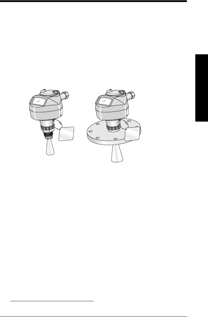
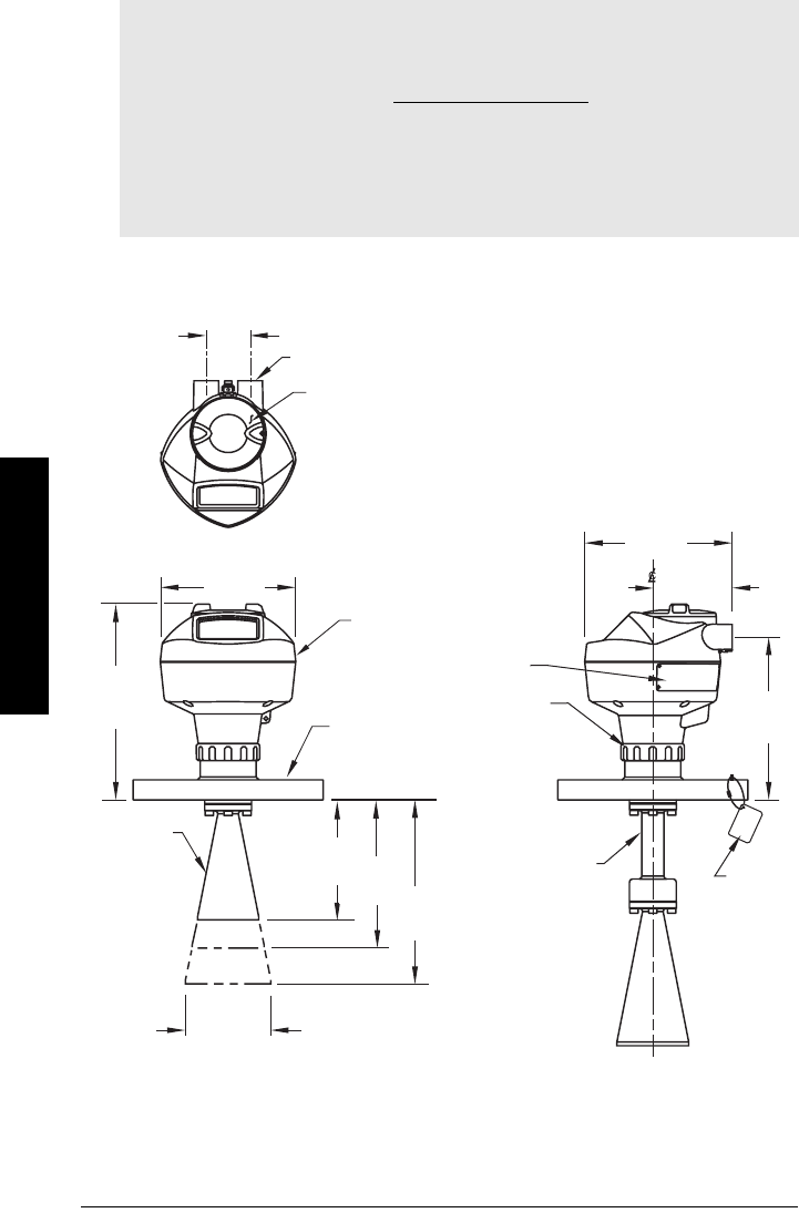
Threaded Horn Antenna with extension
See table under
Threaded Horn dimensions
on page 13 for horn height to sensor
reference point (A, B, C, or D).
Notes:
• Process temperature and pressure capabilities are dependent upon information on
the process device tag. Reference drawing listed on the Tag is available on the
product page of our website at www.siemens.com/LR250, under More Info/
Installation drawings/Level Measurement/Installation Drawings/LR250. Additional
information on process connections is available on the Installation Drawings page
under Process Connection Diagrams.
• Signal amplitude increases with horn diameter, so use the largest practical size.
• Optional extensions can be installed below the threads.
threaded cover
enclosure/
electronics
196 mm
(7.7")
154 mm
(6.1")
167 mm
(6.6")
1/2" NPT cable entry
(or alternatively, M20 cable gland)
sensor
ref.
point
retaining
collar
90 mm
(3.5")
159 mm
(6.26")
50 mm
(2.0")
horn
28 mm (1.1") optional
100 mm (4.0 ")
horn extension
process
device tag
horn
O.D.
A
B
C
D

7ML19985JE03 SITRANS LR250 (HART) – INSTRUCTION MANUAL Page 13
mmmmm
Specifications
Threaded Horn dimensions
Threaded Connection Markings
Threaded connection markings are found on the flat face/faces of the process
connection.
Serial number:a unique number allotted to each process connection, including the date of
manufacture (MMDDYY) followed by a number from 001 to 999.
Nominal Horn Size Horn O.D. Horn Height to sensor
reference pointa)
a) Height from bottom of horn to sensor reference point as shown: see
Threaded
Horn Antenna with extension
on page 12.
Beam Angleb)
b) – 3dB in the direction of the polarization axis (see
Polarization reference point
on page 22 for an illustration).
Measurement
Range
40 mm (1.5") 39.8 mm (1.57”) A135 mm (5.3") 19 degrees 10 m (32.8 ft)
50 mm (2”) 47.8 mm (1.88”) B166 mm (6.55”) 15 degrees
20 m (65.6 ft)80 mm (3”) 74.8 mm (2.94”) C199 mm (7.85”) 10 degrees
100 mm (4”) 94.8 mm (3.73”) D254 mm (10”) 8 degrees
Page 14 SITRANS LR250 (HART) – INSTRUCTION MANUAL 7ML19985JE03
mmmmm
Specifications
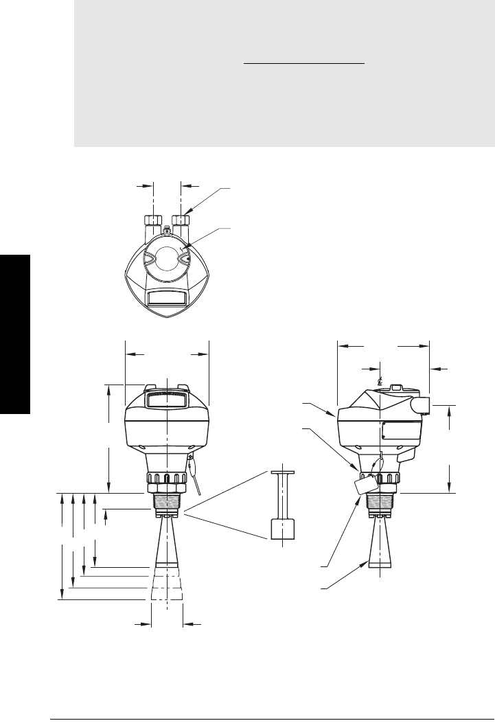
Flanged Horn with extension
Notes:
• Process temperature and pressure capabilities are dependent upon information on
the process device tag. Reference drawing listed on the Tag is available on the
product page of our website at www.siemens.com/LR250, under More Info/
Installation drawings/Level Measurement/Installation Drawings/LR250. Additional
information on process connections is available on the Installation Drawings page
under Process Connection Diagrams.
• Signal amplitude increases with horn diameter, so use the largest practical size.
• Optional extensions can be installed between the flange and the antenna.
enclosure/electronics
name-plate
flange
horn
sensor
reference
point
retaining collar
process
device
tag
227 mm
(8.94")
horn
O.D.
135.5 mm
(5.33")
154 mm
(6.1")
50 mm
(2.0")
threaded cover
1/2" NPT cable entry
(or alternatively, M20 cable gland)
168.5 mm
(6.63")
223.5mm
(8.8")
50 mm (2")
nom.
80 mm (3")
nom.
100 mm (4")
nom.
167 mm
(6.6")
90 mm
(3.5")
190 mm
(7.48")
optional
100 mm (4.0 ")
horn extension

7ML19985JE03 SITRANS LR250 (HART) – INSTRUCTION MANUAL Page 15
mmmmm
Specifications
Flanged Horn dimensions
For flange dimensions see
Raised-Face Flange per EN 1092-1
on page 16 or
Flat-Face
Flange
on page 17
Nominal Horn Size Horn O.D. Height to sensor
reference pointa)
a) Height from bottom of horn to sensor reference point as shown: see
Flanged
Horn dimensions
on page 15.
Beam Angleb)
b) – 3dB in the direction of the polarization axis (see
Polarization reference point
on page 22 for an illustration).
Measurement
Range
50 mm (2”) 47.8 mm (1.88”) 135.5 mm (5.33”) 15 degrees
20 m (65.6 ft)80 mm (3”) 74.8 mm (2.94”) 168.5 mm (6.63”) 10 degrees
100 mm (4”) 94.8 mm (3.73”) 223.5 mm (8.8”) 8 degrees
Page 16 SITRANS LR250 (HART) – INSTRUCTION MANUAL 7ML19985JE03
mmmmm
Specifications
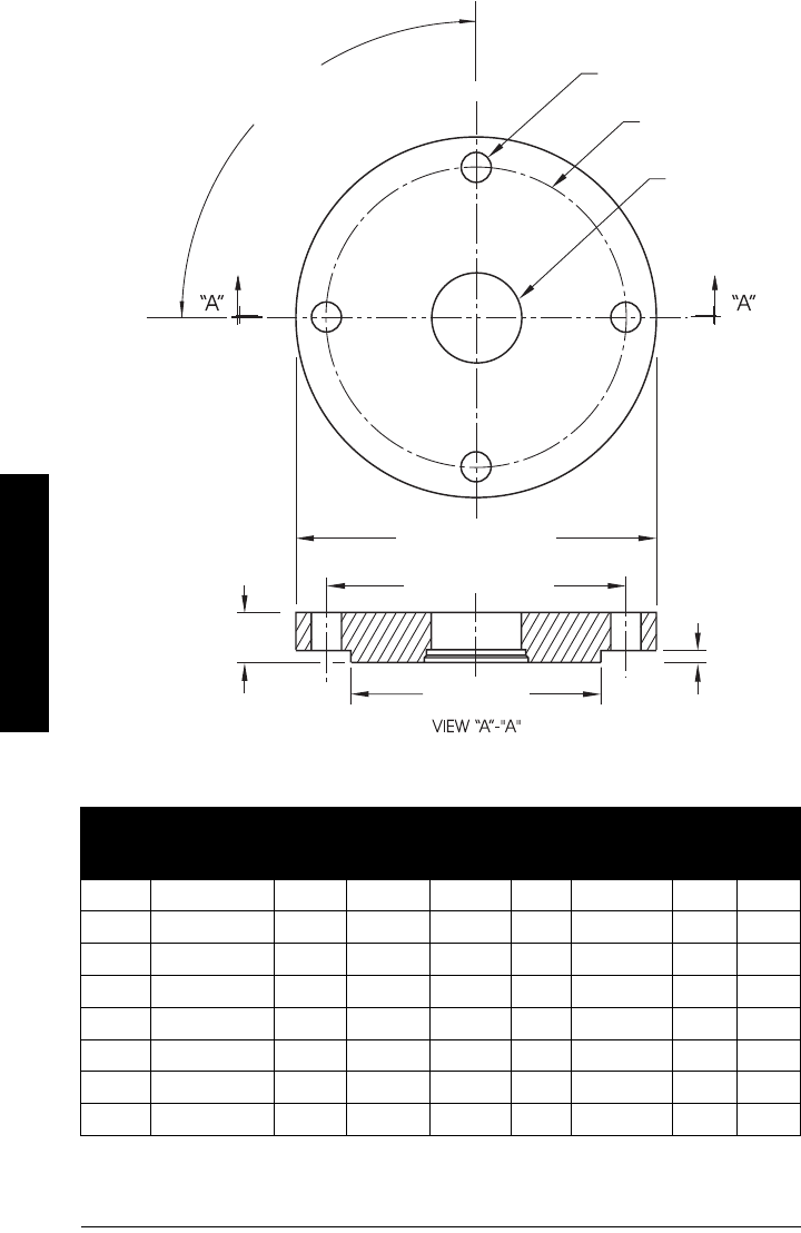
Raised-Face Flange per EN 1092-1
Raised-Face Flange Dimensions
Pipe
size
Flange
bolt hole
pattern
Flange
O.D.
(mm)
Bolt Hole
Circle Ø
(mm)
Bolt Hole
Ø (mm)
No. of
Bolts
Angle of
adjacent
bolt holes
Facing
Ø (mm)
Thick-
ness
(mm)
DN 50 PN 10/PN 16 165 125 18 4 90 102 18
DN 80 PN 10/PN 16 200 160 18 8 45 138 20
DN 100 PN 10/PN 16 220 180 18 8 45 158 20
DN 150 PN 10/PN 16 285 240 22 8 45 212 22
DN 50 PN 25/PN 40 165 160 18 4 90 138 20
DN 80 PN 25/PN 40 200 160 18 8 45 138 24
DN 100 PN 25/PN 40 235 190 22 8 45 162 24
DN 150 PN 25/PN 40 300 250 26 8 45 218 28
process side
waveguide
mounting hole
angle of adjacent bolt holes
flange O.D.
bolt hole circle
bolt hole circle dia.
thickness
Facing
height
= 3 mm
Facing dia.
bolt hole
7ML19985JE03 SITRANS LR250 (HART) – INSTRUCTION MANUAL Page 17
mmmmm
Specifications
Raised-Face Flange markings
The flange markings are located around the outside edge of the flange.
Serial number: a unique number allotted to each flange, including the date of
manufacture (MMDDYY) followed by a number from 001 to 999.
Flange series: the Siemens Milltronics drawing identification.
Heat code: a flange material batch code identification.
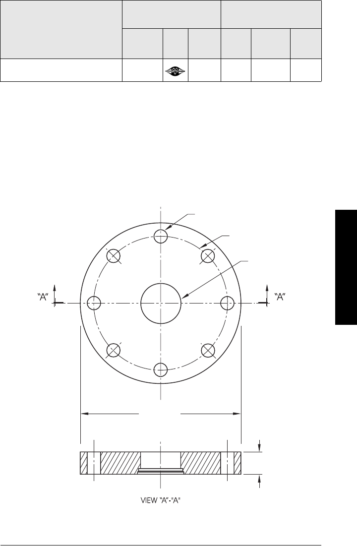
Flat-Face Flange
See
Flat-Face Flange Dimensions
on page 18 for details.
Blind Flange Markings
(Optional Manufacturer’s Logo
[optional]; Flange Standard;
Nominal Size; Material; Heat
Code)
Machining Identification Welded Assembly
Identificationa)
a) When flange material is Alloy N06022/2.4602, additional material and heat code
identification is provided.
Serial no. Logo Flange
series
Flange
series
Heat
Code no. Facing
Manufacturer’s logo; EN 1092-1 05 ’B1’;
’DN50’ ’PN16’ ’1.4404 or 1.4435’ A1B2C3 mmddyyxxx XXXXX XXXXX A1B2C3 RF
process side
enclosure
mounting hole
bolt hole
flange O.D.
bolt hole circle
thickness
Page 18 SITRANS LR250 (HART) – INSTRUCTION MANUAL 7ML19985JE03
mmmmm
Specifications
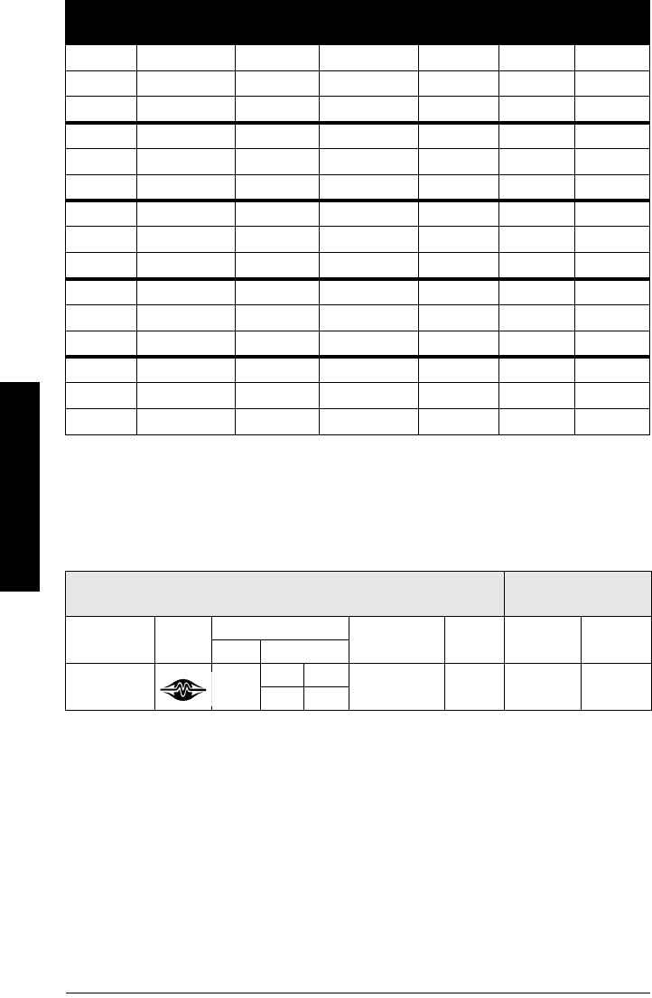
Flat-Face Flange Dimensions
Flat-Face Flange markings
Flange markings located around the outside edge of the flat-face flange identify the flange
assembly on which the device is mounted.
Serial number: a unique number allotted to each flange, including the date of manufacture
(MMDDYY) followed by a number from 001 to 999.
Flange series: the Siemens Milltronics drawing identification.
Nominal size: the flange size followed by the hole pattern for a particular flange class. For
example,
– a 2 inch ANSI B 16.5 150 lb class flange (North America)
– a DN 80 EN 1092-1 PN 16 class flange (Europe).
Material: the basic flange material (AISI or EU material designation). North American
material codes are followed by European ones. For example, material
designation 316L/1.4404.
Heat code: a flange material batch code identification.
Flange
sizea)
a) A 2" flange is designed to fit a 2" pipe: for actual flange dimensions see Flange O.D.
Flange Class Flange O.D. Bolt Hole
Circle Ø
Bolt Hole
Ø
No. of
Bolt Holes Thickness
2” ASME 150 lb 6.0” 4.75” 0.75” 4 0.88"
3” ASME 150 lb 7.5” 6.0” 0.75” 4 0.96"
4” ASME 150 lb 9.0” 7.50” 0.75” 8 1.25"
2” ASME 300 lb 6.50” 5.00” 0.75” 8 1.12"
3” ASME 300 lb 8.25” 6.62” 0.88” 8 1.38"
4” ASME 300 lb 10.00” 7.88” 0.88” 8 1.50"
DN 50 EN PN 16 165 mm 125 mm 18 mm 4 24.4 mm
DN 80 EN PN 16 200 mm 160 mm 18 mm 8 31.8 mm
DN 100 EN PN 16 220 mm 180 mm 18 mm 8 31.8 mm
DN 50 EN PN 40 165 mm 125 mm 18 mm 4 25.4 mm
DN 80 EN PN 40 200 mm 160 mm 18 mm 8 31.8 mm
DN 100 EN PN 40 235 mm 190 mm 22 mm 8 38.1 mm
50A JIS 10K 155 mm 120 mm 19 mm 4 23.8 mm
80A JIS 10K 185 mm 150 mm 19 mm 8 24.4 mm
100A JIS 10K 210 mm 175 mm 19 mm 8 28.5 mm
Flat Face Flange Identification Welded Assembly
Identification
Serial No. Logo Flange Series Material Heat
Code
Flange
Series
Heat Code
No.
Series Nominal Size
MMDDYYXXX 25556 2 150 316L/ 1.4404 or
316L/ 1.4435 A1B2C3 25546 A1B2C3
DN 80 PN 16

7ML19985JE03 SITRANS LR250 (HART) – INSTRUCTION MANUAL Page 19
mmmmm
Specifications
Notes

Page 20 SITRANS LR250 (HART) – INSTRUCTION MANUAL 7ML19985JE03
mmmmm
Installation
Installation
1)
WARNINGS:
• Installation shall only be performed by qualified personnel and in
accordance with local governing regulations.
• SITRANS LR250 is to be used only in the manner outlined in this manual,
otherwise protection provided by the device may be impaired.
• Handle the device using the enclosure not the device tag, to avoid
damage.
• Never attempt to loosen, remove, or disassemble process connection
or instrument housing while vessel contents are under pressure.
• This product is designated as a Pressure Accessory per Directive
97/23/EC and is not intended for use as a safety device.
• Materials of construction are chosen based on their chemical
compatibility (or inertness) for general purposes. For exposure to
specific environments, check with chemical compatibility charts
before installing.
• The user is responsible for the selection of bolting and gasket materials
which will fall within the limits of the flange and its intended use and
which are suitable for the service conditions.
• Improper installation may result in loss of process pressure.
Notes:
• For European Union and member countries, installation must be according to ETSI
EN 302372.
• Refer to the device nameplate for approval information.
• The Process Device Tag shall remain with the process pressure boundary
assembly1. In the event the instrument package is replaced, the Process Device Tag
shall be transferred to the replacement unit.
• SITRANS LR250 units are hydrostatically tested, meeting or exceeding the
requirements of the ASME Boiler and Pressure Vessel Code and the European
Pressure Equipment Directive.
• The serial numbers stamped in each process connection body provide a unique
identification number indicating date of manufacture.
Example: MMDDYY – XXX (where MM = month, DD = day, YY = year, and
XXX= sequential unit produced)
Further markings (space permitting) indicate flange configuration, size, pressure
class, material, and material heat code.
1) The process pressure boundary assembly comprises the components that act as a
barrier against pressure loss from the process vessel: that is, the combination of
process connection body and emitter, but normally excluding the electrical enclosure.
7ML19985JE03 SITRANS LR250 (HART) – INSTRUCTION MANUAL Page 21
mmmmm
Installation
Mounting location
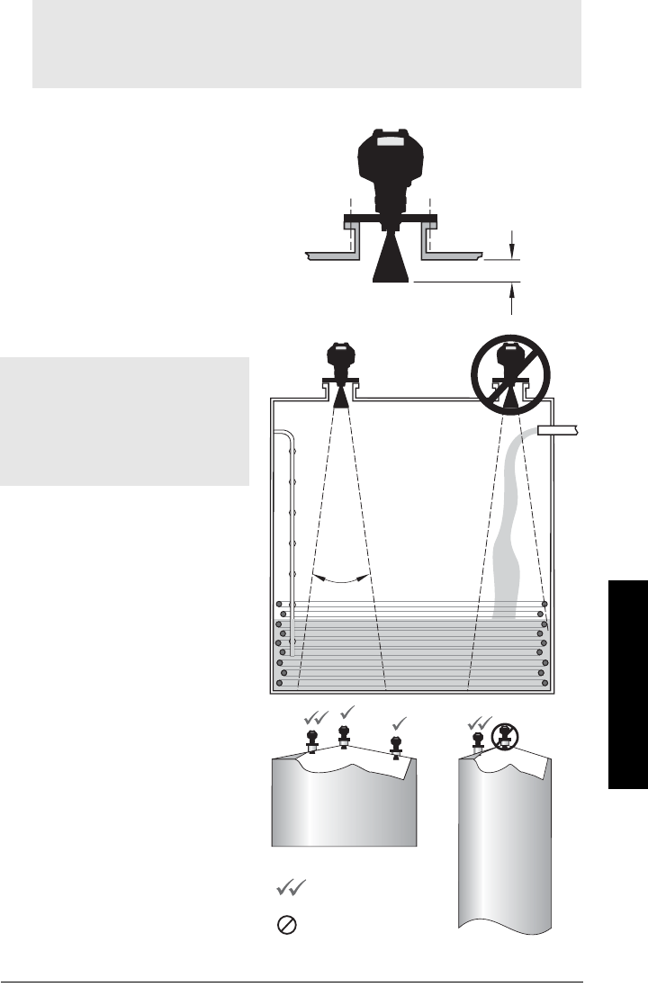
Nozzle design
• The end of the horn must protrude
a minimum of 10 mm (0.4”) to avoid
false echoes being reflected from
the nozzle.
• An antenna extension:
(100 mm/ 3.93") is available.
Nozzle location
• Keep emission cone free of
interference from ladders,
pipes, I-beams or filling
streams.
• Avoid central locations on
tall, narrow vessels.
Notes:
• Correct location is key to a successful application.
• Avoid reflective interference from vessel walls and obstructions by following the
guidelines below
Notes:
• Beam width depends on horn size:
see below.
• For details on avoiding false
echoes, see
Auto False Echo
Suppression (2.8.7.1.)
on page 130.
Min. clearance:
10 mm (0.4")
beam angle:
1.5" horn = 19°
2" horn = 15°
3" horn = 10°
4" horn = 8°
preferred
undesirable
19°
emission
cone
Page 22 SITRANS LR250 (HART) – INSTRUCTION MANUAL 7ML19985JE03
mmmmm
Installation
Nozzle location (continued)
• Provide easy access for viewing
the display and programming via
the hand programmer.
• Provide an environment suitable
to the housing rating and
materials of construction.
• Provide a sunshield if the
instrument will be mounted in
direct sunlight.
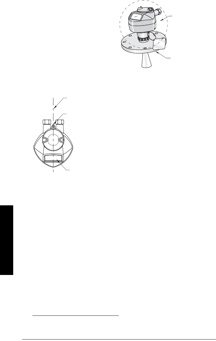
Orientation in a vessel with obstructions
Polarization reference point
Mounting on a Stillpipe or Bypass Pipe
A stillpipe or bypass is used for products with a low dK1), or when vortex or extremely
turbulent conditions exist. It can also be used to provide optimum signal conditions on
foaming materials.
Stillpipe or Bypass Pipe requirements
• The pipe diameter must be matched with the horn size. Use the largest horn size
that will fit the stillpipe/bypass pipe (see
Threaded Horn dimensions
on page 13 or
Flanged Horn dimensions
on page 15).
• Suitable pipe diameters: 40 mm (1.5") to 100 mm (4”).
Not recommended: (152.4 mm/ 6" or 203.2 mm/ 8")
• One continuous length of metallic pipe is preferred, without joints2).
1) See
Dielectric constant of material measured
on page 8.
2) Bad joints create reflections.
ambient temperature
–40 °C to 80 °C
(–40 °F to 176 °F)
process temperature
with FKM O-ring:
–40 to +200 °C
(–40 to +392 °F)
with FFKM O-ring:
–20 to +200 °C
(–4 to +392 °F)
polarization reference point
polarization
axis
display
For best results on a vessel with obstructions, or a stillpipe with
openings, orient the front or back of the device toward the
obstructions (see
Device orientation
on page 23 for an
illustration).

7ML19985JE03 SITRANS LR250 (HART) – INSTRUCTION MANUAL Page 23
mmmmm
Installation
• Joints (if unavoidable) must be machined to ± 0.25 mm (± 0.010”) and must have a
welded connecting sleeve on the outside.
• Bypass vent required at the upper end of the bypass1)
Device orientation
Installation Instructions
Threaded Version
1. Before inserting the device into its mounting connection, check to ensure the
threads are matching, to avoid damaging them.
2. Simply screw the device into the process connection, and hand tighten, or use a
wrench. A torque of 40 N m (30 ft.lbs) is recommended
Flanged Version
See
Flanged Horn with extension
on page 14,
Raised-Face Flange per EN 1092-1
on page
16, and
Flat-Face Flange
on page 17, for dimensions.
1) To equalize pressure and keep the liquid level in the bypass constant with the liquid
level in the vessel.
WARNING: For pressure applications, it will be necessary to use PTFE
tape or other appropriate thread sealing compound, and to tighten the
process connection beyond hand-tight.
Note: There is no limit to the number of times a device can be rotated without damage.
optimum
diameter
80 mm (3”)
align front or
back of
device with
vents
align front or back of
device with stillpipe slots
vent
Stillpipe Installation
slots
B
ypass Installation
Page 24 SITRANS LR250 (HART) – INSTRUCTION MANUAL 7ML19985JE03
mmmmm
Wiring
Wiring
Power
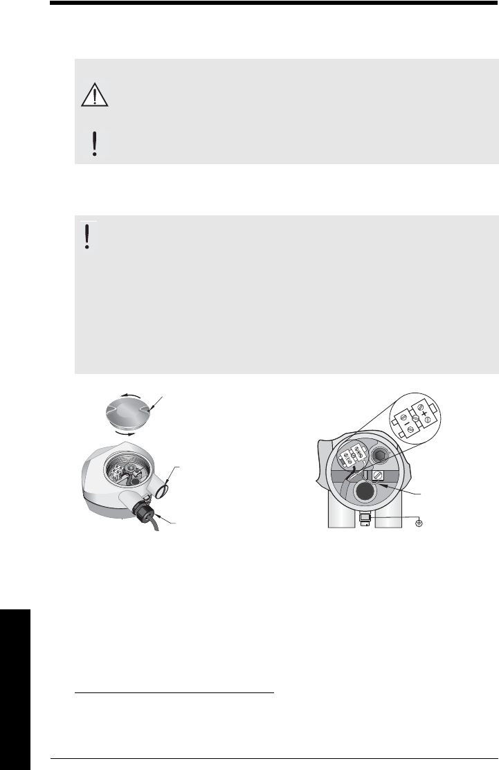
Connecting SITRANS LR250
1) 2)
1) Strip the cable jacket for approximately 70 mm (2.75") from the end of the cable, and
thread the wires through the gland2).
2) Connect the wires to the terminals as shown: the polarity is identified on the
terminal block.
3) Ground the instrument according to local regulations.
4) Tighten the gland to form a good seal.
WARNINGS:
The DC input terminals shall be supplied from a source providing
electrical isolation between the input and output, in order to meet
the applicable safety requirements of IEC 61010-1.
All field wiring must have insulation suitable for rated voltages.
WARNINGS:
• Check the nameplate on your instrument, to verify the approval rating.
• Use appropriate conduit seals to maintain IP or NEMA rating.
•See
Wiring setups for hazardous area installations
on page 25.
Notes:
• Use twisted pair cable: AWG 22 to 14 (0.34 mm2 to 2.5 mm2).
• Separate cables and conduits may be required to conform to standard
instrumentation wiring practices or electrical codes.
1) May be shipped with the device.
2) If cable is routed through conduit, use only approved suitable-size hubs for
waterproof applications.
Use a 2 mm Allen key to
loosen the lid-lock set
screw.
optional cable gland1) 2)
(or NPT cable entry2))
plug (IP 68)
cable shield
(if used)
7ML19985JE03 SITRANS LR250 (HART) – INSTRUCTION MANUAL Page 25
mmmmm
Wiring
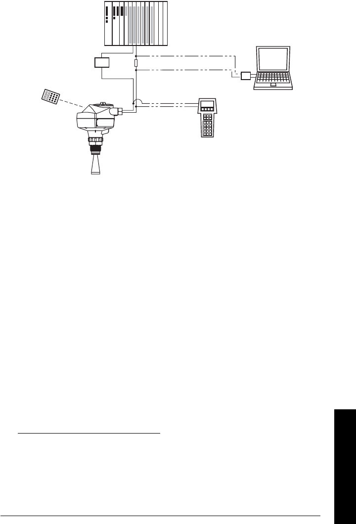
Connecting HART
1)2)
Wiring setups for hazardous area installations
There are five wiring options for hazardous area installations:
•
Intrinsically Safe wiring
on page 26
•
Non-incendive wiring (US/Canada only)
on page 28
•
Flameproof wiring
on page 28
•
Increased safety wiring
on page 29
•
Explosion-proof wiring (US/Canada only)
on page 29
In all cases, check the nameplate on your instrument, and confirm the approval rating.
1) Depending on the system design, the power supply may be separate from the
PLC, or integral to it.
2) HART resistance (total loop resistance, that is, cable resistance plus 250 Ohm
[resistor]) must be limited according to the allowable operating area as shown in
either
Curve 1 (General Purpose, Intrinsically Safe, Non-incendive)
on page 140
or
Curve 2 (Flameproof, Increased Safety, Explosion-proof)
on page 141.
active PLC
HART modem
SITRANS LR250
power supply (1)
Typical PLC/mA configuration with HART
R= 250 Ω (2)
HART
communicator
Page 26 SITRANS LR250 (HART) – INSTRUCTION MANUAL 7ML19985JE03
mmmmm
Wiring
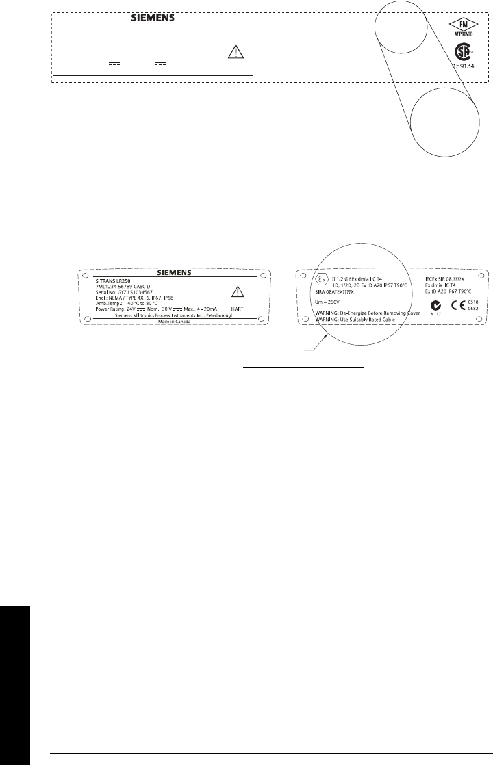
1. Intrinsically Safe wiring
• For power demands see
Curve 1 (General Purpose, Intrinsically Safe, Non-
incendive)
on page 140.
• For wiring requirements: follow local regulations.
• Approved dust-tight and water-tight conduit seals are required for outdoor
NEMA 4X / type 4X / NEMA 6, IP67, IP68 locations.
• Refer to
Instructions specific to hazardous area installations
on page 30.
• Recommended intrinsically safe barriers are listed under
Passive Shunt Diode
Barriers
on page 27 and
Active barriers (repeating barriers)
on page 27.
Note: Selecting a suitable PLC input module, power supply, or barrier requires
knowledge about Intrinsic Safety and the application. It is the responsibility of the
installer to ensure that the intrinsically safe installation complies with both the
apparatus approval requirements and the relevant national code of practice.
WARNING: Possible Static Hazard, Do Not Rub Or Clean On Site.
Ii = 120 mA
Ui = 30V
Li = 0.1mH
Pi = 0.8W
Ci = 15nF
HART
II1DIP68Txx
II 1 G EEx ia IIC T4
03ATEX2142X
IECEx SIR 05.0031X
Ex ia IIC T4
SIRA
SITRANS LR 250
Made in Canada
Siemens Milltronics Process Instruments Inc., Peterborough
7ML1234-56789-0ABC-D
Encl.: NEMA / TYPE 4X, 6, IP67, IP68
Amb.Temp.: – 40 °C to 80 °C
Power Rating: 24V Max., 4 - 20mA
Nom., 30 V
Serial No: GYZ / S1034567
The ATEX certificate listed on the nameplate can
be downloaded from the product page of our website at: www.siemens.com/LR250.
See also
ATEX Certificate SIRA 06ATEX2358X
on page 150
The IECEx certificate listed on the nameplate can be viewed on the IECEx website. Go to:
http://iecex.iec.ch and click on Ex Equipment Certificates of Conformity then enter the
certificate number IECEx SIR 05.0031X.
WARNING: Possible Static Hazard, Do Not Rub Or Clean On Site.
Exia per drawing: 23650653
Class I, Div1,Group A,B,C,D
Class III
Class II, Div1,Group G
CANADA: 267P - LR 250
HART
R
FCCID:NJA-LR250
Pmax = 0.8 W
Ci=15nF
Temp.Code:T4
Vmax = 30V
Li=0.1mH
Imax = 120mA
SITRANS LR 250
Made in Canada
Siemens Milltronics Process Instruments Inc., Peterborough
7ML1234-56789-0ABC-D
Encl.: NEMA / TYPE 4X, 6, IP67, IP68
Amb.Temp.: – 40 °C to 80 °C
Power Rating: 24V Max., 4 - 20mA
Nom., 30 V
Serial No: GYZ / S1034567
The FM/CSA Intrinsically Safe connection drawing
number 23650653 can be downloaded from
the product page of our website at: www.siemens.com/LR250.

7ML19985JE03 SITRANS LR250 (HART) – INSTRUCTION MANUAL Page 27
mmmmm
Wiring
Passive Shunt Diode Barriers
How to select a passive barrier for SITRANS LR250
To make sure that the barrier safety description is suitable for the LR250 Intrinsically Safe
(IS) input parameters, carry out the following calculations:
Re-e = max. end-to-end resistance of the barrier
Rloop = loop resistance (total of cable resistance plus any additional series
resistance, for example, PLC inputs and/or displays)
Vbarrier = value of any non-linear voltage drops due to the barrier
1) Determine the value for Re-e from the data sheet.
2) Calculate the total value for Rloop.
3) Calculate Rworking = Re-e + Rloop.
4) Determine the value of Vbarrier from the barrier data sheet (for example, voltage
drops due to diodes).
5) Calculate Vworking = Vsupply – Vbarrier.
Use the values for Vworking and Rworking to confirm that operation is within the
shaded area of the graph
Curve 1 (General Purpose, Intrinsically Safe, Non-incen-
dive)
on page 140.
Active barriers (repeating barriers)
Note: A well regulated supply voltage is required.
Manufacturer Part Number
MTL 787SP+ (Dual Channel)
MTL 7787P+ (Dual Channel)
Stahl 9001/01-280-100-10 (Single Channel)
Stahl 9002/01-280-110-10 (Dual Channel)
Manufacturer Part Number
MTL 706
MTL 7206
Siemens SITRANS I 7NG4122
Stahl 9001/51-280-110-14
MTL E02009
MTL E02010
Page 28 SITRANS LR250 (HART) – INSTRUCTION MANUAL 7ML19985JE03
mmmmm
Wiring
2. Non-incendive wiring (US/Canada only)
• For power demands see
Curve 1 (General Purpose, Intrinsically Safe, Non-
incendive)
on page 140.
3. Flameproof wiring
• For power demands see
Curve 2 (Flameproof, Increased Safety, Explosion-proof)
on
page 141.
• For wiring requirements follow local regulations.
• See also
Instructions specific to hazardous area installations
on page 30 and the
ATEX certificate listed above.
Class I, Div. 2,
Group A, B, C, D
Temp. Code: T5
This device complies with Part 15 of the FCC Rules.
Operation is subject to the following two conditions
1)This device may not cause harmful interference and
2)This device must accept any interference received,
including interference that may cause undesired operation
CANADA: 267P - LR 250
FCC ID: NJA - LR 250
26 Ghz HART
R
SITRANS LR 250
Made in Canada
Siemens Milltronics Process Instruments Inc., Peterborough
7ML1234-56789-0ABC-D
Encl.: NEMA / TYPE 4X, 6, IP67, IP68
Amb.Temp.: – 40 °C to 80 °C
Power Rating: 24V Max., 4 - 20mA
Nom., 30 V
Serial No: GYZ / S1034567
Class I, Div 2,
Group
A,B,C,D
FM/CSA Class 1, Div 2
connection drawing number 23650673
can be downloaded from the product page of our website at:
www.siemens.com/LR250.
The ATEX certificate can be downloaded from
the product page of our website at: www.siemens.com/LR250.
See also
ATEX Certificate SIRA 08ATEX1301X
on page 153
The IECEx certificate listed on the nameplate can be viewed on the IECEx website.
Go to: http://iecex.iec.ch and click on Ex Equipment Certificates of Conformity then
enter the certificate number IECEx SIR 08.0107X.
NAMEPLATE TO BE UPDATED
7ML19985JE03 SITRANS LR250 (HART) – INSTRUCTION MANUAL Page 29
mmmmm
Wiring
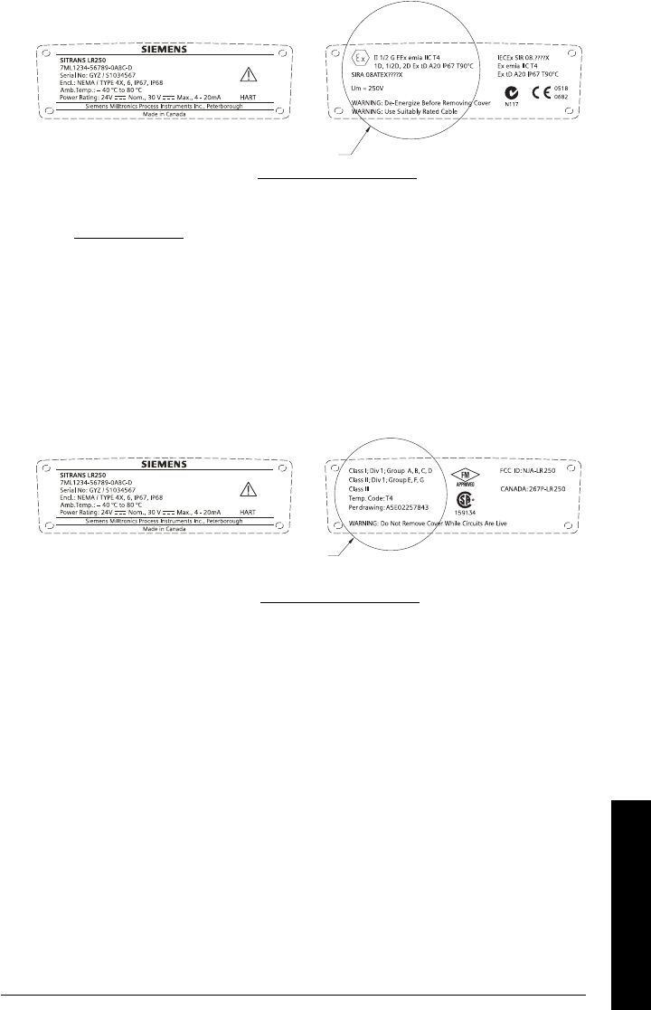
4. Increased safety wiring
• For power demands see
Curve 2 (Flameproof, Increased Safety, Explosion-proof)
on
page 141.
• For wiring requirements follow local regulations.
• See also
Instructions specific to hazardous area installations
on page 30 and the
ATEX certificate listed above.
5. Explosion-proof wiring (US/Canada only)
• For power demands see
Curve 2 (Flameproof, Increased Safety, Explosion-proof)
on
page 141.
The ATEX certificate can be downloaded from
the product page of our website at: www.siemens.com/LR250.
See also
ATEX Certificate SIRA 08ATEX1301X
on page 153
The IECEx certificate listed on the nameplate can be viewed on the IECEx website.
Go to: http://iecex.iec.ch and click on Ex Equipment Certificates of Conformity then
enter the certificate number IECEx SIR 08.0107X.
NAMEPLATE TO BE UPDATED
FM/CSA Explosion Proof connection drawing
number A5E02257843 can be downloaded from
the product page of our website at: www.siemens.com/LR250.
NAMEPLATE TO BE UPDATED

Page 30 SITRANS LR250 (HART) – INSTRUCTION MANUAL 7ML19985JE03
mmmmm
Wiring
Instructions specific to hazardous area
installations
(Reference European ATEX Directive 94/9/EC,
Annex II, 1/0/6)
The following instructions apply to equipment covered by certificate number
SIRA 06ATEX2358X and SIRA 08ATEX1301X.
1) For use and assembly, refer to the main instructions.
2) The equipment is certified for use as Category 1GD equipment.
3) The equipment may be used with flammable gases and vapors with apparatus group
IIC, IIB and IIA and temperature classes T1, T2, T3 and T4.
4) The equipment has a degree of ingress protection of IP67 and a temperature class
of T90°C and may be used with flammable dusts.
5) The equipment is certified for use in an ambient temperature range of –40 °C to
80 °C.
6) The equipment has not been assessed as a safety related device (as referred to by
Directive 94/9/EC Annex II, clause 1.5).
7) Installation and inspection of this equipment shall be carried out by suitably trained
personnel in accordance with the applicable code of practice (EN 60079-14 and
EN 60079-17 in Europe).
8) The equipment is non-repairable.
9) The certificate numbers have an ‘X’ suffix, which indicates that special conditions
for safe use apply. Those installing or inspecting this equipment must have access
to the certificates.
10) If the equipment is likely to come into contact with aggressive substances, then it is
the responsibility of the user to take suitable precautions that prevent it from being
adversely affected, thus ensuring that the type of protection is not compromised.
- Aggressive substances: for example, acidic liquids or gases that may attack
metals, or solvents that may affect polymeric materials.
- Suitable precautions: for example, establishing from the material’s data sheet
that it is resistant to specific chemicals.
7ML19985JE03 SITRANS LR250 (HART) – INSTRUCTION MANUAL Page 31
mmmmm
Quick Start: local
Operating via the handheld programmer
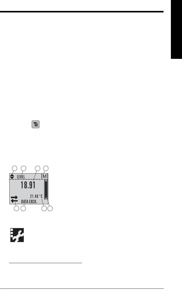
SITRANS LR250 carries out its level measurement tasks according to settings made via
parameters. The settings can be modified locally via the Local User Interface (LUI) which
consists of an LCD display and a handheld programmer.
A Quick Start Wizard provides an easy step-by-step procedure to configure the device for
a simple application. There are two ways to access the wizard:
• locally (see
Quick Start Wizard via the handheld programmer
on page 36)
• from a remote location (see
Quick Start Wizard via SIMATIC PDM
on page 41,
or
Quick Start Wizard via AMS Device Manager
on page 63
For more complex setups see
Appendix E: Application Examples
on page 142, and for the
complete range of parameters see
Parameter Reference
on page 78.
Activating SITRANS LR250
Power up the instrument. SITRANS LR250 automatically starts up in Measurement mode.
A transition screen showing the current firmware revision and an incrementing line of
stars is displayed while the first measurement is being processed.
Press Mode to toggle between Measurement and Program Mode.1) 2)
The LCD Display
Measurement mode display
Normal operation
Fault present
1) Press UP or DOWN arrow to switch.
2) In response to a key press request. For details, see
Key functions in Measurement
mode
on page 32.
1 – toggle indicator1) for linear units or %
2 – selected operation: level, space, distance, or volume
3 – measured value (level or volume, space, or distance)
4 – units
5 – bar graph indicates level
6 – secondary region indicates on request2) electronics
temperature, echo confidence, loop current, or distance
7 – text area displays status messages
8 – device status indicator (see
Device Status Icons
on page 118)
678
1342
5
S: 0 LOE
7 – text area displays a fault code and an error message
8 – service required icon appears
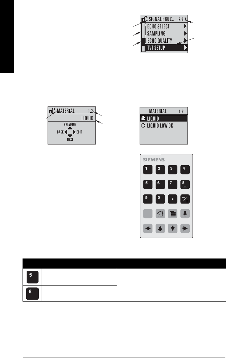
Page 32 SITRANS LR250 HART) – INSTRUCTION MANUAL 7ML19985JE03
mmmmm
Quick Start: local
PROGRAM mode display
Navigation view
• A visible menu bar indicates the
menu list is too long to display all
items.
• A band halfway down the menu
bar indicates the current item is
halfway down the list.
• The depth and relative position of the item band on the menu bar indicates the length of
the menu list, and approximate position of the current item in the list.
• A deeper band indicates fewer items.
Handheld Programmer
(Part No. 7ML1930-1BK)
The programmer is ordered separately.
Key functions in Measurement mode
Key Function Result
Updates the loop current.
New value is displayed in LCD secondary region.
Updates internal enclosure tem-
perature reading.
current
item
number
current
item
current
menu
item
band
menu
bar
parameter
value/
selection
parameter
number
parameter
name
Edit viewParameter view
C
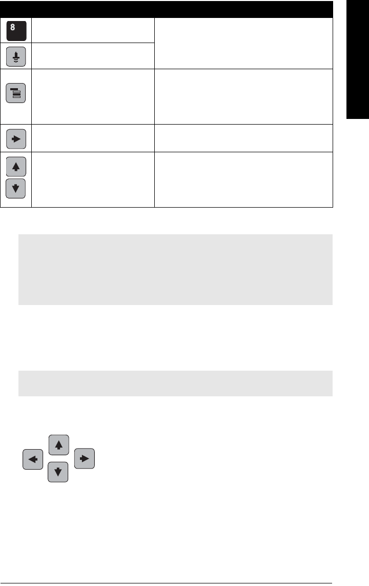
7ML19985JE03 SITRANS LR250 (HART) – INSTRUCTION MANUAL Page 33
mmmmm
Quick Start: local
Programming SITRANS LR250
Change parameter settings and set operating conditions to suit your specific application.
(For remote operation see
Operating via SIMATIC PDM
on page 40 or
Operating via AMS
Device Manager
on page 60.)
Parameter menus
Parameters are identified by name and organized into function groups (see
LCD menu
structure
on page 165).
Updates echo confidence value.
New value is displayed in LCD secondary region.
Updates distance measurement.
Mode opens PROGRAM mode.
Opens the menu level last displayed in this power
cycle, unless power has been cycled since exit-
ing PROGRAM mode or more than 10 minutes
have elapsed since PROGRAM mode was used.
Then top level menu will be displayed.
RIGHT arrow
opens PROGRAM mode. Opens the top level menu.
UP or DOWN arrow
toggles between linear units and
percent.
LCD displays measured value in either linear
units or percent.
Notes:
• While the device is in PROGRAM mode the output remains fixed and does not
respond to changes in the device.
• SITRANS LR250 automatically returns to Measurement mode after a period of
inactivity in PROGRAM mode (between 15 seconds and 10 minutes, depending on
the menu level).
Note: For the complete list of parameters with instructions, see
Parameter Reference
on page 78.
Key Function Result (cont’d)
1. QUICK START
2. SETUP
2.1. DEVICE
.............
2.7. LINEARIZATION
2.7.1. VOLUME
2.7.1.1. VESSEL SHAPE
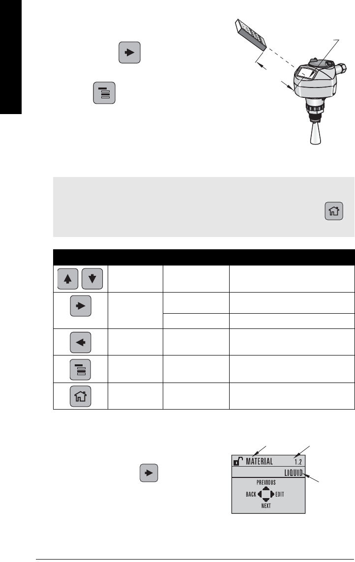
Page 34 SITRANS LR250 HART) – INSTRUCTION MANUAL 7ML19985JE03
mmmmm
Quick Start: local
1. Enter PROGRAM mode
• Point the programmer at the display from a
maximum distance of 300 mm (1 ft).
•RIGHT arrow activates PROGRAM
mode and opens menu level 1.
•Mode opens the menu level last
displayed in PROGRAM mode within the last
10 minutes, or menu level 1 if power has
been cycled since then.
2. Navigating: key functions in Navigation mode
3. Editing in PROGRAM mode
Selecting a listed option
a) Navigate to the desired parameter.
b) Press RIGHT arrow to open parameter
view.
Notes:
• In Navigation mode ARROW keys move to the next menu item in the direction of the
arrow.
• For Quick Access to parameters via the handheld programmer, press Home ,
then enter the menu number, for example: 2.7.1 (Volume).
Key Name Menu level Function
UP or DOWN
arrow menu or parameter Scroll to previous or next menu or
parameter.
RIGHT arrow menu Go to first parameter in the selected
menu, or open next menu.
parameter Open Edit mode.
LEFT arrow menu or parameter Open parent menu.
Mode menu or parameter Change to MEASUREMENT mode.
Home menu or parameter Open top level menu: menu 1.
display
handheld programmer
Max. 300 mm
(1 ft)
parameter name parameter
number
current
selection
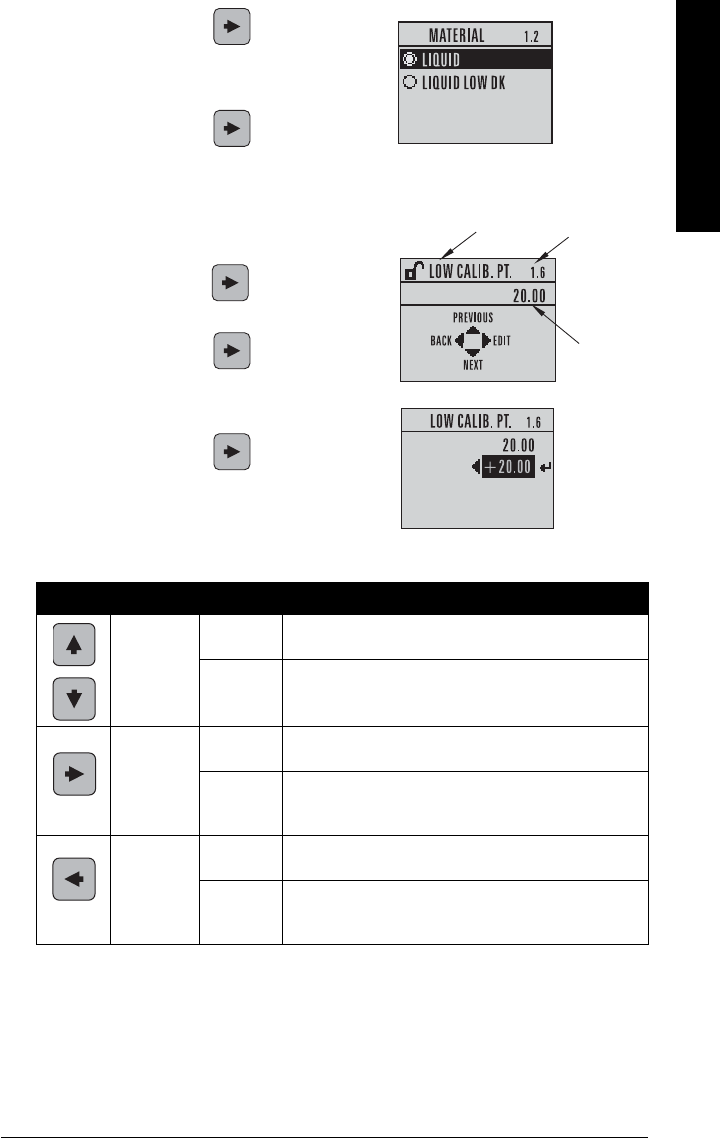
7ML19985JE03 SITRANS LR250 (HART) – INSTRUCTION MANUAL Page 35
mmmmm
Quick Start: local
c) Press RIGHT arrow again to open Edit
mode. The current selection is highlighted.
Scroll to a new selection.
d) Press RIGHT arrow to accept it
The LCD returns to parameter view and
displays the new selection.
Changing a numeric value
a) Navigate to the desired parameter.
b) Press RIGHT arrow to open parameter
view. The current value is displayed.
c) Press RIGHT arrow again to open Edit
mode. The current value is highlighted.
d) Key in a new value.
e) Press RIGHT arrow to accept it. The
LCD returns to parameter view and displays
the new selection.
Key functions in Edit mode
Key Name Function
UP or
DOWN
arrow
Selecting
options Scrolls to item.
Numeric
editing
- Increments or decrements digits
- Toggles plus and minus sign
RIGHT
arrow
Selecting
options
- Accepts the data (writes the parameter)
- Changes from Edit to Navigation mode
Numeric
editing
- Moves cursor one space to the right
- or with cursor on Enter sign, accepts the data and
changes from Edit to Navigation mode
LEFT
arrow:
Selecting
options Cancels Edit mode without changing the parameter
Numeric
editing
- Moves cursor to plus/minus sign if this is the first key
pressed
- or moves cursor one space to the left.
current
value
parameter
number
parameter name
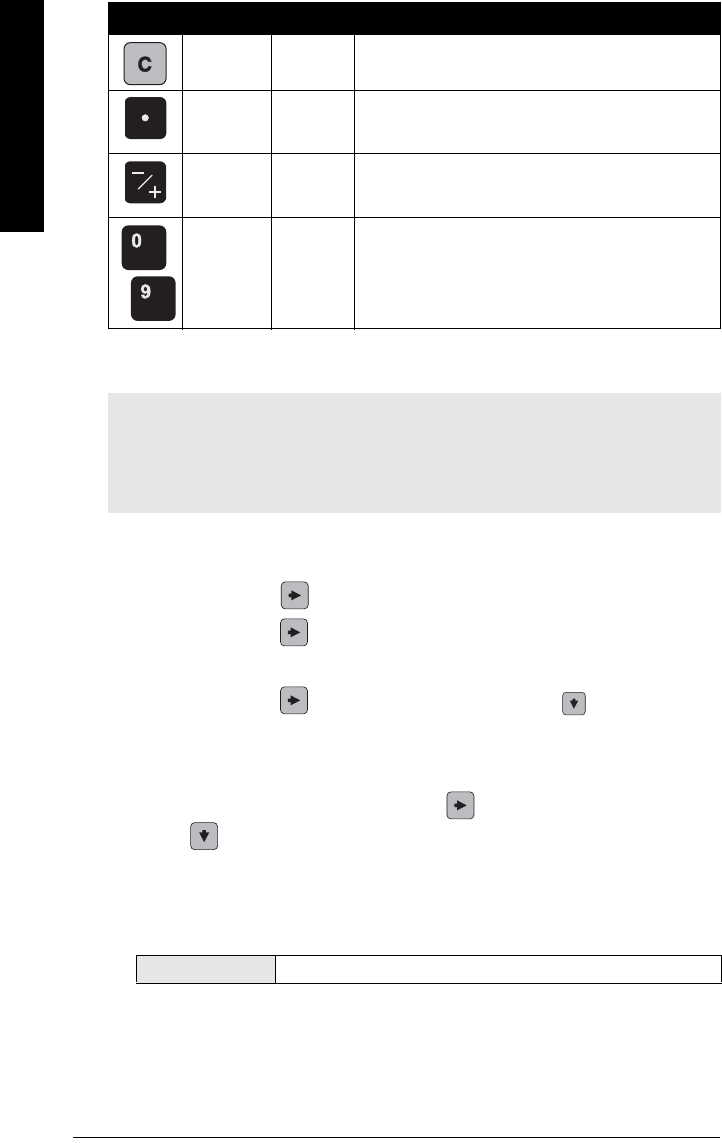
Page 36 SITRANS LR250 HART) – INSTRUCTION MANUAL 7ML19985JE03
mmmmm
Quick Start: local
Quick Start Wizard via the handheld programmer
1. Quick Start
a) Point the programmer at the display from a maximum distance of 300 mm (1 ft), then
press RIGHT arrow to activate PROGRAM mode and open menu level 1.
b) Press RIGHT arrow twice to navigate to menu item 1.1 and open parameter
view.
c) Press RIGHT arrow to open Edit mode or DOWN arrow to accept default
values and move directly to the next item.
d) To change a setting, scroll to the desired item or key in a new value.
e) After modifying a value, press RIGHT arrow to accept it and press DOWN
arrow to move to the next item.
f) Quick Start settings take effect only after you select Yes to Apply changes in step 1.8.
1.1. Language
Selects the language to be used on the LCD and takes effect immediately.
Clear Numeric
editing Erases the display.
Decimal
point
Numeric
editing Enters a decimal point.
Plus or
minus
sign
Numeric
editing Changes the sign of the entered value.
to
Numeral Numeric
editing Enters the corresponding character.
Notes:
• The Quick Start wizard settings are inter-related and changes apply only after you
select YES in Apply? (Apply changes) (1.8.).
• Do not use the Quick Start wizard to modify individual parameters: see instead
Parameter Reference
on page 78.
Options English, Deutsch, Français, Español
Key Name Function (cont’d)
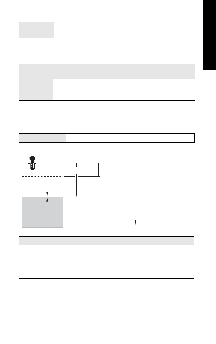
7ML19985JE03 SITRANS LR250 (HART) – INSTRUCTION MANUAL Page 37
mmmmm
Quick Start: local
1.2. Material
Selects the appropriate echo processing algorithms for the material (see Position
Detect (2.8.4.2.) on page 127 for more detail).
1.3. Response Rate
Sets the reaction speed of the device to measurement changes in the target range.
Use a setting just faster than the maximum filling or emptying rate (whichever is
greater).
1.4. Units
Sensor measurement units.
1.5. Operation Mode
1)
Options LIQUID
LIQUID LOW DKa) (low dielectric liquid – CLEF
algorithm enabled
)
a) dK < 3.0
Options
Response
Rate (1.3.) Fill Rate (2.4.2.)/Empty rate (2.4.3.)
SLOW 0.1 m/min (0.32 ft/min)
MED 1.0 m/min (3.28 ft/min)
FAST 10.0 m/min (32.8 ft/min)
Options M, CM, MM, FT, IN
Operation Description Reference point
NO
SERVICE
Measurement and associated loop cur-
rent are not updated, and the device
defaults to Fail-safe modea).
a) See Material Level (2.5.1.) on page 83 for more detail.
LEVEL Distance to material surface Low Calibration Point
SPACE Distance to material surface High Calibration Point
DISTANCE Distance to material surface Sensor Reference Point
1) The point from which High and Low Calibration points are referenced: see
Dimensions
on page 12 and
Flanged Horn with extension
on page 14.
High Cal. Point
(process full
level)
Low Cal. Point
(process empty level)
Level
Space
Distance
sensor reference point1)
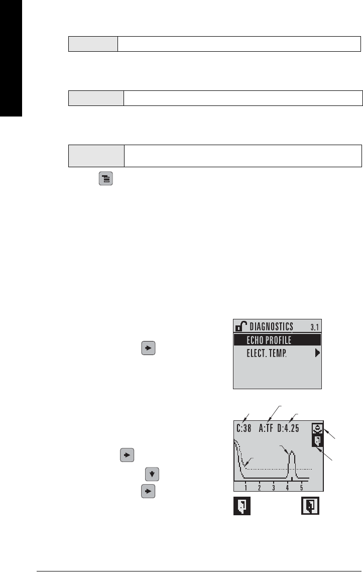
Page 38 SITRANS LR250 HART) – INSTRUCTION MANUAL 7ML19985JE03
mmmmm
Quick Start: local
1.6. Low Calibration Point
Distance from Sensor Reference to Low Calibration Point: usually process empty
level. (See Operation Mode (1.5.) for an illustration.)
1.7. High Calibration Point
Distance from Sensor Reference to High Calibration Point: usually process full level.
(See Operation Mode (1.5.) for an illustration.)
1.8. Apply? (Apply changes)
In order to save the Quick Start settings it is necessary to select Yes to apply
changes.
Press Mode to return to Measurement mode. SITRANS LR250 is now ready to
operate.
Auto False Echo Suppression
If you have a vessel with known obstructions, we recommend using Auto False Echo
Suppression to prevent false echo detection. See TVT setup (2.8.7.) on page 94 for
instructions.
This feature can also be used if SITRANS LR250 displays a false high level, or the reading
is fluctuating between the correct level and a false high level.
Requesting an Echo Profile
• In PROGRAM mode, navigate to: Level
Meter > Diagnostics (3.) > Echo Profile (3.1.)
• Press RIGHT arrow to request a profile.
•UP/DOWN arrows are dedicated to scrolling
through the icons.
• The selected icon is highlighted.
• Press UP arrow to select Measure and
RIGHT arrow to update the profile.
• Press DOWN arrow to select Exit then
press RIGHT arrow to return to the
previous menu.
Values Range: 0.00 to 20.00 m
Values Range: 0.00 to 20.00 m
Options YES, NO, DONE (Display shows DONE when Quick Start is successfully com-
pleted.)
algorithm: tF
confidence
distance
TVT
echo
exit icon
selected /
highlighted
exit icon
deselected
exit
measure
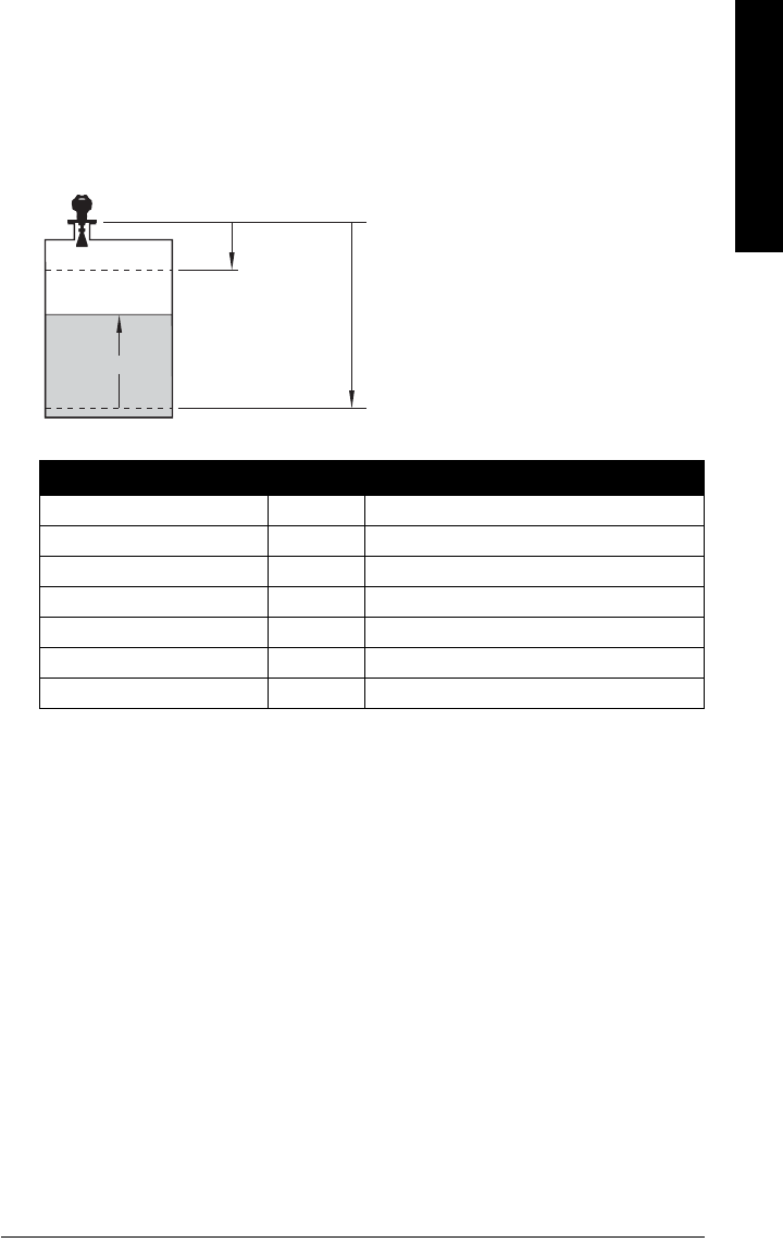
7ML19985JE03 SITRANS LR250 (HART) – INSTRUCTION MANUAL Page 39
mmmmm
Quick Start: local
Level application example
The application is a vessel that takes an average 3 hours (180 minutes) to fill and 3 weeks
to empty.
Fill rate = 0.08 m/minute [(Low Cal Pt. minus High Cal Pt.) / fastest of fill or empty time]
= (15.5 m – 1 m) / 180 min.
= 14.5 m /180 min. = 0.08 m/min.
Quick Start Parameter Setting Description
Material (1.2.) LIQUID
Response Rate (1.3.) SLOW Resets Fill Rate and Empty Rate to 0.1 m/minute.
Units (1.4.) m
Operation Mode (1.5.) LEVEL Material level referenced from Low Cal. Point.
Low Calibration Point (1.6.) 15.5 Process empty level.
High Calibration Point (1.7.) 1.0 Process full level.
Apply? (Apply changes) (1.8.) YES Save new settings.
sensor
reference
point
Level
Low Cal.
Point
High Cal.
Point
15.5 m
1.0 m
SITRANS LR250

Page 40 SITRANS LR250 (HART) – INSTRUCTION MANUAL 7ML19985JE03
mmmmm
SIMATIC PDM
Operating via SIMATIC PDM
SIMATIC PDM is a software package used to commission and maintain SITRANS LR250 and
other process devices. Please consult the operating instructions or online help for details on
using SIMATIC PDM. (You can find more information at www.siemens.com/simatic-pdm.)
Functions in SIMATIC PDM
SIMATIC PDM monitors the process values, alarms and status signals of the device. It allows
you to display, compare, adjust, verify, and simulate process device data; also to set schedules
for calibration and maintenance.
Parameters are identified by name and organized into function groups. See
LCD menu
structure
on page 165 for a chart1) and
Changing parameter settings using SIMATIC
PDM
on page 48 for more details.
See
Parameters accessed via pull-down menus
on page 48 for parameters that do not
appear in the menu structure in SIMATIC PDM.
Features of SIMATIC PDM Rev. 6.0, SP4
The graphic interface in SITRANS LR250 makes monitoring and adjustments easy.
Notes:
• For a complete list of parameters see
Parameter Reference
on page 78.
• While the device is in PROGRAM mode the output remains fixed and does not
respond to changes in the device.
1) The menu structure for SIMATIC PDM is almost identical to that for the LCD.
Feature page Function
Quick Start 42 Device configuration for simple applications
Echo Profile Utilities 49
Easy access to echo profile viewing/comparison,
TVT shaping, auto false echo suppression and
echo setup
Auto False Echo Suppression 52 Screen out false echoes
TVT Shaper 51 Manual TVT adjustment
Linearization 45 Volume measurement in an irregular vessel
Process Variables 57 Monitor process variables and level trend
Security 58 Protect security and communication parameters
from modification by the maintenance user

7ML19985JE03 SITRANS LR250 (HART) – INSTRUCTION MANUAL Page 41
mmmmm
SIMATIC PDM
Features of SIMATIC PDM Rev. 5.2, SP1
SIMATIC PDM Rev. 5.2 SP1 is supported only for basic configuration and troubleshooting. For
advanced features such as the Quick Start wizard, Rev. 6.0 SP3 HF2 or higher is required.
Electronic Device Description (EDD)
You can locate the EDD in Device Catalog, under Sensors/Level/Echo/Siemens Milltronics/
SITRANS LR250. Check the product page of our website at: www.siemens.com/LR250, under
Downloads, to make sure you have the latest version of SIMATIC PDM, the most recent
Service Pack (SP) and the most recent hot fix (HF). If you need to install a new EDD see
Configuring a new device
below.
Configuring a new device
1) Check that you have the most recent EDD, and if necessary download it from the
product page of our website at www.siemens.com/LR250. Save the files to your
computer, and extract the zipped file to an easily accessed location. Launch SIMATIC
PDM – Manager Device Catalog, browse to the unzipped EDD file and select it.
2) Launch SIMATIC Manager and create a new project for LR250. Application Guides
for setting up HART devices with SIMATIC PDM can be downloaded from the
product page of our website at: www.siemens.com/LR250.
3) Open the menu Device – Master Reset and click on OK to perform a reset to Factory
Defaults.
4) After the reset is complete upload parameters to the PC/PG.
5) Configure the device via the Quick Start wizard.
Quick Start Wizard via SIMATIC PDM
The graphic Quick Start Wizard provides an easy 5-step procedure that configures the
device for a simple application.
Please consult the operating instructions or online help for details on using
SIMATIC PDM.
1) If you have not already done so, check that you have the most up-to-date Electronic
Device Description (EDD) for your instrument. (See
Configuring a new device
above.)
2) Launch SIMATIC Manager and create a new project for LR250. (Application Guides
for setting up HART and PROFIBUS PA devices with SIMATIC PDM can be
downloaded from the product page of our website at: www.siemens.com/LR250).
Note: Clicking on Cancel during an upload from device to SIMATIC PDM will result in
some parameters being updated.
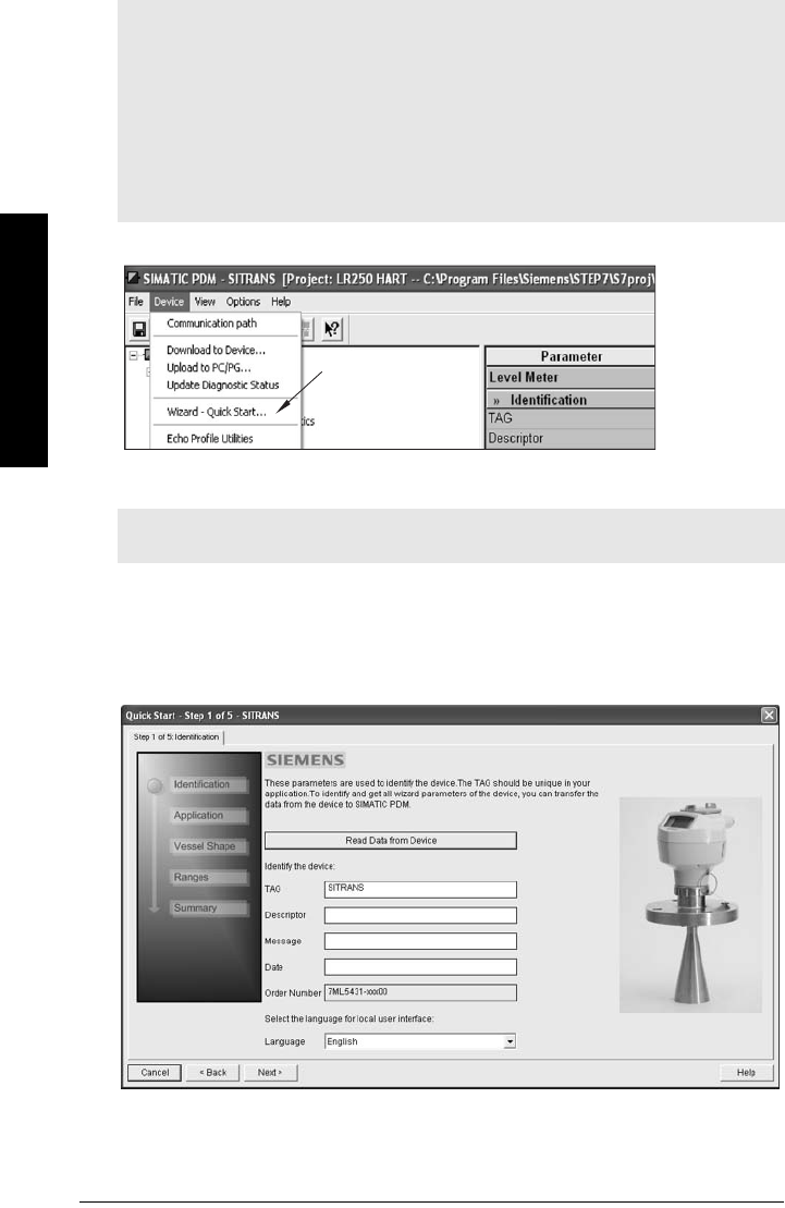
Page 42 SITRANS LR250 (HART) – INSTRUCTION MANUAL 7ML19985JE03
mmmmm
SIMATIC PDM
Quick Start
Launch SIMATIC PDM, open the menu Device – Wizard - Quick Start, and follow steps 1 to 5.
Step 1 – Identification
3) Click on Read Data from Device to upload Quick Start parameter settings from the
device to the PC/PG and ensure PDM is synchronized with the device.
4) If required, change the language for the local user interface.
5) Click on NEXT to accept the default values. (Description, Message, and Installation
Date fields can be left blank.)
Notes:
• The Quick Start wizard settings are inter-related and changes apply only after you
click on FINISH AND DOWNLOAD at the end of step 5 to save settings offline and
transfer them to the device.
• Do not use the Quick Start Wizard to modify individual parameters. For quick access
to echo profile parameters see
Echo Setup
on page 54, or see
Parameter Reference
on page 78 for a complete list.
•Click on BACK to return and revise settings or CANCEL to exit the Quick Start.
• For a vessel with obstructions see
Auto False Echo Suppression
on page 52.
Note: The layout of the dialog boxes shown may vary according to the resolution setting
for your computer monitor.
Quick
Start
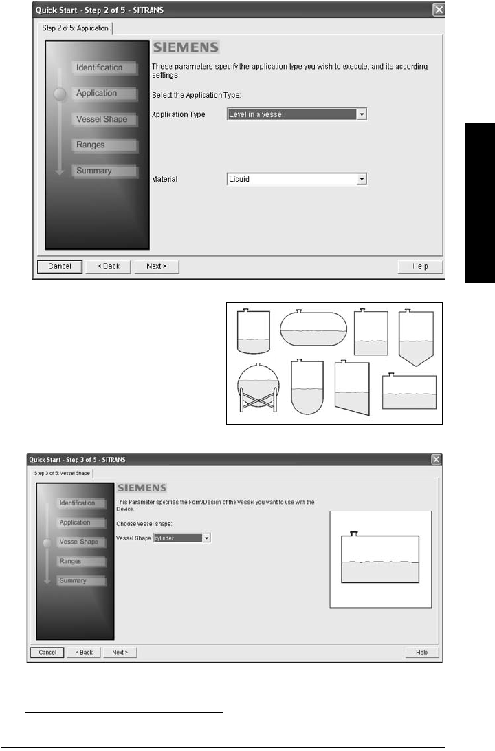
7ML19985JE03 SITRANS LR250 (HART) – INSTRUCTION MANUAL Page 43
mmmmm
SIMATIC PDM
Step 2 – Application
Select the application type (level or volume) and the material1), then click on NEXT.
Step 3 – Vessel Shape
The vessel shapes shown are
predefined. To describe a more complex
shape see
Using Linearization via the
Quick Start wizard
on page 45.
For a vessel with obstructions, see
Auto
False Echo Suppression
on page 52
Select the vessel shape, and click on NEXT.
1) See
Application with Stillpipe
on page 144 for a Low Dielectric Liquid application.
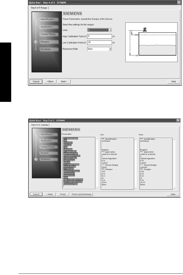
Page 44 SITRANS LR250 (HART) – INSTRUCTION MANUAL 7ML19985JE03
mmmmm
SIMATIC PDM
Step 4 – Range
Set the parameters, and click on NEXT.
Step 5 – Summary
Check parameter settings, and click on BACK to return and revise values, FINISH to save
settings offline, or FINISH AND DOWNLOAD to save settings offline and transfer them to
the device.
The message Quick Start was successful will appear. Click on OK.
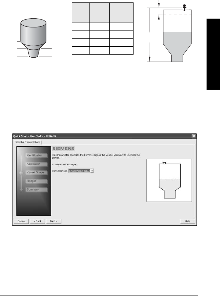
7ML19985JE03 SITRANS LR250 (HART) – INSTRUCTION MANUAL Page 45
mmmmm
SIMATIC PDM
Linearization
You can use the linearization feature to define a more complex vessel shape and enter up
to 32 level breakpoints where the corresponding volume is known. The values
corresponding to 100% and 0% levels must be entered. The breakpoints can be ordered
from top to bottom, or the reverse.
Example (values for example purposes only)
Using Linearization via the Quick Start wizard
Open the menu Device – Wizard - Quick Start:
1) In Step 1 – Identification, click on Read Data from Device, select language, and click
on Next.
2) In Step 2 – Application, select a volume application, for example Volume in a vessel,
and click on Next.
3) In Step 3 – Vessel Shape, choose the vessel shape option Linearization Table.
4
Breakpoint
number
3
2
1
Break-
point
no.
Level
value
(m)
Volume
value
(l)
10 0
25 500
3 9 3000
4 19.5 8000
Level
value
9
5
0
20 m
0.5 m
19.5
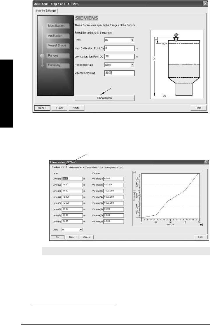
Page 46 SITRANS LR250 (HART) – INSTRUCTION MANUAL 7ML19985JE03
mmmmm
SIMATIC PDM
4) In Step 4 – Ranges
a) Enter parameter values.
b) Click on Linearization.
c) In the Linearization window click on the appropriate Breakpoint tab to open the
dialog window.
d) Enter the desired level and associated volume values1), and click on OK.
e) In the Step 4 window, click on NEXT.
Note: The Reset button resets values to the values in the offline table.
1) For display purposes we recommend entering values in ascending order (that is, the low-
est values in level 1 and volume 1).
Linearization
Breakpoints 1 - 8
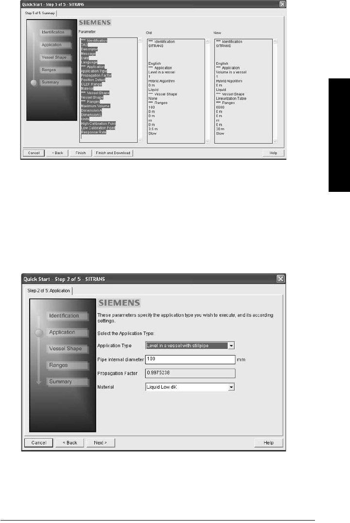
7ML19985JE03 SITRANS LR250 (HART) – INSTRUCTION MANUAL Page 47
mmmmm
SIMATIC PDM
5) In Step 5 – Summary, check parameter values. Click on BACK to return and revise
values, FINISH to save settings offline, or FINISH AND DOWNLOAD to save settings
offline and transfer them to the device.
The message Quick Start was successful will appear. Click on OK.
Configuring a stillpipe application
• Launch the Quick Start wizard and follow steps 1 to 2.
• In step 2, select Application Type – Level in a vessel with stillpipe, Material – Liquid
Low dK, and set the stillpipe diameter as desired.
• The wizard updates the propagation factor according to the pipe diameter, and
enables the CLEF algorithm for low dK liquids (see
Position Detect (2.8.4.2.)
on
page 127 for more detail).
• Continue through steps 3 to 5 then click on FINISH AND DOWNLOAD to save
settings offline and transfer them to the device.
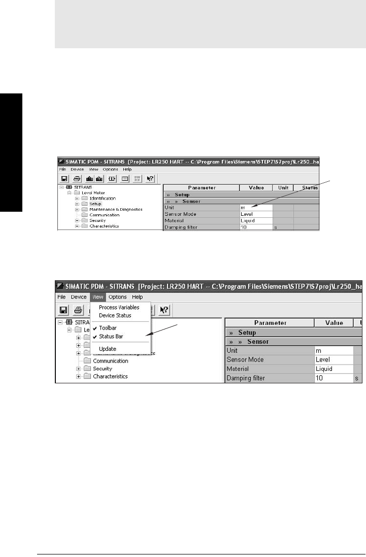
Page 48 SITRANS LR250 (HART) – INSTRUCTION MANUAL 7ML19985JE03
mmmmm
SIMATIC PDM
Changing parameter settings using SIMATIC PDM
Many parameters are accessed via the 4-level menu in PDM. See
Parameters accessed via
pull-down menus
below for the others.
1) Launch SIMATIC PDM, connect to SITRANS LR250, and upload data from the
device.
2) Adjust parameter values in the parameter value field then click on Enter. The status
fields read Changed.
3) Open the Device menu, click on Download to device, then use File – Save to save
settings offline. The status fields are cleared.
Parameters accessed via pull-down menus
Click on Device or View to open the associated pull-down menus.
See
Pull-down menus
on page 49 for a table.
Notes:
• For a complete list of parameters, see
Parameter Reference
on page 78.
• Clicking on Cancel during an upload from device to SIMATIC PDM will result in some
parameters being updated.
value
fields
pull-down
menus

7ML19985JE03 SITRANS LR250 (HART) – INSTRUCTION MANUAL Page 49
mmmmm
SIMATIC PDM
Pull-down menus
Echo Profile Utilities
Open the menu Device – Echo Profile Utilities and click on the appropriate tab for easy access
to:
•
Echo profile
on page 50
•
View Saved Echo Profiles
on page 50
•
TVT Shaper
on page 51
•
Auto False Echo Suppression
on page 52
•
Echo Setup
on page 54
Device menus page View menus page
Communication path Process Variables 57
Device Status 58
Download to device
Upload to PC/PG
Update Diagnostic Status
Toolb ar
Status bar
Wizard - Quick Start 42 Update
Echo Profile Utilities 49
Maintenance 54
Wear 56
Select Analog Output 55
Self Test 55
Loop Test 56
Configuration Flag Reset 56
Master Reset 56
HART Communication 56
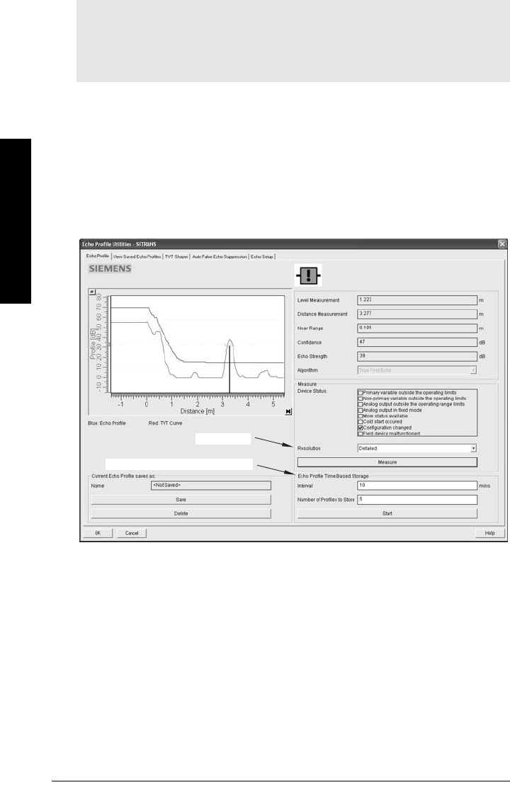
Page 50 SITRANS LR250 (HART) – INSTRUCTION MANUAL 7ML19985JE03
mmmmm
SIMATIC PDM
Echo profile
• In the Echo Profile Utilities window click on the tab Echo Profile.
• Click on the Measure button to update the profile. Select Standard resolution (loads
1 of every 8 points of the profile for a quick view) or Detailed resolution (loads all
data points).
• Click on the Save button and in the new window enter a name and click on OK.
•Click on OK to exit.
View Saved Echo Profiles
To view a saved profile, click on the tab View Saved Echo Profiles.
Echo profile data logging
You can store up to 50 profiles at a selected interval (maximum 60 minutes).
Inside Echo Profile Utilities, in the Echo Profile Time Based Storage window:
• Enter the desired interval between stored profiles.
• Enter the desired number of profiles to be stored (maximum 50).
•Click on Start. A message appears warning of the time delay and warning that all
previous saved profiles will be overwritten. Click on OK to proceed. The new profiles
will be saved with their date and time.
• Click on the tab View Saved Echo Profiles to view the stored profiles
Notes:
• Double click on each axis to see the Xscale and Data Scale values. Right-click or
Left-click on the axis and drag to reposition the scale.
• After saving a profile click on OK, not the x button, to close the Echo Profile Utilities
window, otherwise the profile will not be saved.
Echo Profile Time Based Storage
Resolution
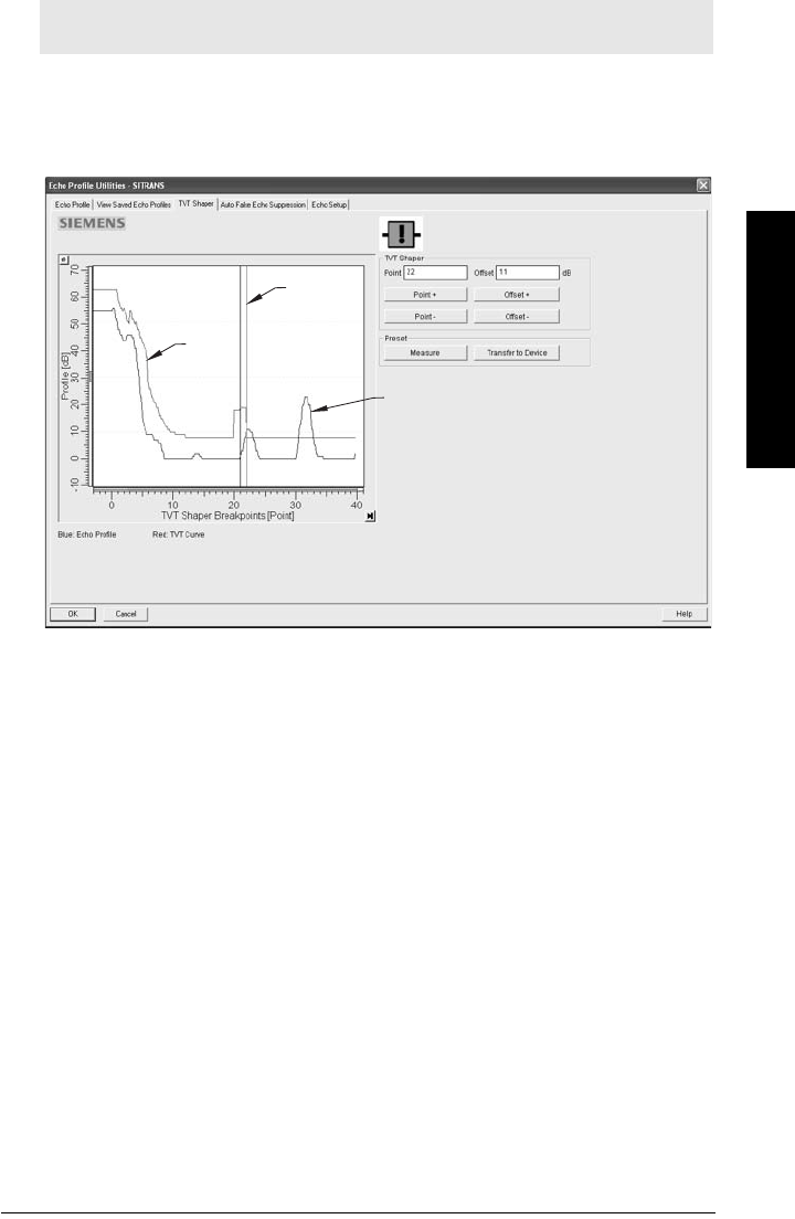
7ML19985JE03 SITRANS LR250 (HART) – INSTRUCTION MANUAL Page 51
mmmmm
SIMATIC PDM
TVT Shaper
This feature allows you to manually adjust the TVT to avoid false echoes caused by
obstructions. (For an explanation see
Auto False Echo Suppression (2.8.7.1.)
on page 130.)
Open the menu Device – Echo Profile Utilities and click on the tab TVT Shaper
•Click on Measure to refresh the echo profile and load the current TVT from the
device.
• Change the position of the cursor on the TVT using the Point+ and Point– buttons:
raise and lower the TVT using Offset+ and Offset–.
• Alternatively, enter values for Point and Offset directly into the dialog boxes.
•Click on Transfer to Device.
Note: Double click on each axis to see the Xscale and Data Scale values. Right-click or
Left-click on the axis and drag to reposition the scale.
TVT
cursor
echo
profile
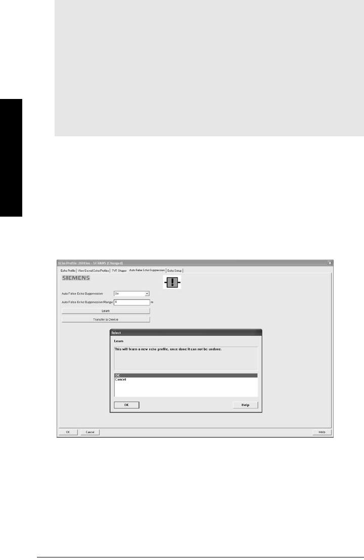
Page 52 SITRANS LR250 (HART) – INSTRUCTION MANUAL 7ML19985JE03
mmmmm
SIMATIC PDM
Auto False Echo Suppression
If you have a vessel with known obstructions, we recommend using Auto False Echo
Suppression to prevent false echo detection. This feature can also be used if the device
displays a false high level, or the reading is fluctuating between the correct level and a
false high level.
The device learns the echo profile over the whole measurement range and the TVT is shaped
around all echoes present at that moment. (See
Auto False Echo Suppression (2.8.7.1.)
on
page 130 for a more detailed explanation.)
The learned TVT will be applied over a specified range. The default TVT is applied over the
remainder of the measurement range.
1) Make sure the material level is below all known obstructions.
2) Determine Auto False Echo Suppression Range. Measure the actual distance from
the sensor reference point to the material surface using a rope or tape measure.
Subtract 0.5 m (20") from this distance, and use the resulting value.
Notes:
• Make sure material level is below all known obstructions at the moment Auto False
Echo Suppression is used to learn the echo profile. We recommend an empty or
almost empty vessel.
• Note the distance to material level when the environment is learned, and set Auto
False Echo Suppression Range to a shorter distance to avoid the material echo being
screened out.
• Set Auto False Echo Suppression and Auto False Echo Suppression Range during
startup, if possible.
• If the vessel contains an agitator it should be running.
• Before adjusting these parameters, rotate the instrument for best signal (lower
false-echo amplitude).
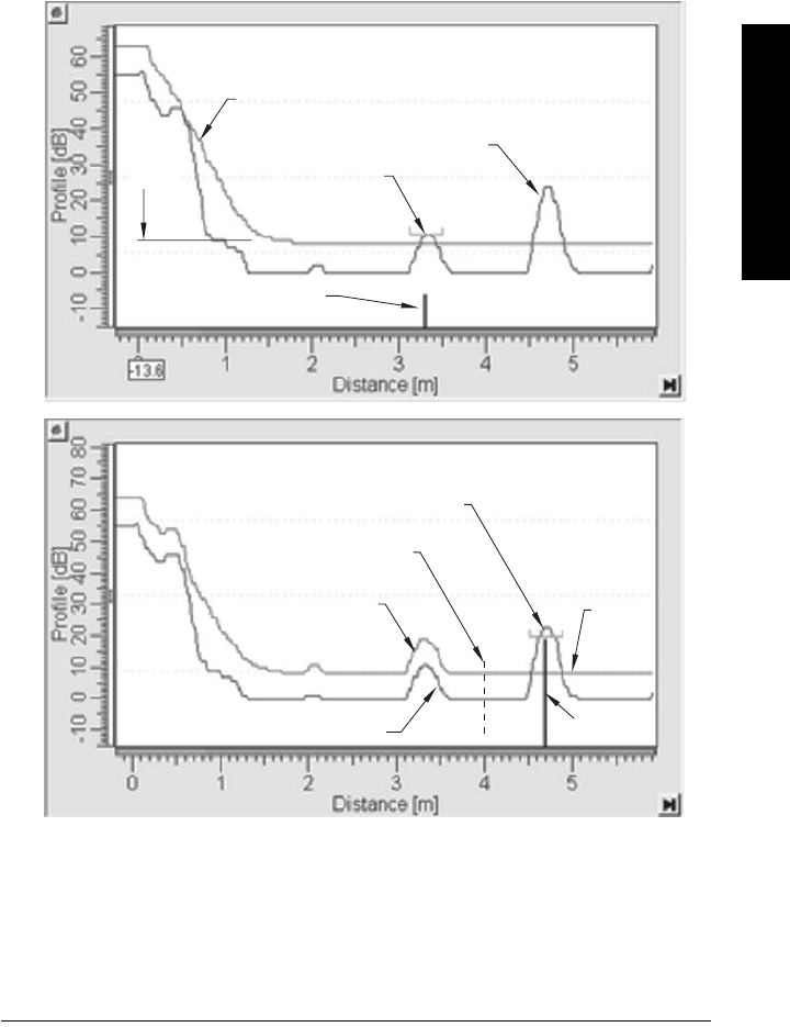
7ML19985JE03 SITRANS LR250 (HART) – INSTRUCTION MANUAL Page 53
mmmmm
SIMATIC PDM
3) Open the menu Device – Echo Profile Utilities and click on the tab Auto False Echo
Suppression.
4) Enter the value for Auto False Echo Suppression Range and select On.
5) Click on Learn. The message appears: ’This will learn a new echo profile. Once done
it cannot be undone’. Click on OK.
6) Once Auto TVT is complete click on Transfer to Device. To exit click on OK. Auto TVT
is enabled and the learned TVT will be used.
7) To turn Auto False Echo Suppression off or on, reopen the Auto False Echo
Suppression window and click on Off or On.
Before Auto False Echo Suppression
default TVT
TVT
Hover
Level
Level (db)
echo marker
After Auto False Echo Suppression
material level
false echo
Auto False Echo Suppression
Range
echo
marker
Level (db)
default
TVT
material level
false echo
learned TVT
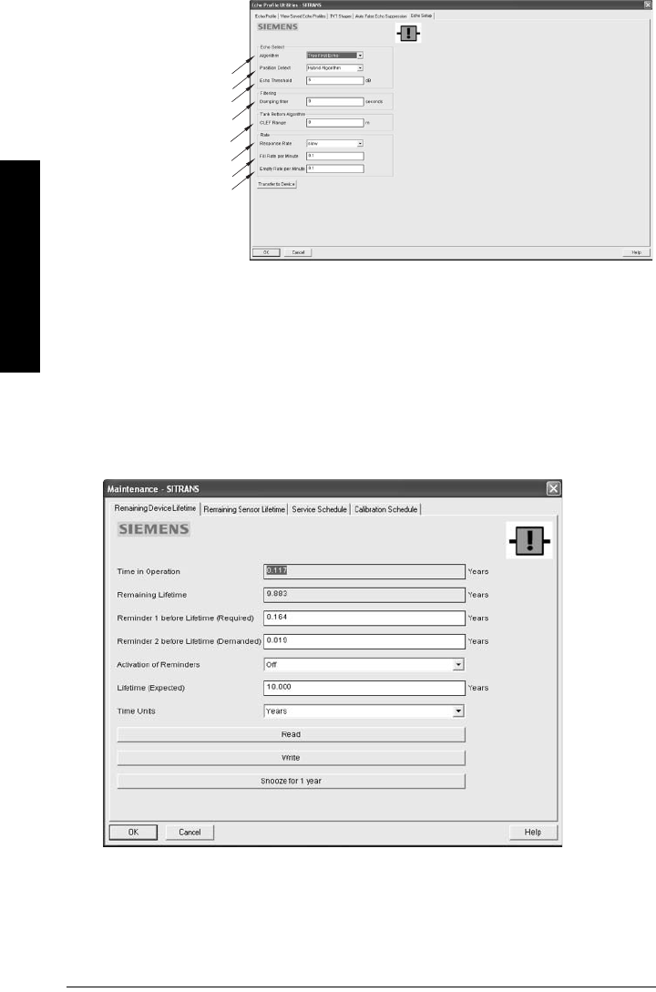
Page 54 SITRANS LR250 (HART) – INSTRUCTION MANUAL 7ML19985JE03
mmmmm
SIMATIC PDM
Echo Setup
Open the menu Device – Echo Profile Utilities and click on Echo Setup.
Maintenance
You can set schedules and reminders for:
• device maintenance based on its projected lifetime
• sensor maintenance based on its projected lifetime
•service
• calibration
To set Device/Sensor Maintenance schedules:
1) Open the menu Device – Maintenance, and click on the Remaining Device/Sensor
Lifetime tab.
Algorithm
Position Detect
Echo Threshold
Damping Filter
CLEF Range
Response Rate
Fill Rate/min.
Empty Rate/min.
Provides quick access
to echo profile
parameters:

7ML19985JE03 SITRANS LR250 (HART) – INSTRUCTION MANUAL Page 55
mmmmm
SIMATIC PDM
2) Modify desired values, and click on Write.
3) Click on Read, to see the effects of your modification.
4) If desired, set reminders for either or both of Reminder 1 (Required)/Reminder 2
(Demanded).
5) Click on Snooze to add a year to the Total Expected Device Life.
To set Service/Calibration schedules:
1) Open the menu Device – Maintenance, and click on the Service/Calibration
Schedule tab.
2) Modify desired values, and click on Write.
3) Click on Read, to see the effects of your modification.
4) If desired, set reminders for either or both of Reminder 1 (Required)/Reminder 2
(Demanded).
5) Click on Service/Calibration Performed to reset the schedule.
Select Analog Output
Allows you to set the mA Output to report Level, Distance. See Current Output Function
on page 84 for an illustration.
If a volume application is selected, mA Output is automatically set to Volume. (See Analog
Output on page 132 for more details.)
1) Open the menu Device – Select Analog Output.
2) The Select Analog Output window displays the current setting: click on OK.
3) Select a different setting and click on OK.
4) The Select Analog Output window displays the new setting: click on OK.
Self Test
Checks memory (RAM and Flash). If there are no errors, returns the message ’Self Test
OK.’ If errors are found, returns the message ’Self Test Fails’.
Open the menu Device – Self Test, select the option Yes and click on OK.

Page 56 SITRANS LR250 (HART) – INSTRUCTION MANUAL 7ML19985JE03
mmmmm
SIMATIC PDM
Loop Test
Allows you to input a simulated value (4 mA, 20 mA, or a user-defined value) in order to
test the functioning of the mA connections during commissioning or maintenance of the
device. (The range is 3.56 mA to 22.6 mA: see
mA Output Value (2.6.6.)
on page 86.)
To simulate a user-defined mA value:
1) Open the menu Device – Loop Test.
2) Select Other, enter the new value, and click on OK. The message ’Field Device fixed
at [new value]’ appears. Click on OK. The Loop Test window remains open.
3) When you are ready to end simulation, select End and click on OK to return the
device to the actual output value.
Configuration Flag Reset
To reset the configuration flag to zero, open the menu Device – Configuration Flag Reset and
perform a reset.
Master Reset
Factory Defaults
Factory Defaults resets all parameters to the default settings with the following
exceptions:
• Device Address
• Write Protect and PIN to unlock
• Learned TVT curve
1) Open the menu Device – Master Reset, select Yes, and click on OK to perform a
reset to Factory Defaults.
2) After the reset is complete upload parameters to the PC/PG. (If you are performing a
reset after replacing the device with a different instrument, do not upload
parameters to the PC/PG).
Wear
Reports the number of hours the device has been operating, and the number of times it
has been powered up.
Open the menu Device – Wear to view:
• Powered Days
• Power-on Resets
HART Communication
Sets the number of request/response preambles (default 5).
We recommend you do not change this value.
Diagnostics
You can monitor level/volume trends, electronics temperature, and device status.
Note: The simulated AO (Analog Output) value influences output to the control system.
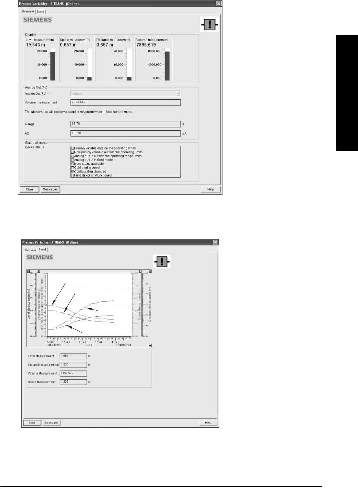
7ML19985JE03 SITRANS LR250 (HART) – INSTRUCTION MANUAL Page 57
mmmmm
SIMATIC PDM
Process Variables
To compare outputs in real time open the menu View – Process Variables and click on
Overview to see reading (level, space, distance, volume); analog output; device status; and
current electronics temperature.
To see highest and lowest electronics temperatures, navigate to Level Meter > Maintenance
and Diagnostics > Electronics Temperature.
Trend
Open the menu View – Process Variables and click on Trend.
space
4 trend lines can be
monitored:
(distinguished by color in
SIMATIC PDM).
distance
level
volume
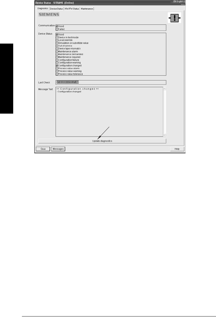
Page 58 SITRANS LR250 (HART) – INSTRUCTION MANUAL 7ML19985JE03
mmmmm
SIMATIC PDM
Device Status
Open the menu View – Device Status to view Diagnostics, Device Status, Hardware/
Firmware (HW/FW) Status, and Maintenance status.
In the Diagnostics window, click on Update diagnostics to update diagnostic information
and refresh linked icons.
Update
Open the menu View – Update to refresh the screen.
Security
A password option protects security and communication control parameters from
modification by a maintenance user.
When you open a project the User dialog window provides two options: maintenance or
specialist. If a password has been set it will not be possible to open the project as a specialist
without it. A maintenance user will be able to open the project without a password but will not
have access to security and communication control parameters.
1) Open a project, double-click on the device icon, and in the User window select
Specialist.
2) Open the menu Options – Settings and click on the Password tab.
3) Enter a new password and re-enter it in the Confirmation window. Click on OK.
update diagnostics
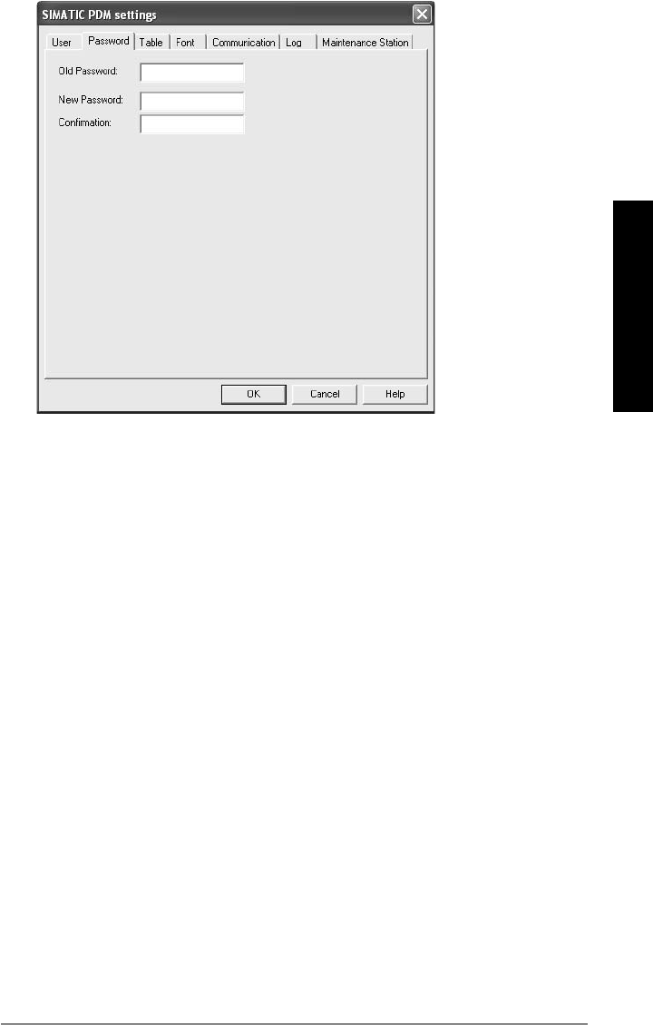
7ML19985JE03 SITRANS LR250 (HART) – INSTRUCTION MANUAL Page 59
mmmmm
SIMATIC PDM

Page 60 SITRANS LR250 (HART) – INSTRUCTION MANUAL 7ML19985JE03
mmmmm
AMS Device Manger
Operating via AMS Device Manager
AMS Device Manager is a software package used to commission and maintain SITRANS
LR250 and other process devices. Please consult the operating instructions or online help for
details on using AMS Device Manager. (You can find more information at
http://www.emersonprocess.com/AMS/.) Application Guides for setting up Siemens HART
devices with AMS Device Manager are available on our website at:
www.siemens.com/processautomation.
Functions in AMS Device Manager
AMS Device Manager monitors the process values, alarms and status signals of the device. It
allows you to display, compare, adjust, verify, and simulate process device data
Parameters organized into three main function groups allow you to configure and monitor
the device:
• Configure/Setup
• Device Diagnostics (read only)
• Process Variables (read only)
See
AMS Menu Structure
on page 73 for a chart1) and
Changing parameter settings
using AMS Device Manager
on page 65 for more details.
Features of AMS Device Manager
The graphic interface in SITRANS LR250 makes monitoring and adjustments easy.
Note: While the device is in PROGRAM mode the output remains fixed and does not
respond to changes in the device.
1) The menu structure for AMS Device Manager is almost identical to that for the LCD.
Feature page Function
Quick Start 63 Device configuration for simple applications
Echo Profile 69 Echo profile viewing
TVT 68 Screen out false echoes
Linearization 64 Volume measurement in an irregular vessel
Process Variables 71 Monitor process variables and level trend
Security 70 Protect security and communication parameters
from modification by the maintenance user
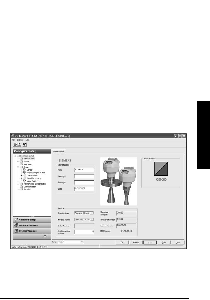
7ML19985JE03 SITRANS LR250 (HART) – INSTRUCTION MANUAL Page 61
mmmmm
AMS Device Manger
Device Description (DD)
SITRANS LR250 requires the DD for AMS Device Manager version 9.0.
You can locate the DD in Device Catalog, under Sensors/Level/Echo/Siemens Milltronics/
SITRANS LR250. Check the product page of our website at: www.siemens.com/LR250, under
Downloads, to make sure you have the latest version of AMS Device Manager. If you need
to install a new DD see
Configuring a new device
below.
Configuring a new device
1) Check that you have the most recent DD, and if necessary download it from the
product page listed above. Save the files to your computer, and extract the zipped
file to an easily accessed location.
2) Launch AMS Device Manager– Add Device Type, browse to the unzipped DD file
and select it.
Startup
1) Launch AMS Device Manager. (Application Guides for setting up HART devices with
AMS Device Manager can be downloaded from the product page of our website at:
www.siemens.com/LR250.)
2) In Device Connection View right-click on the device icon and select Scan Device to
upload parameters from the device.
3) Double click the device icon to open the startup screen. The startup screen shows
device identification details, and a navigation window on the left-hand side of the
screen.
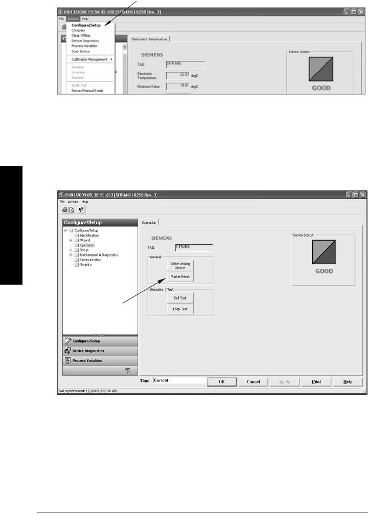
Page 62 SITRANS LR250 (HART) – INSTRUCTION MANUAL 7ML19985JE03
mmmmm
AMS Device Manger
Master Reset
• Navigate to Configure/Setup > Operation
• In the General field click on Master Reset and accept the option Factory Defaults.
Pull-down menu access
A pull-down menu under Actions gives alternative access to several features.
Scan Device
• Open the menu Actions – Scan Device.
•Scan Device uploads parameters from the device (synchronizes parameters).
Device configuration
1) Navigate to Configure/Setup > Operation and click to open the dialog window.
2) In the General field, click on Master Reset and perform a reset to Factory Defaults.
3) Open the pull-down menu Actions – Scan Device to synchronize parameters (upload
parameters from the device to AMS).
4) Configure the device via the Quick Start wizard.
Action menu items
Master
Reset
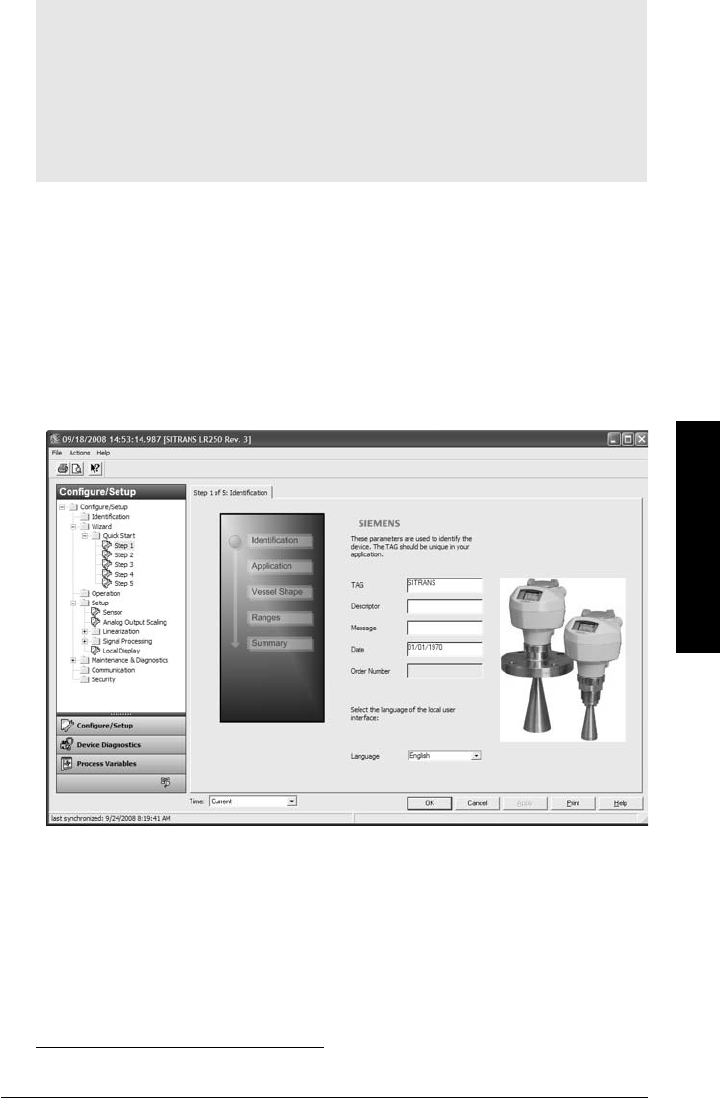
7ML19985JE03 SITRANS LR250 (HART) – INSTRUCTION MANUAL Page 63
mmmmm
AMS Device Manger
Quick Start Wizard via AMS Device Manager
A Wizard provides an easy 5-step Quick Start procedure that configures the device for a
simple application.
Quick Start
Step 1 – Identification
1) Navigate to Configure/Setup > Wizard > Quick Start.
2) Click on Step 1.
3) You can accept the default values without modification. (Description, Message, and
Installation Date fields can be left blank.) If desired, make changes then click on
Apply.
Step 2 – Application Type
1) Click on Step 2.
2) Select the application type (Level, Space, Distance, or No Service1)) and the material
(Liquid or Low dielectric liquid).
3) Click on Apply.
Notes:
• The layout of the dialog boxes shown may vary according to the resolution setting
for your computer monitor
• At each step, you can accept the default values without modification and click on the
next step to proceed.
• After modifying parameters click on Apply inside the Quick Start window to write the
new values to the device.
•Click on OK only if you wish to update all parameters to the device and close AMS.
1) For details see
Sensor Mode
on page 133.
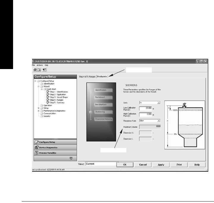
Page 64 SITRANS LR250 (HART) – INSTRUCTION MANUAL 7ML19985JE03
mmmmm
AMS Device Manger
Step 3 – Vessel Shape
1) Click on Step 3.
2) Select a predefined vessel shape. (To describe a more complex shape see
Linearization
below.)
3) Click on Apply.
Step 4 – Range
1) Click on Step 4.
2) Change units if desired (in meters by default).
3) Set High and Low Calibration points.
4) To convert the reading from level to volume enter a value for Maximum Volume.
5) If a vessel shape with parabolic ends has been selected, set dimensions A and L.
6) Click on Apply.
Step 5 – Summary
Check parameter settings, and click on Cancel to abort, or Apply to transfer values to the
device.
Linearization
You can use the linearization feature to define a more complex vessel shape and enter up to
32 level breakpoints where the corresponding volume is known. The values corresponding to
100% and 0% levels must be entered. The breakpoints can be ordered from top to bottom, or
the reverse. (See
Linearization
on page 45 for an example.)
Using Linearization via the Quick Start wizard
1) Navigate to Configure/Setup > Wizard > Quick Start.
2) In Step 1 – Identification make any desired modifications and click on Apply.
3) In Step 2 – Application Type select a level application and liquid as a material.
4) In Step 3 – Vessel Shape, choose the vessel shape option Linearization Table.
5) In Step 4 – Range Setup enter a value for maximum volume.
Breakpoints
max. volume
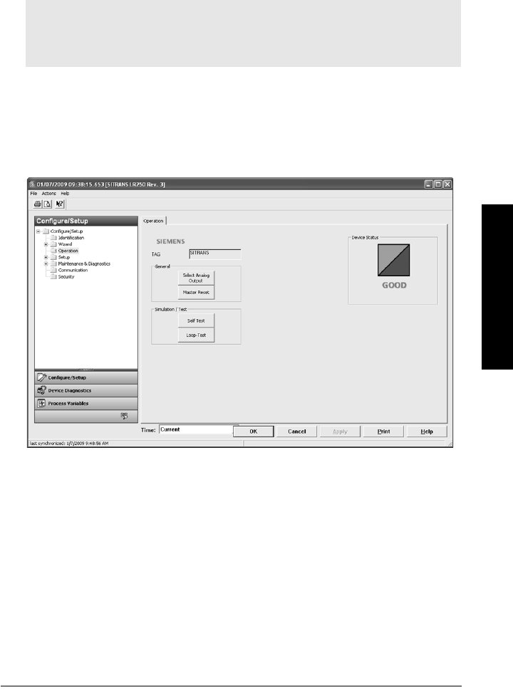
7ML19985JE03 SITRANS LR250 (HART) – INSTRUCTION MANUAL Page 65
mmmmm
AMS Device Manger
6) Click on the Breakpoints tab and enter values for level and volume for up to 32
breakpoints.
7) Navigate to Configure/Setup > Setup > Linearization and click on Characteristic to
preview the characteristic curve of the vessel breakpoints.
8) In Step 5 – Summary check parameter values. Click on the appropriate step menu to
return and revise values, or click on a different menu to exit Quick Start.
Changing parameter settings using AMS Device Manager
1) Adjust parameter values in the parameter value field in Configure/Setup view, then
click on Apply to write the new values to the device. The parameter field will display
in yellow until the value has been written to the device.
2) Click on OK only if you wish to update all parameters and exit AMS.
Operation
Navigate to Configure/Setup > Operation and click on Operation to open the dialog window for
access to:
General:
• Select Analog Output (see
Select Analog Output
on page 55)
•D/A Trim
•Master Reset (see
Master Reset
on page 56)
Simulation/Test
• Self Test (see
Self Test
on page 55)
• Loop Test (see
Loop Test
on page 56)
Notes:
• For a complete list of parameters, see
Parameter Reference
on page 78.
• For more detailed explanations of the parameters listed below see the pages
referenced.
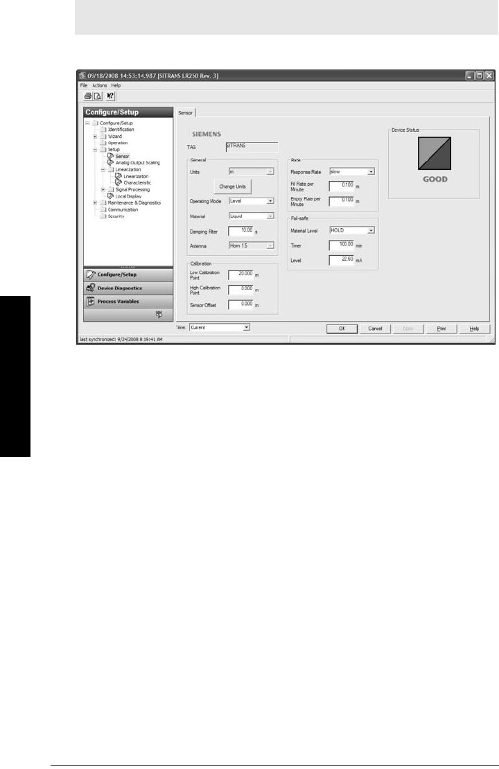
Page 66 SITRANS LR250 (HART) – INSTRUCTION MANUAL 7ML19985JE03
mmmmm
AMS Device Manger
Setup
Sensor
Navigate to Configure/Setup > Setup and click on Sensor for access to:
General [see Sensor (2.2.) on page 79]
•Units
• Operating Mode
•Material
• Damping Filter
• Antenna (read only)
Calibration [see Calibration (2.3.) on page 80]
• Low Calibration Point
• High Calibration Point
• Sensor Offset
Rate [see Rate (2.4.) on page 81]
• Response Rate
• Fill rate/minute
• Empty rate/minute
Fail-safe [see Fail-safe (2.5.) on page 83]
• Material level
•Timer
•Level
Note: For more detailed explanations of the parameters listed below see the pages
referenced.
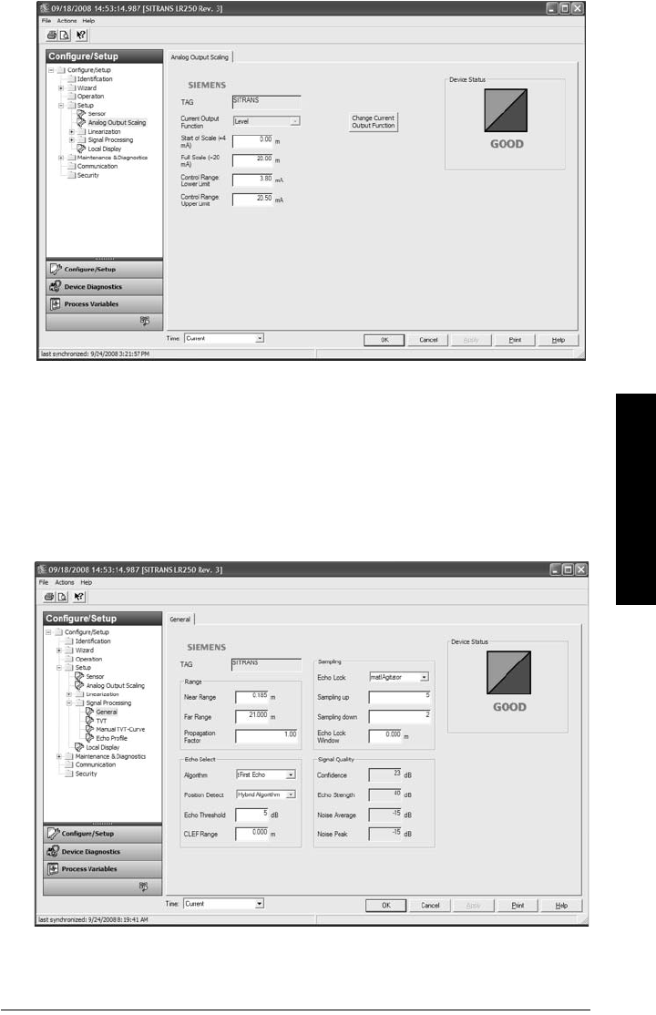
7ML19985JE03 SITRANS LR250 (HART) – INSTRUCTION MANUAL Page 67
mmmmm
AMS Device Manger
Analog Output Scaling
Navigate to Configure/Setup > Setup and click on Analog Output Scaling for access to:
Analog Output Scaling [see Analog Output Scaling (2.6.) on page 84]
• mA Output Function
• Start of scale
• Full Scale
• Control Range (lower limit)
• Control Range (upper limit)
Signal Processing
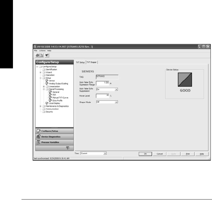
Page 68 SITRANS LR250 (HART) – INSTRUCTION MANUAL 7ML19985JE03
mmmmm
AMS Device Manger
Signal Processing (continued)
General
Navigate to Configure/Setup > Setup > Signal Processing and click on General for access to:
Range [see Signal Processing (2.8.) on page 90]
•Near Range
• Far Range
• Propagation Factor
Echo Select [see Echo select (2.8.4.) on page 91]
• Algorithm
• Position Detect
• Echo Threshold
• CLEF Range
Sampling [see Sampling (2.8.5.) on page 92]
• Echo Lock
• Sampling Up
• Sampling Down
• Echo Lock Window
Signal Quality
• Confidence
• Echo Strength
•Noise Average
•Noise Peak
TVT
Modify the TVT to screen out false echoes [see
Auto False Echo Suppression (2.8.7.1.)
on
page 130].

7ML19985JE03 SITRANS LR250 (HART) – INSTRUCTION MANUAL Page 69
mmmmm
AMS Device Manger
Navigate to Configure/Setup > Setup > Signal Processing and click on TVT. Click on one of the
two tabs to access the parameters listed:
TVT Setup [see TVT setup (2.8.7.) on page 94]
• Auto False Echo Suppression Range
• Auto False Echo Suppression
•Hover Level
• Shaper Mode
TVT Shaper
• Shaper breakpoints 1 to 40. (Turn TVT Setup/Shaper Mode on to activate.)
Manual TVT Curve
Displays the effects of the TVT shaper modifications. Navigate to Configure/Setup > Setup >
Signal Processing and click on Manual TVT Curve.
Echo Profile
• Navigate to Configure/Setup > Setup > Signal Processing and click on Echo
Profile.
• Select Standard operation for faster display.
Local Display
Navigate to Configure/Setup > Setup > Local Display for access to:
• Language
• LCD Fast Mode [see LCD Fast Mode (4.9.) on page 112]
• LCD Contrast [see LCD Contrast (4.10.) on page 112]
Maintenance and Diagnostics
Navigate to Maintenance and Diagnostics for access to:
Remaining Device Lifetime [see Remaining Device Lifetime (4.2.) on page 99]
• Lifetime expected
• Remaining Lifetime
• Time in Operation
• Activation of Reminders
• Reminder 1 before Lifetime (Required)
• Reminder 2 before Lifetime (Demanded)
Remaining Sensor Lifetime [see Remaining Sensor Lifetime (4.3.) on page 102]
• Lifetime expected
• Remaining Lifetime
• Time in Operation
• Activation of Reminders
• Reminder 1 before Lifetime (Required)
• Reminder 2 before Lifetime (Demanded)
Service Schedule [see Service Schedule (4.4.) on page 105]
•Service Interval
• Time since last Service
• Time until next Service
• Activation of Reminders
• Reminder 1 before Service (Required)
• Reminder 2 before Service (Demanded)

Page 70 SITRANS LR250 (HART) – INSTRUCTION MANUAL 7ML19985JE03
mmmmm
AMS Device Manger
Calibration Schedule [see Calibration Schedule (4.5.) on page 108]
• Calibration Interval
• Time since last Calibration
• Time Until Next Calibration
• Activation of Reminders
• Reminder 1 before Calibration (Required)
• Reminder 2 before Calibration (Demanded)
Electronic Temperature
• Electronic Temperature
•Lowest Value
• Highest Value
Wear (see
Wear
on page 56)
• Powered days
•Poweron Resets
Communication
Navigate to Communication to read the following:
Tag; Manufacturer’s ID; Device ID; Product ID; Device Revision; EDD Revision; Universal
Command
Security
Navigate to Configure/Setup > Security to access:
Remote Access [see Remote Access (6.1.) on page 113]
• Write Protect (read only)
• Access Control
Local Access [see Local Access (6.2.) on page 114]
• Local Write Protected
• PIN to Unlock
See also
Password Protection
on page 72
Note: If access control is changed to limit remote access, it can only be reset via
the handheld programmer. See Ac cess C ontrol ( 6.1.1.) on page 113.
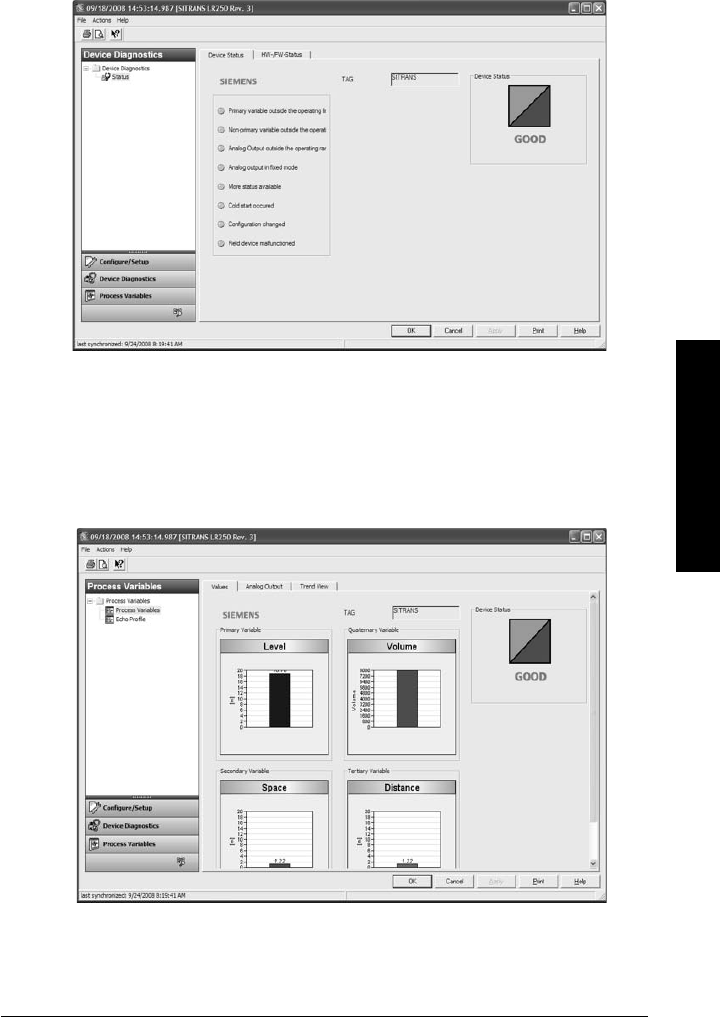
7ML19985JE03 SITRANS LR250 (HART) – INSTRUCTION MANUAL Page 71
mmmmm
AMS Device Manger
Device Diagnostics
Click on the Device Diagnostics bar at the bottom of the navigation window, for access to:
Device Status
Hardware/Firmware Status
Process Variables
To compare outputs in real time click on Process Variables at the bottom of the navigation
window. for access to:
Process Variables
• Values (level, volume, space, distance)
• Analog Output
•Trend View
Echo Profile
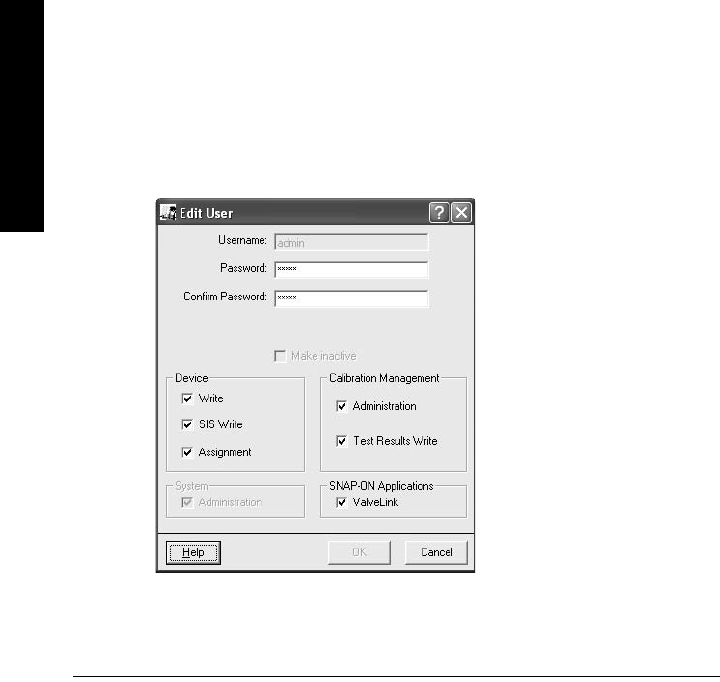
Page 72 SITRANS LR250 (HART) – INSTRUCTION MANUAL 7ML19985JE03
mmmmm
AMS Device Manger
Password Protection
An AMS Device Manager administrator can configure the user to require a password. The use
of passwords is recommended. A password should be assigned to the ’admin’ username
immediately after installing AMS Device Manager.
Each user is given an AMS Device Manager username and password and required to enter
them when they start AMS Device Manager. Access to functions depends on the level of
permissions granted.
Login types
• standard, local, or domain
A standard user can change their password in AMS Device Manager. A Local or Domain
Windows user cannot change their password using AMS Device Manager and must request
their network administrator to do so.
User Manager utility
Usernames, passwords, and permissions, are assigned to users by an AMS Device Manager
administrator, using the User Manager utility on the Server Plus Station. Only a user with AMS
Device Manager System Administration rights can log in to User Manager.
To configure a new user/edit existing user:
1) From the Windows taskbar select: Start > AMS Device Manager > User Manager.
2) In the User Manager window click on Add User.
The Add User Wizard dialog allows you to:
• select a user type, standard (AMS Device Manager) or Window user.
• enter the username and password, and set permissions
• edit existing users

7ML19985JE03 SITRANS LR250 (HART) – INSTRUCTION MANUAL Page 73
mmmmm
AMS Device Manger
AMS Menu Structure
Configure/Setup
Identification
Identification
Tag
Description
Message
Date
Device
Manufacturer
Product Name
Order Number
Final Assembly Number
Hardware Revision
Firmware Revision
Loader Revision
EDD number
Wizard
Quick Start
Step 1 (Identification)
Step 2 (Application Type)
STep 3 (Vessel Shape)
Step 4 (Range)
Step 5 (Summary)
Operation
General
Select Analog Output
D/A Trim
Master Reset
Simulation/Test
Self Test
Loop-Test
Setup
Sensor
General
Units
Operating Mode
Material
Damping Filter
Antenna

Page 74 SITRANS LR250 (HART) – INSTRUCTION MANUAL 7ML19985JE03
mmmmm
AMS Device Manger
Configure/Setup (continued)
Setup/Sensor (continued)
Calibration
Low Calibration Point
High Calibration Point’
Sensor Offset
Rate
Response Rate
Fill rate/minute
Empty rate/minute
Fail-safe
Timer
Material Level
Level
Analog Output Scaling
Analog Output Scaling
mA Output Function
Start of Scale
Full Scale
Control Range lower limit
Control Range upper limit
Linearization
Linearization
Vessel Shape
Vessel dimensions
Max. volume
Dimension A
Dimension L
Characteristic
Signal Processing
General
Range
Near Range
Far Range
Propagation Factor
Echo Select
Algorithm
Position Detect
Echo Threshold
CLEF Range
Sampling
Echo Lock
Sampling Up
Sampling Down
Echo Lock Window.

7ML19985JE03 SITRANS LR250 (HART) – INSTRUCTION MANUAL Page 75
mmmmm
AMS Device Manger
Configure/Setup (continued)
Setup/Signal Processing (continued)
Signal Quality
Confidence
Echo Strength
Noise average
Noise Peak
TVT
TVT Setup
Auto False Echo Suppression Range
Auto False Echo Suppression
Hover Level
Shaper Mode
TVT Shaper
Manual TVT Curve
Echo Profile
Local Display
Maintenance and Diagnostics
Remaining Device Lifetime
Lifetime expected
Remaining Lifetime
Time in Operation
Activation of Reminders
Reminder 1 before Lifetime (Required)
Reminder 2 before Lifetime (Demanded)
Remaining Sensor Lifetime
Lifetime expected
Remaining Lifetime
Time in Operation
Activation of Reminders
Reminder 1 before Lifetime (Required)
Reminder 2 before Lifetime (Demanded)

Page 76 SITRANS LR250 (HART) – INSTRUCTION MANUAL 7ML19985JE03
mmmmm
AMS Device Manger
Maintenance and Diagnostics (continued)
Service Schedule
Service Interval
Time since last Service
Total Service Interval minus Time Since Last Service
Activation of Reminders
Reminder 1 before Service (Required)
Reminder 2 before Service (Demanded)
Calibration Schedule
Calibration Interval
Time since last Calibration
Total Until Next Calibration
Activation of Reminders
Reminder 1 before Calibration (Required)
Reminder 2 before Calibration (Demanded)
Electronic Temperature
Electronic Temperature
Lowest Value
Highest Value
Wear
Powered days
Poweron Resets
Communication
Security
Remote Access
Write Protect
Access Control
Local Access
Local Write Protected
PIN to Unlock

7ML19985JE03 SITRANS LR250 (HART) – INSTRUCTION MANUAL Page 77
mmmmm
AMS Device Manger
Notes

Page 78 SITRANS LR250 (HART) – INSTRUCTION MANUAL 7ML19985JE03
mmmmm
Parameters
Parameter Reference
Parameters are identified by name and organized into function groups. See
LCD menu
structure
on page 165 for a chart1).
Parameters accessible via the handheld programmer are preceded by a number.
Parameters not preceded by a number are accessible only via remote operation.
For more details see:
•
Operating via SIMATIC PDM
on page 40
•
Operating via AMS Device Manager
on page 60
Quick Start Wizard
The Quick Start wizard provides an easy step-by-step procedure to configure the device
for a simple application.
1. Quick Start
1.1. Language
1.2. Material
1.3. Response Rate
1.4. Units
Notes:
• Parameter names and menu structure are almost identical for SIMATIC PDM and the
local user interface (LUI)1).
• Default settings in the parameter tables are indicated with an asterisk (*) unless
explicitly stated.
•Mode toggles between PROGRAM and Measurement Modes.
• For Quick Access to parameters via the handheld programmer, press Home , then
enter the menu number, for example: 2.2.1.
1) For AMS Device Manager the structure varies slightly.
Notes:
• Do not use the Quick Start wizard to modify individual parameters. (Perform
customization only after the Quick Start has been completed.)
• For access via remote operation see
Quick Start Wizard via SIMATIC PDM
on page
41 or
Quick Start Wizard via AMS Device Manager
on page 63.
• For detailed instructions see
Quick Start Wizard via the handheld programmer
on
page 36.
• In Navigation mode, ARROW keys navigate the menu in the direction of
the arrow.
•Press RIGHT arrow to open Edit Mode, or to save a modification.
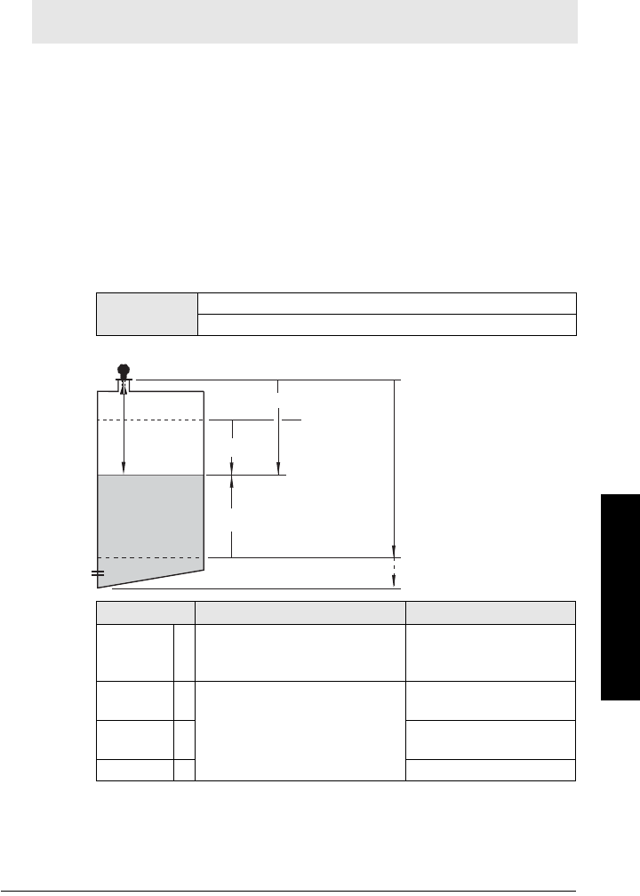
7ML19985JE03 SITRANS LR250 (HART) – INSTRUCTION MANUAL Page 79
mmmmm
Parameters
1.5. Operation Mode
1.6. Low Calibration Point
1.7. High Calibration Point
1.8. Apply? (Apply changes)
2. Setup
2.1. Device
2.1.1. Hardware Revision
Corresponds to the electronics hardware of the SITRANS LR250.
2.1.2. Firmware Revision
Corresponds to the firmware that is embedded in the SITRANS LR250.
2.1.3. Loader Revision
Corresponds to the software used to update the SITRANS LR250.
2.1.4. Order Option
Read only. Displays the device type: standard or NAMUR NE 43-compliant.
2.2. Sensor
2.2.1. Units
Sensor measurement units.
2.2.2. Sensor Mode
Note: Default settings in the parameter tables are indicated with an asterisk (*) unless
explicitly stated.
Values m, cm, mm, ft, in
Default: m
Mode Description Reference point
NO
SERVICE
Measurement and associated loop
current are not updated, and the
device defaults to Fail-safe modea).
a) See Material Level (2.5.1.) for more detail.
n/a
LEVEL *
Distance to material surface
Low Calibration Point
(process empty level)
SPACE High Calibration Point
(process full level)
DISTANCE Sensor Reference Point
sensor reference point
(see
Dimensions
on page
12 and
Flanged Horn with
extension
on page 14)
Level
Low
Calibration
Point
High
Calibration
Point
Far Range
sensor
value
Distance
Space

Page 80 SITRANS LR250 (HART) – INSTRUCTION MANUAL 7ML19985JE03
mmmmm
Parameters
2.2.3. Material
Automatically configures the device to operate in the chosen application type,
by changing one or more of the following parameters: Propagation Factor
(2.8.3.), Position Detect (2.8.4.2.), and/or CLEF Range (2.8.4.4.).
You can configure each of the related parameters, to suit your particular
application.
2.2.4. Damping Filter
The time constant for the damping filter. The damping filter smooths out the re-
sponse to a sudden change in level. This is an exponential filter and the engi-
neering unit is always in seconds (see Damping on page 132 for more detail).
Antenna
Read only. Identifies horn configuration (Near Range (blanking) distance is au-
tomatically adjusted to suit).
2.3. Calibration
2.3.1. Low Calibration Pt.
Distance from sensor reference point
1)
to Low Calibration Point.
Units are
defined in Units (2.2.1.)
Options
*LIQUID
LIQUID LOW DKa) (low dielectric liquid – CLEF algorithm
enabled)
a) dK < 3.0
Related
parameters
Propagation Factor (2.8.3.)
Position Detect (2.8.4.2.)
CLEF Range (2.8.4.4.)
Values Range: 0 to 100.000 s
Default: 10.000 s
Note: We recommend using the Quick Start wizard to configure the device.
1) The point from which level measurement is referenced (see Sensor Mode (2.2.2.) for
an illustration).
Values Range: 0 to 20 m. Default 20.00 m
Related
parameters
Units (2.2.1.)
Far Range (2.8.2.)

7ML19985JE03 SITRANS LR250 (HART) – INSTRUCTION MANUAL Page 81
mmmmm
Parameters
2.3.2. High Calibration Pt.
Distance from sensor reference point
1)
to High Calibration Point. Units are
defined in Units (2.2.1.).
When setting the High Calibration Point value, note that echoes are ignored
within Near Range (2.2.1.11).
2.3.3. Sensor Offset
A constant offset that can be added to or subtracted from sensor value
1)
to
compensate if the sensor reference point has shifted. (For example, this could
result from adding a thicker gasket or reducing the standoff/nozzle height.)
2.4. Rate
2.4.1. Response Rate
Sets the reaction speed of the device to measurement changes.
Use a setting just faster than the maximum filling or emptying rate (whichever
is faster).
Values Range: 0 to 20 m. Default 0.00 m
Related parameters Units (2.2.1.)
Near Range (2.8.1.)
1) The value produced by the echo processing which represents the distance from sen-
sor reference point to the target. (see Sensor Mode (2.2.2.) on page 79 for an illustra-
tion).
Values Range: -99.999 to 99.999. Default: 0.00 m
Related
parameters Units (2.2.1.)
Note: Default settings in the parameter tables are indicated with an asterisk (*)
unless explicitly stated.
Note: Changing Response Rate resets Fill Rate (2.4.2.), Empty rate (2.4.3.), and
Damping Filter (2.2.4.).
Response Rate
(2.4.1.)
Fill Rate
(2.4.2.)
Empty rate
(2.4.3.)
Damping Filter
(2.2.4.)
*Slow 0.1 m/min (0.32 ft/min) 10 s
Medium 1.0 m/min (3.28 ft/min) 10 s
Fast 10.0 m/min (32.8 ft/min) 0 s

Page 82 SITRANS LR250 (HART) – INSTRUCTION MANUAL 7ML19985JE03
mmmmm
Parameters
2.4.2. Fill Rate
Defines the maximum rate at which the reported sensor value
1)
is allowed to
increase. Allows you to adjust the SITRANS LR250 response to increases in the
actual material level. Fill Rate is automatically updated whenever Response
Rate is altered.
Enter a value slightly greater than the maximum vessel-filling rate, in units per
minute.
2.4.3. Empty rate
Defines the maximum rate at which the reported sensor value
2)
is allowed to
decrease. Adjusts the SITRANS LR250 response to decreases in the actual
material level. Empty Rate is automatically updated whenever Response Rate
is altered.
Enter a value slightly greater than the vessel’s maximum emptying rate, in units
per minute.
1) The value produced by the echo processing which represents the distance from sen-
sor reference point to the target (see Sensor Mode (2.2.2.) on page 79 for an illustra-
tion).
Options
Range: 0 to 99999 m / min.
Response Rate (2.4.1.) Fill Rate
* Slow 0.1 m/min (0.32 ft/min)
Medium 1.0 m/min (3.28 ft/min)
Fast 10.0 m/min (32.8 ft/min)
Altered by: Response Rate (2.4.1.)
Related
parameters Units (2.2.1.)
2) The value produced by the echo processing which represents the distance from sen-
sor reference point to the target (see Sensor Mode (2.2.2.) on page 79 for an illustra-
tion).
Options
Range: 0 to 99999 m / min.
Response Rate (2.4.1.) Empty Rate
* Slow 0.1 m/min (0.32 ft/min)
Medium 1.0 m/min (3.28 ft/min)
Fast 10.0 m/min (32.8 ft/min)
Altered by: Response Rate (2.4.1.)
Related
parameters Units (2.2.1.)

7ML19985JE03 SITRANS LR250 (HART) – INSTRUCTION MANUAL Page 83
mmmmm
Parameters
2.5. Fail-safe
2.5.1. Material Level
Defines the mA output to use when the Fail-safe Timer expires.
2.5.2. Timer
Sets the time to elapse since the last valid reading, before the Fail-safe Level is
reported.
2.5.3. Level
Allows the user to define the mA value to be reported when the Fail-safe timer
expires.
Note: Default settings in the parameter tables are indicated with an asterisk (*)
unless explicitly stated.
Note: The default setting depends whether your device is a standard or
NAMUR NE 43-compliant device.
STANDARD DEVICE
Options
HI 20.5 mA (max. mA Limit)
LO 3.8 mA (min. mA Limit)
*HOLDLast valid reading (default 22.6 mA)
VALUE User-selected value [defined in Level (2.5.3.)]
NAMUR NE 43-COMPLIANT DEVICE
Options
HI 20.5 mA (max. mA Limit)
LO 3.8 mA (min. mA Limit)
HOLD Last valid reading
* VALUE User-selected value [defined in Level (2.5.3.): default
3.58 mA]
Note: When a Loss of Echo occurs Material Level (2.5.1.) determines the
material level to be reported when the Fail-safe timer expires. See
Loss of
Echo (LOE)
on page 134 for more detail.
Values Range: 0.00 to 7200 seconds
Default: 100 s
Notes:
• The default setting depends whether your device is a standard or NAMUR
NE 43-compliant device.
•Material Level (2.5.1.) must be set to VALUE to enable the Level value to be
reported.
Device Type STANDARD NAMUR NE43-
COMPLIANT
Values Range 3.56 mA to 22.6 mA
Default 22.60 mA 3.58 mA
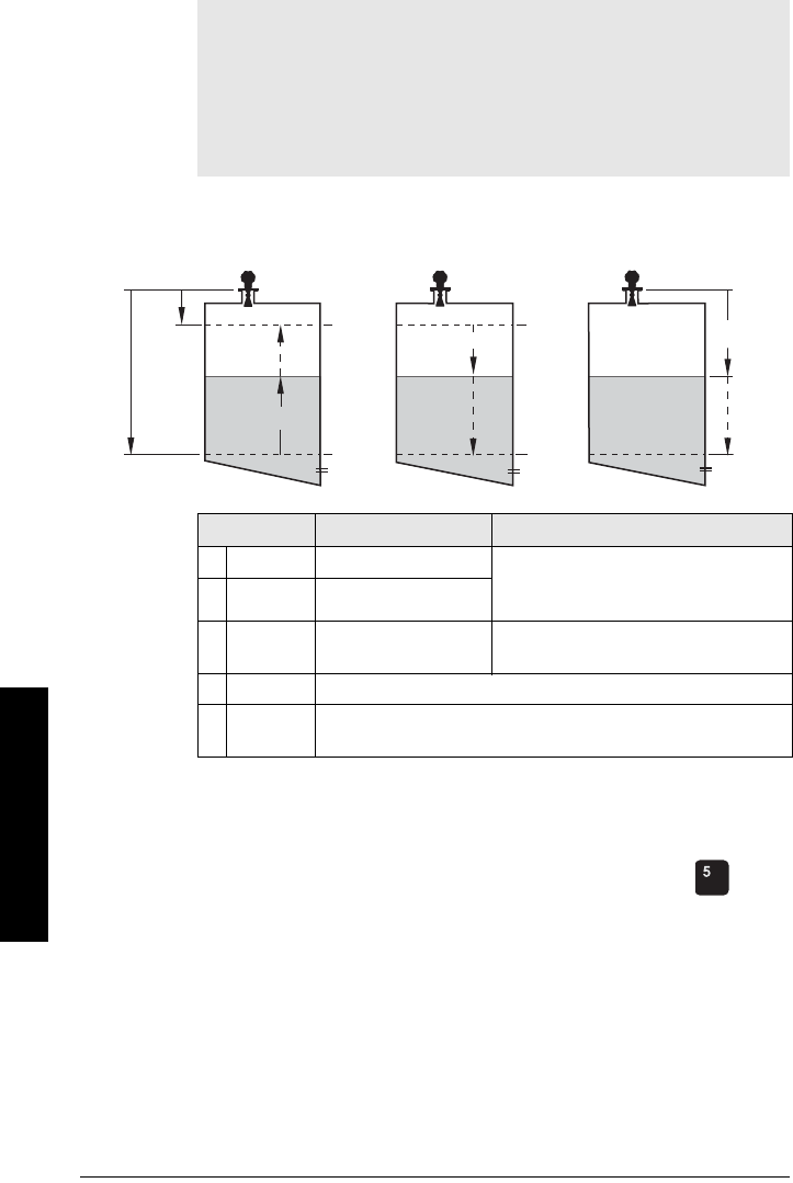
Page 84 SITRANS LR250 (HART) – INSTRUCTION MANUAL 7ML19985JE03
mmmmm
Parameters
2.6. Analog Output Scaling
2.6.1. Current Output Function
Can be set to either Level, Space, Distance, or Volume. (The device can carry
out a volume calculation only after a vessel shape has been specified.)
To view the mA reading in the secondary region of the LCD, press on the
handheld programmer.
To modify Current Output Function via SIMATIC PDM:
• Open the menu Device – Select Analog Output. (See
Select Analog Output
on page 55 for more detail.)
Notes:
•Level, space, and distance, have different reference points.
• Use caution when changing Current Output Function while the device is
connected to a HART network. Current Output Function controls the
primary value and the loop current for the device.
• Current Output Function also affects the secondary, tertiary and
quaternary variables in a HART network.
Options Reference point Description
* Level Low Calibration Point measured as a percentage of the
difference between High Calibration Point
and Low Calibration Point
Space High Calibration Point
Distance sensor reference point measured as a percentage of Low
Calibration Point
Volume converts a level measurement to a volume output
Manuala)
(LUI only)
a) Current Output Function must be set to Manual before modifying mA Output Value
(2.6.6.). Remember to restore the previous Current Output Function setting after
modifying mA Output Value.
allows mA Output Value (2.6.6.) to be set to a user-defined value
Level Space Distance
Distance
Space
Level
20 mA
100%
4 mA
0%
High
Cal.
Point
4 mA
0%
20 mA
100%
4 mA
0%
20 mA
100%
Sensor
ref.
pt.
Low
Cal.
Pt.

7ML19985JE03 SITRANS LR250 (HART) – INSTRUCTION MANUAL Page 85
mmmmm
Parameters
2.6.2. Start of Scale (4 mA Setpoint)
Sets the process level corresponding to the 4 mA value. 4 mA always defaults
to 0, and Current Output Function (2.6.1.) determines whether this is a Level,
Space, Distance, or Volume measurement. (See Current Output Function (2.6.1.)
for an illustration.)
• Enter the reading that is to correspond to a 4 mA output.
• Units are defined in Units (2.2.1.) for Level, Space, or Distance. Units are
unspecified for Volume.
2.6.3. Full Scale (20 mA Setpoint)
Sets the process level corresponding to the 20 mA value. 20 mA always defaults
to 100%, and Current Output Function (2.6.1.) determines whether this is a Level,
Space, or Distance measurement. (See Current Output Function (2.6.1.) for an
illustration.
)
• Enter the reading that is to correspond to a 20 mA output.
• Units are defined in Units (2.2.1.) for Level, Space, or Distance. Units are
unspecified for Volume
.
2.6.4. Control Range: lower limit (Min. mA limit)
Prevents the mA output from dropping below this minimum level for a
measurement value. This does not restrict the Fail-safe or Manual settings.
2.6.5. Control Range: upper limit (Max. mA limit)
Prevents the mA output from rising above this maximum level for a
measurement value. This does not restrict the Fail-safe or Manual settings.
Values
Range: –999999 to +999999
Default: 0.00 m (set to value corresponding to 0% as defined by
Current Output Function)
Related
Parameters
Units (2.2.1.)
Current Output Function (2.6.1.)
Values
Range: –999999 to +999999
Default: 20.00 m (set to value corresponding to 100% as defined by
Current Output Function)
Related
Parameters
Units (2.2.1.)
Current Output Function (2.6.1.)
Values Range: 3.8 to 20.5 (mA)
Default: 3.80 (mA)
Values Range: 3.8 to 20.5 (mA)
Default: 20.50 (mA)
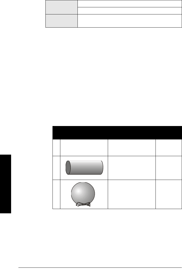
Page 86 SITRANS LR250 (HART) – INSTRUCTION MANUAL 7ML19985JE03
mmmmm
Parameters
2.6.6. mA Output Value
Allows you to use a simulated value to test the functioning of the loop.
You can
enter 4 mA, 20 mA, or any other user-defined value within the range.
a) First set Current Output Function (2.6.1.) to Manual.
b) Enter the desired mA value in mA Output Value.
c) After completing the test, remember to reset Current Output Function
(2.6.1.) to the previous setting.
Via SIMATIC PDM:
Open the menu Device – Loop Test. (For more detail, see
Loop Test
on page
56.)
2.7. Linearization
2.7.1. Volume
Carries out a volume conversion from a level value.
2.7.1.1. Vessel Shape
Defines the vessel shape and allows the LR250 to calculate volume instead
of level. If None is selected, no volume conversion is performed. Select the
vessel shape matching the monitored vessel or reservoir.
Values Range: 3.56 mA to 22.6 mA
Read Only unless Current Output Function (2.6.1.) is set to Manual.
Related
parameter Current Output Function (2.6.1.)
Vessel Shape LCD DISPLAY/
Description
Also
required
*None
NONE/
No volume calculation
required
N/A
CYLINDER/
Flat end horizontal cylinder
maximum
volume
SPHERE/
Sphere
maximum
volume
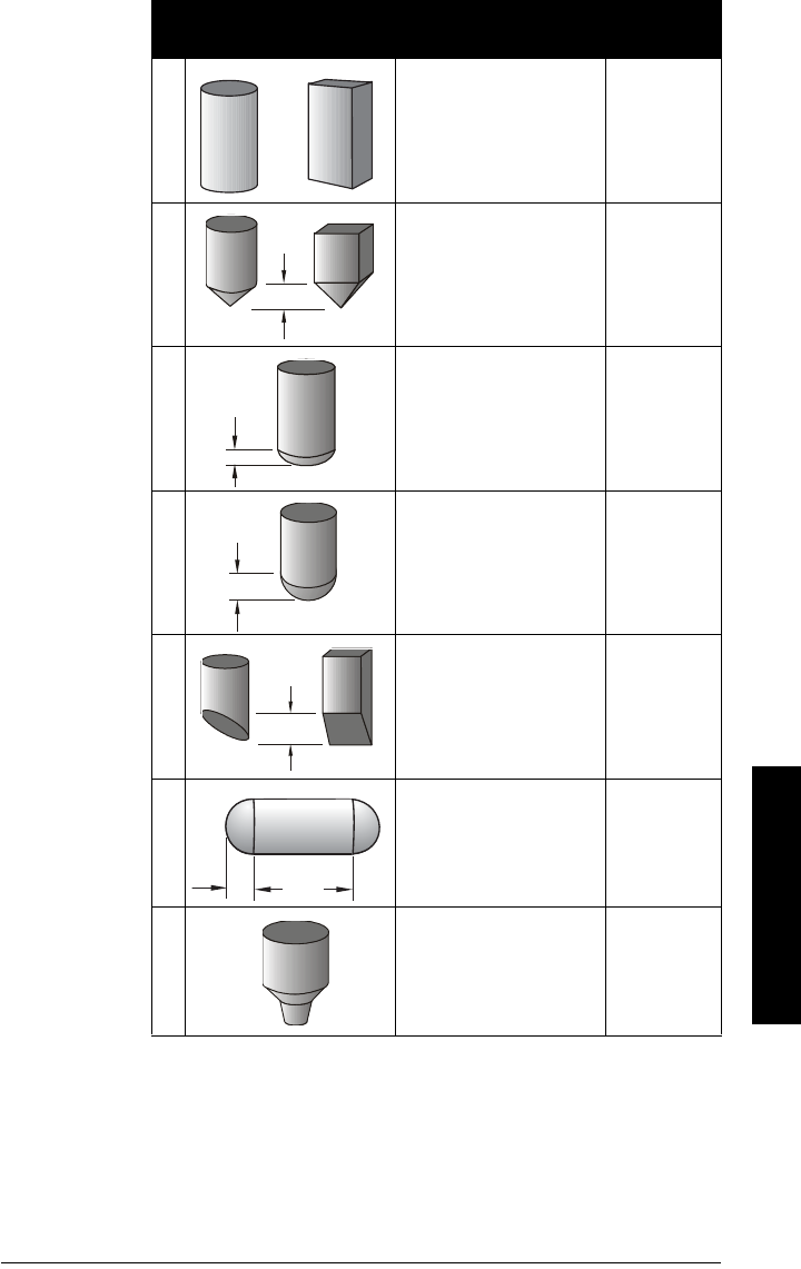
7ML19985JE03 SITRANS LR250 (HART) – INSTRUCTION MANUAL Page 87
mmmmm
Parameters
LINEAR/
Upright, linear (flat bottom)
maximum
volume
CONICAL BOT/
Conical or pyramidal bottom
maximum
volume,
dimension A
PARABOLIC BOT/Parabolic
bottom
maximum
volume,
dimension A
HALF SPHERE BOT/
Half-sphere bottom
maximum
volume,
dimension A
FLAT SLOPED BOT/
Flat sloped bottom
maximum
volume,
dimension A
PARABOLIC ENDS/
Parabolic end horizontal cyl-
inder
maximum
volume,
dimension A,
dimension L
LINEAR TABLEa)/
Linearization table
(level/volume breakpoints)
maximum
volume, tables
1-32 level and
volume break-
points
a) Linearization Table must be selected in order for level/volume values [see
Table 1-8 (2.7.2.)] to be transferred.
Vessel Shape
(cont’d)
LCD DISPLAY/
Description
Also
required
A
A
A
A
AL

Page 88 SITRANS LR250 (HART) – INSTRUCTION MANUAL 7ML19985JE03
mmmmm
Parameters
2.7.1.2. Maximum Volume
The maximum volume of the vessel. Enter the vessel volume corresponding
to High Calibration Point. For example, if your maximum vessel volume is
8000 L, enter a value of 8000. Volume units are defined by the user but are
not explicitly stated in the SITRANS LR250
2.7.1.3. Dimension A
The height of the vessel bottom when the bottom is conical, pyramidal,
parabolic, spherical, or flat -sloped. If the vessel is horizontal with parabolic
ends, the depth of the end. See Vessel Shape (2.7.1.1.) for an illustration.
2.7.1.4. Dimension L
Length of the cylindrical section of a horizontal parabolic end vessel. See
Vessel Shape (2.7.1.1.) for an illustration.
2.7.2. Table 1-8
If your vessel shape is more complex than any of the preconfigured shapes, you
can define the shape as a series of segments. A value is assigned to each level
breakpoint and a corresponding value is assigned to each volume breakpoint.
Level values are defined in Units (2.2.1.). Volume units are defined by the user
but are not explicitly stated in the SITRANS LR250.
Values Range: 0.0000 to 99999
Default: 100.0
Related Parameters
Low Calibration Pt. (2.3.1.)
High Calibration Pt. (2.3.2.)
Vessel Shape (2.7.1.1.)
Values Range: 0.0000 to 99999 mm
Default: 0.0
Related Parameters Units (1.4.)
Vesse l Sh ape (2 .7.1.1. )
Values Range: 0.0000 to 99999 mm
Default: 0.0
Related Parameters Units (1.4.)
Vesse l Sh ape (2 .7.1.1. )
Note: Linearization Table must be selected in Vesse l Shape (2.7.1.1. ) in order
for level/volume values to be transferred.
Level Values Range: 0.0000 to 99999 mm
Default: 0.0
Volume Values Range: 0.0000 to 99999
Default: 0.0
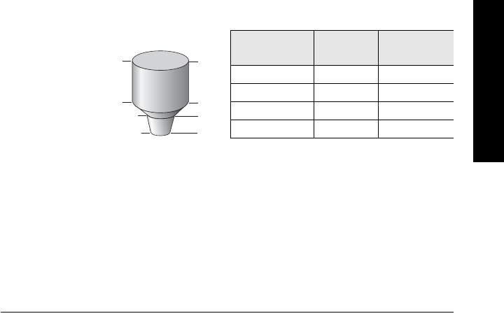
7ML19985JE03 SITRANS LR250 (HART) – INSTRUCTION MANUAL Page 89
mmmmm
Parameters
Enter up to 32 level breakpoints, where the corresponding volume is known.
The values corresponding to 100% and 0% levels must be entered. The
breakpoints can be ordered from top to bottom, or the reverse.
Breakpoints are grouped into four tables: Table 1-8, Table 9-16, Table 17-24, and
Table 25-32.
Entering breakpoints via SIMATIC PDM:
• See
Using Linearization via the Quick Start wizard
on page 45.
Entering breakpoints via the handheld programmer:
a) The default unit for level values is m: to change it navigate to Setup (2.) >
Sensor (2.2.) > Units (2.2.1.), and select the desired unit.
b) Navigate to Setup (2.) > Linearization (2.7.) > Maximum Volume (2.7.1.2.),
and enter the value.
c) Go to the appropriate table for the particular breakpoint you wish to adjust:
for example, go to Table 1-8 for breakpoint 1.
d) Under Table 1-8, go to Level 1 (2.7.2.1.) to enter the level value for the
breakpoint 1.
e) Under Table 1-8, go to Volume 1 (2.7.2.2.) to enter the volume value for the
breakpoint 1
f) Repeat steps c) to e), till values have been entered for all required
breakpoints.
2.7.2.1. Level 1
a) Press RIGHT arrow to open Edit mode.
b) Enter level value and press RIGHT arrow to accept it.
c) Press Down ARROW to move to corresponding volume breakpoint.
2.7.2.2. Volume 1
a) Press RIGHT arrow to open Edit mode.
b) Enter volume value and press RIGHT arrow to accept it.
c) Press Down ARROW to move to next level breakpoint.
Example (values are for example purposes only)
2.7.3. Table 9-16
2.7.4. Table 17-24
2.7.5. Table 25-32
419.5
9
5
0
Breakpoint
number
3
2
1
Breakpoint
Number
Level value
(m)
Volume
value (l)
100
25500
3 9 3000
4 19.5 8000
Level
value

Page 90 SITRANS LR250 (HART) – INSTRUCTION MANUAL 7ML19985JE03
mmmmm
Parameters
2.8. Signal Processing
2.8.1. Near Range
The range in front of the device (measured from the sensor reference point)
within which any echoes will be ignored. This is sometimes referred to as
blanking or a dead zone. The factory setting is 50 mm past the end of the horn,
and the range is dependent on the horn type.
2.8.2. Far Range
Allows the material level to drop below Low Calibration Point without
generating a Loss of Echo (LOE) state. See Sensor Mode (2.2.2.) on page 79 for
an illustration.
Use this feature if the measured surface can drop below the Low Cal. Point in
normal operation.
Note: Default settings in the parameter tables are indicated with an asterisk (*)
unless explicitly stated.
Values
Range: 0 to 20 m (0 to 65.6 ft)
Default depends on antenna.
Examples:
1.5" horn 0.185 m (7.28")
4" horn with 100 mm extension 0.270 m (10.62")
Related
parameters Units (1.4.)
Values
Range: Min. = Low Calibration Pt.
Max. = 23 m (75.45 ft)
Default: Value for Low Calibration Pt. + 1 m (3.28 ft)
Related
parameters Units (1.4.)
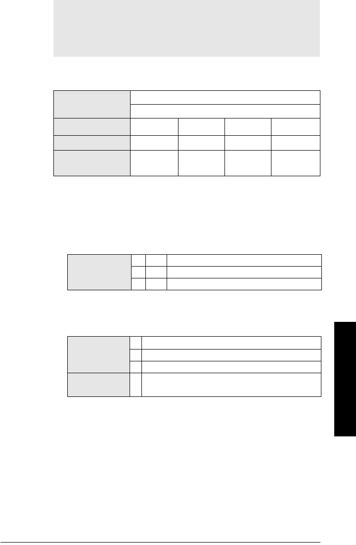
7ML19985JE03 SITRANS LR250 (HART) – INSTRUCTION MANUAL Page 91
mmmmm
Parameters
2.8.3. Propagation Factor
Compensates for the change in microwave velocity due to propagation within
a metal stillpipe instead of in free space.
2.8.4. Echo select
2.8.4.1. Algorithm
Selects the algorithm to be applied to the echo profile to extract the true
echo.
2.8.4.2. Position Detect
Defines where on the echo the distance measurement is determined.
See
Position Detect (2.8.4.2.)
on page 127 for more detail.
If the vessel bottom is being reported as the level instead of the actual
material level (at low level conditions), or if the dielectric constant of the
liquid to be monitored is less than 3, we recommend setting Position to
Hybrid and CLEF Range (2.8.4.4.) to 0.5 m (1.64 ft).
Notes:
• When operating in a stillpipe, values for CLEF Range (2.8.4.4.) on page 92,
and for the propagation factor, should be set according to the pipe size.
See the table below.
• For reliable results the horn size must be close to the pipe size.
Values Range: 0.3 to 1.5 depending on pipe size.
Default: 1.0000
Nominal Pipe Sizea)
a) Since pipe dimensions may vary slightly, the propagation factor may also vary.
40 mm (1.5”) 50 mm (2”) 80 mm (3”) 100 mm (4”)
Propagation Factor 0.9828 0.990 0.991 0.9965
CLEF Range
(2.8.4.4.) settings
Low Cal Pt. –
700 mm
Low Cal Pt. –
700 mm
Low Cal Pt. –
1000 mm
Low Cal Pt. –
1000 mm
Options
*tFtrue First echo
LLargest echo
BLF Best of First or Largest echo
Options
Center
* Hybrid (Center and CLEF)
CLEF (Constrained Leading Edge Fit)
Related
parameters CLEF Range (2.8.4.4.)

Page 92 SITRANS LR250 (HART) – INSTRUCTION MANUAL 7ML19985JE03
mmmmm
Parameters
2.8.4.3. Echo Threshold
Sets the minimum echo confidence that the echo must meet in order to
prevent a Loss of Echo condition and the expiration of the Fail-safe (LOE)
timer. When Confidence (2.8.6.1.) exceeds Echo Threshold (2.8.4.3.), the
echo is accepted as a valid echo and is evaluated.
Use this feature when an incorrect material level is reported.
2.8.4.4. CLEF Range
Used mainly to allow correct level reporting for low dK materials which may
otherwise cause an incorrect reading in an empty or almost empty vessel.
CLEF range is the level below which the CLEF algorithm is used when
Hybrid is selected in Position Detect (2.8.4.2.). Above that point the Center
algorithm is used. For more detail see Position Detect (2.8.4.2.)
on page
127
).
In applications with low dK materials we recommend setting CLEF Range
to 0.5 m (1.64 ft) and Position Detect (2.8.4.2.) to Hybrid.
2.8.5. Sampling
Provides a method of checking the reliability of a new echo before accepting it
as the valid reading, based on numbers of samples above or below the
currently selected echo.
2.8.5.1. Echo Lock
Selects the measurement verification process.
For radar applications, Material Agitator is the most often-used setting, to
avoid agitator blade detection.
Values Range: 0 to 99
Default: 5
Related
Parameters Timer (2.5.2.)
Values Range: 0 to 20 m (0 to 65.6 ft)
Default: 0.00 m
Related
parameters Position Detect (2.8.4.2.)
Note: Ensure the agitator is always running while SITRANS LR250
is monitoring the vessel, to avoid stationary blade detection.
Options
Lock Off
Maximum Verification (not recommended for radar)
*Material Agitator
Total Lock (not recommended for radar)
Related
parameters
Fill Rate (2.4.2.)
Empty rate (2.4.3.)
Sampling Up (2.8.5.2.)
Sampling Down (2.8.5.3.)
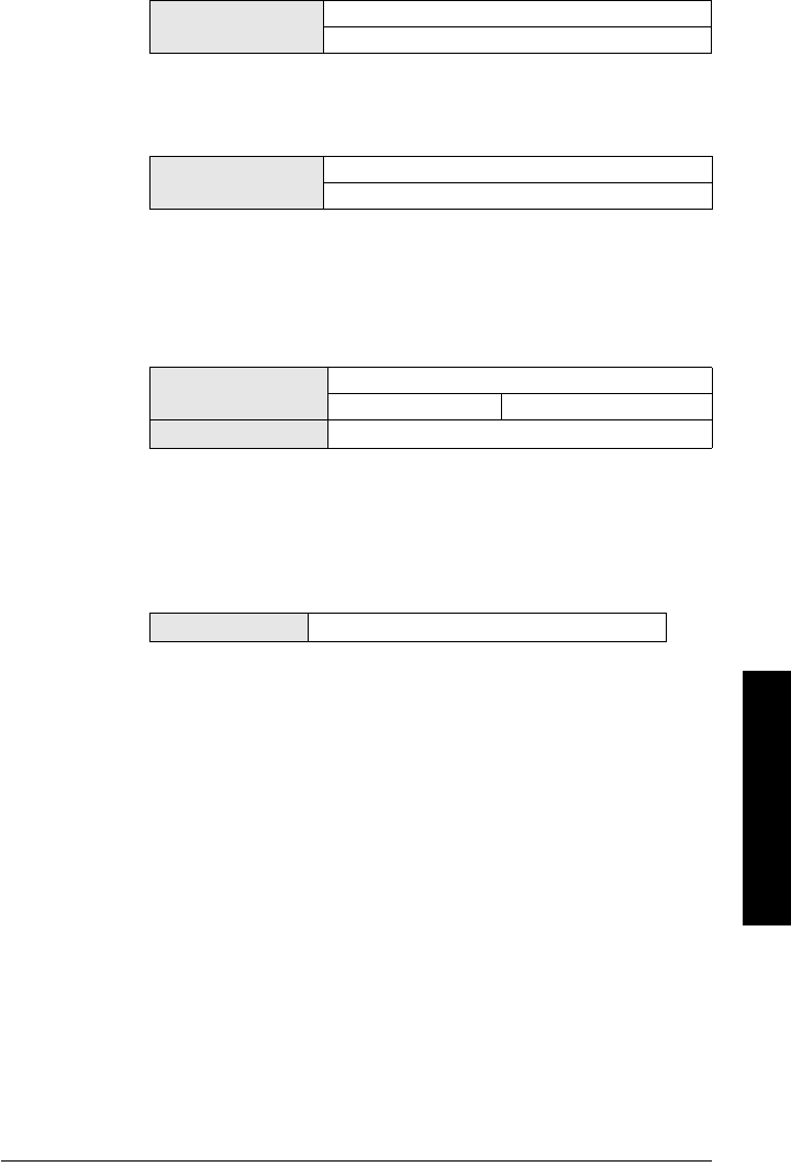
7ML19985JE03 SITRANS LR250 (HART) – INSTRUCTION MANUAL Page 93
mmmmm
Parameters
2.8.5.2. Sampling Up
Specifies the number of consecutive echoes that must appear above the
echo currently selected, before the measurement is accepted as valid.
2.8.5.3. Sampling Down
Specifies the number of consecutive echoes that must appear below the
echo currently selected, before the measurement is accepted as valid.
2.8.6. Echo Quality
2.8.6.1. Confidence
Indicates echo reliability: higher values represent better echo quality. The
display shows the echo confidence of the last measurement. Echo
Threshold (2.8.4.3.) defines the minimum criterion for echo confidence.
Open the menu Device – Echo Profile Utilities and click on the tab Echo
Profile.
2.8.6.2. Echo Strength
Displays the absolute strength (in dB above 1 µV rms) of the echo selected
as the measurement echo.
Open the menu Device – Echo Profile Utilities and click on the tab Echo
Profile.
2.8.6.3. Noise Average
Displays the average ambient noise (in dB above 1 µV rms) of a noise
profile. Noise level is a combination of transient noise and receiving
circuitry. After a measurement, the values from the previous noise shot will
be displayed.
Values Range: 1 to 50
Default: 5
Values Range: 1 to 50
Default: 2
Values (view only) 0 to 99
---- Shot not used
Related Parameters Echo Threshold (2.8.4.3.)
Values (view only) –20 to 99
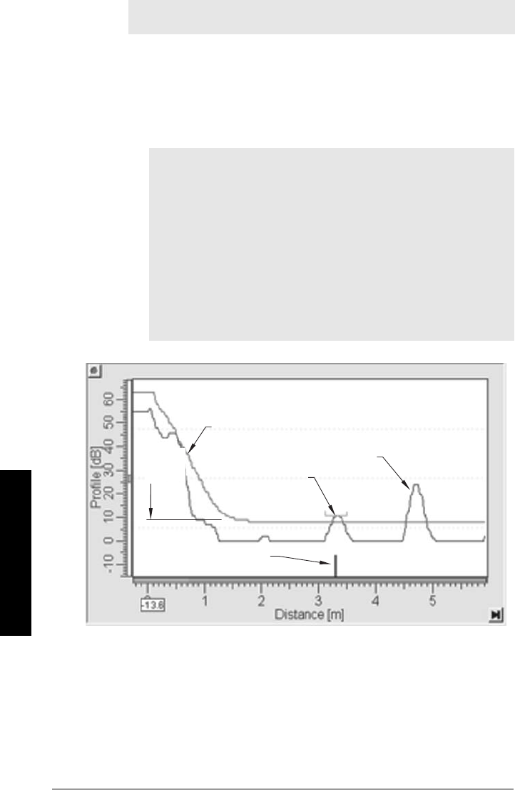
Page 94 SITRANS LR250 (HART) – INSTRUCTION MANUAL 7ML19985JE03
mmmmm
Parameters
2.8.7. TVT setup
2.8.7.1. Auto False Echo Suppression
Used together with Auto False Echo Suppression Range (2.8.7.2.) to screen
out false echoes in a vessel with known obstructions.
A ’learned TVT’ (time
varying threshold) replaces the default TVT over a specified range. See
Auto False Echo Suppression (2.8.7.1.) on page 130 for a more detailed
explanation.
a) Determine Auto False Echo Suppression Range. Measure the actual
distance from the sensor reference point to the material surface
using a rope or tape measure.
b) Subtract 0.5 m (20") from this distance, and use the resulting value.
Note: Default settings in the parameter tables are indicated with an asterisk
(*) unless explicitly stated.
Notes:
• Make sure material level is below all known obstructions when Auto
False Echo Suppression is used to learn the echo profile. (An empty or
almost empty vessel is recommended.)
• Note the distance to material level when Auto False Echo learns the
environment. Set Auto False Echo Suppression Range to a shorter
distance to avoid the material echo being screened out.
• Set Auto False Echo Suppression and Auto False Echo Suppression
Range during startup, if possible.
• If the vessel contains an agitator it should be running.
• Before adjusting these parameters, rotate the instrument for best
signal (lower false-echo amplitude).
Before Auto False Echo Suppression
default TVT
TVT
Hover
Level
Level (db)
echo marker
material level
false echo
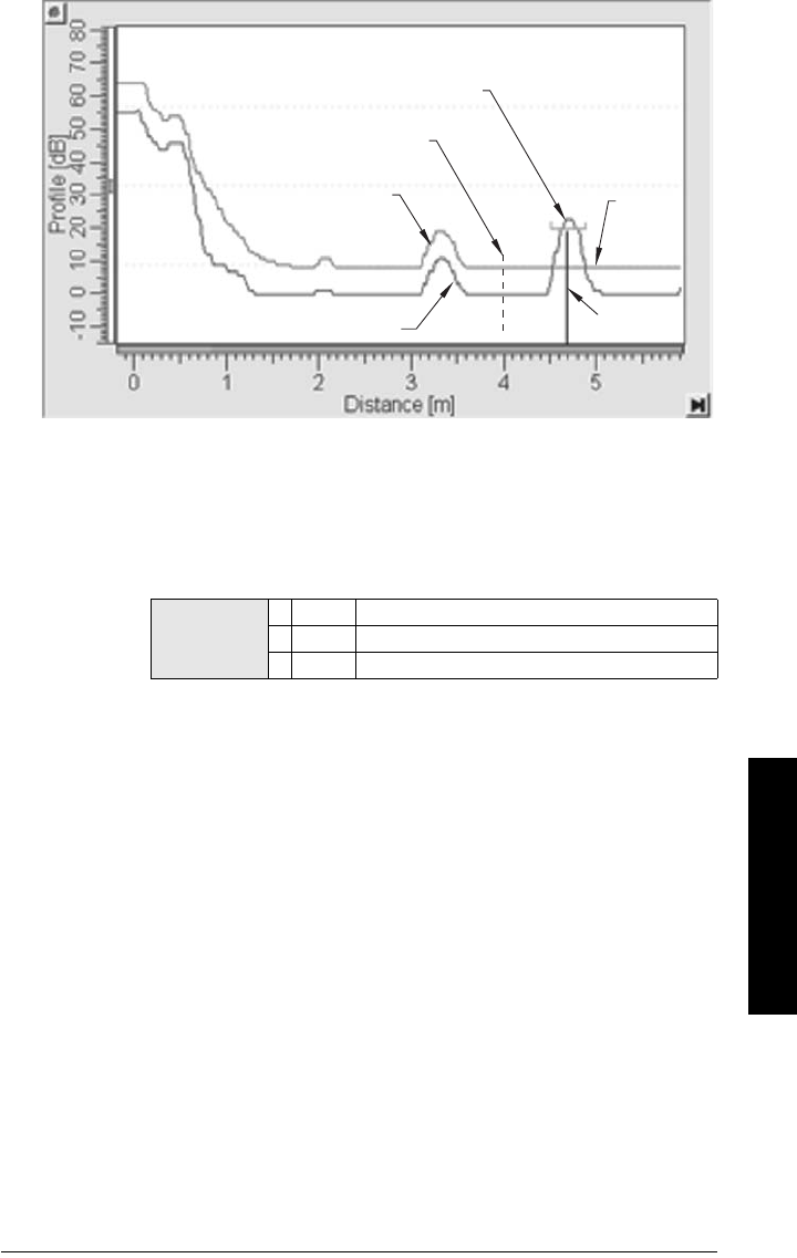
7ML19985JE03 SITRANS LR250 (HART) – INSTRUCTION MANUAL Page 95
mmmmm
Parameters
To set Auto False Echo Suppression via SIMATIC PDM:
Open the menu Device – Echo Profile Utilities and click on the tab Auto
False Echo Suppression.
(For more detailed instructions see
Auto False Echo Suppression
on page
52.)
To set Auto False Echo Suppression via the handheld programmer:
c) Go to Auto False Echo Suppression Range (2.8.7.2.) and enter the
value calculated in step b).
d) Go to Auto False Echo Suppression (2.8.7.1.) and press RIGHT arrow
to open Edit Mode
e) Select Learn. The device will automatically revert to On (Use
Learned TVT) after a few seconds.
Options
OFF Default TVT will be used.
* ON ’Learned’ TVT will be used.
LEARN ’Learn’ the TVT.
After Auto False Echo Suppression
learned TVT
material level
false echo
Auto False Echo Suppression
Range
echo
marker
Level (db)
default
TVT

Page 96 SITRANS LR250 (HART) – INSTRUCTION MANUAL 7ML19985JE03
mmmmm
Parameters
2.8.7.2. Auto False Echo Suppression Range
Specifies the range within which Learned TVT is used (see Auto False Echo
Suppression (2.8.7.1.) on page 130 for more detail).
a) Calculate range according to Auto False Echo Suppression (2.8.7.1.)
steps a) and b).
b) Press RIGHT arrow to open Edit mode.
c) Enter the new value and press RIGHT arrow to accept it.
d) Set Auto False Echo Suppression (2.8.7.1.).
2.8.7.3. Hover Level
Defines how high the TVT (Time Varying Threshold) is placed above the
noise floor of the echo profile, as a percentage of the difference between
the peak of the largest echo in the profile and the noise floor. See Before
Auto False Echo Suppression on page 94 for an illustration.
When the device is located in the center of the vessel, the TVT hover level
may be lowered to increase the confidence level of the largest echo.
2.8.7.4. Shaper Mode
Enables/disables the TVT shaper.
2.8.8. TVT shaper
Adjusts the TVT (Time Varying Threshold) at a specified range (breakpoint on
the TVT). This allows you to reshape the TVT to avoid unwanted echoes. There
are 40 breakpoints arranged in 5 groups. (We recommend using SIMATIC PDM
to access this feature.)
Values Range: 0.00 to 20.00 m
Default: 1.0 0 m
Related parameters Units (1.4.)
Values Range: 0 to 100%
Default: 40%
Options ON
*OFF
Notes:
• The range is –100 to 100 bits. With 2 bits per dB this gives a range of –50 to
50 dB.
•Shaper Mode (2.8.7.4.) must be turned ON in order for TVT shaper points to
be transferred

7ML19985JE03 SITRANS LR250 (HART) – INSTRUCTION MANUAL Page 97
mmmmm
Parameters
To use TVT shaper via SIMATIC PDM:
a) Go to Level Meter > Setup > Signal Processing > TVT setup > Shaper
Mode and select On.
b) Open the menu Device – Echo Profile Utilities and click on TVT Shaper. For
more detail see page 51.
To use TVT shaper via LUI (local user interface):
a) Go to Shaper Mode (2.8.7.4.) and select On.
b) Go to TVT Breakpoint 1-9 (2.8.8.1.).
c) Open Shaper 1 and enter the TVT Offset value (between –50 and 50).
d) Go to the next Shaper point and repeat steps c) and d) till all desired
breakpoint values have been entered.
2.8.8.1. TVT Breakpoint 1-9
2.8.8.2. TVT Breakpoint 10-18
2.8.8.3. TVT Breakpoint 19-27
2.8.8.4. TVT Breakpoint 28-36
2.8.8.5. TVT Breakpoint 37-40
2.8.9. Measured Values
Read only. Allows you to view measured values for diagnostic purposes
To access measured values via SIMATIC PDM:
Open the menu View – Process Variables.
2.8.9.1. Level Measurement
The value for level.
2.8.9.2. Space Measurement
The value for space.
2.8.9.3. Distance Measurement
The value for distance.
2.8.9.4. Volume Measurement
The value for volume.
Values Range: –50 to 50 dB
Default: 0 dB
Values Range: –50 to 50 dB
Default: 0 dB
Values Range: –50 to 50 dB
Default: 0 dB
Values Range: –50 to 50 dB
Default: 0 dB
Values Range: –50 to 50 dB
Default: 0 dB

Page 98 SITRANS LR250 (HART) – INSTRUCTION MANUAL 7ML19985JE03
mmmmm
Parameters
3. Diagnostics
3.1. Echo Profile
Allows you to request the current echo profile either locally via the handheld
programmer, or remotely via SIMATIC PDM, or AMS Device Manager. (For more
detail see Echo Processing on page 126.)
To request a profile via SIMATIC PDM open the menu Device – Echo Profile Utilities.
(For more detail see
Echo Profile Utilities
on page 49.)
To request a profile via the handheld programmer:
a) In PROGRAM mode, navigate to LEVEL METER > DIAGNOSTICS (3) > ECHO
PROFILE (3.1)
b) Press RIGHT arrow to request a profile.
(For more detail see
Requesting an Echo Profile
on page 38.)
3.2. Electronics Temperature
3.2.1. Current Internal Temperature
Read only. Displays (in degrees C) the current temperature on the circuit board
recorded by the internal electronics.
For access via SIMATIC PDM open the menu View – Process Variables and
check the field Electronics Temperature.
3.2.2. Highest value
Read only. Displays (in degrees C) the maximum temperature recorded by the
internal electronics. The high and low values are maintained over a power
cycle.
Via SIMATIC PDM navigate to Maintenance and Diagnostics > Electronics
Temperature.
3.2.3. Lowest value
Read only. Displays (in degrees C) the minimum temperature recorded by the
internal electronics. The high and low values are maintained over a power
cycle.
Via SIMATIC PDM navigate to Maintenance and Diagnostics > Electronics
Temperature.

7ML19985JE03 SITRANS LR250 (HART) – INSTRUCTION MANUAL Page 99
mmmmm
Parameters
4. Service
4.1. Master Reset
Resets all parameter to factory defaults, with the following exceptions:
•Device Address (5.1.) remains unchanged.
•Write Protect (6.2.1.) and PIN to Unlock (6.2.2.) values are not reset.
•Auto False Echo Suppression (2.8.7.1.) learned TVT is not lost.
To perform a reset to factory defaults via SIMATIC PDM, open the menu Device –
Master Reset and click on Factory Defaults.
4.2. Remaining Device Lifetime
The device tracks itself based on operating hours and monitors its predicted lifetime.
You can modify the expected device lifetime, set up schedules for maintenance
reminders, and acknowledge them.
The maintenance warnings and reminders are available through HART
communications. This information can be integrated into an Asset Management
system. For optimal use, we recommend that you use SIMATIC PCS7 Asset
Management Software in conjunction with SIMATIC PDM.
To access these parameters via SIMATIC PDM:
• Open the menu Device – Maintenance and select the Remaining Device Lifetime
tab.
• After modifying values/units as required, click on Write to accept the change,
and Read to view the effect of the change.
• Click on Snooze to add a year to the Total Expected Device Life.
Note: Default settings in the parameter tables are indicated with an asterisk (*) unless
explicitly stated.
Note: Following a reset to Factory Defaults, complete reprogramming is required.
Options *Idle or Done (Return to previous menu)
Factory Defaults
Notes:
• Default settings in the parameter tables are indicated with an asterisk (*) unless
explicitly stated.
• Four sets of parameters allow you to monitor the Device/Sensor Lifetimes and
set up Maintenance/Service schedules, based on operating hours instead of a
calendar-based schedule. See also Remaining Sensor Lifetime (4.3.), Service
Schedule (4.4.), and Calibration Schedule (4.5.).
• Performing a reset to Factory Defaults will reset all the Maintenance Schedule
parameters to their factory defaults.
• The device operates in years. To view Remaining Device Lifetime parameters in
hours or days (via SIMATIC PDM only) see Lifetime Expected (4.2.1.).
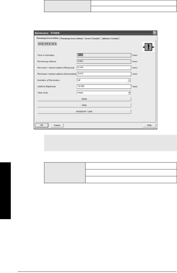
Page 100 SITRANS LR250 (HART) – INSTRUCTION MANUAL 7ML19985JE03
mmmmm
Parameters
Time Units
4.2.1. Lifetime Expected
Allows you to override the factory default.
4.2.2. Time in Operation
Read only. The amount of time the device has been operating.
4.2.3. Remaining Lifetime
Read only. Lifetime Expected (4.2.1.) less Time in Operation (4.2.2.).
Optionsa)
a) Selectable only via SIMATIC PDM.
Hours; days; years
Default: years
Note: The device always operates in years. Changing the units affects only
the parameter view of the Remaining Device Lifetime parameters in
SIMATIC PDM.
Values
Unitsa): hours, days, years
a) Units are selectable only via SIMATIC PDM.
Range: 0 to 20 years
Default: 10.00 years

7ML19985JE03 SITRANS LR250 (HART) – INSTRUCTION MANUAL Page 101
mmmmm
Parameters
4.2.4. Reminder Activation
Allows you to enable a maintenance reminder.
a) First set the values in Reminder 1 (Required) (4.2.5.)/Reminder 2
(Demanded) (4.2.6.).
b) Select the desired Reminder Activation option.
4.2.5. Reminder 1 (Required)
If Remaining Lifetime (4.2.3.) is equal to or less than this value, the device
generates a Maintenance Required reminder.
a) Modify values as required.
b) Set Reminder Activation (4.2.4.) to the desired option.
4.2.6. Reminder 2 (Demanded)
If Remaining Lifetime (4.2.3.) is equal to or less than this value, the device
generates a Maintenance Demanded reminder.
a) Modify values as required.
b) Set Reminder Activation (4.2.4.) to the desired option.
4.2.7. Maintenance Status
Indicates which level of maintenance reminder is active.
In SIMATIC PDM, open the menu View – Device Status, click on the
Maintenance tab, and check the Device Lifetime Status window.
Note: To modify this parameter via SIMATIC PDM it must be accessed via the
pull-down menu Device – Maintenance.
Options
Reminder 1 (Maintenance Required)
Reminder 2 (Maintenance Demanded)
Reminders 1 and 2
*OFF
Values Range: 0 to 20 years
Default: 0.164 years
Values Range: 0 to 20 years
Default: 0.019 years

Page 102 SITRANS LR250 (HART) – INSTRUCTION MANUAL 7ML19985JE03
mmmmm
Parameters
4.2.8. Acknowledge Status
Indicates which level of maintenance reminder has been acknowledged.
In SIMATIC PDM, open the menu View – Device Status, click on the
Maintenance tab, and check the Device Lifetime Status window.
4.2.9. Acknowledge
Acknowledges the current maintenance reminder.
To acknowledge a reminder via SIMATIC PDM:
a) Open the menu View – Device Status and click on the tab Maintenance.
b) In the Device Lifetime section, click on Acknowledge Warnings.
To acknowledge a reminder via the handheld programmer:
a) Press RIGHT arrow twice to open parameter view and activate Edit
Mode.
b) Press RIGHT arrow to acknowledge the reminder.
4.3. Remaining Sensor Lifetime
The device monitors the predicted lifetime of the sensor (the components exposed to
the vessel environment). You can modify the expected sensor lifetime, set up schedules
for maintenance reminders, and acknowledge them.
To access these parameters via SIMATIC PDM:
• Open the menu Device – Maintenance and select the Remaining Sensor
Lifetime tab.
• After modifying values/units as required, click on Write to accept the change,
and Read to view the effect of the change.
•Click on Snooze to add a year to the Total Expected Sensor Life.
•Click on Sensor Replaced to restart the timer and clear any fault messages.
Notes:
• Default settings in the parameter tables are indicated with an asterisk (*) unless
explicitly stated.
• Four sets of parameters allow you to monitor the Device/Sensor Lifetimes and
set up Maintenance/Service schedules, based on operating hours instead of a
calendar-based schedule. See also Remaining Device Lifetime (4.2.), Service
Schedule (4.4.), and Calibration Schedule (4.5.).
• Performing a reset to Factory Defaults will reset all the Maintenance Schedule
parameters to their factory defaults.
• The device operates in years. To view Remaining Sensor Lifetime parameters in
hours or days (via SIMATIC PDM only) see Lifetime Expected (4.3.1.).
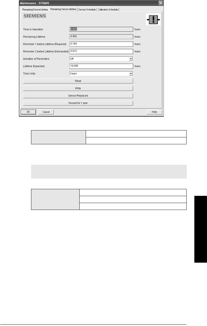
7ML19985JE03 SITRANS LR250 (HART) – INSTRUCTION MANUAL Page 103
mmmmm
Parameters
Time Units
4.3.1. Lifetime Expected
Allows you to override the factory default.
4.3.2. Time in Operation
The amount of time the sensor has been operating. Can be reset to zero after
performing a service or replacing the sensor.
To reset to zero:
• In SIMATIC PDM, open the menu Device – Maintenance, click on the
Remaining Sensor Lifetime tab, and click on Sensor Replaced to restart
the timer and clear any fault messages.
• Via the handheld programmer, manually reset Time in Operation (4.3.2.) to
zero.
Optionsa)
a) Selectable only via SIMATIC PDM.
Hours; days; years
Default: years
Note: The device always operates in years. Changing the units affects only
the parameter view of Remaining Sensor Life parameters in SIMATIC PDM.
Values
Unitsa): hours, days, years
a) Units are selectable only via SIMATIC PDM.
Range: 0 to 20 years
Default: 10.00 years

Page 104 SITRANS LR250 (HART) – INSTRUCTION MANUAL 7ML19985JE03
mmmmm
Parameters
4.3.3. Remaining Lifetime
Read only. Lifetime Expected (4.3.1.) less Time in Operation (4.3.2.).
4.3.4. Reminder Activation
Allows you to enable a maintenance reminder
.
a) First set the values in Reminder 1 (Required) (4.3.5.)/Reminder 2
(Demanded) (4.3.6.).
b) Select the desired Reminder Activation option.
4.3.5. Reminder 1 (Required)
If Remaining Lifetime (4.3.3.) is equal to or less than this value, the device
generates a Maintenance Required reminder.
a) Modify values as required.
b) Set Reminder Activation (4.3.4.) to the desired option.
4.3.6. Reminder 2 (Demanded)
If Remaining Lifetime (4.3.3.) is equal to or less than this value, the device
generates a Maintenance Demanded reminder.
a) Modify values as required.
b) Set Reminder Activation (4.3.4.) to the desired option.
4.3.7. Maintenance Status
Indicates which level of maintenance reminder is active.
In SIMATIC PDM, open the menu View – Device Status, click on the
Maintenance tab, and check the Sensor Lifetime Status window.
Note: To modify this parameter via SIMATIC PDM it must be accessed via the
pull-down menu Device – Maintenance.
Options
Reminder 1 (Maintenance Required)
Reminder 2 (Maintenance Demanded)
Reminders 1 and 2
*OFF
Values Range: 0 to 20 years
Default: 0.164 years
Values Range: 0 to 20 years
Default: 0.019 years

7ML19985JE03 SITRANS LR250 (HART) – INSTRUCTION MANUAL Page 105
mmmmm
Parameters
4.3.8. Acknowledge Status
Indicates which level of maintenance reminder has been acknowledged.
In SIMATIC PDM, open the menu View – Device Status, click on the
Maintenance tab and check the Sensor Lifetime Status window.
4.3.9. Acknowledge
Acknowledges the current maintenance reminder.
To acknowledge a reminder via SIMATIC PDM:
a) Open the menu View – Device Status and click on the Maintenance tab.
b) In the Sensor Lifetime section click on Acknowledge Warnings.
To acknowledge a reminder via the handheld programmer:
a) Press RIGHT arrow twice to open parameter view and activate Edit
Mode.
b) Press RIGHT arrow to acknowledge the reminder.
4.4. Service Schedule
The device tracks service intervals based on operating hours and monitors the
predicted lifetime to the next service. You can modify the Total Service Interval, set
schedules for maintenance reminders, and acknowledge them.
The maintenance warnings and reminders are communicated to the end user
through status information. This information can be integrated into any Asset
Management system. For optimal use, we recommend that you use SIMATIC PCS7
Asset Management Software in conjunction with SIMATIC PDM.
To access these parameters via SIMATIC PDM:
• Open the menu Device – Maintenance and select the Service Schedule tab.
• After modifying values/units as required, click on Write to accept the change,
and Read to view the effect of the change.
•Click on Service Performed to restart the timer and clear any fault messages.
(see next page for an illustration)
Notes:
• Four sets of parameters allow you to monitor the Device/Sensor Lifetimes and
set up Maintenance/Service schedules, based on operating hours instead of a
calendar-based schedule. See also Remaining Device Lifetime (4.2.), Remaining
Sensor Lifetime (4.3.), and Calibration Schedule (4.5.).
• Performing a reset to Factory Defaults will reset all the Maintenance Schedule
parameters to their factory defaults.
• The device operates in years. To view Service Interval parameters in hours or
days (via SIMATIC PDM only) see Service interval (4.4.1.).
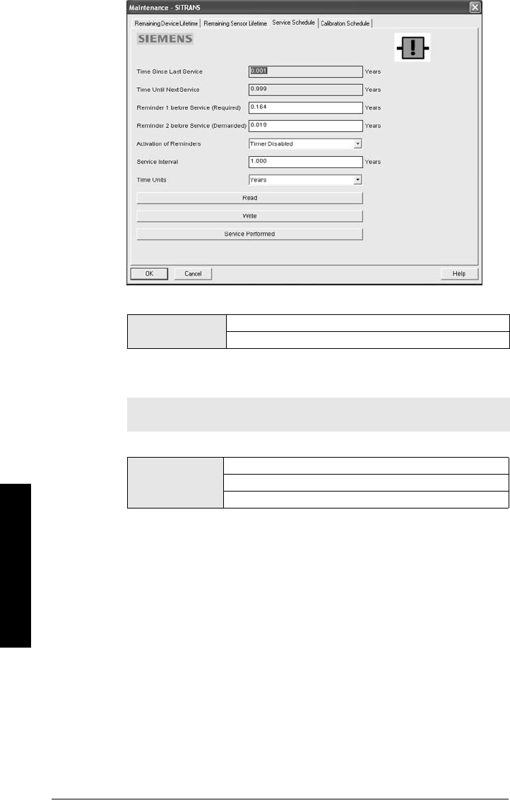
Page 106 SITRANS LR250 (HART) – INSTRUCTION MANUAL 7ML19985JE03
mmmmm
Parameters
Time Units
4.4.1. Service interval
User-configurable recommended time between product inspections
.
4.4.2. Time since Last Service
Time elapsed since last service. Can be reset to zero after performing a service.
To reset to zero:
• In SIMATIC PDM, open the menu Device – Maintenance, click on the
Service Schedule tab, and click on Service Performed to restart the timer
and clear any fault messages.
• Via the handheld programmer, manually reset Time since Last Service
(4.4.2.) to zero.
Optionsa)
a) Selectable only via SIMATIC PDM.
Hours; days; years
Default: years
Note: The device always operates in years. Changing the units affects only
the parameter view of the Service Interval parameters in SIMATIC PDM.
Values
Unitsa): hours, days, years
a) Units are selectable only via SIMATIC PDM.
Range: 0 to 20 years
Default: 1.0 year
7ML19985JE03 SITRANS LR250 (HART) – INSTRUCTION MANUAL Page 107
mmmmm
Parameters
4.4.3. Time until Next Service
Read only. Service interval (4.4.1.) less Time since Last Service (4.4.2.).
4.4.4. Reminder Activation
Allows you to enable a maintenance reminder.
a) First set the values in Reminder 1 (Required) (4.4.5.)/Reminder 2
(Demanded) (4.4.6.).
b) Select the desired Reminder Activation option.
4.4.5. Reminder 1 (Required)
If Time until Next Service (4.4.3.) is equal to or less than this value, the device
generates a Maintenance Required reminder.
a) Modify values as required.
b) Set Reminder Activation (4.4.4.) to the desired option.
4.4.6. Reminder 2 (Demanded)
If Time until Next Service (4.4.3.) is equal to or less than this value, the device
generates a Maintenance Demanded reminder.
a) Modify values as required.
b) Set Reminder Activation (4.4.4.) to the desired option.
4.4.7. Maintenance Status
Indicates which level of maintenance reminder is active.
Open the menu View – Device Status, click on the Maintenance tab and check
the Service Schedule Status window.
Note: To modify this parameter via SIMATIC PDM it must be accessed via the
pull-down menu Device – Maintenance.
Values
* Timer OFF
ON - no reminders checked
ON - Reminder 1 (Maintenance Required) checked
ON - Reminders 1 and 2 checked
ON - Reminder 2 (Maintenance Demanded) checked
Values Range: 0 to 20 years
Default: 0.164 years
Values Range: 0 to 20 years
Default: 0.019 years

Page 108 SITRANS LR250 (HART) – INSTRUCTION MANUAL 7ML19985JE03
mmmmm
Parameters
4.4.8. Acknowledge Status
Indicates which level of maintenance reminder has been acknowledged.
Open the menu View – Device Status, click on the Maintenance tab and check
the Service Schedule Status window.
4.4.9. Acknowledge
Acknowledges the current maintenance reminder.
To acknowledge a reminder via SIMATIC PDM:
a) Open the menu View – Device Status and click on the Maintenance tab.
b) In the Service Schedule Status section click on Acknowledge Warnings.
To acknowledge a reminder via the handheld programmer:
a) Press RIGHT arrow twice to open parameter view and activate Edit
Mode.
b) Press RIGHT arrow to acknowledge the reminder.
4.5. Calibration Schedule
The device tracks calibration intervals based on operating hours and monitors the
predicted lifetime to the next calibration. You can modify the Total Calibration Interval,
set schedules for maintenance reminders, and acknowledge them.
To access these parameters via SIMATIC PDM:
• Open the menu Device – Maintenance and select the Calibration Schedule tab.
• After modifying values/units as required, click on Write to accept the change,
and Read to view the effect of the change.
•Click on Calibration Performed to restart the timer and clear any fault
messages.
Notes:
• Default settings in the parameter tables are indicated with an asterisk (*) unless
explicitly stated.
• Four sets of parameters allow you to monitor the Device/Sensor Lifetimes and
set up Maintenance/Service schedules, based on operating hours instead of a
calendar-based schedule. See also Remaining Device Lifetime (4.2.), Remaining
Sensor Lifetime (4.3.), and Service Schedule (4.4.).
• Performing a reset to Factory Defaults will reset all the Maintenance Schedule
parameters to their factory defaults.
• The device operates in years. To view Calibration Interval parameters in hours or
days (via SIMATIC PDM only) see Calibration Interval (4.5.1.).
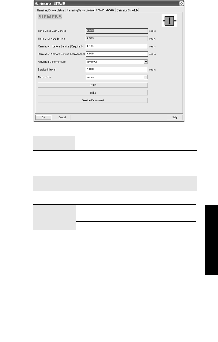
7ML19985JE03 SITRANS LR250 (HART) – INSTRUCTION MANUAL Page 109
mmmmm
Parameters
Time Units
4.5.1. Calibration Interval
User-configurable recommended time between product calibrations.
Optionsa)
a) Selectable only via SIMATIC PDM.
Hours; days; years
Default: years
Note: The device always operates in years. Changing the units affects only
the parameter view of the Calibration Interval parameters in SIMATIC PDM.
Values
Unitsa): hours, days, years
a) Units are selectable only via SIMATIC PDM.
Range: 0 to 20 years
Default: 1.0 year

Page 110 SITRANS LR250 (HART) – INSTRUCTION MANUAL 7ML19985JE03
mmmmm
Parameters
4.5.2. Time since Last Calibration
Time elapsed since last calibration. Can be reset to zero after performing a
calibration.
To reset to zero:
• In SIMATIC PDM, open the menu Device – Maintenance, click on the
Calibration Schedule tab, and click on Calibration Performed to restart the
timer and clear any fault messages.
• Via the handheld programmer, manually reset Time since Last Calibration
(4.5.2.) to zero.
4.5.3. Time until Next Calibration
Read only. Calibration Interval (4.5.1.) less Time since Last Calibration (4.5.2.).
4.5.4. Reminder Activation
Allows you to enable a maintenance reminder
.
a) First set the values in Reminder 1 (Required) (4.3.5.)/Reminder 2
(Demanded) (4.5.6.).
b) Select the desired Reminder Activation option.
4.5.5. Reminder 1 (Required)
If Time until Next Calibration (4.5.3.) is equal to or less than this value, the device
generates a Maintenance Required reminder.
a) Modify values as required.
b) Set Reminder Activation (4.5.4.) to the desired option.
Note: To modify this parameter via SIMATIC PDM it must be accessed via the
pull-down menu Device – Maintenance.
Values
* Timer OFF
ON - no reminders checked
ON - Reminder 1 (Maintenance Required) checked
ON - Reminders 1 and 2 checked
ON - Reminder 2 (Maintenance Demanded) checked
Values Range: 0 to 20 years
Default: 0.164 years

7ML19985JE03 SITRANS LR250 (HART) – INSTRUCTION MANUAL Page 111
mmmmm
Parameters
4.5.6. Reminder 2 (Demanded)
If Time until Next Calibration (4.5.3.) is equal to or less than this value, the device
generates a Maintenance Demanded reminder.
a) Modify values as required.
b) Set Reminder Activation (4.5.4.) to the desired option.
4.5.7. Maintenance Status
Indicates which level of maintenance reminder is active.
In SIMATIC PDM, open the menu View – Device Status, click on the
Maintenance tab and check the Calibration Schedule Status window.
4.5.8. Acknowledge Status
Indicates which level of maintenance reminder has been acknowledged.
In SIMATIC PDM, open the menu View – Device Status, click on the
Maintenance tab and check the Calibration Schedule Status window.
4.5.9. Acknowledge
Acknowledges the current maintenance reminder.
To acknowledge a reminder via SIMATIC PDM:
a) Open the menu View – Device Status and click on the Maintenance tab.
b) In the Calibration Schedule Status section click on Acknowledge
Warnings.
To acknowledge a reminder via the handheld programmer:
a) Press RIGHT arrow twice to open parameter view and activate Edit
Mode.
b) Press RIGHT arrow to acknowledge the reminder.
4.6. Manufacture Date
The date of manufacture of the SITRANS LR250 (yy mm dd).
4.7. Powered Hours
Displays the number of hours the unit has been powered up since manufacture.
In SIMATIC PDM, open the menu Device – Wear.
4.8. Power-on Resets
The number of power cycles that have occurred since manufacture.
In SIMATIC PDM, open the menu Device – Wear.
Values Range: 0 to 20 years
Default: 0.019 years
Page 112 SITRANS LR250 (HART) – INSTRUCTION MANUAL 7ML19985JE03
mmmmm
Parameters
4.9. LCD Fast Mode
Enables a faster rate of measurement from the device by disabling most of the
display area. Only the bar graph will be refreshed when LCD Fast Mode is set to ON.
4.10. LCD Contrast
The factory setting is for optimum visibility at room temperature and in average light
conditions. Extremes of temperature will lessen the contrast.
Adjust the value to improve visibility in different temperatures and light conditions.
Change the value in small steps to ensure you can continue to read the display.
4.11. Memory Test
Allows verification of the RAM, EEPROM, and Flash memory of the SITRANS LR250.
• Press RIGHT arrow to edit then press any numeric key from 1 to 9 to activate the
test.
• The reading will display BUS and then the test result text.
Notes:
• LCD Fast Mode takes effect only after 30 minutes of inactivity. (Each time the
device is powered up, a further 30 minutes of inactivity is required.)
• LCD Fast Mode affects Measurement mode only; it has no effect on Navigation
mode.
Values ON or OFF
Default: OFF
Values Range: 0 (High contrast) to 20 (Low contrast). Default: 4
LCD Display
IDLE No test in progress.
BUSY Test in progress.
PASS Memory test successful.
FAIL Test failed.
Err1 Test returned unexpected results.
P Oxcafe Test passed with result data.
F Oxcafe Test failed with result data.
Handheld
programmer entry to Any numeric key from 1 to 9 activates test.

7ML19985JE03 SITRANS LR250 (HART) – INSTRUCTION MANUAL Page 113
mmmmm
Parameters
5. Communication
5.1. Device Address
Sets the device address or poll ID on a HART network. Any address other than 0 will
cause the output current to be a fixed value, and the current will not indicate the
reading.
To reset Device Address via SIMATIC PDM:
• Open the project in Process Device Network View then right-click on the
device.
•Go to Object Properties > Connection to access the field Short Address.
6. Security
6.1. Remote Access
6.1.1. Access Control
Enables /disables the read/write access to parameters via remote
communications.
Note: Default settings in the parameter tables are indicated with an asterisk (*)
unless explicitly stated.
Values Range: 0 to 15
Default: 0
Note: Default settings in the parameter tables are indicated with an asterisk (*)
unless explicitly stated.
Note: If access control is changed to limit remote access, it can only be reset
via the handheld programmer.
Options
Read only No changes are permitted via remote communica-
tions.
*Read Write Changes are permitted.
Restricted
Sets the status to Read only, with the potential for
another HART device to change this parameter
only, via remote communications.

Page 114 SITRANS LR250 (HART) – INSTRUCTION MANUAL 7ML19985JE03
mmmmm
Parameters
6.2. Local Access
6.2.1. Write Protect
Prevents any changes to parameters via the handheld programmer.
• To turn Lock On, key in any value other than the Unlock Value stored in PIN
to Unlock (6.2.2.).
• To turn Lock Off, key in the Unlock Value stored in PIN to Unlock (6.2.2.).
6.2.2. PIN to Unlock
Stores the value to be entered in Write Protect (6.2.1.) to unlock programming.
If Write Protect (6.2.1.) is set to a different value PIN to Unlock (6.2.2.) does not
display the Unlock value
7. Language
Selects the language to be used on the LCD.
Note: This lock affects only the handheld programmer. A remote master can
change configuration if Access Control (6.1.1.) is set to allow this.
Options
Range: 0 to 9999
*Unlock value (stored in PIN to Unlock
(6.2.2.) Lock Off
Any other value Lock On
Notes:
• Do not lose your Unlock Value: it cannot be displayed once Write Protect
(6.2.1.) has been set to a different value.
• Valid only for operation via the handheld programmer.
• A reset to Factory Defaults will not restore the unlock value at time of
shipping.
Handheld
Programmer
Values
Range: 0 to 9999
Value when shipped: 1954. Not restored by a reset to Factory
Defaults.
– – – – Display when Lock is on
Options
*English
Deutsch
Français
Español

7ML19985JE03 SITRANS LR250 (HART) – INSTRUCTION MANUAL Page 115
mmmmm
A: Parameter List
Appendix A: Alphabetical Parameter
List
Note: Maintenance Parameters are not listed below. See
Remaining Device Lifetime
on page 99,
Remaining Sensor Lifetime
on page 102,
Service Schedule
on page
105, and
Calibration Schedule
on page 108 for those parameters.
Parameter Name (Parameter Number) Page Number
Full Scale (20 mA Setpoint) (2.6.3.) 85
Start of Scale (4 mA Setpoint) (2.6.2.) 85
Access Control (6.1.1.) 113
Algorithm (2.8.4.1.) 91
Auto False Echo Suppression (2.8.7.1.) 94
Auto False Echo Suppression Range (2.8.7.2.) 96
CLEF Range (2.8.4.4.) 92
Confidence (2.8.6.1.) 93
Control Range: upper limit (Max. mA limit) (2.6.5.) 85
Control Range: lower limit (Min. mA limit) (2.6.4.) 85
Current Internal Temperature (3.2.1.) 98
Current Output Function (2.6.1.) 84
Damping Filter (2.2.4.) 80
Device Address (5.1.) 113
Dimension A (2.7.1.3.) 88
Dimension L (2.7.1.4.) 88
Distance Measurement (2.8.9.3.) 97
Echo Lock (2.8.5.1.) 92
Echo Profile (3.1.) 98
Echo Quality (2.8.6.) 93
Echo Strength (2.8.6.2.) 93
Echo Threshold (2.8.4.3.) 92
Empty rate (2.4.3.) 82
Far Range (2.8.2.) 90
Level (2.5.3.) 83
Fill Rate (2.4.2.) 82
Firmware Revision (2.1.2.) 79
Hard wa re Revi s i o n (2.1.1.) 79
High Calibration Pt. (2.3.2.) 81
Highest value (3.2.2.) 98
Hover Level (2.8.7.3.) 96
Language (7.) 114
LCD Contrast (4.10.) 112

Page 116 SITRANS LR250 (HART) – INSTRUCTION MANUAL 7ML19985JE03
mmmmm
A: Parameter List
LCD Fast Mode (4.9.) 112
Level Measurement (2.8.9.1.) 97
Loader Revision (2.1.3.) 79
Low Calibration Pt. (2.3.1.) 80
Lowest value (3.2.3.) 98
mA Output Value (2.6.6.) 86
Manufacture Date (4.6.) 111
Master Reset (4.1.) 99
Material (2.2.3.) 80
Material Level (2.5.1.) 83
Maximum Volume (2.7.1.2.) 88
Memory Test (4.11.) 112
Control Range: lower limit (Min. mA limit) (2.6.4.) 85
Near Range (2.8.1.) 90
PIN to Unlock (6.2.2.) 114
Position Detect (2.8.4.2.) 91
Powered Hours (4.7.) 111
Power-on Resets (4.8.) 111
Propagation Factor (2.8.3.) 91
Response Rate (2.4.1.) 81
Sensor Mode (2.2.2.) 79
Sensor Offset (2.3.3.) 81
Space Measurement (2.8.9.2.) 97
Timer (2.5.2.) 83
Measured Values (2.8.9.) 97
Units (2.2.1.) 79
Vessel Shape (2.7.1.1.) 86
Volume 1 (2.7.2.2.) 89
Volume Measurement (2.8.9.4.) 97
Write Protect (6.2.1.) 114
Parameter Name (Parameter Number) Page Number
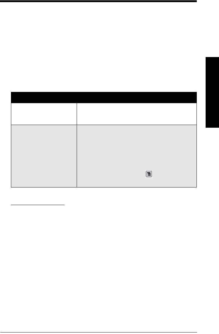
7ML19985JE03 SITRANS LR250 (HART) – INSTRUCTION MANUAL Page 117
mmmmm
B: Troubleshooting
Appendix B: Troubleshooting
Communication Troubleshooting
1) Check the following:
• There is power at the instrument.
• The LCD shows the relevant data.
• The device can be programmed using the handheld programmer.
• If any fault codes are being displayed see
General Fault Codes
on page 119 for a
detailed list.
2) Verify that the wiring connections are correct.
3) See the table below for specific symptoms.
If you continue to experience problems, go to our website at:
www.siemens.com/LR250, and check the FAQs for SITRANS LR250, or contact your
Siemens Milltronics representative.
Symptom Corrective action
The device cannot be pro-
grammed via the handheld pro-
grammer.
• Ensure Write Protect (6.2.1.) on page 114 is set to the unlock
value.
You try to set a SITRANS LR250
parameter via remote communi-
cations but the parameter
remains unchanged.
• Ensure Write Protect (6.2.1.) on page 114 is set to the unlock
value, then try setting the parameter via the handheld pro-
grammer.
• Ensure Access Con trol (6 .1.1.) on page 113 is set to Read/
Write.
• Some parameters can be changed only when the device is
not scanning. Try pressing Mode to put the device into
PROGRAM mode.
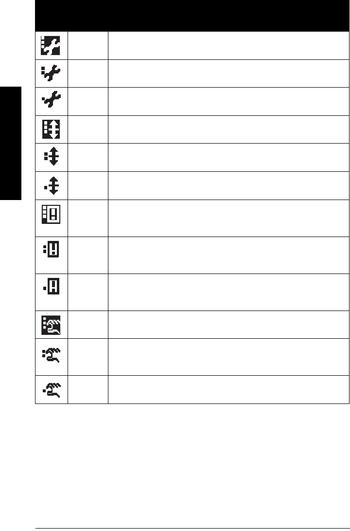
Page 118 SITRANS LR250 (HART) – INSTRUCTION MANUAL 7ML19985JE03
mmmmm
B: Troubleshooting
Device Status Icons
Icon Priority
Level Meaning
1• Maintenance alarm
• Measurement values are not valid
2• Maintenance warning: maintenance demanded immediately
• Measured signal still valid
3• Maintenance required
• Measured signal still valid
1• Process value has reached an alarm limit
2• Process value has reached a warning limit
3• Process value has reached a tolerance limit
1
• Configuration error
• Device will not work because one or more parameters/components is
incorrectly configured
2
• Configuration warning
• Device can work but one or more parameters/components is incorrectly
configured
3
• Configuration changed
• Device parameterization not consistent with parameterization in project.
Look for info text.
1• Manual operation (local override)
• Communication is good; device is in manual mode.
2
• Simulation or substitute value
• Communication is good; device is in simulation mode or works with substi-
tute values.
3• Out of operation
• Communication is good; device is out of action.
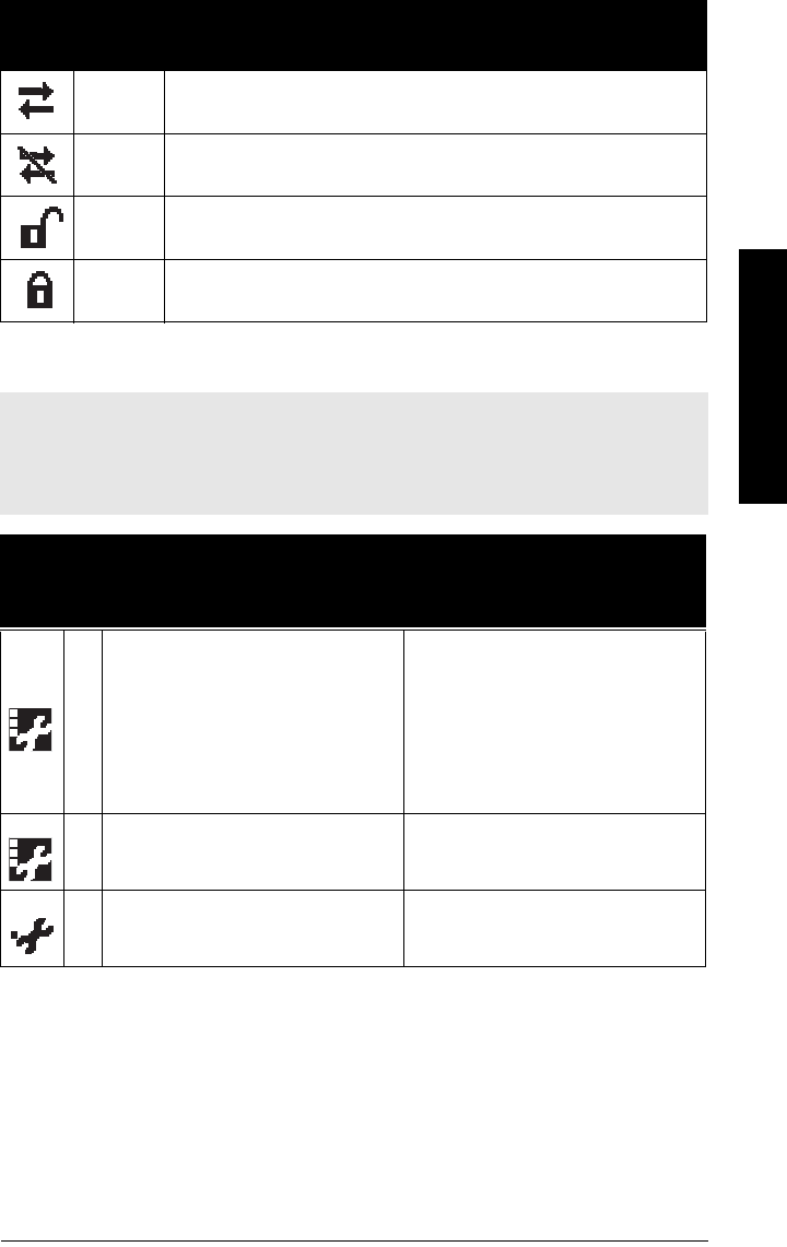
7ML19985JE03 SITRANS LR250 (HART) – INSTRUCTION MANUAL Page 119
mmmmm
B: Troubleshooting
General Fault Codes
•Data exchanged
• No data exchange
• Write access enabled
• Write access disabled
Notes:
• If more than one fault is present, the device status indicator and text for each fault
alternate at 2 second intervals.
• Some faults cause the device to go to Fail-safe mode (Fault 52). These are indicated with
an asterisk (*).
General Fault Codes
Code /
Icon Meaning Corrective Action
S: 0
*
The device was unable to get a measure-
ment within the Fail-safe LOE Timer period.
Possible causes: faulty installation,
antenna material buildup, foaming/other
adverse process conditions, invalid calibra-
tion range.
• Ensure installation details are correct.
• Ensure no antenna material buildup.
Clean if necessary.
• Adjust process conditions to minimize
foam or other adverse conditions.
• Correct range calibration.
• If fault persists, contact your local Sie-
mens representative.
S: 2
*
Unable to collect profile because of a
power condition that is outside the operat-
ing range of the device.
Repair required: contact your local Sie-
mens representative.
S: 3 Device is nearing its lifetime limit according
to the value set in Maintenance Required
Limit.
Replacement is recommended.
Icon Priority
Level Meaning (cont’d)
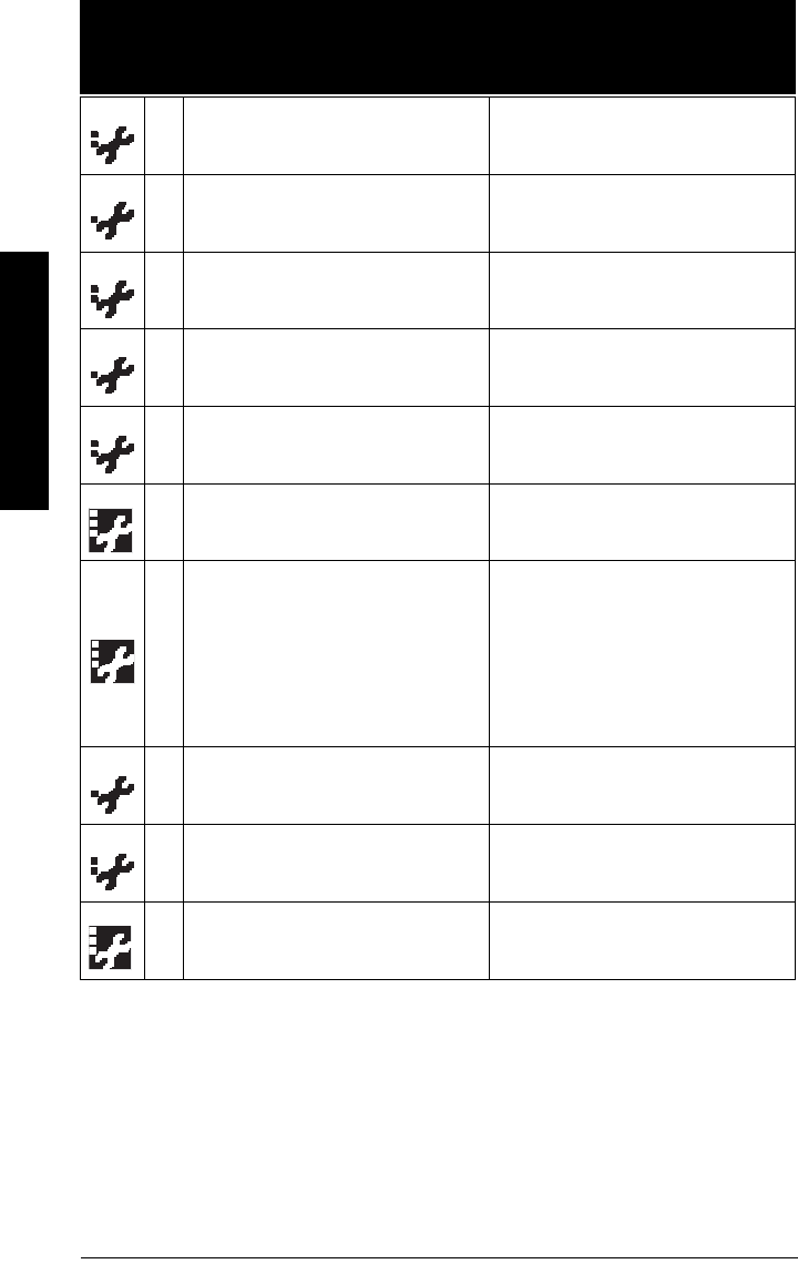
Page 120 SITRANS LR250 (HART) – INSTRUCTION MANUAL 7ML19985JE03
mmmmm
B: Troubleshooting
S: 4 Device is nearing its lifetime limit according
to the value set in Maintenance Demanded
Limit.
Replacement is recommended.
S: 6 Sensor is nearing its lifetime limit according
to the value set in Maintenance Required
Limit.
Replacement is recommended.
S: 7 Sensor is nearing its lifetime limit according
to the value set in Maintenance Demanded
Limit.
Replacement is recommended.
S: 8 Service interval as defined in Maintenance
Required Limit has expired. Perform service.
S: 9 Service interval as defined in Maintenance
Demanded Limit has expired. Perform service.
S: 11
Internal temperature sensor failure. Repair required: contact your local Sie-
mens representative.
S: 12 Internal temperature of device has
exceeded specifications: it is operating out-
side its temperature range.
• Relocate device and/or lower process
temperature enough to cool device.
• Inspect for heat-related damage and
contact your local Siemens representa-
tive if repair is required.
• Fault code will persist until a manual
reset is performed using SIMATIC PEM
or the LCD interface.
S: 17 Calibration interval as defined in Mainte-
nance Required Limit has expired. Perform calibration.
S: 18 Calibration interval as defined in Mainte-
nance Demanded Limit has expired. Perform calibration.
S: 28
*Internal device failure caused by a RAM
memory error.
Repair required: contact your local Sie-
mens representative.
General Fault Codes (cont’d)
Code /
Icon Meaning Corrective Action
7ML19985JE03 SITRANS LR250 (HART) – INSTRUCTION MANUAL Page 121
mmmmm
B: Troubleshooting
S: 29
* EEPROM damaged. Repair required: contact your local Sie-
mens representative.
S: 31
*Flash error. Repair required: contact your local Sie-
mens representative.
S: 33
*Factory calibration for the internal temper-
ature sensor has been lost.
Repair required: contact your local Sie-
mens representative.
S: 34
*Factory calibration for the device has been
lost.
Repair required: contact your local Sie-
mens representative.
S: 35
*Factory calibration for the device has been
lost.
Repair required: contact your local Sie-
mens representative.
S: 36
* Unable to start microwave module. Cycle power. If fault persists, contact your
local Siemens representative.
S: 37
* Measurement hardware problem. Cycle power. If fault persists, contact your
local Siemens representative.
S: 38
* Failure in the device electronics.
Cycle power. If fault persists, contact your
local Siemens representative: repair
required.
S: 43
*Factory calibration for the radar receiver
has been lost.
Repair required: contact your local Sie-
mens representative.
S: 45
*No valid boot program detected: firmware
corrupt.
Repair required: contact your local Sie-
mens representative.
S: 48
*
User configuration is invalid. One or more
of parameters: Low Calibration Point, High
Calibration Point, Volume breakpoints, and/
or Auto False-Echo Suppression, are set to
invalid values.
• Reconfigure the unit.
• Ensure the difference between High Cali-
bration Point and Low Calibration Point is
not less than or equal to zero; do a Mas-
ter Reset.
General Fault Codes (cont’d)
Code /
Icon Meaning Corrective Action
Page 122 SITRANS LR250 (HART) – INSTRUCTION MANUAL 7ML19985JE03
mmmmm
B: Troubleshooting
Operation Troubleshooting
Operating symptoms, probable causes, and resolutions.
S: 49
* EEPROM corrupt. Repair required: contact your local Sie-
mens representative.
S: 50
* EEPROM corrupt. Repair required: contact your local Sie-
mens representative.
S: 51
* EEPROM corrupt. Repair required: contact your local Sie-
mens representative.
S: 52
Fail-safe is activated. Possible causes:
1) hardware failure
2) memory failure
3) Fail-safe LOE timer expired– possible
causes: faulty installation, antenna mate-
rial buildup, foaming/other adverse process
conditions, invalid calibration range.
For 3):
• Correct configuration; ensure installation
is correct;
• no antenna buildup;
• adjust process conditions to minimize
foaming/other adverse conditions;
• correct calibration range.
If fault persists, or for 1) and 2), contact
your local Siemens representative.
S: 53
*
Configuration lost: one or more parameter
settings have been lost. This may occur
after a firmware upgrade causes user
parameters to be reset.
Restore user parameters using SIMATIC
PDM.
Operation Troubleshooting
Symptom Cause Action
Display shows
S: 0 LOE level or target is out of range
• check specifications
• check Low Calibration Pt. (2.3.1.)
• increase Confidence (2.8.6.1.)
Display shows
S: 0 LOE material build-up on antenna • clean the antenna
• re-locate SITRANS LR250
General Fault Codes (cont’d)
Code /
Icon Meaning Corrective Action

7ML19985JE03 SITRANS LR250 (HART) – INSTRUCTION MANUAL Page 123
mmmmm
B: Troubleshooting
Display shows
S: 0 LOE
location or aiming:
• poor installation
• flange not level
• Auto False Echo Suppres-
sion may be incorrectly
applied
• check to ensure nozzle is vertical
• ensure end of antenna protrudes from
end of nozzle
•review
Auto False Echo Suppression
(2.8.7.1.)
on page 130
• ensure Auto False Echo Suppression
Range is set correctly
Display shows
S: 0 LOE
antenna malfunction:
• temperature too high
• physical damage
• excessive foam
• multiple echoes
• check Current Internal Temperature (3.2.1.)
• use foam deflector or stillpipe
• relocate
•use a defoamer
•set Algorithm (2.8.4.1.) to F (First echo)
Reading does not
change, but the level
does
SITRANS LR250 processing
wrong echo, for example, ves-
sel wall, or structural member
• re-locate SITRANS LR250
• check nozzle for internal burrs or welds
• rotate instrument 90°
•use Auto False Echo Suppression (2.8.7.1.)
if necessary: see
Auto False Echo Sup-
pression (2.8.7.1.)
on page 130
Measurement is consis-
tently off by a constant
amount
• setting for Low Calibration
Pt. (2.3.1.) not correct
• setting for Sensor Offset
(2.3.3.) not correct
• check distance from sensor reference
point to Low Calibration Pt. (2.3.1.)
• check Sensor Offset (2.3.3.)
Screen blank
power error
• check nameplate rating against voltage
supply
• check power wiring or source
too much load resistance
• change barrier type, or
• remove something from the loop, or
• increase supply voltage
Reading erratic
echo confidence weak
• refer to Confidence (2.8.6.1.)
•use Auto False Echo Suppression (2.8.7.1.)
and Auto False Echo Suppression Range
(2.8.7.2.)
• use foam deflector or stillpipe
liquid surface vortexed
• decrease Fill Rate (2.4.2.)
• relocate instrument to side pipe
• increase confidence threshold in Echo
Threshold (2.8.4.3.)
material filling • re-locate SITRANS LR250
Operation Troubleshooting (cont’d)
Symptom Cause Action

Page 124 SITRANS LR250 (HART) – INSTRUCTION MANUAL 7ML19985JE03
mmmmm
B: Troubleshooting
Reading response slow Fill Rate (2.4.2.) setting incor-
rect
• increase measurement response if possi-
ble
Reads correctly but occa-
sionally reads high when
vessel is not full
• detecting close range
echo
• build up near top of
vessel or nozzle
• nozzle problem
• clean the antenna
•use Auto False Echo Suppression (2.8.7.1.)
and Auto False Echo Suppression Range
(2.8.7.2.)
Level reading lower than
actual material level
• material is within Near
Range zone
• multiple echoes
processed
• decrease Near Range (2.8.1.) (minimum
value depends on antenna type)
• raise SITRANS LR250
• ensure Algorithm (2.8.4.1.) is set to F (First
echo)
• vessel near empty and
low dK material
• ensure Material (2.2.3.) selection is LIQ-
UID LOW DK
•set Position Detect (2.8.4.2.) to Hybrid
•set CLEF Range (2.8.4.4.) to 0.5 m
Operation Troubleshooting (cont’d)
Symptom Cause Action

7ML19985JE03 SITRANS LR250 (HART) – INSTRUCTION MANUAL Page 125
mmmmm
C: Maintenance
Appendix C: Maintenance
SITRANS LR250 requires no maintenance or cleaning under normal operating conditions.
Under severe operating conditions, the horn antenna may require periodic cleaning. If
cleaning becomes necessary:
• Note the antenna material and the process medium, and select a cleaning solution
that will not react adversely with either.
• Remove the instrument from service and wipe the antenna clean using a cloth and
suitable cleaning solution.
Unit Repair and Excluded Liability
All changes and repairs must be done by qualified personnel, and applicable safety
regulations must be followed. Please note the following:
• The user is responsible for all changes and repairs made to the device.
• All new components must be provided by Siemens Milltronics Process Instruments
Inc.
• Restrict repair to faulty components only.
• Do not re-use faulty components.
Replacing the antenna
• If the antenna requires replacement due to damage, it may be replaced without
need for re-calibration.
• Changing to a different antenna type may be performed by a Siemens authorized
repair center.

Page 126 SITRANS LR250 (HART) – INSTRUCTION MANUAL 7ML19985JE03
mmmmm
D: Technical Reference
Appendix D: Technical Reference
Principles of Operation
SITRANS LR250 is a 2-wire 25 GHz pulse radar level transmitter for continuous monitoring
of liquids and slurries1). Radar level measurement uses the time of flight principle to
determine distance to a material surface. The device transmits a signal and waits for the
return echo. The transit time is directly proportional to the distance from the material.
Pulse radar uses polarized electromagnetic waves. Microwave pulses are emitted from
the antenna at a fixed repetition rate, and reflect off the interface between two materials
with different dielectric constants (the atmosphere and the material being monitored).
Electromagnetic wave propagation is virtually unaffected by temperature or pressure
changes, or by changes in the vapor levels inside a vessel. Electromagnetic waves are
not attenuated by dust.
SITRANS LR250 consists of an enclosed electronic circuit coupled to an antenna and
process connection. The electronic circuit generates a radar signal (25 GHz) that is
directed to the horn.
The signal is emitted from the horn, and the reflected echoes are digitally converted to an
echo profile. The profile is analyzed to determine the distance from the material surface
to the sensor reference point2). This distance is used as a basis for the display of material
level and mA output.
Echo Processing
Process Intelligence
The signal processing technology embedded in Siemens radar level devices is known as
Process Intelligence.
Process intelligence provides high measurement reliability regardless of the dynamically
changing conditions within the vessel being monitored. The embedded Process
Intelligence dynamically adjusts to the constantly changing material surfaces within
these vessels.
Note: Where a number follows the parameter name (for example, Algorithm (2.8.4.1.)
this is the parameter access number via the handheld programmer. See
Parameter
Reference
on page 78 for a complete list of parameters.
1) The microwave output level is significantly less than that emitted from cellular
phones.
2) See
Dimensions
on page 12 and
Flanged Horn with extension
on page 14.
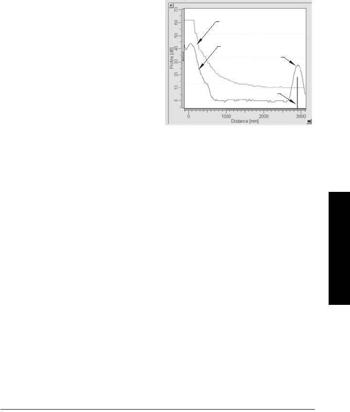
7ML19985JE03 SITRANS LR250 (HART) – INSTRUCTION MANUAL Page 127
mmmmm
D: Technical Reference
Process Intelligence is able to differentiate between the true microwave reflections from
the surface of the material and unwanted reflections being returned from obstructions
such as seam welds or supports within a vessel. The result is repeatable, fast and
reliable measurement. This technology was developed as result of field data gained over
some twenty years from more than 1,000,000 installations in many industries around the
world.
Higher order mathematical techniques and algorithms are used to provide intelligent
processing of microwave reflection profiles. This “knowledge based” technique
produces superior performance and reliability.
Echo Selection
Time Varying Threshold (TVT)
A Time Varying Threshold (TVT) hovers
above the echo profile to screen out
unwanted reflections (false echoes).
In most cases the material echo is the
only one which rises above the default
TVT.
In a vessel with obstructions, a false
echo may occur. See
Auto False Echo
Suppression (2.8.7.1.)
on page 130 for
more details.
The device characterizes all echoes that rise above the TVT as potential good echoes.
Each peak is assigned a rating based on its strength, area, height above the TVT, and
reliability, amongst other characteristics.
Algorithm (2.8.4.1.)
The true echo is selected based on the setting for the Echo selection algorithm. Options
are true First Echo, Largest Echo, or best of First and Largest.
Position Detect (2.8.4.2.)
The echo position detection algorithm determines which point on the echo will be used to
calculate the precise time of flight, and calculates the range using the calibrated
propagation velocity (see Propagation Factor (2.8.3.) for values). There are three options:
•Center
•CLEF (Constrained Leading Edge Fit)
• Hybrid
default TVT
material
level
echo marker
echo profile
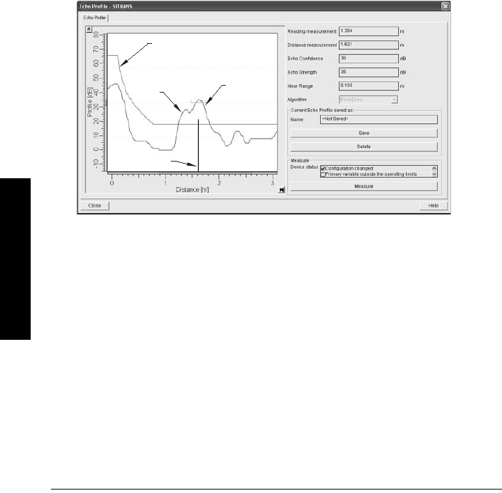
Page 128 SITRANS LR250 (HART) – INSTRUCTION MANUAL 7ML19985JE03
mmmmm
D: Technical Reference
Center
Uses center of the echo.
Hybrid
Uses the Center algorithm for the top part of the vessel, and the CLEF algorithm for the
part nearest the vessel bottom, according to the setting for CLEF range.
CLEF (Constrained Leading Edge Fit)
• Uses the leading edge of the echo.
• Is used mainly to process the echo from materials with a low dK value.
In an almost empty flat-bottomed vessel, a low dK material may reflect an echo weaker
than the echo from the vessel bottom. The echo profile shows these echoes merging. The
device may then report a material level equal to or lower than empty
The CLEF algorithm enables the device to report the level correctly.
Example: CLEF off: Position set to Hybrid
default TVT
vessel
bottom
echo
selected
material
echo
echo marker
Vessel height: 1.5 m; CLEF range set to 0 (Center algorithm gives the same result.)
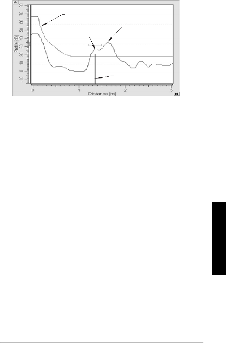
7ML19985JE03 SITRANS LR250 (HART) – INSTRUCTION MANUAL Page 129
mmmmm
D: Technical Reference
Example: CLEF enabled
CLEF Range (2.8.4.4.)
Determines the level below which the CLEF algorithm will be used. Above this level the
Center algorithm is used.
Echo Threshold (2.8.4.3.)
Confidence (2.8.6.1.) describes the quality of an echo. Higher values represent higher
quality. Echo Threshold defines the minimum confidence value required for an echo to be
accepted as valid and evaluated.
Echo Lock (2.8.5.1.)
If the echo selected by Algorithm is within the Echo Lock window, the window is centered
about the echo, which is used to derive the measurement. In radar applications, two
measurement verification options are used:
Lock Off
SITRANS LR250 responds immediately to a new selected echo (within the restrictions set
by the Maximum Fill / Empty Rate), but measurement reliability is affected.
Material Agitator
A new measurement outside the Echo Lock Window must meet the sampling criteria
before the window will move to include it.
The other available options, Maximum Verification and Tot al Lock are not recommended
for radar.
default TVT
vessel
bottom
echo
material
echo
selected
echo marker
Vessel height: 1.5 m; CLEF range set to 0.5 m
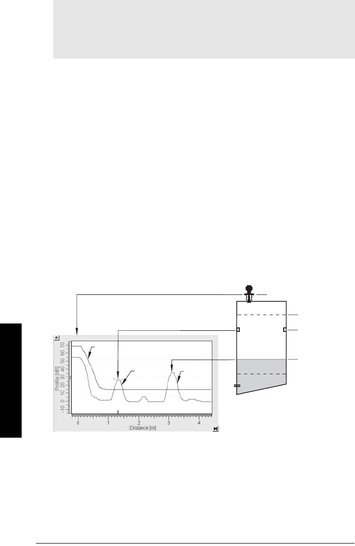
Page 130 SITRANS LR250 (HART) – INSTRUCTION MANUAL 7ML19985JE03
mmmmm
D: Technical Reference
Auto False Echo Suppression (2.8.7.1.)
Auto False Echo Suppression is designed to learn a specific environment (for example, a
particular vessel with known obstructions), and in conjunction with Auto False Echo
Suppression Range to remove false echoes appearing in front of the material echo.
The material level should be below all known obstructions at the moment when Auto
False Echo Suppression learns the echo profile. Ideally the vessel should be empty or
almost empty, and if an agitator is present, it should be running.
The device learns the echo profile over the whole measurement range and the TVT is
shaped around all echoes present at that moment.
Auto False Echo Suppression Range (2.8.7.2.)
Auto False Echo Suppression Range specifies the range within which the learned TVT is
applied. Default TVT is applied over the remainder of the range.
The learned TVT screens out the false echoes caused by obstructions. The default TVT
allows the material echo to rise above it.
Auto False Echo Suppression Range must be set to a distance shorter than the distance
to the material level when the environment was learned, to avoid the material echo being
screened out.
Notes:
• For detailed instructions on using this feature via PDM see
Auto False Echo
Suppression
on page 52.
• For detailed instructions on using this feature via the handheld programmer see
Auto False Echo Suppression (2.8.7.1.) on page 94.
High Cal. Pt.
= 0
obstruction
at 1.3 m
material
level at
3.2 m
false
echo
material
echo
default
TVT
sensor reference point
Example before Auto False Echo Suppression
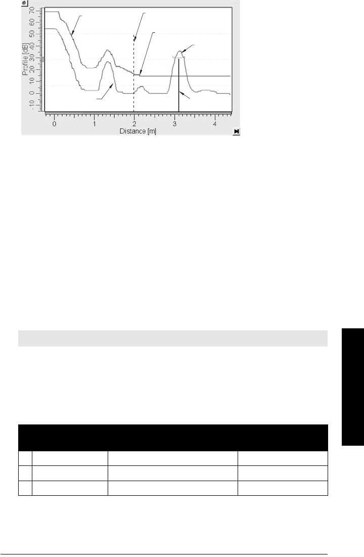
7ML19985JE03 SITRANS LR250 (HART) – INSTRUCTION MANUAL Page 131
mmmmm
D: Technical Reference
Measurement Range
Near Range (2.8.1.)
Near Range programs SITRANS LR250 to ignore the zone in front of the antenna. The
default blanking distance is 50 mm (1.97") from end of horn antenna.
Near Range allows you to increase the blanking value from its factory default. But Auto
False Echo Suppression (2.8.7.1.) is generally recommended in preference to extending the
blanking distance from factory values.
Far Range (2.8.2.)
Far Range can be used in applications where the base of the vessel is conical or
parabolic. A reliable echo may be available below the vessel empty distance, due to an
indirect reflection path.
Increasing Far Range to 30% or 40% can provide stable empty vessel readings.
Measurement Response
Response Rate (2.4.1.) limits the maximum rate at which the display and output respond to
changes in the measurement. There are three preset options: slow, medium, and fast.
Once the real process fill/empty rate (m/s by default) is established, a response rate can
be selected that is slightly higher than the application rate. Response Rate automatically
adjusts the filters that affect the output response rate.
Note: Units are defined in Units (2.2.1.) and are in meters by default.
Response Rate
(2.4.1.)
Fill Rate (2.4.2.)/
Empty rate (2.4.3.)
Damping Filter
(2.2.4.)
*Slow 0.1 m/min (0.32 ft/min) 10 s
Medium 1.0 m/min (3.28 ft/min) 10 s
Fast 10.0 m/min (32.8 ft/min) 0 s
Example after Auto False Echo Suppression
learned
TVT
material
echo
false echo echo
marker
Auto False Echo
Suppression
Range set to 2 m
Auto False Echo
Suppression Range
default
TVT

Page 132 SITRANS LR250 (HART) – INSTRUCTION MANUAL 7ML19985JE03
mmmmm
D: Technical Reference
Damping
Damping Filter (2.2.4.) smooths out the response to a sudden change in level. This is an
exponential filter and the engineering unit is always in seconds.
In 5 time constants the output rises exponentially: from 63.2% of the change in the first
time constant, to almost 100% of the change by the end of the 5th time constant.
Analog Output
The mA Output (current output) is proportional to material level in the range 4 to 20 mA.
0% and 100% are percentages of the full-scale reading (m, cm, mm, ft, in). Typically mA
output is set so that 4 mA equals 0% and 20 mA equals 100%.
When SITRANS LR250 is put into PROGRAM mode (for example, by navigating through
the menu) it stops updating the output of the device (local user interface and mA Output).
It stores the most recent measurement, and holds the associated readings and mA signal
output. The device reverts to the parameter last addressed during the previous program
session.
When the device is returned to Measurement mode, the transceiver resumes operation.
The reading and mA output default to the last measurement taken. The reading and
associated outputs migrate to the current process level at a rate controlled by Response
Rate (2.4.1.).
If the device is left in PROGRAM
mode for 10 minutes without input, it automatically
reverts to Measurement mode.
0
0.5
1
1.5
2
2.5
3
3.5
4
4.5
1234567
Series1 Series2
Level (m)
Time (s)
smoothed output
input (level)
Damping example
time constant = 2 seconds
input (level) change = 2 m
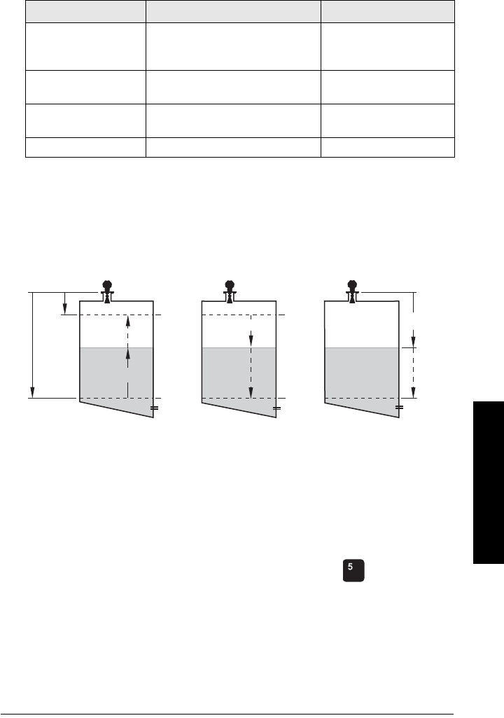
7ML19985JE03 SITRANS LR250 (HART) – INSTRUCTION MANUAL Page 133
mmmmm
D: Technical Reference
Sensor Mode
This parameter controls the input. Depending on the reference point used, the
measurement reports either Level, Space, or Distance. By default Sensor Mode is set to
Level.
You also have the option to put the device out of service, in which case the device
defaults to Fail-safe mode, and the reported level depends on the device type. A standard
device reports the last valid reading, and a NAMUR NE 43-compliant device reports the
user-defined value for Material Level (3.58 mA by default).
Current Output Function
Current Output Function (2.6.1.) controls the mA output and applies any relevant scaling.
By default it is set to Level. Other options are Space, Distance., and Volume. (The device
can carry out a volume calculation only after a vessel shape has been specified.)
When a volume application type is chosen, Sensor Mode remains as Level and the mA
Output is automatically converted to Volume.
To view the mA reading in the secondary region of the LCD, press on the handheld
programmer.
Operation Description Reference point
NO
SERVICE
Measurement and associated loop
current not being updated. Device
defaults to Fail-safe modea).
a) See
Fail-safe Mode
on page 134.
LEVEL Distance to material surface Low Calibration Point (pro-
cess empty level)
SPACE Distance to material surface High Calibration Point (pro-
cess full level)
DISTANCE Distance to material surface Sensor Reference Point
Level Space Distance
Distance
Space
Level
20 mA
100%
4 mA
0%
High
Cal.
Pt.
4 mA
0%
20 mA
100%
4 mA
0%
20 mA
100%
Sensor
reference
point
Low
Cal.
Pt
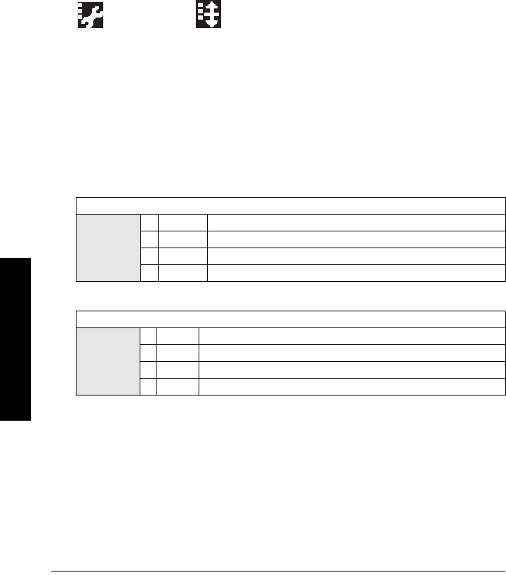
Page 134 SITRANS LR250 (HART) – INSTRUCTION MANUAL 7ML19985JE03
mmmmm
D: Technical Reference
Loss of Echo (LOE)
A loss of echo (LOE) occurs when the calculated measurement is judged to be unreliable
because the echo confidence value has dropped below the echo confidence threshold.
Confidence (2.8.6.1.) describes the quality of an echo. Higher values represent higher
quality.
Echo Threshold (2.8.4.3.) defines the minimum confidence value required for an echo to
be accepted as valid and evaluated.
If the LOE condition persists beyond the time limit set in Timer (2.5.2.) the LCD displays the
Service Required icon, and the text region displays the fault code S: 0 and the text LOE.
If two faults are present at the same time, the fault code, error text, and error icon for
each fault are displayed alternately. For example, Loss of Echo and Fail-safe.
S: 0 LOE S: 52 Fail-safe
Fail-safe Mode
The purpose of the Fail-safe setting is to put the process into a safe mode of operation in
the event of a fault or failure. The value to be reported in the event of a fault is selected so
that a loss of power or loss of signal triggers the same response as an unsafe level.
Timer (2.5.2.) determines the length of time a Loss of Echo (LOE) condition will persist
before a Fail-safe state is activated. The default setting is 100 seconds.
Material Level (2.5.1.) determines the material level to be reported when Timer (2.5.2.)
expires, depending on the device type (standard or NAMUR NE 43-compliant.)
Upon receiving a reliable echo, the loss of echo condition is aborted, the Service
Required icon and error message are cleared, and the reading and mA output return to
the current material level.
STANDARD DEVICE
Options
HI 20.5 mA (max. mA Limit)
LO 3.8 mA (min. mA Limit)
*HOLDLast valid reading
VALUE User-selected value defined in Level (2.5.3.)
NAMUR NE 43-COMPLIANT DEVICE
Options
HI 20.5 mA (max. mA Limit)
LO 3.8 mA (min. mA Limit)
HOLD Last valid reading
* VALUE User-selected value Level (2.5.3.), default 3.58 mA
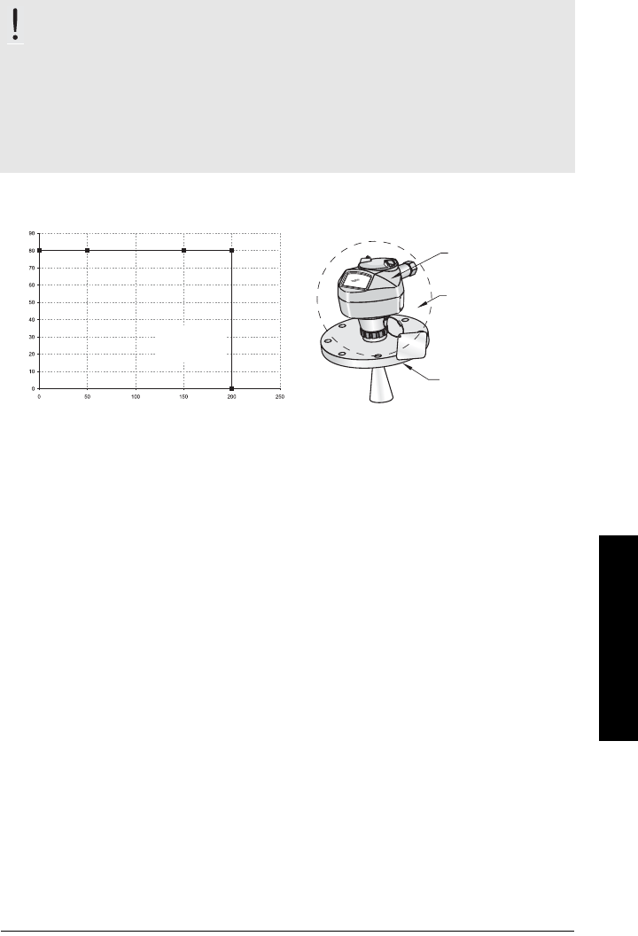
7ML19985JE03 SITRANS LR250 (HART) – INSTRUCTION MANUAL Page 135
mmmmm
D: Technical Reference
Maximum Process Temperature Chart
Flange Adapter versions of SITRANS LR250
.
Where the chart does not apply, please use your own judgement regarding the use of
SITRANS LR250.
See Current Internal Temperature (3.2.1.) on page 98 to monitor the Internal Temperature.
If the internal temperature exceeds the maximum allowable limit, a sun shield or a longer
nozzle may be required.
WARNING: Internal temperature must not exceed 80 °C (176 °F).
Notes:
• The chart below is for guidance only.
• The chart does not represent every possible process connection arrangement. For
example, it will NOT apply if you are mounting SITRANS LR250 directly on a metallic
vessel surface.
• The chart does not take into consideration heating from direct sunshine exposure.
process
temperature
Ambient Temperature (oC)
Process Temperature (oC)
Maximum Process Temperatures versus allowable ambient
ambient
temperature
internal enclosure
temperature
process
temperature

Page 136 SITRANS LR250 (HART) – INSTRUCTION MANUAL 7ML19985JE03
mmmmm
D: Technical Reference
Process Pressure/Temperature derating curves
1)
WARNINGS:
• Never attempt to loosen, remove or disassemble process connection
or instrument housing while vessel contents are under pressure.
• This product is designated as a Pressure Accessory per Directive 97/ 23 / EC
and is not intended for use as a safety device.
• Materials of construction are chosen based on their chemical
compatibility (or inertness) for general purposes. For exposure to
specific environments, check with chemical compatibility charts
before installing.
• The user is responsible for the selection of bolting and gasket
materials which will fall within the limits of the flange and its intended
use and which are suitable for the service conditions.
• Improper installation may result in loss of process pressure and/or
release of process fluids and/or gases.
Notes:
• The Process Device Tag shall remain with the process pressure boundary
assembly1). In the event the instrument package is replaced, the Process Device Tag
shall be transferred to the replacement unit.
• SITRANS LR250 units are hydrostatically tested, meeting or exceeding the
requirements of the ASME Boiler and Pressure Vessel Code and the European
Pressure Equipment Directive.
• The serial numbers stamped in each process connection body, (flange, threaded, or
sanitary), provide a unique identification number indicating date of manufacture.
Example: MMDDYY – XXX (where MM = month, DD = day, YY = year, and
XXX= sequential unit produced)
Further markings (space permitting) indicate flange configuration, size, pressure
class, material, and material heat code.
1) The process pressure boundary assembly comprises the components that act as a
barrier against pressure loss from the process vessel: that is, the combination of pro-
cess connection body and emitter, but normally excluding the electrical enclosure.
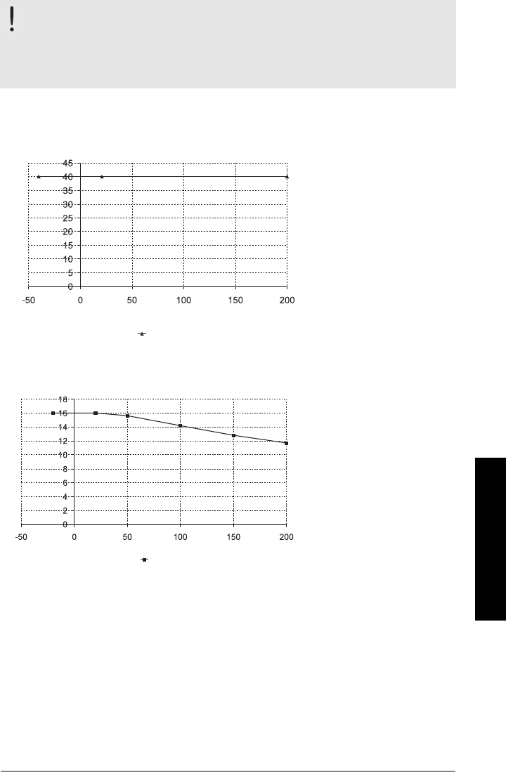
7ML19985JE03 SITRANS LR250 (HART) – INSTRUCTION MANUAL Page 137
mmmmm
D: Technical Reference
Horn Antenna or Wave Guide
1.5" and 2" Threaded Versions
50A, 80A and 100A Flanged Versions: JIS 10 k
WARNING: Never attempt to loosen, remove or disassemble process
connection or instrument housing while vessel contents are under
pressure.
Note: Customer to provide adequate bolting and gasketing to retain vessel pressure and
provide sufficient sealing.
process temperature (°C)
pressure (bar, gauge)
1.5”and 2" NPT/BSP G
Process Connection Series:
• 51209 or 51251 series
fittings.
• Ensure your instrument
has the process
identification Tag showing
one of this series, and
25517 or 25555 stamped on
threaded fitting.
Process Connection Series:
• 51242 or 51252 series
flange.
• Ensure your instrument
has the process
identification Tag showing
one of this series, and
25546, 25547, 25580 or
25581 stamped on flange.
process temperature (°C)
JIS 10 k
pressure (bar, gauge)
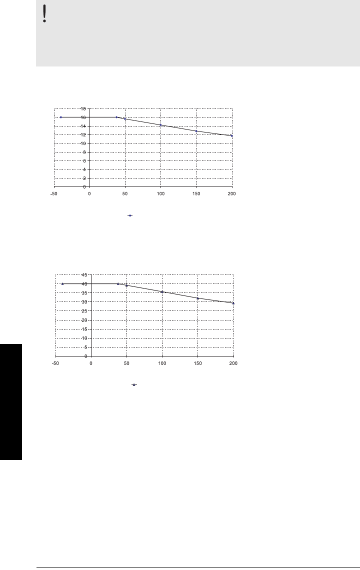
Page 138 SITRANS LR250 (HART) – INSTRUCTION MANUAL 7ML19985JE03
mmmmm
D: Technical Reference
DN50, DN80, DN100, and DN150 Flanged Versions: PN16
DN50, DN80, DN100, and DN150 Flanged Versions: PN40
WARNING: Never attempt to loosen, remove or disassemble process
connection or instrument housing while vessel contents are under
pressure.
Note: Customer to provide adequate bolting and gasketing to retain vessel pressure and
provide sufficient sealing.
Process Connection Series:
• 51242 or 51252 series flange.
• Ensure your instrument has
the Process Identification
Tag showing one of this
series, and 25547, 25581,
25656, or 25657 stamped on
flange.
PN16
pressure (bar, gauge)
process temperature (°C)
Process Connection Series:
• 51242 or 51252 series
flange.
• Ensure your instrument
has the Process
Identification Tag showing
one of this series, and
25547, 25581, 25656, or
25657 stamped on flange.
process temperature (°C)
PN40
pressure (bar, gauge)
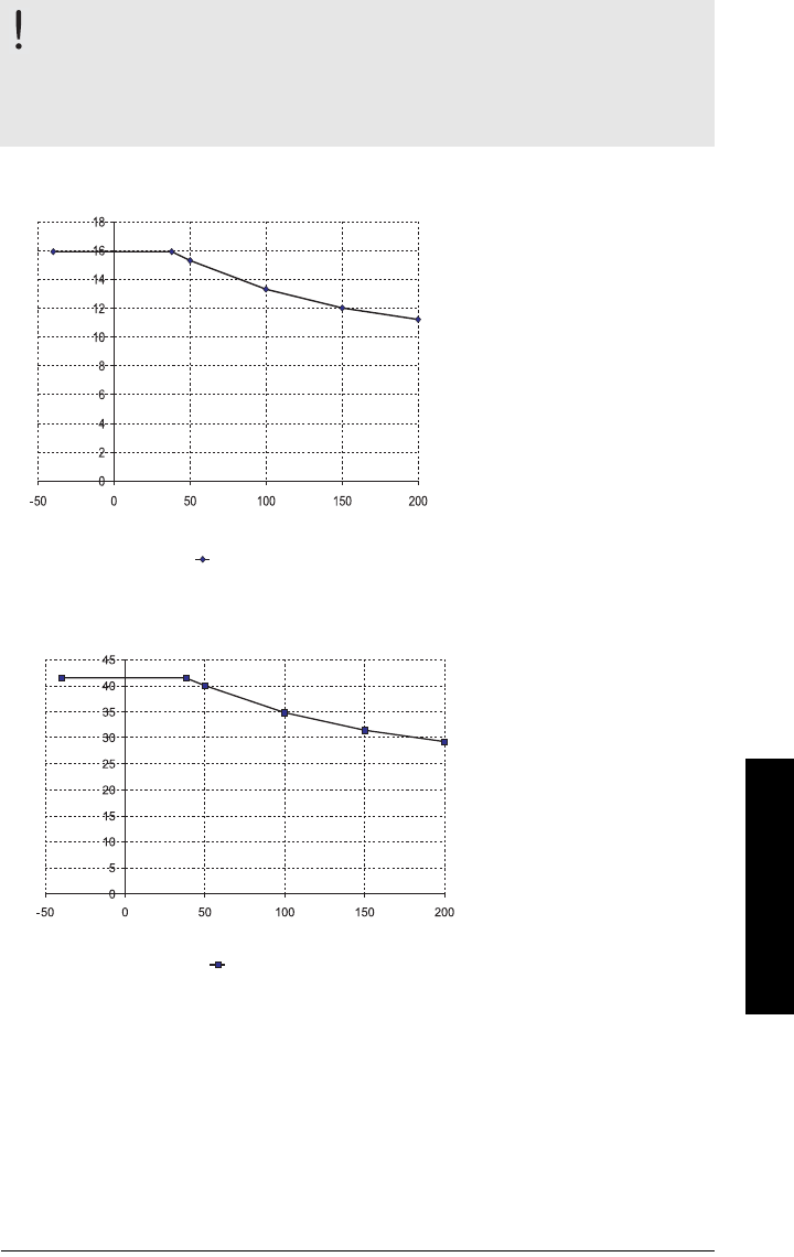
7ML19985JE03 SITRANS LR250 (HART) – INSTRUCTION MANUAL Page 139
mmmmm
D: Technical Reference
2", 3", and 4" Flanged Versions: 150 lb
2", 3", and 4" Flanged Versions: 300 lb
WARNING: Never attempt to loosen, remove or disassemble process
connection or instrument housing while vessel contents are under
pressure.
Note: Customer to provide adequate bolting and gasketing to retain vessel pressure and
provide sufficient sealing.
Process Connection Series:
• 51242 or 51252 series
flange.
• Ensure your instrument has
the process identification
Tag showing one of this
series, and 25546 or 25580
stamped on flange.
process temperature (°C)
150 lb
pressure (bar, gauge)
Process Connection Series:
• 51242 or 51252 series
flange.
• Ensure your instrument
has the process
identification Tag showing
one of this series, and
25546 or 25580 stamped
on flange.
process temperature (°C)
pressure (bar, gauge)
300 lb
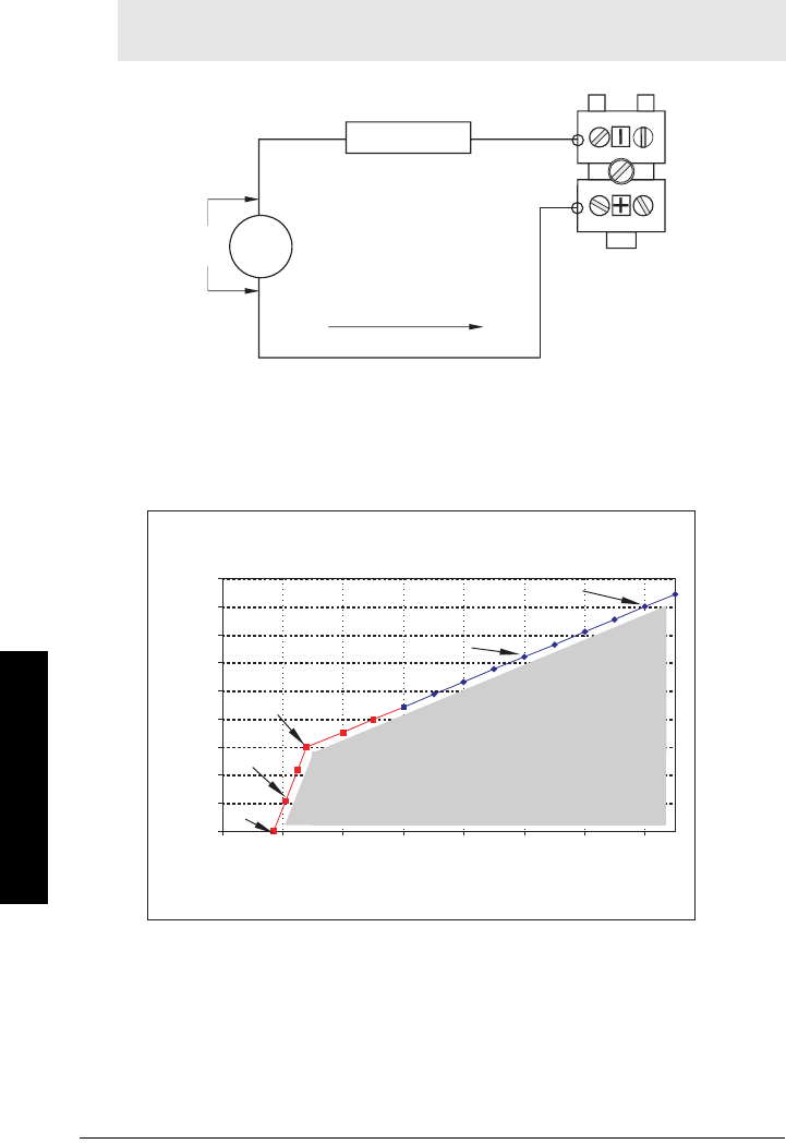
Page 140 SITRANS LR250 (HART) – INSTRUCTION MANUAL 7ML19985JE03
mmmmm
D: Technical Reference
Loop power
Typical Connection Drawing
Allowable operating area of SITRANS LR250
Curve 1 (General Purpose, Intrinsically Safe, Non-incendive)
Loop Voltage versus Loop Resistance
Note: Loop voltage is the voltage at the terminals of the power supply (not the voltage
at the terminals of the device).
+
-
LR250
loop resistance
RL
loop current IL
loop voltage
VL
power
supply
Power Supply Requirements
0
100
200
300
400
500
600
700
800
900
15 17 19 21 23 25 27 29
Loop Voltage - V
L
(Source Voltage)
Loop Resistance - R
L
(30.0V, 845 ohms)
RL = 44.6 * VL - 493.4
(17.8V, 300 ohms)
(16.7V, 0 ohms)
RL = 272.7 * VL - 4554.1
Loop Voltage – VL
Loop Resistance – RL
ALLOWABLE
OPERATING AREA
Power Supply Requirements
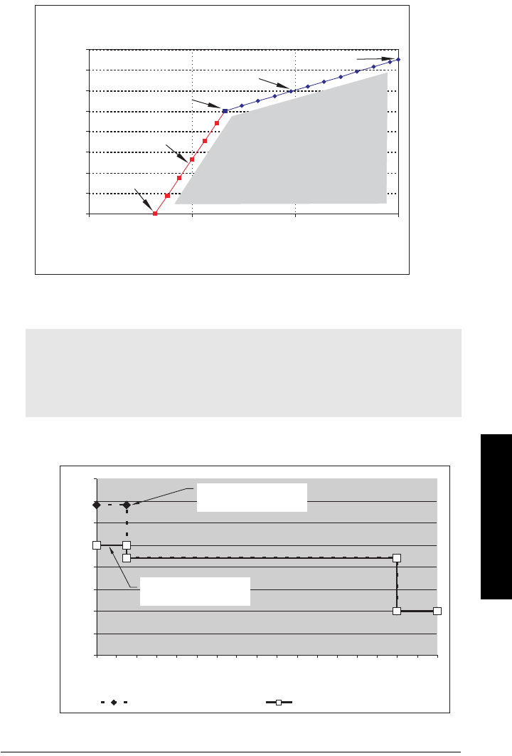
7ML19985JE03 SITRANS LR250 (HART) – INSTRUCTION MANUAL Page 141
mmmmm
D: Technical Reference
Curve 2 (Flameproof, Increased Safety, Explosion-proof)
Loop Voltage versus Loop Resistance
Startup Behavior
Notes:
• SITRANS LR250 is designed to start reliably with a power supply capable of
delivering at least 25 mA.
• When connected to a power supply with a current limit of < 25 mA, the LR250 may
not start reliably.
Power Supply Requirements
0
50
100
150
200
250
300
350
400
15 20 25 30
Loop Voltage - VL
(Source Voltage)
Loop Resistance - R L
(30.0V, 375 ohms)
RL = 14.88 * VL - 71.43
(21.6V, 250 ohms)
(18.2V, 0 ohms)
RL = 73.53 * VL - 1338.24
Power Supply Requirements
Loop Voltage – VL
Loop Resistance – RL
ALLOWABLE
OPERATING AREA
0
5
10
15
20
25
30
35
40
0 2 4 6 8 10 12 14 16 18 20 22 24 26 28 30 32 34
Time (seconds)
Current (mA)
No Current Limit Current Limited Power Supply
Typical Startup Current
Time (seconds)
Current (mA)
Loop Power Supply
without Current Limit
Loop Power Supply with
25 mA Current Limit
Current-limited powerNo current limit
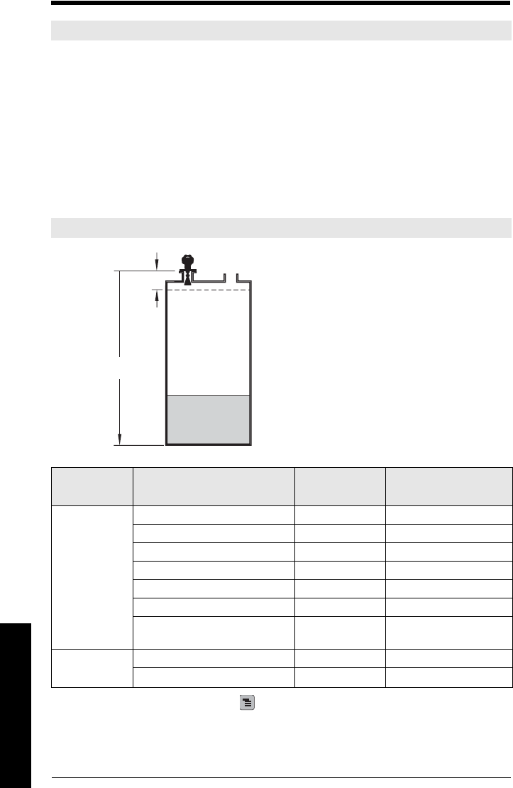
Page 142 SITRANS LR250 (HART) – INSTRUCTION MANUAL 7ML19985JE03
mmmmm
E: Application Examples
Appendix E: Application Examples
You can use these examples as setup references. Enter the values in the parameter tables to
select the corresponding functions.
Configure the basic settings using the Quick Start wizard parameters. (These parameters are
inter-related, and changes take effect only after you select YES to apply changes in the last
step.)
In each example, after performing a Quick Start, navigate to the other required parameters
either via the handheld programmer, or using a Device Management tool (SIMATIC PDM or
AMS Device Manager) and enter the appropriate values.
Liquid resin in storage vessel, level measurement
Return to Measurement: press Mode to start normal operation.
Note: In the applications illustrated below, values are for example purposes only.
Note: Minimum distance from flange face to target is limited by Near Range (2.8.1.).
Parameter
type Parameter No. /Name Options/
Values Function
Quick Start
Wizard
parameters
Material (1.2.) LIQUID
Response Rate (1.3.) MED Medium =1 m/minute
Units (1.4.) M meters
Operation Mode (1.5.) LEVEL Level
Low Calibration Point (1.6.) 5 5 m (16.5 ft)
High Calibration Point (1.7.) 0.5 0.5 m (1.64 ft)
Apply? (Apply changes) (1.8.) YES Transfers Quick Start
settings to device.
Independent
parameters
Timer (2.5.2.) 2 2 minutes
Material Level (2.5.1.) HI Fail-safe level set to High
To obtain level measurement/4 to 20 mA output
proportional to resin levels:
Low Calibration Pt. = 5 m (16.5 ft) from sensor
reference point
High Calibration Pt.= 0.5 m (1.64 ft) from sensor
reference point
Max.fill/empty rate = 0.2 m/min (0.65 ft/min)
In the event of a loss of echo:
SITRANS LR250 is to go into Fail-safe High after 2
minutes.
0.5 m
Low Cal
Point
5 m
100% Level
0% Level
High
Cal
Point
sensor
reference
point
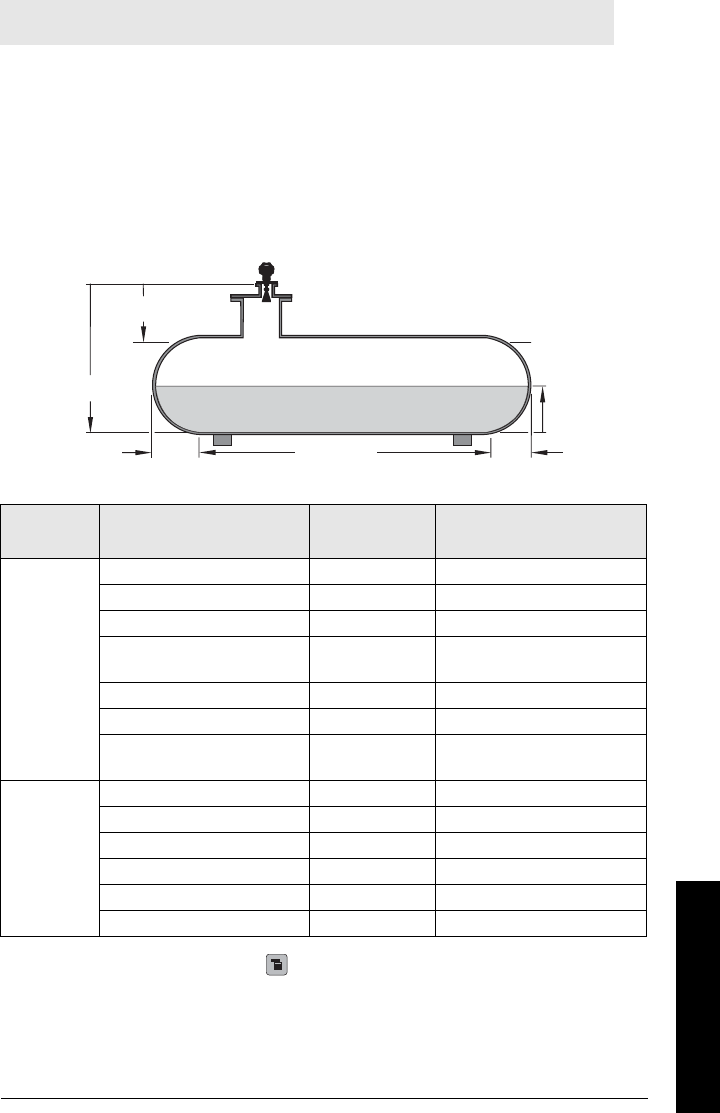
7ML19985JE03 SITRANS LR250 (HART) – INSTRUCTION MANUAL Page 143
mmmmm
E: Application Examples
Horizontal vessel with volume measurement
To obtain level measurement/4 to 20 mA output proportional to vessel volume in a chemical
vessel:
Low Calibration Point = 3.5 m (11.48 ft) from sensor reference point
High Calibration Point = 0.5 m (1.64 ft) from sensor reference point
Max. fill/empty rate = 0.2 m/min (0.65 ft/min)
Select vessel shape, Parabolic Ends, and enter values for A and L, to obtain a volume reading
instead of level.
In the event of a loss of echo: SITRANS LR250 is to go into Fail-safe High after 2 minutes.
Return to Measurement: press Mode to start normal operation.
Note: The minimum distance from the flange face to the target is limited by Near Range
(2.8.1.).
Parameter
type Parameter No./Name Options/
Values Function
Quick
Start
Wizard
parame-
ters
Material (1.2.) LIQUID
Response Rate (1.3.) MED Medium =1 m/minute
Units (1.4.) M meters
Operation Mode (1.5.) LEVEL Level is reported as Volume
when a vessel shape is selected.
Low Calibration Point (1.6.) 3.5 3.5 m (11.48 ft)
High Calibration Point (1.7.) 0.5 0.5 m (1.64 ft)
Apply? (Apply changes) (1.8.) YES Transfers Quick Start settings to
device.
Indepen-
dent
parame-
ters
Vesse l S hape (2.7.1.1.) PAR ABOL IC EN DS Defines vessel shape.
Maximum Volume (2.7.1.2.) 8000 8000 liters
Dimension A (2.7.1.3.) 0.8 0.8 m (2.62 ft)
Dimension L (2.7.1.4.) 6 6 m (19.68 ft)
Timer (2.5.2.) 2 2 minutes
Material Level (2.5.1.) HI Fail-safe level set to High
volume
reading
3.5 m
A
= 0.8 m
L
= 6 m
Low Cal
Point
100% = 8000 l
sensor
reference
point
A
= 0.8 m
High
Cal
Point
0.5 m
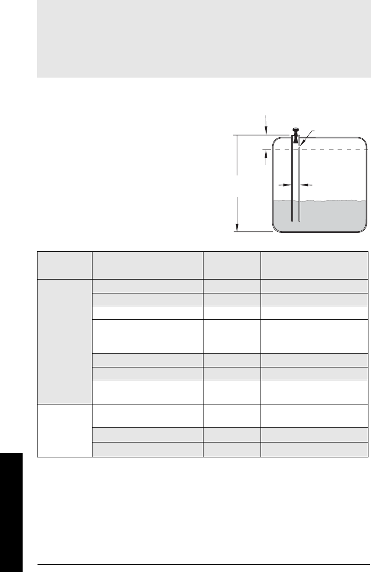
Page 144 SITRANS LR250 (HART) – INSTRUCTION MANUAL 7ML19985JE03
mmmmm
E: Application Examples
Application with Stillpipe
This application is to obtain a level measurement and corresponding 4 to 20 mA output
proportional to the oil level in a fuel storage vessel.
Notes:
•Near Range (2.8.1.) (Blanking) will be set at the factory. Check the Process Device Tag for
specific values.
• Suitable pipe diameters are 40 mm (1.5”) to 100 mm (4”).
• The pipe diameter must be matched with the horn size. Use the largest horn size that will
fit the stillpipe/bypass pipe (see
Dimensions
on page 12).
• See
Mounting on a Stillpipe or Bypass Pipe
on page 22 for installation guidelines.
Parameter
type Parameter No./Name Options/
Values Function
Quick Start
Wizard
Material (1.2.) LIQUID LOW DK
Response Rate (1.3.) MED Medium =1 m/minute
Units (1.4.) M meters
Operation Mode (1.5.) LEVEL
Level is reported as Volume
when a vessel shape is
selected.
Low Calibration Point (1.6.) 55 m (16.5 ft)
High Calibration Point (1.7.) 0.5 0.5 m (1.64 ft)
Apply? (Apply changes) (1.8.) YES Transfers Quick Start settings to
device.
Indepen-
dent
parameters
Propagation Factor (2.8.3.)a)
a) The recommended values for the propagation factor and for CLEF range are dependent
on the stillpipe diameter. See
Propagation Factor/Stillpipe Diameter
on page 145 for val-
ues.
0.990 P.F. for a 50 mm (1.96") I.D.
stillpipe
Position Detect (2.8.4.2.) HYBRID
CLEF Range (2.8.4.4.)a4.3 4.3 m (14.10 ft)
• Low Calibration Pt. is 5 m (16.5 ft) from
the sensor reference point.
• High Calibration Pt. is 0.5 m (1.65 ft)
from the sensor reference point.
• The stillpipe inside diameter is
50 mm (1.96").
• The maximum rate of filling or
emptying is about 0.1 m (4")/min.
5 m
0.5 m
sensor
reference
point
Low Cal.
Pt.
High
Cal.
Pt.
50 mm I.D.
vent hole

7ML19985JE03 SITRANS LR250 (HART) – INSTRUCTION MANUAL Page 145
mmmmm
E: Application Examples
Propagation Factor/Stillpipe Diameter
Nominal Pipe Size a)
a) Since pipe dimensions may vary slightly, the propagation factor may also vary.
40 mm (1.5”) 50 mm (2”) 80 mm (3”) 100 mm (4”)
Propagation Factor 0.9828 0.990 0.991 0.9965
CLEF Range (2.8.4.4.)
settings
Low Cal Pt. –
700 mm
Low Cal Pt. –
700 mm
Low Cal Pt. –
1000 mm
Low Cal Pt. –
1000 mm

Page 146 SITRANS LR250 (HART) – INSTRUCTION MANUAL 7ML19985JE03
mmmmm
F: HART Communications
Appendix F: HART Communications
Highway Addressable Remote Transducer, HART, is an industrial protocol that is
superimposed on the 4-20 mA signal. It is an open standard, and full details about HART
can be obtained from the HART Communication Foundation at www.hartcomm.org
SITRANS LR250 can be configured over the HART network using either the HART
Communicator 375 by Fisher-Rosemount, or a software package. The recommended
software package is the SIMATIC Process Device Manager (PDM) by Siemens.
SIMATIC PDM
This software package is designed to permit easy configuration, monitoring, and
troubleshooting of HART devices. The HART EDD for SITRANS LR250 was written with
SIMATIC PDM in mind and has been extensively tested with this software.
For more information, see
Operating via SIMATIC PDM
on page 40.
HART Electronic Device Description (EDD)
In order to configure a HART device, the configuration software requires the HART
Electronic Device Description for the instrument in question.
You can download the HART EDD for SITRANS LR250 from the product page of our
website. Go to: www.siemens.com/LR250 and click on Downloads.
Older versions of the library will have to be updated in order to use all the features of
SITRANS LR250.

7ML19985JE03 SITRANS LR250 (HART) – INSTRUCTION MANUAL Page 147
mmmmm
F: HART Communications
HART Communicator 375 Menu Structure
LEVEL METER
1. IDENTIFICATION
1. TAG
2. DESCRIPTION
3. MESSAGE
4. INSTALLATION DATE
5. DEVICE ORDER NUMBER
2. SETUP
1. DEVICE
1. FIRMWARE REVISION
2. LOADER REVISION
3. HARDWARE REVISION
2. INPUT
1. SENSOR CALIBRATION
1. MATERIAL
2. SENSOR UNITS
3. OPERATION
4. LOW CALIBRATION PT.
5. HIGH CALIBRATION PT.
6. NEAR RANGE
7. FAR RANGE
8. PROPAG. FACTOR
9. SENSOR OFFSET
2. VOLUME CONVERSION
1. VESSEL SHAPE
2. MAXIMUM VOLUME
3. DIMENSION A
4. DIMENSION L
3. VOLUME BREAKPOINT
1. TABLE 1 – 8 (Lev./Vol. Breakpoints 1-8)
2. TABLE 9 – 16 (Lev./Vol. Breakpoints 9-16)
3. TABLE 17 – 24 (Lev./Vol. Breakpoints 17-24)
4. TABLE 25 – 32 (Lev./Vol. Breakpoints 25-32)
4. ECHO PROCESSING
1. ECHO SELECT
1. ALGORITHM
2. POSITION DETECT
3. ECHO THRESHOLD
2. SAMPLING
1. ECHO LOCK
2. SAMPLING UP
3. SAMPLING DOWN
4. WINDOW
3. FILTERING
1. DAMPING FILTER
4. TANK BOTTOM ALGORITHM
1. CLEF RANGE
Note: HART Communicator 375 is supported by SITRANS LR250 HART.

Page 148 SITRANS LR250 (HART) – INSTRUCTION MANUAL 7ML19985JE03
mmmmm
F: HART Communications
ECHO PROC (continued)
5. NOISE
1. ECHO CONFIDENCE
2. ECHO STRENGTH
3. NOISE AVERAGE
5. TVT SETUP
1. TVT HOVER LEVEL
2. AUTO FALSE ECHO SUPPRESSION
3. AUTO SUPPRESSION RANGE
4. SHAPER MODE
6. TVT SHAPER
1. SHAPER 1-9 (Shaper Points 1-9)
2. SHAPER 10-18 (Shaper Points 10-18)
3. SHAPER 19-27 (Shaper Points 19-27)
4. SHAPER 28-36 (Shaper Points 28-36)
5. SHAPER 37-40 (Shaper Points 37-40)
7. RATE
1. RESPONSE RATE
2. FILL RATE PER MINUTE
3. EMPTY RATE PER MINUTE
3. OUTPUT
1. MA OUTPUT
1. MA OUTPUT FUNCTION
2. 4 MA SETPOINT
3. 20 MA SETPOINT
4. MINIMUM MA LIMIT
5. MAXIMUM MA LIMIT
4. FAIL-SAFE
1. FAILSAFE TIMER
2. FAILSAFE MATERIAL LEVEL
3. FAILSAFE LEVEL
3. DIAGNOSTICS
1. MEASURED VALUES
1. CURRENT INTERNAL TEMP.
2. MAX. INTERNAL TEMP.
3. MIN. INTERNAL TEMP.
2. REMAINING DEV.ICE LIFETIME
1. TOTAL DEVICE OPERATING TIME
2. REMAINING DEVICE LIFETIME
3. MAINTENANCE REQUIRED LIMIT
4. MAINTENANCE DEMANDED LIMIT
5. MAINTENANCE ALERT ACTIVATION
6. TOTAL EXPECTED DEVICE LIFE
3. REMAINING SENSOR LIFETIME
1. TOTAL SENSOR OPERATING TIME
2. REMAINING SENSOR LIFETIME
3. MAINTENANCE REQUIRED LIMIT
4. MAINTENANCE DEMANDED LIMIT
5. MAINTENANCE ALERT ACTIVATION
6. TOTAL EXPECTED SENSOR LIFE

7ML19985JE03 SITRANS LR250 (HART) – INSTRUCTION MANUAL Page 149
mmmmm
F: HART Communications
4. SERVICE
1. LCD FAST MODE
2. LCD CONTRAST
3. SERVICE INTERVAL
1. TIME ELAPSED SINCE LAST SERVICE
2. REMAINING LIFETIME
3. MAINTENANCE REQUIRED LIMIT
4. MAINTENANCE DEMANDED LIMIT
5. MAINTENANCE ALERT ACTIVATION
6. TOTAL SERVICE INTERVAL
4. CALIBIBRATION INTERVAL
1. TIME ELAPSED SINCE LAST CALIBRATION
2. REMAINING LIFETIME
3. MAINTENANCE REQUIRED LIMIT
4. MAINTENANCE DEMANDED LIMIT
5. MAINTENANCE ALERT ACTIVATION
6. TOTAL CALIBRATION INTERVAL
5. COMMUNICATION
1. COMMUNICATION CONTROL
6. SECURITY
1. LOCK
2. UNLOCK VALUE
7. LANGUAGE
1. LANGUAGE
HART Version
SITRANS LR250 conforms to HART rev. 5.
Burst Mode
SITRANS LR250 does not support burst mode.
HART Multidrop Mode
We do not recommend the use of HART Multidrop Mode.
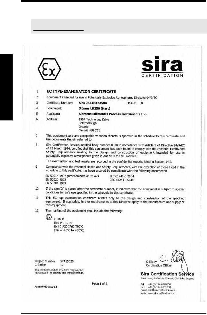
Page 150 SITRANS LR250 (HART) – INSTRUCTION MANUAL 7ML19985JE03
mmmmm
G: ATEX Certificates
Appendix G: ATEX Certificates
ATEX Certificate SIRA 06ATEX2358X
Note: AT EX certificates can be downloaded from the product page of our website at
www.siemens.com/LR250.
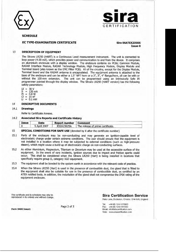
7ML19985JE03 SITRANS LR250 (HART) – INSTRUCTION MANUAL Page 151
mmmmm
G: ATEX Certificates
Page 152 SITRANS LR250 (HART) – INSTRUCTION MANUAL 7ML19985JE03
mmmmm
G: ATEX Certificates

7ML19985JE03 SITRANS LR250 (HART) – INSTRUCTION MANUAL Page 153
mmmmm
G: ATEX Certificates
ATEX Certificate SIRA 08ATEX1301X
CERTIFICATE TO BE ADDED

Page 154 SITRANS LR250 (HART) – INSTRUCTION MANUAL 7ML19985JE03
mmmmm
G: ATEX Certificates

7ML19985JE03 SITRANS LR250 (HART) – INSTRUCTION MANUAL Page 155
mmmmm
G: ATEX Certificates

Page 156 SITRANS LR250 (HART) – INSTRUCTION MANUAL 7ML19985JE03
mmmmm
H: Firmware Revision
Appendix H: Firmware Revision History
Firm-
ware
Rev.
PDM
EDD Rev. Date Changes
1.00.03 1.00.03 25/02/2007 • Initial release
1.01.00 1.01.00 27/072007 •EDD
a)/SIMATIC PDM: View > Display >
Distanceb) correctly reported.
• EDD/SIMATIC PDM: Improved rendering of
the echo profile and TVT.
a) Electronic Device Description
b) See Sensor Mode (2.2.2.) on page 79 for an illustration of Distance.
1.01.01 1.01.01 10/06/2008 • Maintenance release of firmware and
EDDa).
1.01.01 1.01.03 17/06/2008 • The internal EDD revision has been
incremented.
1.02.01 1.02.01 16/12/2008 • AMS EDD Rev. 1.02.01
• Support NAMUR NE 43.
• Harmonization of menu structures and
parameter names across products.
• Display indicates progress towards first
measurement.

7ML19985JE03 SITRANS LR250 (HART) – INSTRUCTION MANUAL Page 157
mmmmm
Glossary
Glossary
accuracy: degree of conformity of a measure to a standard or a true value.
agitator: mechanical apparatus for mixing or aerating. A device for creating turbulence.
algorithm: a prescribed set of well-defined rules or processes for the solution of a problem in a
finite number of steps.
ambient temperature: the temperature of the surrounding air that comes in contact with the
enclosure of the device.
antenna: an aerial which sends out and receives a signal in a specific direction. There are four
basic types of antenna in radar level measurement, horn, parabolic, rod, and waveguide.
attenuation: a term used to denote a decrease in signal magnitude in transmission from one
point to another. Attenuation may be expressed as a scalar ratio of the input magnitude to
the output magnitude or in decibels.
Auto False-Echo Suppression: a technique used to adjust the level of a TVT to avoid the
reading of false echoes. (See TVT.)
Auto False-Echo Suppression Distance: defines the endpoint of the TVT distance. (See TVT.)
This is used in conjunction with auto false echo suppression.
beam width: the angle diametrically subtended by the one-half power limits (-3 dB) of the
microwave beam.
beam spreading: the divergence of a beam as it travels through a medium.
blanking: a blind zone extending away from the reference point plus any additional shield
length.The instrument is programmed to ignore this zone.
capacitance: the property of a system of conductors and dielectrics that permits the storage of
electricity when potential differences exist between the conductors. Its value is
expressed as the ratio of a quantity of electricity to a potential difference, and the unit is a
Farad.
confidence: see Echo Confidence
damping: term applied to the performance of an instrument to denote the manner in which the
measurement settles to its steady indication after a change in the value of the level.
dB (decibel): a unit used to measure the amplitude of signals.

Page 158 SITRANS LR250 (HART) – INSTRUCTION MANUAL 7ML19985JE03
mmmmm
Glossary
derating: to decrease a rating suitable for normal conditions according to guidelines specified
for different conditions.
dielectric: a nonconductor of direct electric current.1)
dielectric constant (dK): the ability of a dielectric to store electrical potential energy under the
influence of an electric field. Also known as Relative Permittivity. An increase in the
dielectric constant is directly proportional to an increase in signal amplitude. The value is
usually given relative to a vacuum /dry air: the dielectric constant of air is 11.
echo: a signal that has been reflected with sufficient magnitude and delay to be perceived in
some manner as a signal distinct from that directly transmitted. Echoes are frequently
measured in decibels relative to the directly transmitted signal.
Echo Confidence: describes the quality of an echo. Higher values represent higher quality.
Echo Threshold defines the minimum value required for an echo to be accepted as valid
and evaluated.
Echo Lock Window: a window centered on an echo in order to locate and display the echo’s
position and true reading. Echoes outside the window are not immediately processed.
Echo Marker: a marker that points to the processed echo.
Echo Processing: the process by which the radar unit determines echoes.
Echo Strength: describes the strength of the selected echo in dB referred to 1 µV rms.
Echo Profile: a graphical display of a processed echo.
false echo: any echo which is not the echo from the desired target. Generally, false echoes are
created by vessel obstructions.
frequency: the number of periods occurring per unit time. Frequency may be stated in cycles
per second.
Hertz (Hz): unit of frequency, one cycle per second. 1 Gigahertz (GHz) is equal to 109 Hz.
HART: Highway Addressable Remote Transducer. An open communication protocol used to
address field instruments.
horn antenna: a conical, horn-shaped antenna which focuses microwave signals. The larger
the horn diameter, the more focused the radar beam.
inductance: the property of an electric circuit by virtue of which a varying current induces an
electromotive force in that circuit or in a neighboring circuit. The unit is a Henry.
microwaves: the term for the electromagnetic frequencies occupying the portion of the radio
frequency spectrum from 1 GHz to 300 GHz.
1) Many conductive liquids/electrolytes exhibit dielectric properties; the relative dielec-
tric constant of water is 80.

7ML19985JE03 SITRANS LR250 (HART) – INSTRUCTION MANUAL Page 159
mmmmm
Glossary
multiple echoes: secondary echoes that appear as double, triple, or quadruple echoes in the
distance from the target echo.
Near Blanking: see Blanking
nozzle: a length of pipe mounted onto a vessel that supports the flange.
parameters: in programming, variables that are given constant values for specific purposes or
processes.
polarization: the property of a radiated electromagnetic wave describing the time-varying
direction and amplitude of the electric field vector.
polarization error: the error arising from the transmission or reception of an electromagnetic
wave having a polarization other than that intended for the system.
propagation factor (pf): where the maximum velocity is 1.0, pf is a value that represents a
reduction in propagation velocity as a result of the wave travelling through a pipe or
medium.
pulse radar: a radar type that directly measures distance using short microwave pulses.
Distance is determined by the return transit time.
radar: radar is an acronym for RAdio Detection And Ranging. A device that radiates
electromagnetic waves and utilizes the reflection of such waves from distant objects to
determine their existence or position.
range: distance between a transmitter and a target.
range extension: the distance below the zero percent or empty point in a vessel.
relative humidity: the ratio of the actual amount of moisture in the atmosphere to the maximum
amount of moisture the atmosphere could hold (which varies depending on the air
temperature).
relative permittivity: see dielectric constant.
repeatability: the closeness of agreement among repeated measurements of the same
variable under the same conditions.
sensor value: the value produced by the echo processing which represents the distance from
sensor reference point to the target. (see Sensor Mode (2.2.2.) on page 79 for an
illustration).
shot: one transmit pulse or measurement.
speed of light: the speed of electromagnetic waves (including microwave and light) in free
space. Light speed is a constant 299, 792, 458 meters per second.
stillpipe: a pipe that is mounted inside a vessel parallel to the vessel wall, and is open to the
vessel at the bottom.

Page 160 SITRANS LR250 (HART) – INSTRUCTION MANUAL 7ML19985JE03
mmmmm
Glossary
stilling-well: see stillpipe.
two wire radar: a low-energy radar. Can be loop powered, analog, intrinsically safe 4 to 20 mA,
or a digital (BUS) transmitter.
TVT (Time Varying Threshold): a time-varying curve that determines the threshold level above
which echoes are determined to be valid.
waveguide antenna: a hollow, metallic tube that transmits a microwave signal to the product
target.

7ML19985JE03 SITRANS LR250 (HART) – INSTRUCTION MANUAL Page 161
mmmmm
Index
Index
A
Abbreviations and Identifications
list 3
access control
remote access 113
activating LR250 31
agitator blade detection
avoiding 92
AMS Device Manager
features 60
analog output
explanation 132
fail signal 8
select 55
signal range 8
simulate via PDM 56
analog output scale
setup 84
approvals 10
Auto False Echo Suppression 130
explanation 130
setup 94
setup via PDM 52
B
beam angle
values 13, 15
blanking (see Near Range) 131
bypass pipe
installation 22
C
cables
requirements 24
Calibration Interval 108
cleaning
instructions 125
CLEF (Constrained Leading Edge Fit)
explanation 128
CLEF range
setup 92
communication
load 8
max. line length 8
conduits
requirements 24
configuration
new device via AMS 61
new device via PDM 41
Quick Start via LUI 36
configuration flag reset 56
D
Damping
explanation 132
Damping Filter
setup 80
data logging
time-based echo profile storage 50
Device Address 113
setting via LUI 39
device description
HART 146
Device Reset 99
device reset
see Master Reset 99
device status
view via PDM 58
Diagnostics 98
dimensions
flanges 16, 18
horn 12, 13, 15
threaded horn 12
threaded horn with extension 12
E
echo confidence
parameter setup 93
echo processing
Process Intelligence 126
process intelligence 126
echo profile
data logging 50
view via LUI 38
view via PDM 58
Echo Profile Utilities 49
echo selection
Algorithm 127
CLEF (Constrained Leading Edge Fit)
128
Position algorithm 127
time varying threshold (TVT) 127
Echo setup
quick access 54
EDD
electronic device description 41
edit mode

Page 162 SITRANS LR250 (HART) – INSTRUCTION MANUAL 7ML19985JE03
mmmmm
Index
handheld programmer 34
key functions 35
electronic device description (EDD) 41
enclosure
opening 24
F
factory defaults
Master Reset 99
Fail-safe
settings 83
Fail-safe Mode
explanation 134
Fail-safe Timer
explanation 134
false echo
see Auto False Echo Suppression 130
Far Range
explanation 131
setup 90
flange markings 16, 18
flange sizes
chart 16, 18
function keys
measurement mode 32
navigation mode 34
H
handheld programmer
edit mode 34
measurement mode 32
navigation 34
HART
device description 146
multidrop mode 149
HART communication
set preambles 56
HART Communications
details 146
HART version 8
hazardous area installations
wiring requirements 25
I
Identifications and Abbreviations
list 3
Index 161
installation
hazardous area requirements 25
internal temperature
monitoring 135
K
key functions
edit mode 35
L
Language 114
LCD display
contrast adjustment 112
echo profile viewing 38
fast mode 111
measurement mode 31
level application example
via LUI 38
lid-lock set screw 24
linearization
via PDM 45
linearization via AMS 64
Local User Interface (LUI) 31
LOE
Fail-safe Mode 134
loop test
simulate analog output 56
loop voltage vs. loop resistance
power supply requirements 26
Loss of Echo (LOE)
explanation 134
LUI (Local User Interface) 31
M
mA output
select analog output 55
maintenance
calibration schedules via PDM 54
cleaning 125
service schedules via PDM 54
maintenance settings 98
see Calibration Interval 108
see Remaining Sensor Lifetime 104
see Service Interval 105
Master Reset
factory defaults 99
factory defaults via AMS 62
measurement range
blanking via Near Range 131
extension via Far Range 131
Measurement Response
explanation 131
mounting
bypass requirements 22
handheld programmer access 22
housing construction 22
nozzle design 21
nozzle location 21
on vessel with obstructions 22

7ML19985JE03 SITRANS LR250 (HART) – INSTRUCTION MANUAL Page 163
mmmmm
Index
stillpipe requirements 22
sunshield recommended 22
multidrop mode 149
N
Near Range
explanation 131
setup 90
O
operating principles 126
P
password protection
via AMS 72
via PDM 58
performance
specifications 7
PIN to unlock
local access 114
pipe sizes
flange mounting 16, 18
polarization reference point 22
power 7
power source
requirements 24
power supply requirements
loop voltage vs. loop resistance 26
principles of operation 126
Process Intelligence 126
process temperature
maximum 135
programmer
handheld 32
programming
adjust parameters via PDM 48
via the handheld programmer 33
propagation factor
values 91
Q
Quick Start Wizard
via LUI 36
via SIMATIC PDM 41
R
reading erratic
troubleshooting 123
reading incorrect
troubleshooting 123
reset
see Master Reset 99
Response Rate
explanation 131
settings 81
S
Scan Device
synchronize parameters via AMS 62
security
local access 114
local access control via AMS 70
local access unlock value 114
password protection via AMS 72
password protection via PDM 58
remote access control 113
remote access control via AMS 70
self-test
device self-test via PDM 55
sensor reference point
flanged horn 14
threaded horn 12
settings
adjust parameters via LUI 33, 34
adjust parameters via PDM 48
sidepipe
see bypass pipe 22
SIMATIC PDM
functions and features 40
Rev. 5.2, SP1 features 41
Rev. 6.0, SP3 features 40
simulate analog output
loop test 56
specifications 7
ambient temperature 9
antenna 8
enclosure 8
environmental 9
performance 7
power 7
pressure 10
process connections 8
process temperature 10
weight 8
startup
transition screen 31
stillpipe
installation 22
stillpipe application
configuring via PDM 47
synchronize parameters
scan device via AMS 62
T
technical support
contact information 3
temperature de-Rating

Page 164 SITRANS LR250 (HART) – INSTRUCTION MANUAL 7ML19985JE03
mmmmm
Index
curves 136
test
loop test 56
threaded connection markings 17, 18
trend
view trend line 57
troubleshooting
communication 117
operation 122
TVT (time varying threshold)
explanation 127
TVT Shaper
manual adjustment via PDM 51
U
unlock value
local access 114
uploads/downloads
accelerated 87, 96
V
vessel shape
selection 86
W
wear
view via PDM 58
wiring
cables 24
connecting HART 25
hazardous areas 25
write protect
local access 114

SITRANS LR 250 (HART) – INSTRUCTION MANUAL Page 165 SITRANS LR 250 (HART) – INSTRUCTION MANUAL 7ML19985JE02
Appendix C: menu chart
LCD menu structure
Page 166 SITRANS LR 250 (HART) – INSTRUCTION MANUAL SITRANS LR 250 (HART) – INSTRUCTION MANUAL 7ML19985JE02
Appendix C: menu chart
LCD menu structure
LEVEL METER
1. QUICK START
1.1 LANGUAGE
1.2 MATERIAL
1.3 RESPONSE RATE
1.4 UNITS
1.5 OPERAT. MODE
1.6 LOW CALIB. PT.
1.7 HIGH CALIB. PT.
1.8 APPLY?
2. SETUP
2.1 DEVICE
2.1.1 HARDWARE REV
2.1.2 FIRMWARE REV
2.1.3 LOADER REV
2.1.4 ORDER OPTION
2.2 SENSOR
2.2.1 UNITS
2.2.2 SENSOR MODE
2.2.3 MATERIAL
2.2.4 DAMPING FILTER
2.3 CALIBRATION
2.3.1 LOW CALIB. PT.
2.3.2 HIGH CALIB. PT.
2.3.3 SENSOR OFFSET
2.4 RATE
2.4.1 RESPONSE RATE
2.4.2 FILL RATE /MIN
2.4.3 EMPTY RATE /MIN
2.5 FAIL-SAFE
2.5.1 MAT. LEV.
2.5.2 TIMER
2.5.3 LEVEL
2.6 ANALOG OUT. SCAL.
2.6.1 CURR. OUT. FUNC.
2.6.2 4 MA SETPOINT
2.6.3 20 MA SETPOINT
2.6.4 MIN. MA LIMIT
2.6.5 MAX. MA LIMIT
2.6.6 MA OUTPUT VALUE
2.7 LINEARIZATION
2.7.1 VOLUME
2.7.1.1 VESSEL SHAPE
2.7.1.2 MAX. VOLUME
2.7.1.3 DIMENS. A
2.7.1.4 DIMENS. L
2.7.2 TABLE 1 – 8
2.7.3 TABLE 9 – 16
2.7.4 TABLE 17 – 24
2.7.5 TABLE 25 – 32
2.8 SIGNAL PROC.
2.8.1 NEAR RANGE
2.8.2 FAR RANGE
2.8.3 PROPAG. FACTOR
2.8.4 ECHO SELECT
2.8.4.1 ALGORITHM
2.8.4.2 POS. DETECT
2.8.4.3 ECHO THRESHOLD
2.8.4.4 CLEF RANGE
2.8.5 SAMPLING
2.8.5.1 ECHO LOCK
2.8.5.2 UP SAMP.
2.8.5.3 DOWN SAMP.
2.8.6 ECHO QUALITY
2.8.6.1 CONFIDENCE
2.8.6.2 ECHO STRENGTH
2.8.6.3 NOISE AVERAGE
2.8.7 TVT SETUP
2.8.7.1 AUTO ECHO SUPP
2.8.7.2 AUTO SUPP RANGE
2.8.7.3 HOVER LEVEL
2.8.7.4 SHAPER MODE
2.8.8 TVT SHAPER
2.8.8.1 BRKPT. 1-9
2.8.8.2 BRKPT. 10-18
2.8.8.3 BRKPT. 19-27
2.8.8.4 BRKPT. 28-36
2.8.8.5 BRKPT. 37-40
2.8.9 MEAS. VALUES
2.8.9.1 LEVEL MEAS.
2.8.9.2 SPACE MEAS.
2.8.9.3 DISTANCE MEAS.
2.8.9.4 VOLUME MEAS.
3. DIAGNOSTICS
3.1 ECHO PROFILE
3.2 ELECT. TEMP.
3.2.1 CURR. INTERN. TEM..
3.2.2 HIGHEST VALUE.
3.2.3 LOWEST VALUE.
4. SERVICE
4.1 MASTER RESET
4.2 REMAIN. DEV. LIFE
4.2.1 LIFETIME EXPECTE..
4.2.2 TIME IN OPER..
4.2.3 REMAIN. LIFETIM..
4.2.4 REMINDER ACTIV.
4.2.5 REMIND. 1 (REQ)
4.2.6 REMIND. 2 (DEM)
Notes:
• In Navigation mode ARROW keys navigate the menu in the
direction of the arrow..
• See
Parameter Reference
on page 78
for detailed information and
instructions.
2. SETUP (cont’d)

7ML19985JE03 SITRANS LR250 (HART) – INSTRUCTION MANUAL Page 167
mmmmm
LCD menus
4.2.7 MAINT STAT
4.2.8 ACK STATUS
4.2.9 ACK
4.3 REMAIN. SENS. LIFE
4.3.1 LIFETIME EXPECTE..
4.3.2 TIME IN OPER..
4.3.3 REMAIN. LIFETIME
4.3.4 REMINDER ACTIV.
4.3.5 REMIND. 1 (REQ)
4.3.6 REMIND. 2 (DEM)
4.3.7 MAINT STAT
4.3.8 ACK STATUS
4.3.9 ACK
4.4 SERVICE SCHED.
4.4.1 SERV. INTERVAL
4.4.2 TIME LAST SERV.
4.4.3 TIME NEXT SERV.
4.4.4 REMINDER ACTIV.
4.4.5 REMIND. 1 (REQ)
4.4.6 REMIND. 2 (DEM)
4.4.7 MAINT STAT
4.4.8 ACK STATUS
4.4.9 ACK
4.5 CALIB. SCHED.
4.5.1 CALIB. INTERVAL
4.5.2 TIME LAST CALIB.
4.5.3 TIME NEXT CALIB.
4.5.4 REMINDER ACTIV.
4.5.5 REMIND. 1 (REQ)
4.5.6 REMIND. 2 (DEM)
4.5.7 MAINT STAT
4.5.8 ACK STATUS
4.5.9 ACK
4.6 MANUF. DATE
4.7 POWERED HOURS
4.8 POWERON RESETS
4.9 LCD FAST MODE
4.10 LCD CONTRAST
4.11 MEM. TEST
5. COMMUNICATION
5.1 DEVICE ADDRESS
6. SECURITY
6.1 REMOTE ACCESS
6.1.1 ACCESS CONTROL
6.2 LOCAL ACCESS
6.2.1 WRITE PROTECT
6.2.2 PIN TO UNLOCK
7. LANGUAGE
4. SERVICE
(cont’d)

Page 168 SITRANS LR250 (HART) – INSTRUCTION MANUAL 7ML19985JE03
mmmmm
LCD menus
Notes

*7ml19985JE03* Rev. 3.0
www.siemens.com/processautomation
Siemens Milltronics Process Instruments Inc.
1954Technology Drive, P.O. Box 4225
Peterborough, ON, Canada K9J 7B1
Tel: (705) 745-2431 Fax: (705) 741-0466
Email: techpubs.smpi@siemens.com
Siemens Milltronics Process Instruments Inc. 2009
Subject to change without prior notice
Printed in Canada