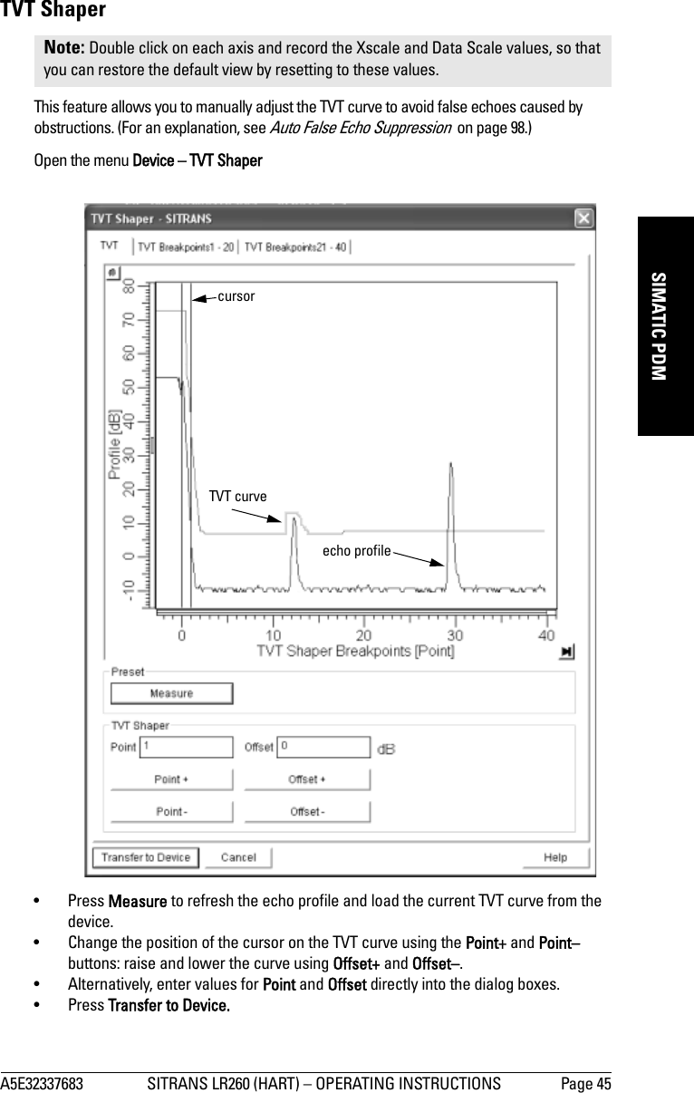
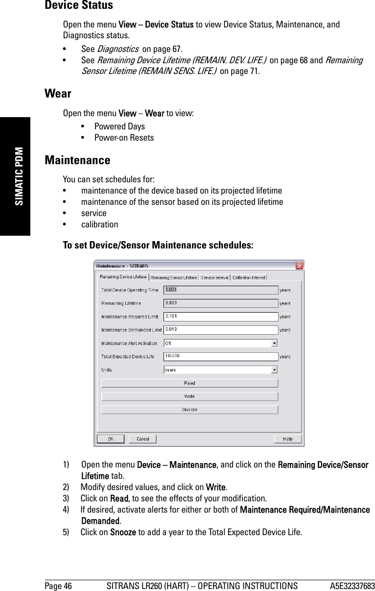
Siemens Canada Siemens Milltronics Process Instruments LR260 SITRANS LR260 Level Probing Radar User Manual LR260 HA EN 001 AA
Siemens Canada Ltd. - Siemens Milltronics Process Instruments SITRANS LR260 Level Probing Radar LR260 HA EN 001 AA
Contents
User Manual 1
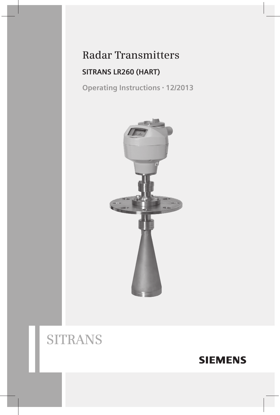

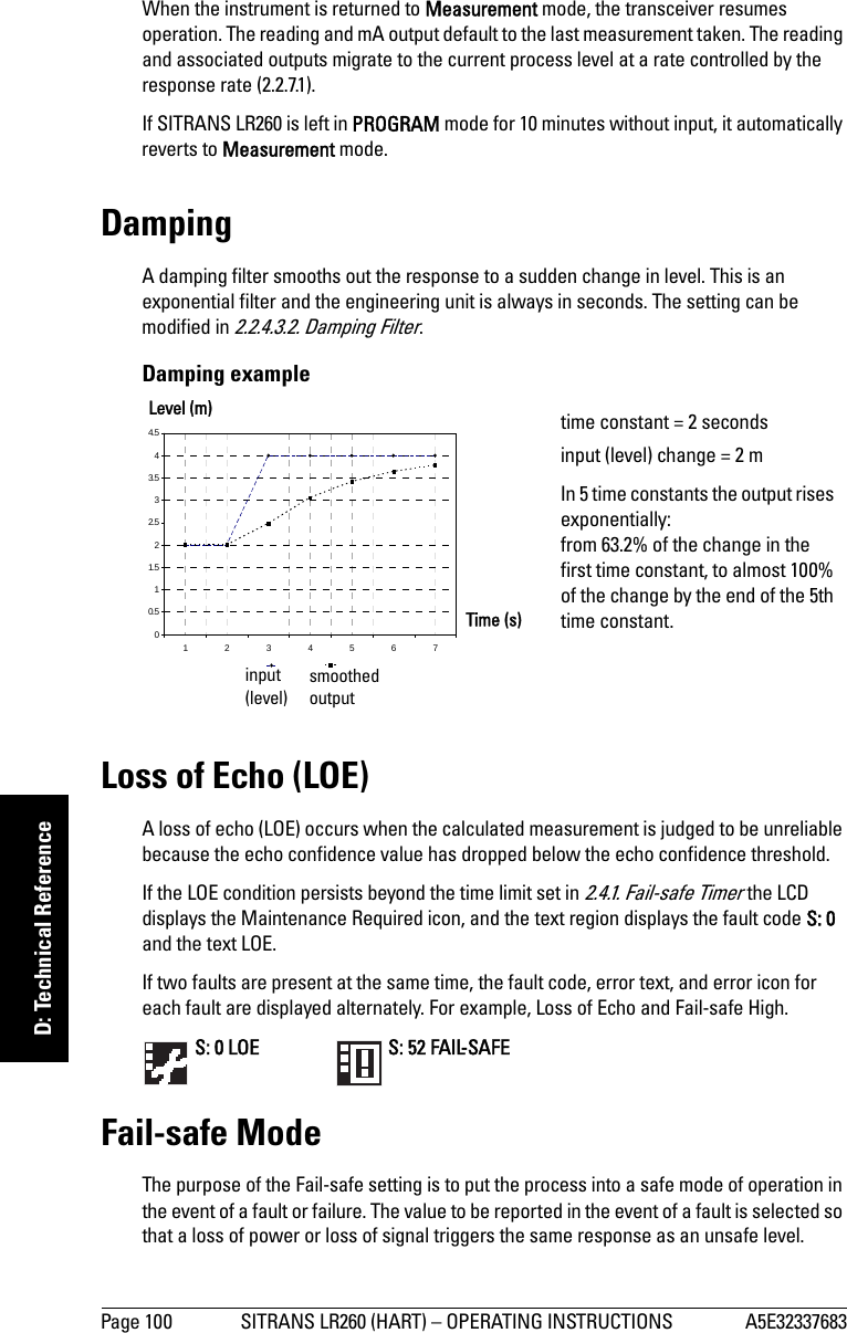
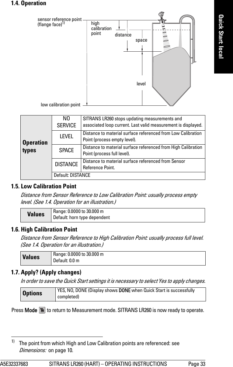
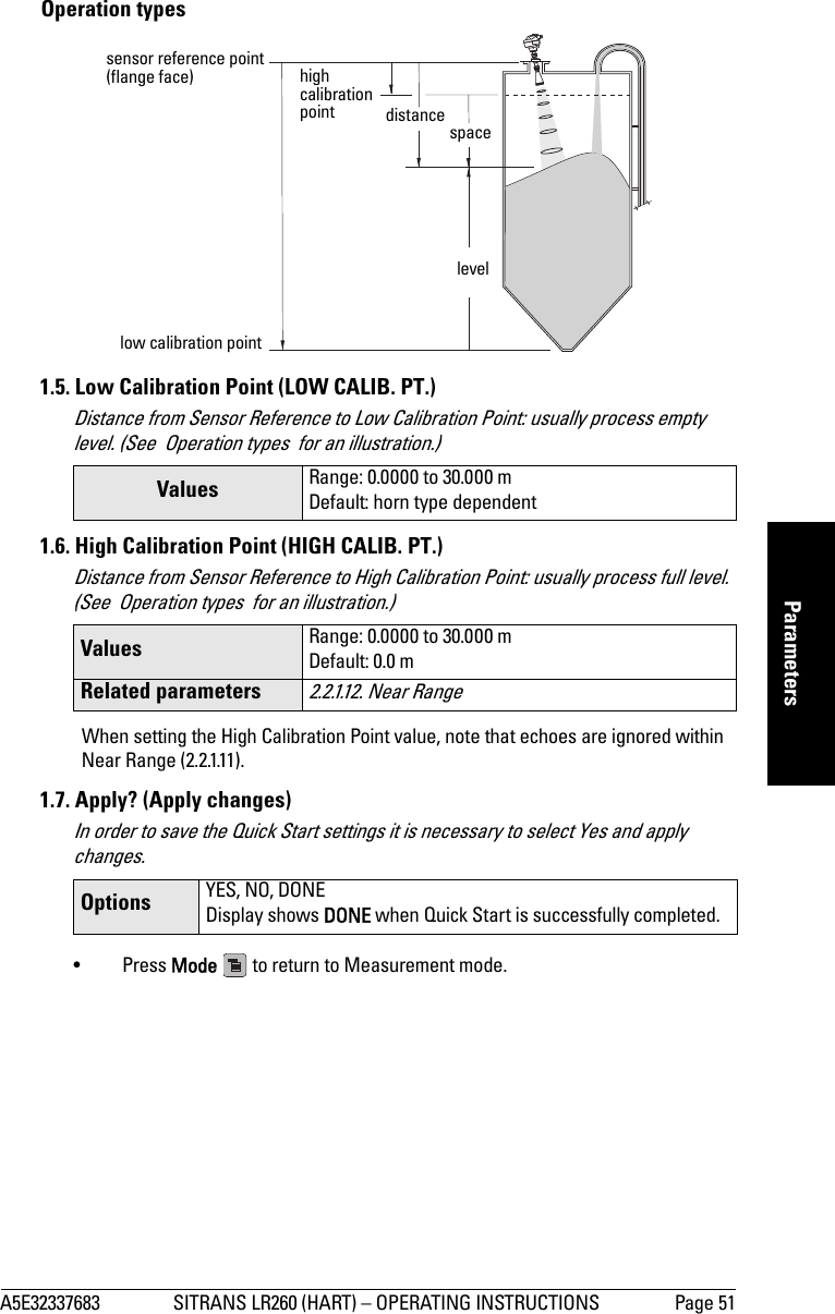
![Page 16 SITRANS LR260 (HART) – OPERATING INSTRUCTIONS A5E32337683mmmmmInstallationEasy Aimer1. Holding the electronics enclosure firmly, loosen the Easy Aimer ball locking bolts and gently reposition the enclosure.2. Direct SITRANS LR260 so the horn antenna is pointed at an angle perpendicular to the material surface, if possible. (As a guide, aim the beam at a point approximately 2/3 of the way across the tank diameter.)3. When the desired position is reached, re-tighten the 5 bolts to 15-23 Nm (11 to 17 Lbf-ft).Note: When the Easy Aimer ball is loosened, the device is free to tilt to a maximum of 30°.top clamping plate (upper socket)bottom clamping plate (lower socket)customer gasket as required [recommended thickness 1.5 to 1.8 mm (0.06 to 0.07")]customer mounting plate, as requiredø 4" (102 mm) min., central opening30° max.285 mm (11.22") 0.38" (10 mm)Easy Aimer ball locking boltsEasy Aimer](https://usermanual.wiki/Siemens-Canada-Siemens-Milltronics-Process-Instruments/LR260.User-Manual-1/User-Guide-2338061-Page-22.png)
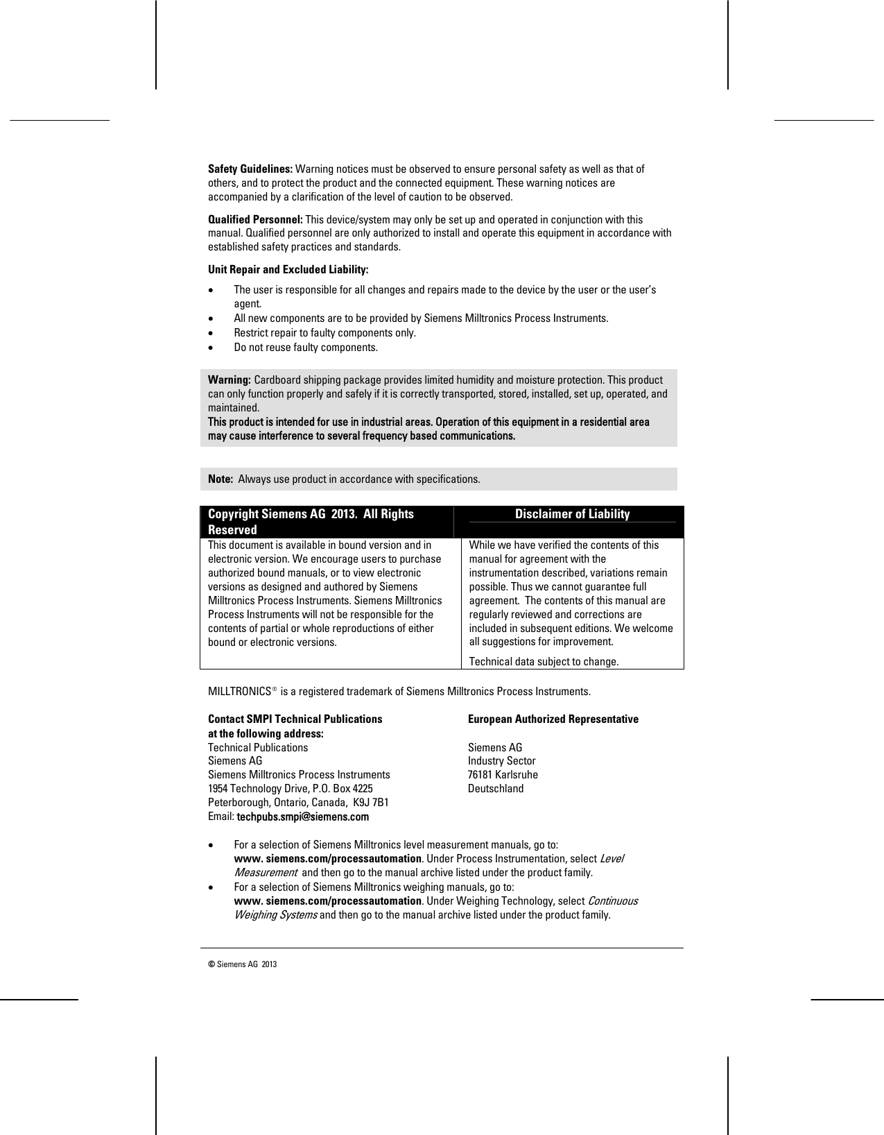
![A5E32337683 SITRANS LR260 (HART) – OPERATING INSTRUCTIONS Page 21mmmmmWiring1. Strip the cable jacket for approximately 70 mm (2.75") from the end of the cable, and thread the wires through the gland1).2. Connect the wires to the terminals as shown: the polarity is identified on the terminal block.3. Ground the instrument according to local regulations.4. Tighten the gland to form a good seal.Connecting HART2)3)1) If cable is routed through conduit, use only approved suitable-size hubs for waterproof applications.2) Depending on the system design, the power supply may be separate from the PLC, or integral to it.3) Loop resistance (total of cable resistance plus 250 Ohm [resistor]) must be less than 550 Ohm for the device to function properly.cable shield(if used)active PLCHART modemSITRANS LR260power supply2Typical PLC/mA configuration with HARTR= 250 3HART communicator](https://usermanual.wiki/Siemens-Canada-Siemens-Milltronics-Process-Instruments/LR260.User-Manual-1/User-Guide-2338061-Page-27.png)
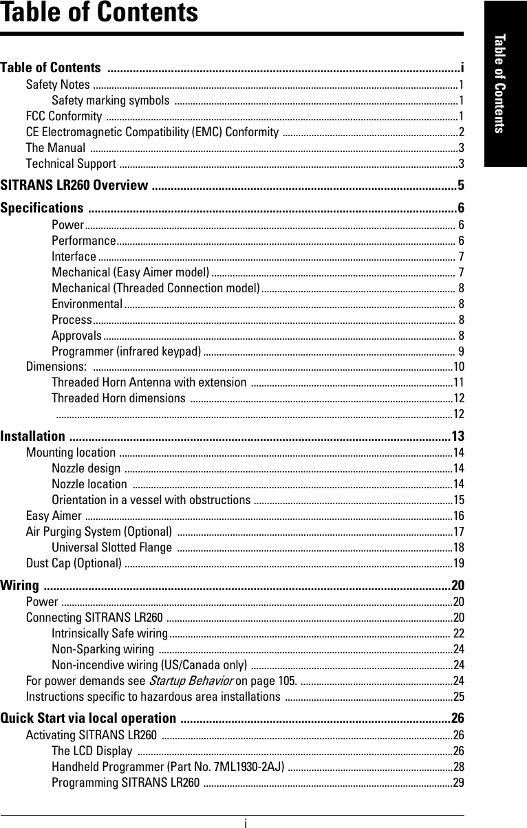
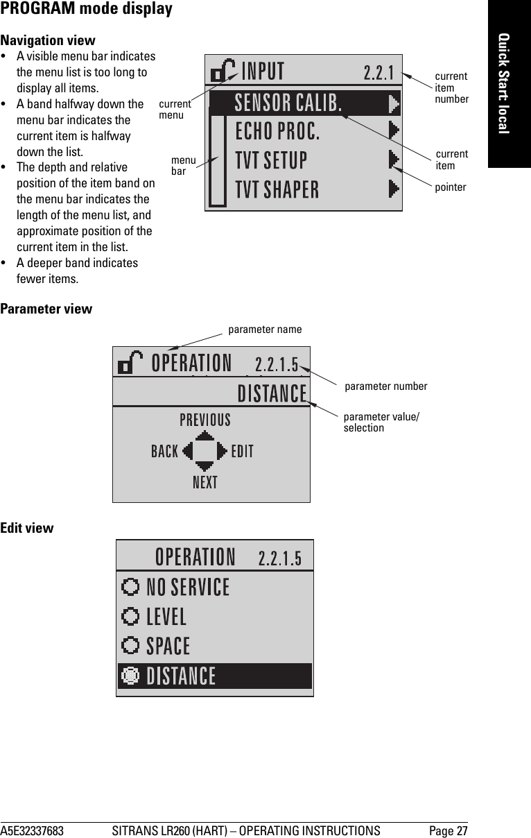
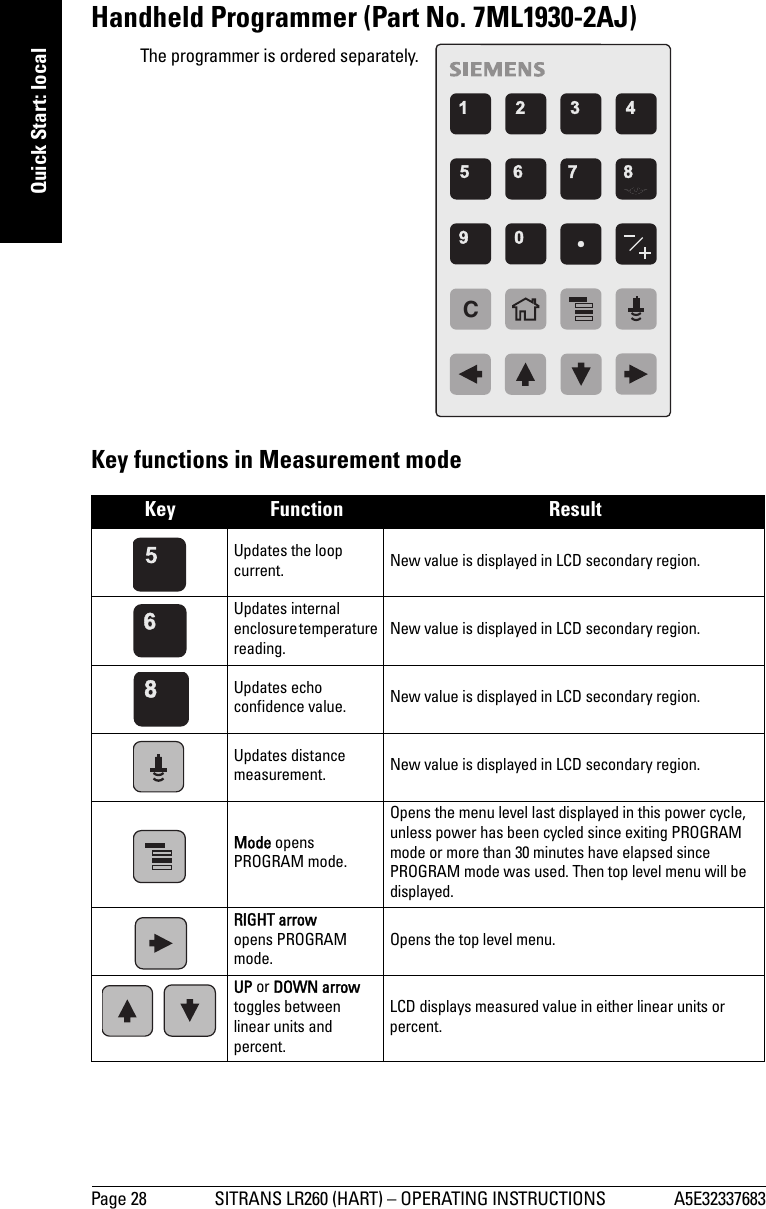
![Page 26 SITRANS LR260 (HART) – OPERATING INSTRUCTIONS A5E32337683mmmmmQuick Start: localQuick Start via local operationSITRANS LR260 carries out its level measurement tasks according to settings made via parameters. The settings can be modified locally via the Local User Interface (LUI) which consists of an LCD display and a handheld programmer. A Quick Start Wizard provides an easy step-by-step guide to help you configure the device for a simple application. There are two ways to access the wizard:•7-step Quick Start Wizard via the handheld programmer on page 32•4-step Quick Start Wizard via SIMATIC PDM on page 37 for programming via SIMATIC PDM.For more complex setups, see Appendix E: Application Example on page 107, and for the complete range of parameters, see Parameter Reference on page 49.Activating SITRANS LR260Power up the instrument. SITRANS LR260 automatically starts up in Measurement mode. Press Mode to toggle between Measurement and Program Mode.The LCD DisplayMeasurement mode 1)Normal operationFault present1) In response to a key press request. For details, see Key functions in Measurement mode on page 28.M[]LEVEL21.40 °CDATA EXCH.18.911 – toggle indicator for linear units or %2 – selected operation: level, space, or distance3 – measured value (level, space, or distance)4 – units5 – bar graph indicates level6 – secondary region indicates on request1 electronics temperature, echo confidence, loop current, or distance7 – text area displays status messages 8 – device status indicator67813425S: 0 LOE7 – text area displays a fault code and an error message8 – service required icon appears](https://usermanual.wiki/Siemens-Canada-Siemens-Milltronics-Process-Instruments/LR260.User-Manual-1/User-Guide-2338061-Page-32.png)
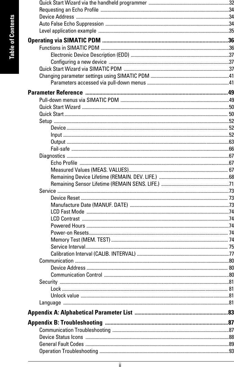
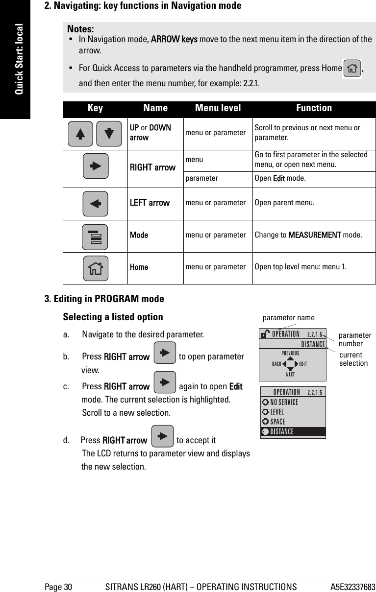
![A5E32337683 SITRANS LR260 (HART) – OPERATING INSTRUCTIONS Page 29mmmmmQuick Start: localProgramming SITRANS LR260Change parameter settings and set operating conditions to suit your specific application. •See Operating via SIMATIC PDM on page 36 for remote operation.Programming via the handheld programmerParameter menusParameters are identified by name and organized into function groups, then arranged in a 5-level menu structure (seeLCD menu structure on page 121).• For the complete list of parameters with instructions, see Parameter Reference on page 49.1. Enter PROGRAM mode• Point the programmer at the display (from a maximum distance of 500 mm [1.6 ft.]).•RIGHT arrow activates PROGRAM mode and opens menu level 1. •Mode opens the menu level last displayed in PROGRAM mode within the last 30 minutes, or menu level 1 if power has been cycled since then.Notes: • While the device is in PROGRAM mode, the output remains fixed and does not respond to changes in the device.• Do not use the handheld programmer at the same time as SIMATIC PDM or erratic operation may result.• SITRANS LR260 automatically returns to Measurement mode after a period of inactivity in PROGRAM mode (between 15 seconds and 10 minutes, depending on the menu level). Note: For the complete list of parameters with instructions, see Parameter Reference on page 49.1. QUICK START2. SETUP2.1. DEVICE2.2. INPUT2.2.1. SENSOR CALIB.2.2.4. ECHO PROC.Note: In Navigation mode ARROW keys move to the next menu item in the direction of the arrow. displayhandheld programmer (ordered separately)max. 500 mm(1.6 ft)](https://usermanual.wiki/Siemens-Canada-Siemens-Milltronics-Process-Instruments/LR260.User-Manual-1/User-Guide-2338061-Page-35.png)
![Page 32 SITRANS LR260 (HART) – OPERATING INSTRUCTIONS A5E32337683mmmmmQuick Start: localQuick Start Wizard via the handheld programmer1. Quick Starta. Point the programmer at the display (from a maximum distance of 500 mm [1.6 ft.]), then press RIGHT arrow to activate PROGRAM mode and open menu level 1. b. Press RIGHT arrow twice to navigate to menu item 1.1 and open parameter view. c. Press RIGHT arrow to open Edit mode or DOWN arrow to accept default values.d. To change a setting, scroll to the desired item or key in a new value.e. After modifying a value, press RIGHT arrow to accept it and press DOWN arrow to move to the next item. f. The Quick Start Wizard settings are inter-related and changes apply only after you click on Yes in Apply? at the end of the Quick Start steps.1.1. Application Type1.2. Response RateSets the reaction speed of the device to measurement changes in the target range.Use a setting just faster than the maximum filling or emptying rate (whichever is greater). 1.3. UnitsSelect the units for the Quick Start variables (high and low calibration point, and level, distance, or space)Notes: • The Quick Start Wizard settings are inter-related and changes apply only after you click on Yes in Apply?at the end of the Quick Start steps.• Do not use the Quick Start wizard to modify individual parameters: see instead Parameter Reference on page 49 (perform customization for your application only after the Quick Start has been completed).OptionsSTEEL Silo constructionCONCRETEDefault: STEELOptionsSLOW 0.1 m/minuteMED 1.0 m/minuteFAST 10.0 m/minuteDefault: FASTOptions M, CM, MM, FT, INDefault: M](https://usermanual.wiki/Siemens-Canada-Siemens-Milltronics-Process-Instruments/LR260.User-Manual-1/User-Guide-2338061-Page-38.png)

![A5E32337683 SITRANS LR260 (HART) – OPERATING INSTRUCTIONS Page 87mmmmmB: TroubleshootingAppendix B: TroubleshootingCommunication TroubleshootingGenerally:1. Check the following:• There is power at the instrument• The LCD shows the relevant data you are expecting• The device can be programmed using the hand programmer2. Verify that the wiring connections are correct.3. Check that the device address is correctly set.4. If you continue to experience problems, go to our website at: . www.siemens.com/processautomation, and check the FAQs for SITRANS LR260, or contact your local Siemens Milltronics representative.Specifically:1. If you try to set a SITRANS LR260 parameter via remote communications, but the parameter remains unchanged:• Some parameters can only be changed when the device is not scanning. Try putting the device in PROGRAM mode using the operating mode function.• Try setting the parameter from the keypad. (First make sure that the lock parameter [6.1] is set to the unlock value.)• The communications control parameter 5.2 must be set to Read/Write to allow you to write parameters to SITRANS LR260.2. If you see unanticipated displays, for example:• PROGRAM mode displayed instead of Measurement mode• the wrong parameter displayed in response to a command• a parameter displayed in response to no commandmake sure no infrared-capable device is close to SITRANS LR260. Any device with infrared capabilities (laptops, cell phones, PDAs) can cause interference which simulates a command to the SITRANS LR260, potentially causing it to switch modes or to change a parameter.3. If the operation is erratic, make sure the Hand Programmer is not being used at the same time as SIMATIC PDM.](https://usermanual.wiki/Siemens-Canada-Siemens-Milltronics-Process-Instruments/LR260.User-Manual-1/User-Guide-2338061-Page-93.png)