Siemens Canada Siemens Milltronics Process Instruments LR260 SITRANS LR260 Level Probing Radar User Manual LR260 PA EN 001 AA
Siemens Canada Ltd. - Siemens Milltronics Process Instruments SITRANS LR260 Level Probing Radar LR260 PA EN 001 AA
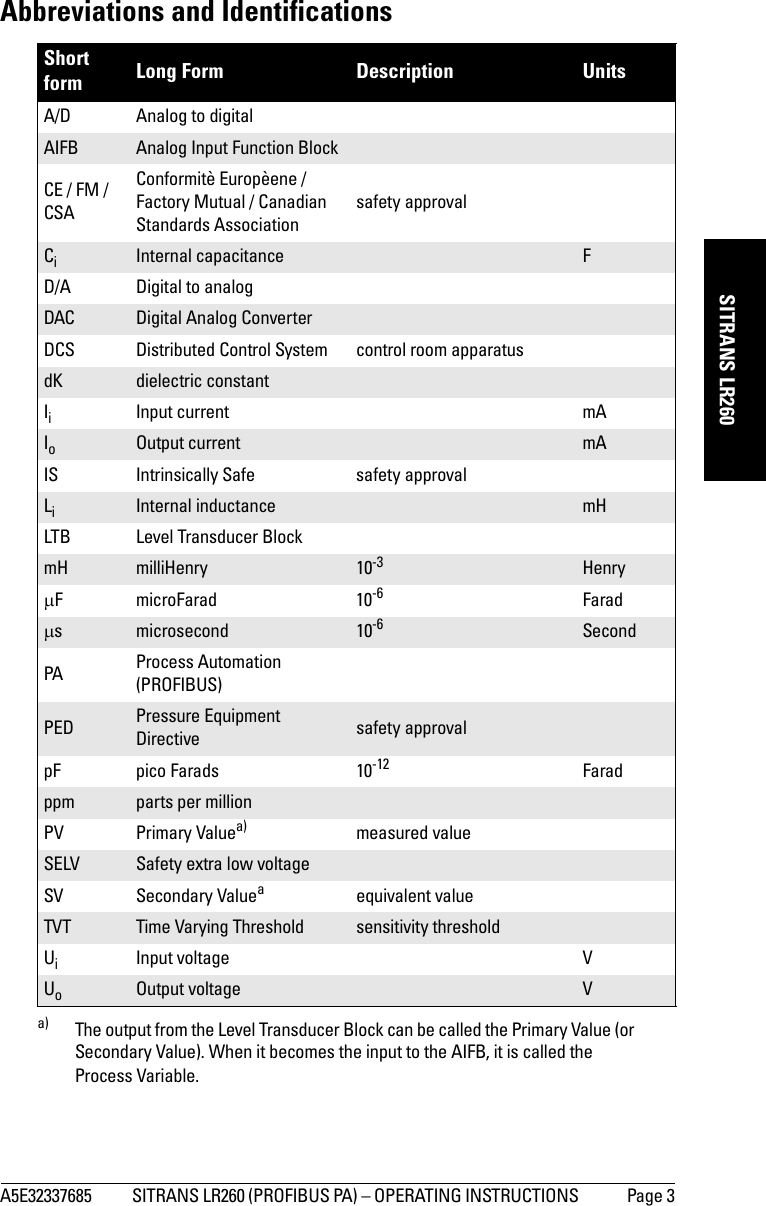
Contents
User Manual 2
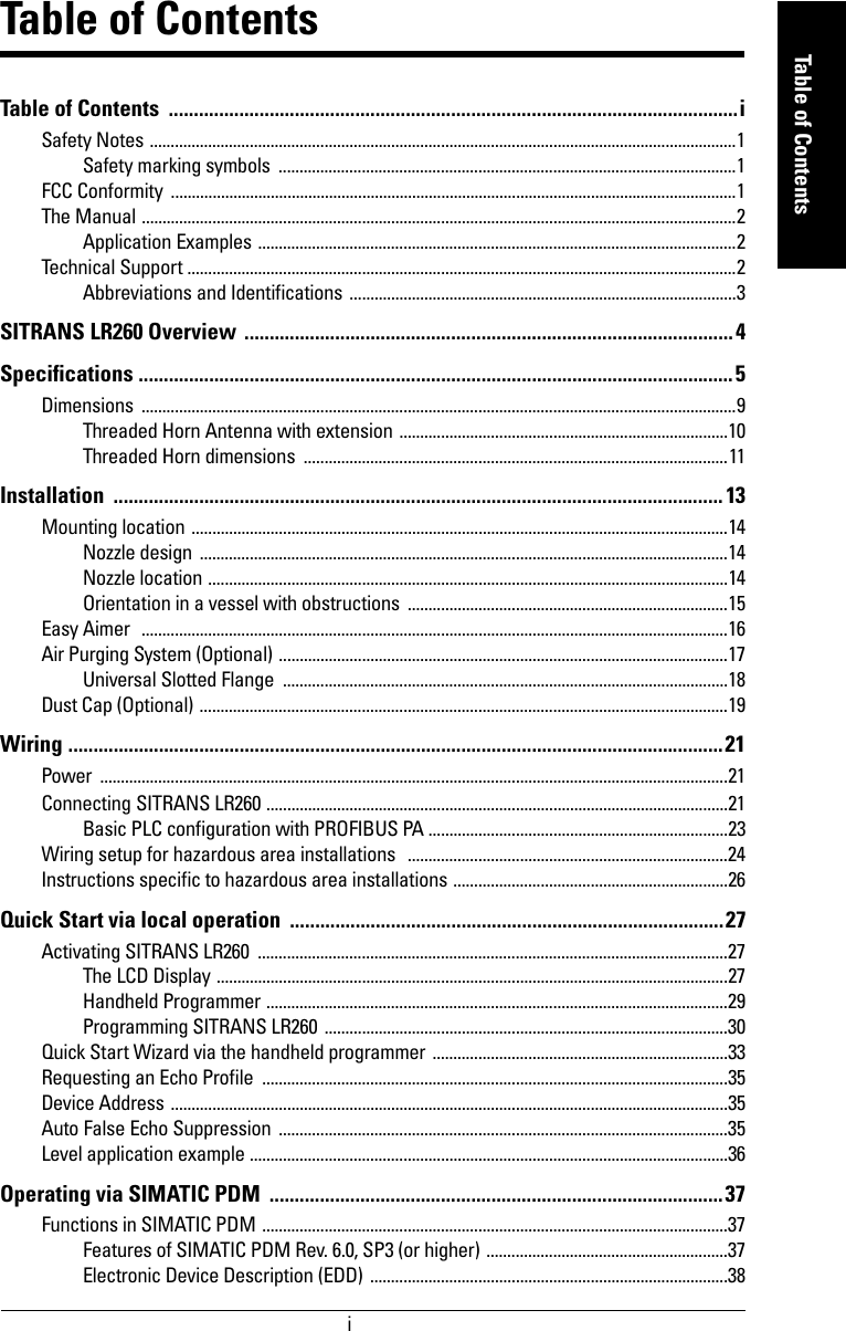


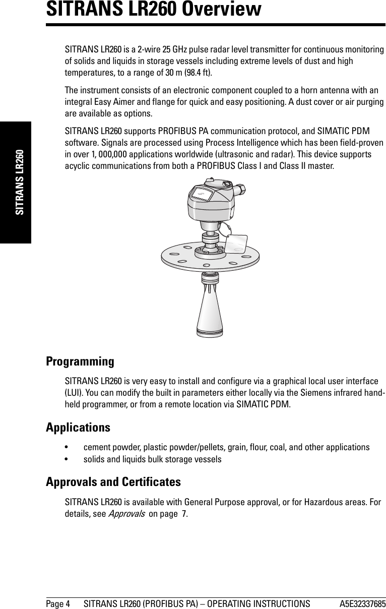

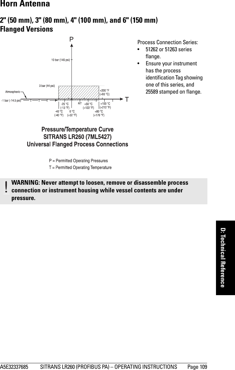
![Page 16 SITRANS LR260 (PROFIBUS PA) – OPERATING INSTRUCTIONS A5E32337685mmmmmInstallationEasy Aimer 1. Holding the electronics enclosure firmly, loosen the Easy Aimer ball locking bolts and gently reposition the enclosure.2. Direct SITRANS LR260 so the horn antenna is pointed at an angle perpendicular to the material surface, if possible. (As a guide, aim the beam at a point approximately 2/3 of the way across the tank diameter.)3. When the desired position is reached, re-tighten the 5 bolts to 15-23 Nm (11 to 17 Lbf-ft).Note: When the Easy Aimer ball is loosened, the device is free to tilt to a maximum of 30°.285 mm (11.22") 0.38" (10 mm)Easy Aimer ball locking boltstop clamping plate (upper socket)bottom clamping plate (lower socket)customer gasket as required [recommended thickness 1.5 to 1.8 mm (0.06 to 0.07")]customer mounting plate, as requiredø 4" (102 mm) min., central opening30° max.Easy Aimer](https://usermanual.wiki/Siemens-Canada-Siemens-Milltronics-Process-Instruments/LR260.User-Manual-2/User-Guide-2338054-Page-22.png)


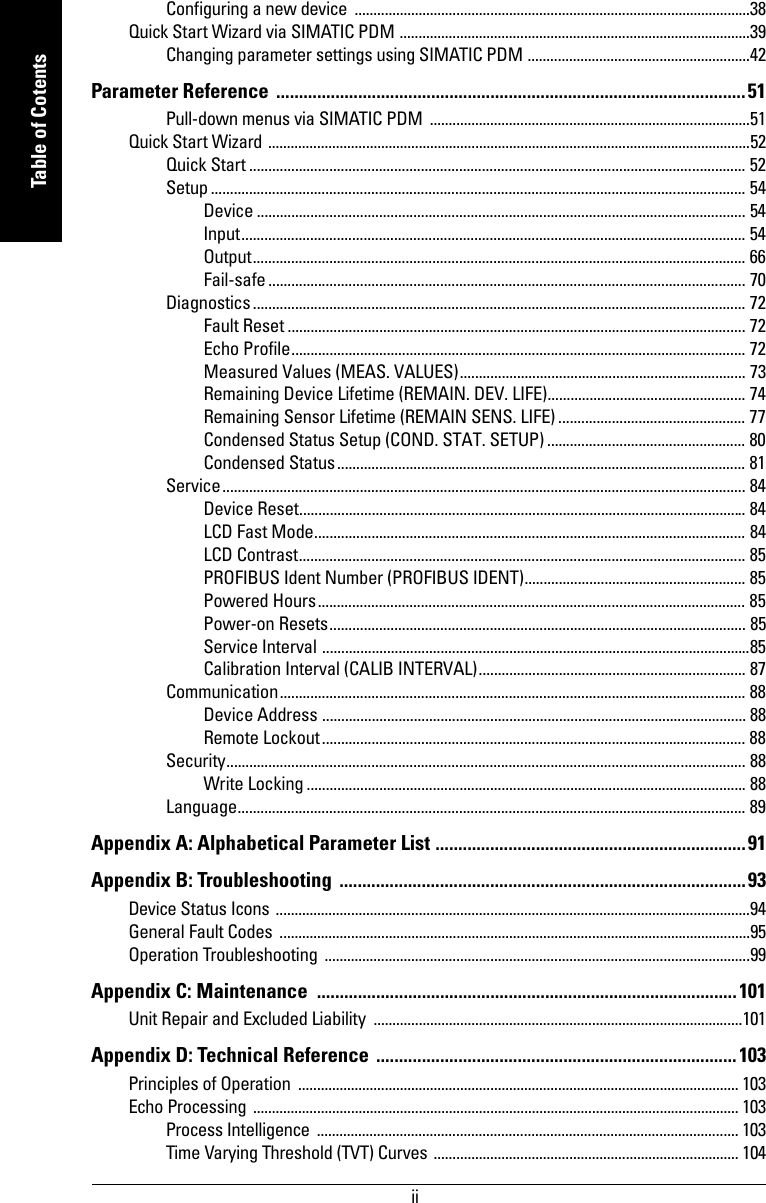
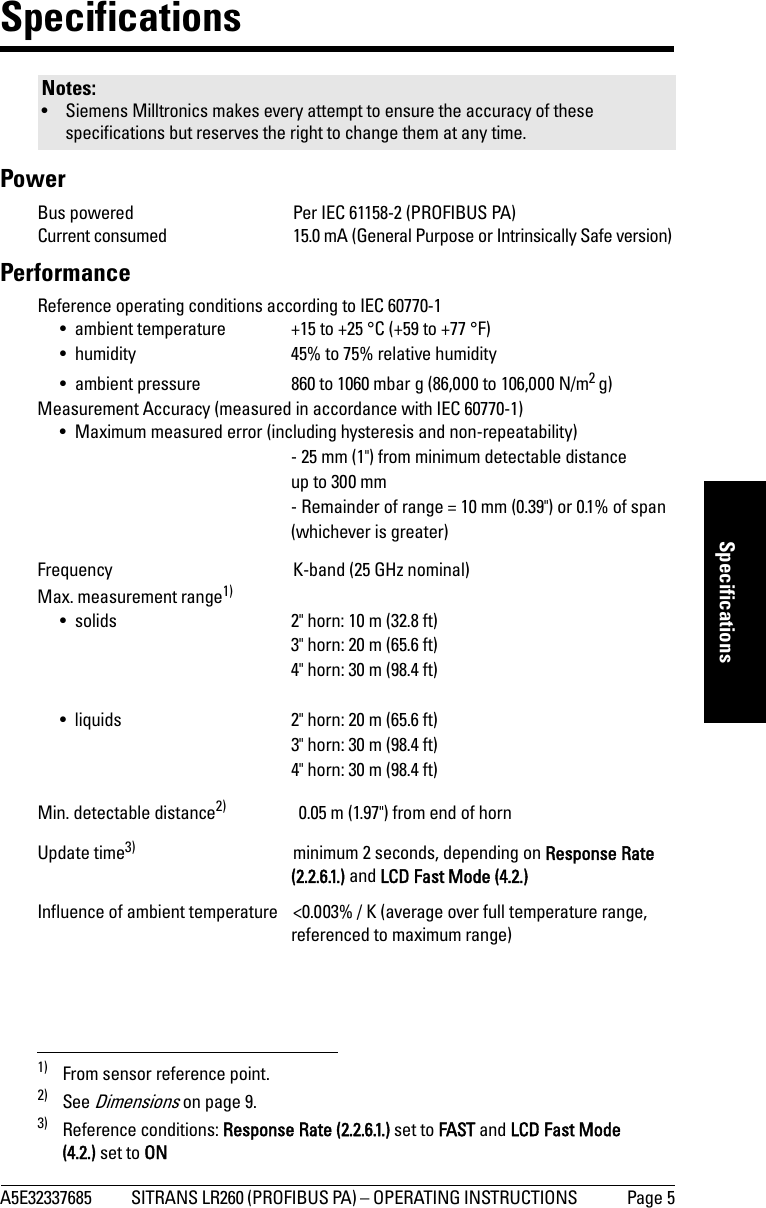
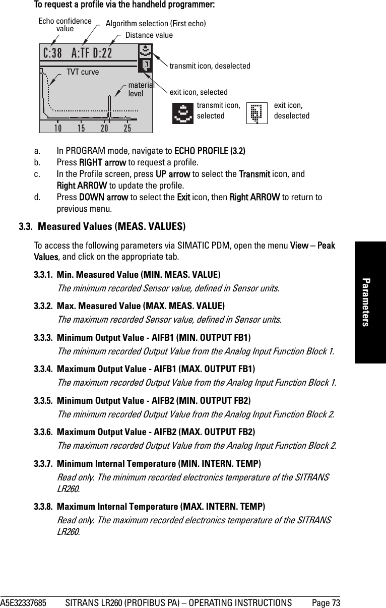
![A5E32337685 SITRANS LR260 (PROFIBUS PA) – OPERATING INSTRUCTIONS Page 27mmmmmQuick Start: localQuick Start via local operationSITRANS LR260 carries out its level measurement tasks according to settings made via parameters. The settings can be modified locally via the Local User Interface (LUI) which consists of an LCD display and a handheld programmer. A Quick Start Wizard provides an easy step-by-step guide to help you configure the device for a simple application. There are two ways to access the wizard:•7-step Quick Start Wizard via the handheld programmer on page 33•4-step Quick Start Wizard via SIMATIC PDM on page 39For more complex setups, see Appendix E: Application Example on page 111, and for the complete range of parameters see Parameter Reference on page 51.Activating SITRANS LR260Power up the instrument. SITRANS LR260 automatically starts up in Measurement mode. Press Mode to toggle between Measurement and Program Mode.1)The LCD DisplayMeasurement mode Normal operationFault present1) In response to a key press request. For details, see Key functions in Measurement mode on page 29.M[]AIFB 121.40 °CNO DATA EXCH.18.911 – toggle indicator for AIFB 1 or AIFB 22 – identifies which AIFB is source of displayed value3 – measured value (level, space, or distance)4 – units5 – bar graph indicates level6 – secondary region indicates on request1 electronics temperature, echo confidence, or distance7 – text area displays status messages 8 – device status indicator67813425S: 0 LOE7 – text area displays a fault code and an error message8 – service required icon appears](https://usermanual.wiki/Siemens-Canada-Siemens-Milltronics-Process-Instruments/LR260.User-Manual-2/User-Guide-2338054-Page-33.png)
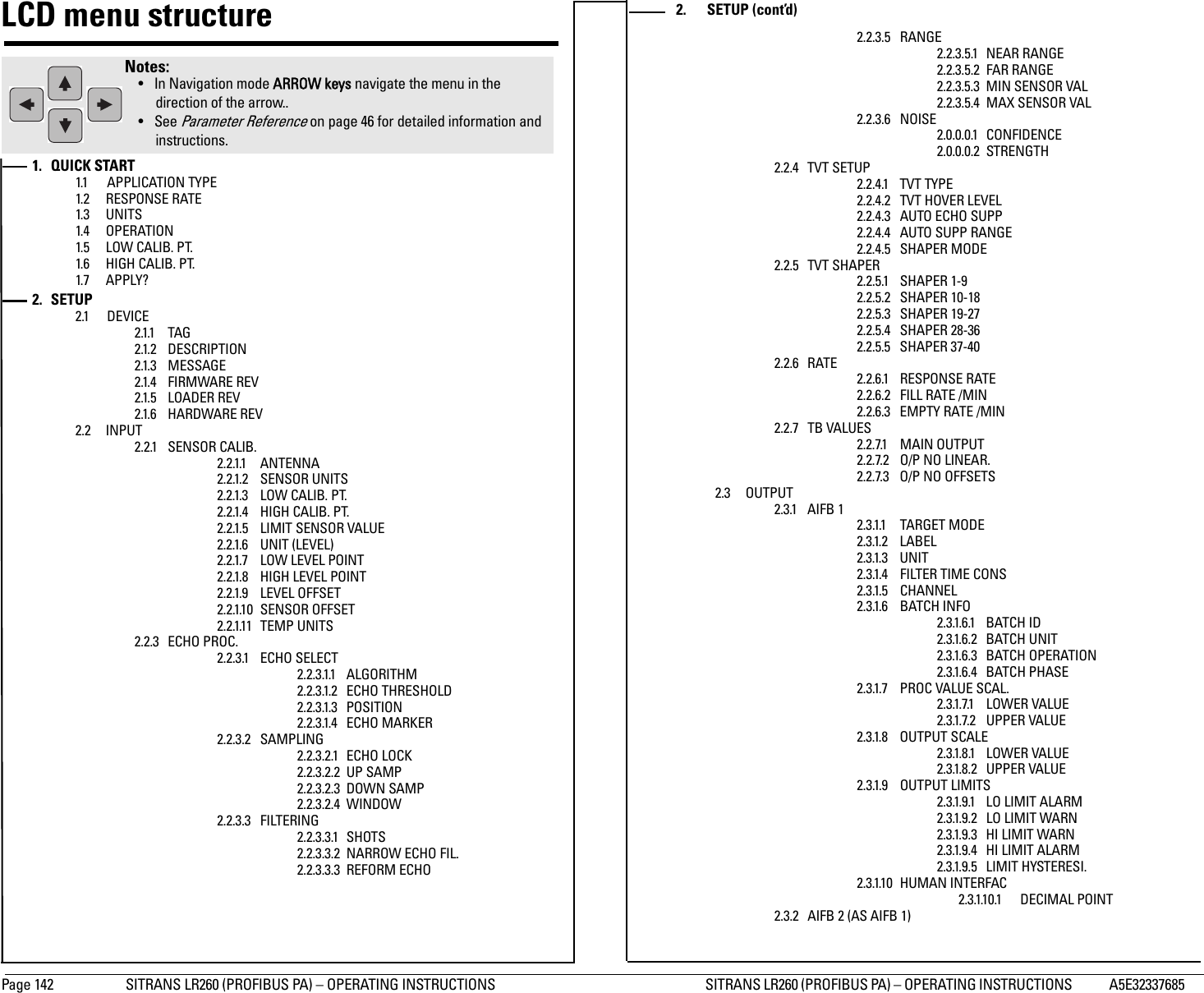
![Page 30 SITRANS LR260 (PROFIBUS PA) – OPERATING INSTRUCTIONS A5E32337685mmmmmQuick Start: localProgramming SITRANS LR260Change parameter settings and set operating conditions to suit your specific application. •See Operating via SIMATIC PDM on page 37 for remote operation.Programming via the handheld programmerParameter menusParameters are identified by name and organized into function groups, then arranged in a 5-level menu structure (seeLCD menu structure on page 141).• For the complete list of parameters with instructions, see Parameter Reference on page 51.1. Enter PROGRAM mode• Point the programmer at the display (from a maximum distance of 500 mm [1.64 ft]).•RIGHT arrow activates PROGRAM mode and opens menu level 1. •Mode opens the menu level last displayed in PROGRAM mode within the last 30 minutes, or menu level 1 if power has been cycled since then.Note: While the device is in PROGRAM mode the output remains active and continues to respond to changes in the device.Notes: • The Quick Start wizard settings are inter-related and changes apply only after you click on Apply at the end of the Quick Start steps.• Do not use the Quick Start wizard to modify individual parameter: see insteadParameter Reference on page 51. • SITRANS LR260 automatically returns to Measurement mode after a period of inactivity in PROGRAM mode (between 15 seconds and 10 minutes, depending on the menu level).1. QUICK START2. SETUP2.1. DEVICE2.2. INPUT2.2.1. SENSOR CALIB.2.2.8. ECHO PROC.Note: In Navigation mode, ARROW keys move to the next menu item in the direction of the arrow. displayhandheld programmer Max. 500 mm(1.64 ft)](https://usermanual.wiki/Siemens-Canada-Siemens-Milltronics-Process-Instruments/LR260.User-Manual-2/User-Guide-2338054-Page-36.png)
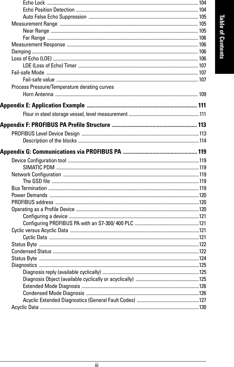
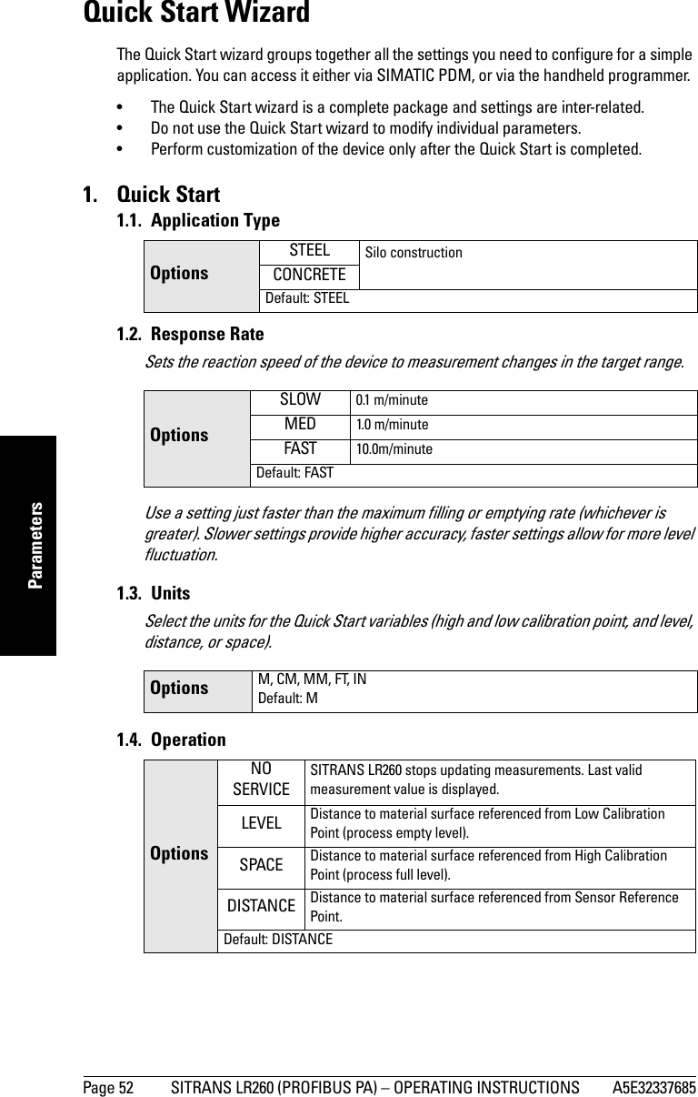
![A5E32337685 SITRANS LR260 (PROFIBUS PA) – OPERATING INSTRUCTIONS Page 33mmmmmQuick Start: localQuick Start Wizard via the handheld programmer1. Quick Starta. Point the programmer at the display (from a maximum distance of 500 mm [1.64 ft]), then press RIGHT arrow to activate PROGRAM mode and open menu level 1.b. Press RIGHT arrow twice to navigate to menu item 1.1 and open parameter view. c. Press RIGHT arrow to open Edit mode or DOWN arrow to accept default values and move directly to the next item.d. To change a setting, scroll to the desired item or key in a new value.e. After modifying a value, press RIGHT arrow to accept it and press DOWN arrow to move to the next item. 1.1. Application Type1.2. Response RateSets the reaction speed of the device to measurement changes in the target range.Use a setting just faster than the maximum filling or emptying rate (whichever is greater). 1.3. UnitsSelect the units for the Quick Start variables (high and low calibration point, and level, distance, or space)Notes: • The Quick Start Wizard is a complete package and the settings are inter-related.• Do not use the Quick Start wizard to modify individual parameters: see instead Parameter Reference on page 51 (perform customization for your application after the quick start has been completed).OptionsSTEEL Silo constructionCONCRETEDefault: STEELOptionsSLOW 0.1 m/minuteMED 1.0 m/minuteFAST 10.0 m/minuteDefault: FASTOptions M, CM, MM, FT, INDefault: M](https://usermanual.wiki/Siemens-Canada-Siemens-Milltronics-Process-Instruments/LR260.User-Manual-2/User-Guide-2338054-Page-39.png)
![Page 46 SITRANS LR260 (PROFIBUS PA) – OPERATING INSTRUCTIONS A5E32337685mmmmmSIMATIC PDMTrendOpen the menu View – TrendSimulationSimulate Analog Input to AIFB1 or AIFB2Allows you to input a simulated value in order to test the functioning of the Analog Input Function Blocks.1. Open the menu Device – Simulation, and select the desired function block.2. Enable simulation.Click on Transfer.3. Enter a value, quality, status, and click on Transfer. The LCD displays the substitute value.4. After simulation is complete, disable simulation.Note: Record the default X-Scale (horizontal axis) and Data Scale (vertical axis) values so that you can restore the default view by resetting to these values.Note: The Simulation parameter influences output to the control system.trend linePERCENT[]AIFB 121.40 °CSUBSTITUTE VAL.40.61](https://usermanual.wiki/Siemens-Canada-Siemens-Milltronics-Process-Instruments/LR260.User-Manual-2/User-Guide-2338054-Page-52.png)


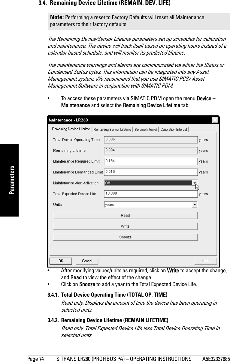
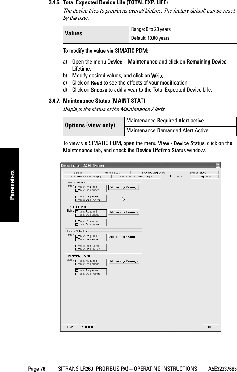

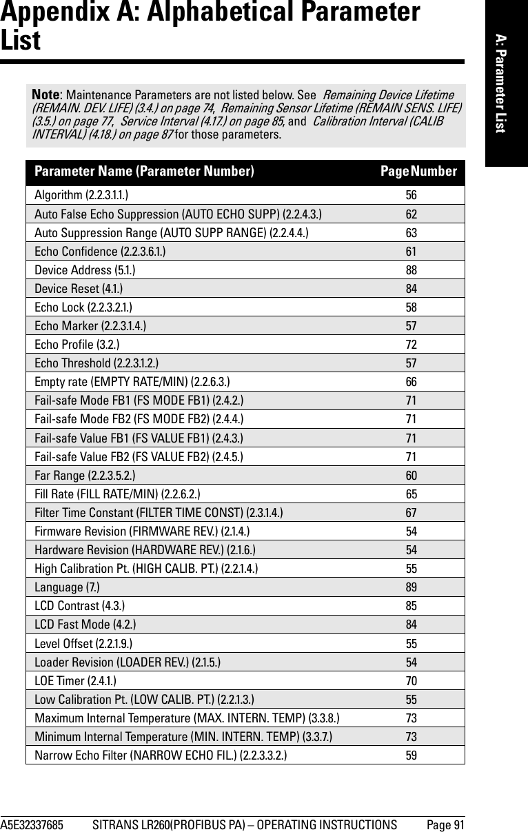
![A5E32337685 SITRANS LR260 (PROFIBUS PA) – OPERATING INSTRUCTIONS Page 85mmmmmParameters4.3. LCD ContrastThe factory setting is for optimum visibility at room temperature and in average light conditions. Extremes of temperature will lessen the contrast. Adjust the value to improve visibility in different temperatures and luminosity. Change the LCD contrast in small steps to ensure you can continue to read the display and to prevent viewing difficulties.4.4. PROFIBUS Ident Number (PROFIBUS IDENT)Identifies the device on the network. The Ident Number must match that in the GSD file (the GSD file provides information on the device to the master).4.5. Powered HoursView only. Number of hours the unit has been powered up since manufacture.To view via SIMATIC PDM, open the menu View – Wear.4.6. Power-on ResetsView only. The number of power cycles that have occurred since manufacture.To view via SIMATIC PDM, open the menu View – Wear.4.17. Service IntervalAllows for scheduling of service inspections.To access these parameters via SIMATIC PDM, open the menu Device – Maintenance and click on the Service Schedule tab.4.17.1. Time Last Serviced (TIME LAST SERV)View only. Time elapsed since device was last serviced.Can be reset to zero via the handheld programmer (after performing a service).4.17.2. Remaining Lifetime (REMAIN LIFETIME)View only. The sum of Total Service Interval less Time Last Serviced.4.17.3. Maintenance Required Limit (MAINT REQ LIMIT)If Remaining Lifetime is equal to or less than this limit, a Maintenance Required status is generated. Values Range: 0 (High contrast) to 20 (Low contrast). Default: Matches factory calibration for best visual contrast.OptionsSTD PROFILE Standard Profile (uses generic GSD for 2 AIFB [ident # = 0x9701]* MANUFACTURERManufacturer-specific (uses Siemens EDD and GSD file, which identifies the LR260 [PROFIBUS PA]) [ident # = 0x8162]STD – AIFB 1 ONL.Standard Profile AIFB 1 only (uses generic GSD for 1 AIFB) [ident # = 0x9700]Values Range: 0 to 20 yearsDefault: 0.164 years](https://usermanual.wiki/Siemens-Canada-Siemens-Milltronics-Process-Instruments/LR260.User-Manual-2/User-Guide-2338054-Page-91.png)


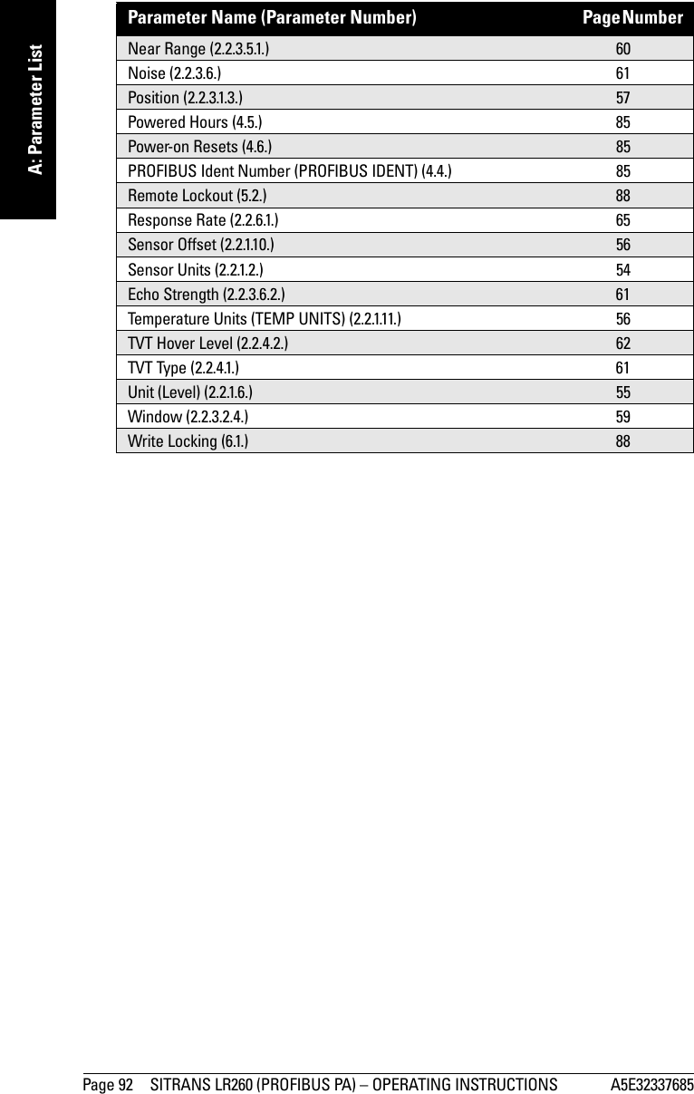


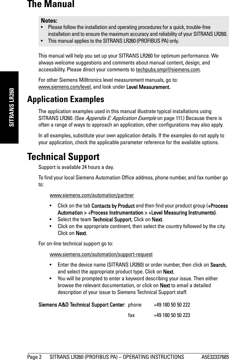
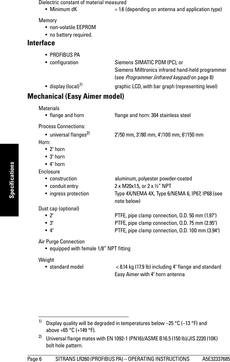
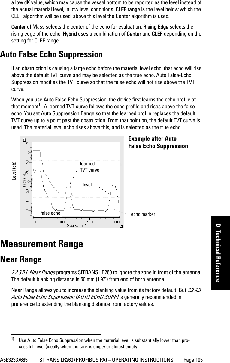
![Page 104 SITRANS LR260 (PROFIBUS PA)– OPERATING INSTRUCTIONS A5E32337685mmmmmD: Technical ReferenceHigher order mathematical techniques and algorithms are used to provide intelligent processing of microwave reflection profiles. This “knowledge based” technique produces superior performance and reliability.Time Varying Threshold (TVT) CurvesA Time Varying Threshold (TVT) curve hovers above the echo profile to screen out unwanted reflections (false echoes). In most cases the material echo is the only one which rises above the default TVT curve. In a vessel with obstructions a large false echo may rise above the default TVT. The Auto False Echo Suppression feature (see below) can be used to screen it out.The device characterizes all echoes that rise above the TVT as potential good echoes. Each peak is assigned a rating based on its strength, area, height above the TVT, amongst other characteristics. The true echo is selected based on the setting for the Echo selection algorithm [Algorithm (2.2.3.1.1.)]. Echo LockIf the echo selected by Algorithm is within the Echo Lock window, the window is centered about the echo, which is used to derive the measurement.•Echo Lock Off: SITRANS LR260 responds immediately to a new selected echo (within the restrictions set by the Maximum Fill / Empty Rate), but measurement reliability is affected.Echo Position DetectionThe echo position algorithm (2.2.3.1.3. Position) determines which point on the echo will be used to calculate the precise time of flight, and calculates the range using the calibrated propagation velocity (adjusted by a propagation factor, if necessary). The options are Center or CLEF (Constrained Leading Edge Fit), Hybrid, or Rising Edge. CLEF uses the leading edge of the echo. It can be used to compensate for materials with High Cal. Pt.= 0obstruction at 1.2 mmaterial level at 2.9 mecho markerfalse echo true echo TVT curvesensor reference pointLow Cal. Pt.](https://usermanual.wiki/Siemens-Canada-Siemens-Milltronics-Process-Instruments/LR260.User-Manual-2/User-Guide-2338054-Page-110.png)
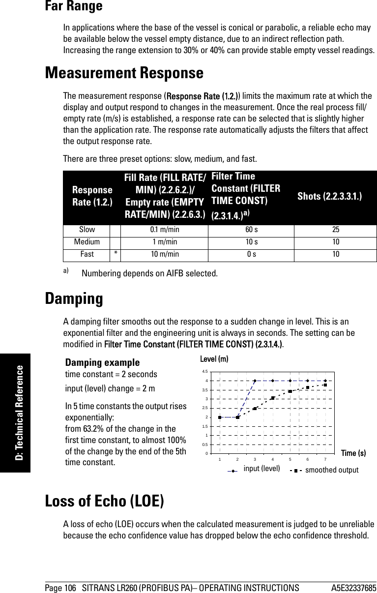

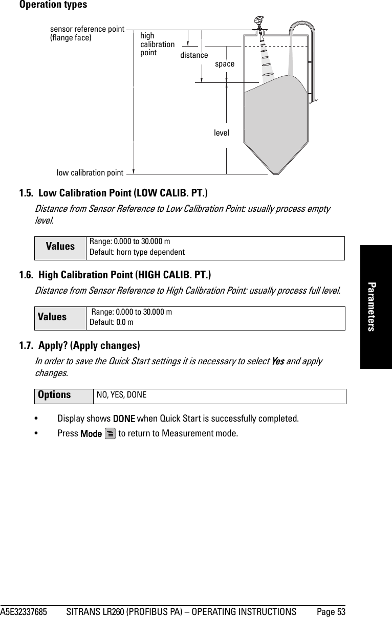
Secondary Value 2 [Distance](Sensor Units)Sensor OffsetLevel OffsetHigh Calibration PointHigh Level Point Low Calibration Point Low Level PointCalibration TypeLinearization TypePVSV1SV2AIFB2(Analog Input)](https://usermanual.wiki/Siemens-Canada-Siemens-Milltronics-Process-Instruments/LR260.User-Manual-2/User-Guide-2338054-Page-120.png)

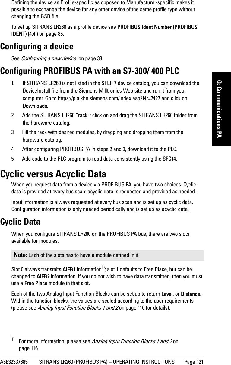
![Page 120 SITRANS LR260 (PROFIBUS PA) – OPERATING INSTRUCTIONS A5E32337685mmmmmG: Communications PAPower DemandsTo determine how many devices can be connected to a bus line, calculate the combined maximum current consumption of all the connected devices: 15 mA for SITRANS LR260. Allow a current reserve for safety. PROFIBUS addressA unique PROFIBUS address identifies each device on the network. To set the PROFIBUS address see Device Address (5.1.) on page 88.Resetting the PROFIBUS address to 126:• Via SIMATIC PDM:a) Open the menu Device – Device Reset and click on Reset Address to 126.b) Click on OK: the address will be reset to 126, and if the address lock was on, it will be disabled.• Via the handheld programmer:a) Navigate to Service (4.) > Device Reset (4.1.). (You can enter the numeric value instead of navigating via the Arrow keys.)b) Press RIGHT Arrow to open Edit Mode then scroll down to DEV ADDRESS and press RIGHT Arrow to select it. The address will be reset to 126, and if the address lock was on, it will be disabled.c) Press LEFT Arrow to exit.Operating as a Profile DeviceEvery manufactured PROFIBUS product has a unique PROFIBUS identification number which identifies it to the system. PROFIBUS Profile Standard version 3.01 also defines a Profile Model which can identify a product as a generic profile device on the network. SITRANS LR260 can be identified in one of three ways:Notes:• It is possible to change the device address via a Class 1 master (for example, a PLC) and lock the device address to prevent further changes.• If this Address Lock is on, the PA address cannot be changed. This lock can be disabled only by performing an Address Reset.Device Identification Profile ModelSTD PROFILE Standard Profile (uses generic GSD for 2 AIFB [ident # = 0x9701]* MANUFACTURER Manufacturer-specific (uses Siemens EDD and GSD file, which identifies the LR260 [PROFIBUS PA]) [ident # = 0x8162]STD – AIFB 1 ONLY Standard Profile AIFB 1 only (uses generic GSD for 1 AIFB) [ident # = 0x9700]](https://usermanual.wiki/Siemens-Canada-Siemens-Milltronics-Process-Instruments/LR260.User-Manual-2/User-Guide-2338054-Page-126.png)
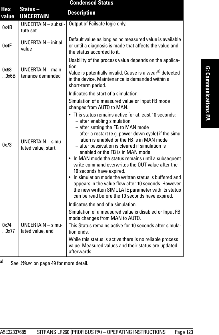
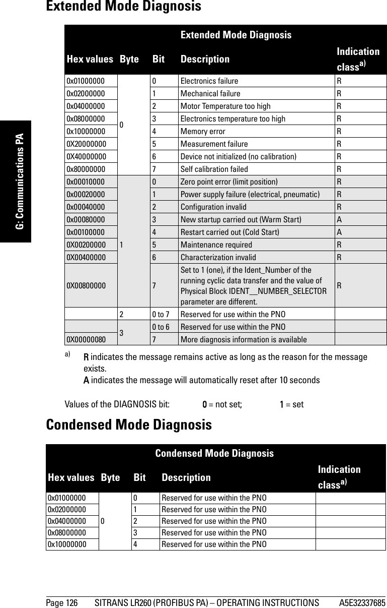
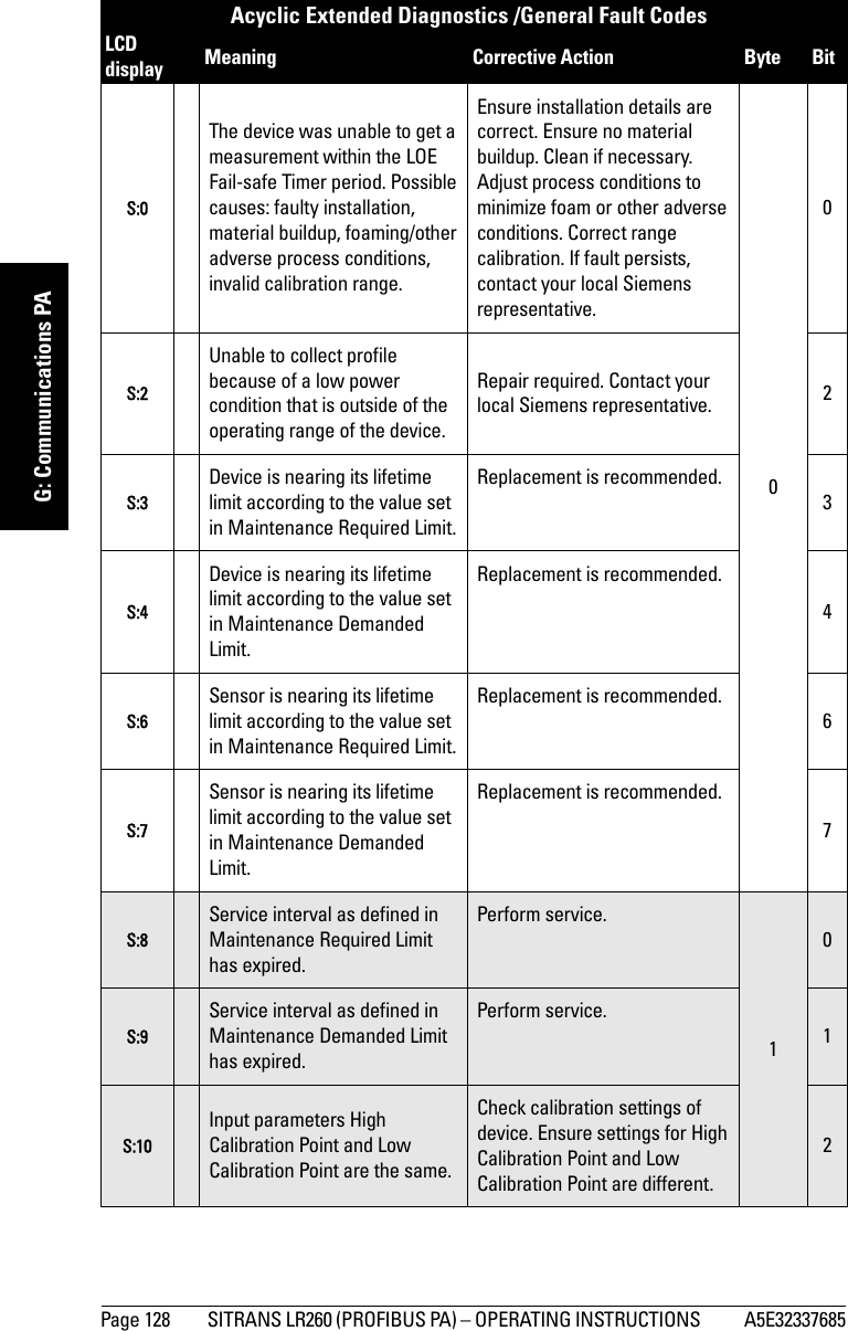
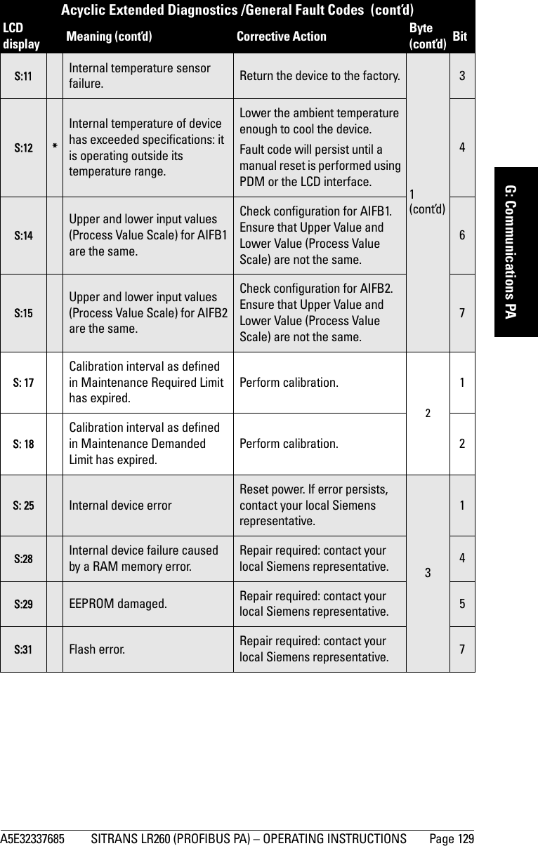
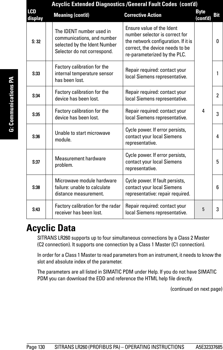
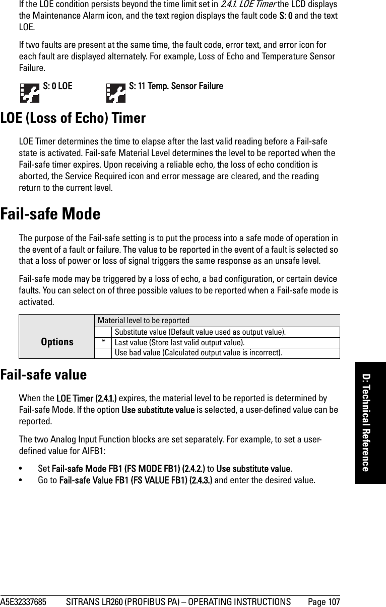
![A5E32337685 SITRANS LR260 (PROFIBUS PA) – OPERATING INSTRUCTIONS Page 127mmmmmG: Communications PAAcyclic Extended Diagnostics (General Fault Codes)In addition to the extended diagnostics available by cyclic data exchange (shown above), further extended diagnostics are available via acyclic communications. This consists of six bytes. See Acyclic Data on page 130 for information on the location of the Extended Diagnostics0x200000000 (cont’d)5 Reserved for use within the PNO0x40000000 6 Reserved for use within the PNO0x80000000 7 Reserved for use within the PNO0x0008000023New startup carried out (Warm Start) A0x00100000 4Restart carried out (Cold Start) A0x00200000 5Maintenance required R0x00400000 6Reserved for use within the PNO0x00800000 7Set to 1 (one), if the Ident_Number of the running cyclic data transfer and the value of Physical Block IDENT__NUMBER_SELECTOR parameter are different.R0x0001000030 Failure of the device or armature R0x00020000 1 Maintenance demanded R0x00040000 2 Device is in function check mode, or simulation, or under local control e.g. maintenance R0x00080000 3The process conditions do not allow the return of valid values. (Set if a value has the quality Uncertain - Process related, no maintenance or Bad - Process related, no maintenance.)R4 to 7 Reserved for use within the PNO40 to 6 Reserved for use within the PNO0x80000000 70: There is no more information available1: More diagnosis information is available in DIAGNOSIS_EXTENSIONa) R indicates the message remains active as long as the reason for the message exists.A indicates the message will automatically reset after 10 secondsNote: Certain fault codes (identified by an asterisk [*] in the table below) will persist until a manual reset has been performed (see Fault Reset (3.1.) on page 72).Condensed Mode Diagnosis (cont’d)Hex values Byte Bit Description (cont’d) Indication classa) (cont’d)](https://usermanual.wiki/Siemens-Canada-Siemens-Milltronics-Process-Instruments/LR260.User-Manual-2/User-Guide-2338054-Page-133.png)