Siemens Canada Siemens Milltronics Process Instruments LR260 SITRANS LR260 Level Probing Radar User Manual LR260 PA EN 001 AA
Siemens Canada Ltd. - Siemens Milltronics Process Instruments SITRANS LR260 Level Probing Radar LR260 PA EN 001 AA
Contents
User Manual 2
SITRANS
Radar Transmitters
SITRANS LR260 (PROFIBUS PA)
Operating Instructions 12/2013

© Siemens AG 2013
Safety Guidelines: Warning notices must be observed to ensure personal safety as well as that of
others, and to protect the product and the connected equipment. These warning notices are
accompanied by a clarification of the level of caution to be observed.
Qualified Personnel: This device/system may only be set up and operated in conjunction with this
manual. Qualified personnel are only authorized to install and operate this equipment in accordance with
established safety practices and standards.
Unit Repair and Excluded Liability:
The user is responsible for all changes and repairs made to the device by the user or the user’s
agent.
All new components are to be provided by Siemens Milltronics Process Instruments.
Restrict repair to faulty components only.
Do not reuse faulty components.
Warning: Cardboard shipping package provides limited humidity and moisture protection. This product
can only function properly and safely if it is correctly transported, stored, installed, set up, operated, and
maintained.
This product is intended for use in industrial areas. Operation of this equipment in a residential area
may cause interference to several frequency based communications.
Note: Always use product in accordance with specifications.
Copyright Siemens AG 2013. All Rights
Reserved
Disclaimer of Liability
This document is available in bound version and in
electronic version. We encourage users to purchase
authorized bound manuals, or to view electronic
versions as designed and authored by Siemens
Milltronics Process Instruments. Siemens Milltronics
Process Instruments will not be responsible for the
contents of partial or whole reproductions of either
bound or electronic versions.
While we have verified the contents of this
manual for agreement with the
instrumentation described, variations remain
possible. Thus we cannot guarantee full
agreement. The contents of this manual are
regularly reviewed and corrections are
included in subsequent editions. We welcome
all suggestions for improvement.
Technical data subject to change.
MILLTRONICS®is a registered trademark of Siemens Milltronics Process Instruments.
Contact SMPI Technical Publications European Authorized Representative
at the following address:
Technical Publications Siemens AG
Siemens AG Industry Sector
Siemens Milltronics Process Instruments 76181 Karlsruhe
1954 Technology Drive, P.O. Box 4225 Deutschland
Peterborough, Ontario, Canada, K9J 7B1
Email: techpubs.smpi@siemens.com
For a selection of Siemens Milltronics level measurement manuals, go to:
www. siemens.com/processautomation. Under Process Instrumentation, select
Level
Measurement
and then go to the manual archive listed under the product family.
For a selection of Siemens Milltronics weighing manuals, go to:
www. siemens.com/processautomation. Under Weighing Technology, select
Continuous
Weighing Systems
and then go to the manual archive listed under the product family.

i
mmmmm
Table of Contents
Table of Contents
Table of Contents .................................................................................................................i
Safety Notes .............................................................................................................................................1
Safety marking symbols ..............................................................................................................1
FCC Conformity ........................................................................................................................................1
The Manual ...............................................................................................................................................2
Application Examples ...................................................................................................................2
Technical Support ....................................................................................................................................2
Abbreviations and Identifications .............................................................................................3
SITRANS LR260 Overview .................................................................................................4
Specifications ......................................................................................................................5
Dimensions ...............................................................................................................................................9
Threaded Horn Antenna with extension ...............................................................................10
Threaded Horn dimensions ......................................................................................................11
Installation ......................................................................................................................... 13
Mounting location .................................................................................................................................14
Nozzle design ...............................................................................................................................14
Nozzle location .............................................................................................................................14
Orientation in a vessel with obstructions .............................................................................15
Easy Aimer .............................................................................................................................................16
Air Purging System (Optional) ............................................................................................................17
Universal Slotted Flange ...........................................................................................................18
Dust Cap (Optional) ...............................................................................................................................19
Wiring ..................................................................................................................................21
Power .......................................................................................................................................................21
Connecting SITRANS LR260 ...............................................................................................................21
Basic PLC configuration with PROFIBUS PA ........................................................................23
Wiring setup for hazardous area installations .............................................................................24
Instructions specific to hazardous area installations ..................................................................26
Quick Start via local operation ......................................................................................27
Activating SITRANS LR260 .................................................................................................................27
The LCD Display ...........................................................................................................................27
Handheld Programmer ...............................................................................................................29
Programming SITRANS LR260 .................................................................................................30
Quick Start Wizard via the handheld programmer .......................................................................33
Requesting an Echo Profile ................................................................................................................35
Device Address ......................................................................................................................................35
Auto False Echo Suppression ............................................................................................................35
Level application example ...................................................................................................................36
Operating via SIMATIC PDM ..........................................................................................37
Functions in SIMATIC PDM ................................................................................................................37
Features of SIMATIC PDM Rev. 6.0, SP3 (or higher) ..........................................................37
Electronic Device Description (EDD) ......................................................................................38

ii
mmmmm
Table of Cotents
Configuring a new device .........................................................................................................38
Quick Start Wizard via SIMATIC PDM .............................................................................................39
Changing parameter settings using SIMATIC PDM ...........................................................42
Parameter Reference .......................................................................................................51
Pull-down menus via SIMATIC PDM .....................................................................................51
Quick Start Wizard ................................................................................................................................52
Quick Start .................................................................................................................................. 52
Setup ............................................................................................................................................ 54
Device ................................................................................................................................ 54
Input.................................................................................................................................... 54
Output................................................................................................................................. 66
Fail-safe ............................................................................................................................. 70
Diagnostics ................................................................................................................................. 72
Fault Reset ........................................................................................................................ 72
Echo Profile....................................................................................................................... 72
Measured Values (MEAS. VALUES)........................................................................... 73
Remaining Device Lifetime (REMAIN. DEV. LIFE).................................................... 74
Remaining Sensor Lifetime (REMAIN SENS. LIFE) ................................................. 77
Condensed Status Setup (COND. STAT. SETUP) .................................................... 80
Condensed Status........................................................................................................... 81
Service......................................................................................................................................... 84
Device Reset..................................................................................................................... 84
LCD Fast Mode................................................................................................................. 84
LCD Contrast..................................................................................................................... 85
PROFIBUS Ident Number (PROFIBUS IDENT).......................................................... 85
Powered Hours................................................................................................................ 85
Power-on Resets............................................................................................................. 85
Service Interval ................................................................................................................85
Calibration Interval (CALIB INTERVAL)...................................................................... 87
Communication.......................................................................................................................... 88
Device Address ............................................................................................................... 88
Remote Lockout ............................................................................................................... 88
Security........................................................................................................................................ 88
Write Locking ................................................................................................................... 88
Language..................................................................................................................................... 89
Appendix A: Alphabetical Parameter List ....................................................................91
Appendix B: Troubleshooting .........................................................................................93
Device Status Icons ..............................................................................................................................94
General Fault Codes .............................................................................................................................95
Operation Troubleshooting .................................................................................................................99
Appendix C: Maintenance ............................................................................................ 101
Unit Repair and Excluded Liability ..................................................................................................101
Appendix D: Technical Reference ...............................................................................103
Principles of Operation ..................................................................................................................... 103
Echo Processing ................................................................................................................................. 103
Process Intelligence ................................................................................................................ 103
Time Varying Threshold (TVT) Curves ................................................................................. 104

iii
mmmmm
Table of Contents
Echo Lock ................................................................................................................................... 104
Echo Position Detection .......................................................................................................... 104
Auto False Echo Suppression ............................................................................................... 105
Measurement Range ........................................................................................................................ 105
Near Range ................................................................................................................................ 105
Far Range ................................................................................................................................... 106
Measurement Response .................................................................................................................. 106
Damping ................................................................................................................................................ 106
Loss of Echo (LOE) .............................................................................................................................. 106
LOE (Loss of Echo) Timer ........................................................................................................ 107
Fail-safe Mode .................................................................................................................................... 107
Fail-safe value ........................................................................................................................... 107
Process Pressure/Temperature derating curves ..........................................................108
Horn Antenna ............................................................................................................................ 109
Appendix E: Application Example ............................................................................... 111
Flour in steel storage vessel, level measurement .............................................................111
Appendix F: PROFIBUS PA Profile Structure ............................................................. 113
PROFIBUS Level Device Design ......................................................................................................113
Description of the blocks .........................................................................................................114
Appendix G: Communications via PROFIBUS PA ..................................................... 119
Device Configuration tool ..................................................................................................................119
SIMATIC PDM ............................................................................................................................119
Network Configuration ......................................................................................................................119
The GSD file ................................................................................................................................119
Bus Termination ...................................................................................................................................119
Power Demands ..................................................................................................................................120
PROFIBUS address .............................................................................................................................120
Operating as a Profile Device ...........................................................................................................120
Configuring a device .................................................................................................................121
Configuring PROFIBUS PA with an S7-300/ 400 PLC ........................................................121
Cyclic versus Acyclic Data ................................................................................................................121
Cyclic Data ..................................................................................................................................121
Status Byte ...........................................................................................................................................122
Condensed Status ...............................................................................................................................122
Status Byte ...........................................................................................................................................124
Diagnostics ...........................................................................................................................................125
Diagnosis reply (available cyclically) ....................................................................................125
Diagnosis Object (available cyclically or acyclically) .......................................................125
Extended Mode Diagnosis ......................................................................................................126
Condensed Mode Diagnosis ..................................................................................................126
Acyclic Extended Diagnostics (General Fault Codes) ......................................................127
Acyclic Data ..........................................................................................................................................130

iv
mmmmm
Table of Cotents
Appendix H: Firmware Revision History .................................................................... 133
Glossary ............................................................................................................................ 135
Index .................................................................................................................................. 139
LCD menu structure ....................................................................................................... 141
A5E32337685 SITRANS LR260 (PROFIBUS PA) – OPERATING INSTRUCTIONS Page 1
mmmmm
SITRANS LR260
Safety Notes
Special attention must be paid to warnings and notes highlighted from the rest of the text
by grey boxes.1)
Safety marking symbols
FCC Conformity
US Installations only: Federal Communications Commission (FCC) rules
WARNING: relates to a caution symbol on the product, and means
that failure to observe the necessary precautions can result in
death, serious injury, and/or considerable material damage.
WARNING1: means that failure to observe the necessary
precautions can result in death, serious injury, and/or considerable
material damage.
Note: means important information about the product or that part of the operating
manual.
1) This symbol is used when there is no corresponding caution symbol on the product.
In manual On
product Description
Earth (ground) Terminal
Protective Conductor Terminal
(Label on product: yellow background.) WARNING: refer
to accompanying documents (manual) for details.
WARNING: Changes or modifications not expressly approved by
Siemens Milltronics could void the user’s authority to operate the
equipment.
Notes:
• This equipment has been tested and found to comply with the limits for a Class A
digital device, pursuant to Part 15 of the FCC Rules. These limits are designed to
provide reasonable protection against harmful interference when the equipment is
operated in a commercial environment.
• This equipment generates, uses, and can radiate radio frequency energy and, if not
installed and used in accordance with the instruction manual, may cause harmful
interference to radio communications. Operation of this equipment in a residential
area is likely to cause harmful interference to radio communications, in which case
the user will be required to correct the interference at his own expense.

Page 2 SITRANS LR260 (PROFIBUS PA) – OPERATING INSTRUCTIONS A5E32337685
mmmmm
SITRANS LR260
The Manual
This manual will help you set up your SITRANS LR260 for optimum performance. We
always welcome suggestions and comments about manual content, design, and
accessibility. Please direct your comments to techpubs.smpi@siemens.com.
For other Siemens Milltronics level measurement manuals, go to:
www.siemens.com/level, and look under Level Measurement.
Application Examples
The application examples used in this manual illustrate typical installations using
SITRANS LR260. (See
Appendix E: Application Example
on page 111.) Because there is
often a range of ways to approach an application, other configurations may also apply.
In all examples, substitute your own application details. If the examples do not apply to
your application, check the applicable parameter reference for the available options.
Technical Support
Support is available 24 hours a day.
To find your local Siemens Automation Office address, phone number, and fax number go
to:
www.siemens.com/automation/partner
• Click on the tab Contacts by Product and then find your product group (+Process
Automation > +Process Instrumentation > +Level Measuring Instruments).
• Select the team Technical Suppor t . Click on Next.
• Click on the appropriate continent, then select the country followed by the city.
Click on Next.
For on-line technical support go to:
www.siemens.com/automation/support-request
• Enter the device name (SITRANS LR260) or order number, then click on Search,
and select the appropriate product type. Click on Next.
• You will be prompted to enter a keyword describing your issue. Then either
browse the relevant documentation, or click on Next to email a detailed
description of your issue to Siemens Technical Support staff.
Siemens A&D Technical Support Center: phone +49 180 50 50 222
fax +49 180 50 50 223
Notes:
• Please follow the installation and operating procedures for a quick, trouble-free
installation and to ensure the maximum accuracy and reliability of your SITRANS LR260.
• This manual applies to the SITRANS LR260 (PROFIBUS PA) only.

A5E32337685 SITRANS LR260 (PROFIBUS PA) – OPERATING INSTRUCTIONS Page 3
mmmmm
SITRANS LR260
Abbreviations and Identifications
Short
form Long Form Description Units
A/D Analog to digital
AIFB Analog Input Function Block
CE / FM /
CSA
Conformitè Europèene /
Factory Mutual / Canadian
Standards Association
safety approval
CiInternal capacitance F
D/A Digital to analog
DAC Digital Analog Converter
DCS Distributed Control System control room apparatus
dK dielectric constant
IiInput current mA
IoOutput current mA
IS Intrinsically Safe safety approval
LiInternal inductance mH
LTB Level Transducer Block
mH milliHenry 10-3 Henry
F microFarad 10-6 Farad
smicrosecond 10-6 Second
PA Process Automation
(PROFIBUS)
PED Pressure Equipment
Directive safety approval
pF pico Farads 10-12 Farad
ppm parts per million
PV Primary Valuea)
a) The output from the Level Transducer Block can be called the Primary Value (or
Secondary Value). When it becomes the input to the AIFB, it is called the
Process Variable.
measured value
SELV Safety extra low voltage
SV Secondary Valueaequivalent value
TVT Time Varying Threshold sensitivity threshold
UiInput voltage V
UoOutput voltage V
Page 4 SITRANS LR260 (PROFIBUS PA) – OPERATING INSTRUCTIONS A5E32337685
mmmmm
SITRANS LR260
SITRANS LR260 Overview
SITRANS LR260 is a 2-wire 25 GHz pulse radar level transmitter for continuous monitoring
of solids and liquids in storage vessels including extreme levels of dust and high
temperatures, to a range of 30 m (98.4 ft).
The instrument consists of an electronic component coupled to a horn antenna with an
integral Easy Aimer and flange for quick and easy positioning. A dust cover or air purging
are available as options.
SITRANS LR260 supports PROFIBUS PA communication protocol, and SIMATIC PDM
software. Signals are processed using Process Intelligence which has been field-proven
in over 1, 000,000 applications worldwide (ultrasonic and radar). This device supports
acyclic communications from both a PROFIBUS Class I and Class II master.
Programming
SITRANS LR260 is very easy to install and configure via a graphical local user interface
(LUI). You can modify the built in parameters either locally via the Siemens infrared hand-
held programmer, or from a remote location via SIMATIC PDM.
Applications
• cement powder, plastic powder/pellets, grain, flour, coal, and other applications
• solids and liquids bulk storage vessels
Approvals and Certificates
SITRANS LR260 is available with General Purpose approval, or for Hazardous areas. For
details, see
Approvals
on page 7.

A5E32337685 SITRANS LR260 (PROFIBUS PA) – OPERATING INSTRUCTIONS Page 5
mmmmm
Specifications
Specifications
Power
Bus powered Per IEC 61158-2 (PROFIBUS PA)
Current consumed 15.0 mA (General Purpose or Intrinsically Safe version)
Performance
Reference operating conditions according to IEC 60770-1
• ambient temperature +15 to +25 °C (+59 to +77 °F)
• humidity 45% to 75% relative humidity
• ambient pressure 860 to 1060 mbar g (86,000 to 106,000 N/m2 g)
Measurement Accuracy (measured in accordance with IEC 60770-1)
• Maximum measured error (including hysteresis and non-repeatability)
- 25 mm (1") from minimum detectable distance
up to 300 mm
- Remainder of range = 10 mm (0.39") or 0.1% of span
(whichever is greater)
Frequency K-band (25 GHz nominal)
Max. measurement range1)
• solids 2" horn: 10 m (32.8 ft)
3" horn: 20 m (65.6 ft)
4" horn: 30 m (98.4 ft)
• liquids 2" horn: 20 m (65.6 ft)
3" horn: 30 m (98.4 ft)
4" horn: 30 m (98.4 ft)
Min. detectable distance2) 0.05 m (1.97") from end of horn
Update time3) minimum 2 seconds, depending on Response Rate
(2.2.6.1.) and LCD Fast Mode (4.2.)
Influence of ambient temperature <0.003% / K (average over full temperature range,
referenced to maximum range)
Notes:
• Siemens Milltronics makes every attempt to ensure the accuracy of these
specifications but reserves the right to change them at any time.
1) From sensor reference point.
2) See
Dimensions
on page 9.
3) Reference conditions: Response Rate (2.2.6.1.) set to FAST and LCD Fast Mode
(4.2.) set to ON

Page 6 SITRANS LR260 (PROFIBUS PA) – OPERATING INSTRUCTIONS A5E32337685
mmmmm
Specifications
Dielectric constant of material measured
• Minimum dK = 1.6 (depending on antenna and application type)
Memory
• non-volatile EEPROM
• no battery required.
Interface
• PROFIBUS PA
• configuration Siemens SIMATIC PDM (PC), or
Siemens Milltronics infrared hand-held programmer
(see
Programmer (infrared keypad)
on page 8)
• display (local)1) graphic LCD, with bar graph (representing level)
Mechanical (Easy Aimer model)
Materials
• flange and horn flange and horn: 304 stainless steel
Process Connections:
• universal flanges2) 2"/50 mm, 3"/80 mm, 4"/100 mm, 6"/150 mm
Horn:
•2" horn
•3" horn
•4" horn
Enclosure
• construction aluminum, polyester powder-coated
• conduit entry 2 x M20x1.5, or 2 x ½” NPT
• ingress protection Type 4X/NEMA 4X, Type 6/NEMA 6, IP67, IP68 (see
note below)
Dust cap (optional)
• 2" PTFE, pipe clamp connection, O.D. 50 mm (1.97")
• 3" PTFE, pipe clamp connection, O.D. 75 mm (2.95")
• 4" PTFE, pipe clamp connection, O.D. 100 mm (3.94")
Air Purge Connection
• equipped with female 1/8” NPT fitting
Weight
• standard model < 8.14 kg (17.9 lb) including 4" flange and standard
Easy Aimer with 4" horn antenna
1) Display quality will be degraded in temperatures below –25 °C (–13 °F) and
above +65 °C (+149 °F).
2) Universal flange mates with EN 1092-1 (PN16)/ASME B16.5 (150 lb)/JIS 2220 (10K)
bolt hole pattern.

A5E32337685 SITRANS LR260 (PROFIBUS PA) – OPERATING INSTRUCTIONS Page 7
mmmmm
Specifications
Mechanical (Threaded Connection model)
• threaded connection 2" NPT (ASME B1.20.1), R (BSPT, EN 10226-1) or
G (BSPP, EN ISO 228-1)
materials 316L /1.4404 or 316L /1.4435 stainless steel
PTFE emitter
Environmental
• location indoor/ outdoor
• altitude 2000 m (6562 ft) max.
• ambient temperature 40 to +80 °C (40 to +176 °F)
• relative humidity suitable for outdoor
Type 4X/NEMA 4X, Type 6/NEMA 6, IP67 enclosure
(see note below)
• installation category I
• pollution degree 4
Process
•temperature
1) -40 to +200 °C (-40 to +392 °F)2)
(at process connection with FKM O-ring)
• pressure (vessel)1Refer to
Process Pressure/Temperature derating curves
on
page 108.
Approvals
•General CSA
US/C, FM, CE
• Radio Europe (R&TTE), FCC, Industry Canada
• Hazardous ATEX II 1GD, 1/2D, 2D Ex ia IIC T4 Ga, Ex ta IIIC T100 °C Da
ATEX II 3G Ex nA IIC T4 Gc
IECEx SIR 11.0153X Ex ia IIC T4 Ga, Ex ta IIIC T100 °C Da
FM/CSA Class I, Div. 1, Groups A, B, C, D, Class II, Div. 1,
Groups E, F, G, Class III T4
FM/CSA Class I, Div 2, Groups A, B, C, D T5
SABS ARP0108 Ex ia IIC T4 Ga
Notes:
• Check
Approvals
on page 7, for the specific configuration you are about to use or
install.
• Use appropriate conduit seals to maintain IP or NEMA rating.
1) The maximum temperature is dependent on the ambient temperature and vessel
pressure. For more detail, or for other configurations, see
Process Pressure/
Temperature derating curves
on page 108.
2) Pressure rated version for maximum process temperature of 80 °C (176 °F)
Note: The device nameplate lists the approvals that apply to your device.

Page 8 SITRANS LR260 (PROFIBUS PA) – OPERATING INSTRUCTIONS A5E32337685
mmmmm
Specifications
INMETRO: DNV 12.0081 X
Ex ia IIC T4 Ga
Ex ta IIIC T100 °C Da
-40 °C Ta +80 °C
IP67/IP68
DNV #OCP 0017
ABNT NBR IEC 60079-0:2008
ABNT NBR IEC 60079-11:2009
ABNT NBR IEC 60079-26:2008 e
ABNT NBR IEC 60079-31:2011
Programmer (infrared keypad)
Siemens Milltronics Infrared IS (Intrinsically Safe) Hand Programmer for hazardous and
all other locations (battery is non-replaceable)
• approval ATEX II 1GD, Ex ia IIC T4 Ga, Ex iaD 20 T135 °C,
SIRA 01ATEX2147
IECEx SIR 09.0073 Ex ia IIC T4 Ga, Ex iaD 20 T135 °C
FM/CSA: Class I, Div. 1, Groups A, B, C, D
INMETRO: DNV 12.0075
Ex ia IIC T4 Ga
Ex ta IIIC T135 °C Da
DNV #OCP 0017
ABNT NBR IEC 60079-0:2008
ABNT NBR IEC 60079-11:2009
ABNT NBR IEC 60079-26:2008 e IEC 61241-11:2005
• ambient temperature 20 to +50 °C (5 to +122 °F)
• interface proprietary infrared pulse signal
• power 3 V lithium battery
• weight 150 g (0.3 lb)
• color black
• Part Number 7ML5830-2AJ
A5E32337685 SITRANS LR260 (PROFIBUS PA) – OPERATING INSTRUCTIONS Page 9
mmmmm
Specifications
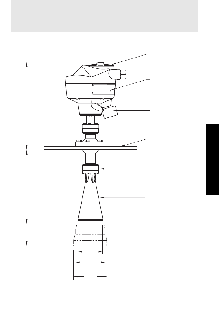
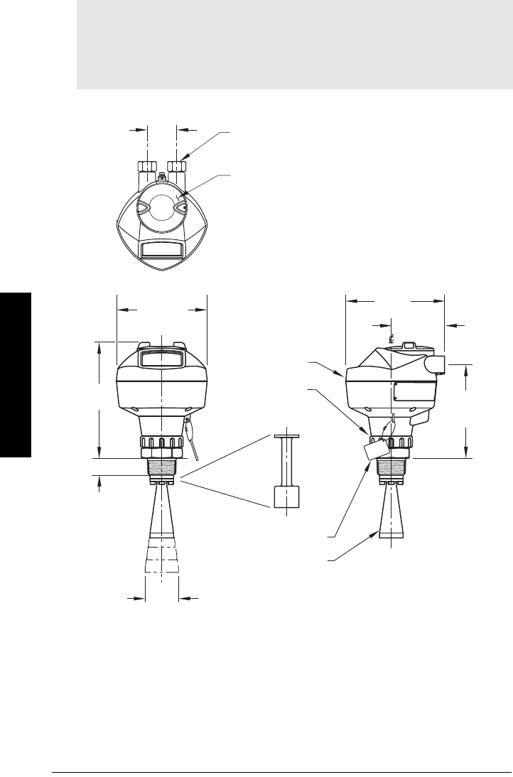
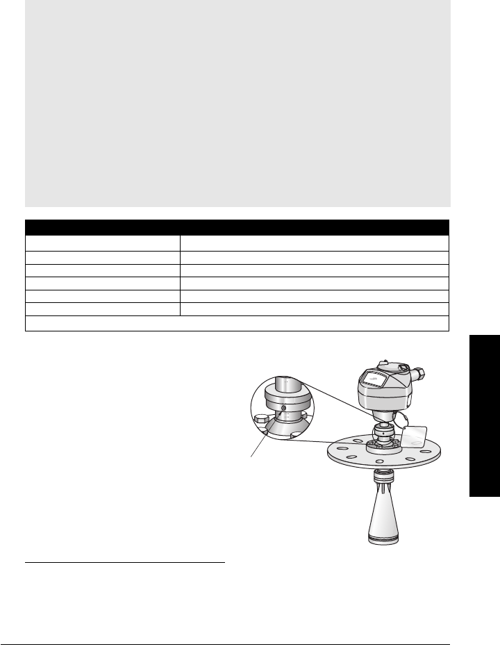
Dimensions
Notes:
• Process temperature and pressure capabilities are dependent upon information on
the process device tag.
• Signal amplitude increases with horn diameter, so use the largest practical size.
268 mm
(10.6")
2" horn: 163 mm (6.4")
3" horn: 228 mm (9.0")
4" horn: 285 mm (11.2")
sensor
reference
point
horn
universal slotted
flange
process device tag
nameplate
enclosure/electronics
4" horn
3" horn
2" horn
97.5 mm
(3.8")
74.5 mm
(2.9")
49 mm
(1.9")
optional extension
Page 10 SITRANS LR260 (PROFIBUS PA) – OPERATING INSTRUCTIONS A5E32337685
mmmmm
Specifications
Threaded Horn Antenna with extension
See table under
Threaded Horn dimensions
on page 11 for horn height to sensor
reference point.
Notes:
• Process temperature and pressure capabilities are dependent upon information on
the process connection tag.
• Signal amplitude increases with horn diameter, so use the largest practical size.
• Optional extensions can be installed below the threads.
threaded cover
enclosure/
electronics
196 mm
(7.7")
154 mm
(6.1")
167 mm
(6.6")
1/2" NPT cable entry
(or alternatively, M20 cable gland)
sensor
ref.
point
retaining
collar
90 mm
(3.5")
159 mm
(6.26")
50 mm
(2.0")
horn
28 mm (1.1")
optional
100 mm (4.0 ")
horn extension
process
connection
tag
horn
O.D.

A5E32337685 SITRANS LR260 (PROFIBUS PA) – OPERATING INSTRUCTIONS Page 11
mmmmm
Specifications
Threaded Horn dimensions
Antenna
Type Antenna O.D. Height to sensor reference pointa)
a) Height from bottom of horn to sensor reference point as shown: see
Threaded
Horn Antenna with extension
on page 10.
Beam
Angleb)
b) – 3dB in the direction of the polarization axis (see
Polarization reference point
on page 15 for an illustration).
Measurement
Range
1-1/2"
threaded
connection
2" threaded
connection
3" threaded
connection
2" Horn 47.8mm (1.88") N/A 166mm (6.55") 180mm (7.09") 15 degrees 20m (65.6 ft)
3" Horn 74.8mm (2.94") N/A 199mm (7.85") 213mm (8.39") 10 degrees 20m (65.6 ft)
4" Horn 94.8mm (3.73") N/A 254mm (10") 268mm (10.55") 8 degrees 20m (65.6 ft)

Page 12 SITRANS LR260 (PROFIBUS PA) – OPERATING INSTRUCTIONS A5E32337685
mmmmm
Specifications
Notes

A5E32337685 SITRANS LR260 (PROFIBUS PA) – OPERATING INSTRUCTIONS Page 13
mmmmm
Installation
Installation
1)
WARNINGS:
• Installation shall be performed only by qualified personnel and in
accordance with local governing regulations.
• SITRANS LR260 is to be used only in the manner outlined in this manual,
otherwise protection provided by the device may be impaired.
• Never attempt to loosen, remove, or disassemble process connection
or instrument housing while vessel contents are under pressure.
• This product is designated as a Pressure Accessory per Directive
97/23/EC and is not intended for use as a safety device.
• Materials of construction are chosen based on their chemical
compatibility (or inertness) for general purposes. For exposure to
specific environments, check with chemical compatibility charts
before installing.
• The user is responsible for the selection of bolting and gasket materials
which will fall within the limits of the flange and its intended use and
which are suitable for the service conditions.
• Improper installation may result in loss of process pressure.
Notes:
• For European Union and member countries, installation must be according to ETSI
EN 302372.
• Refer to the device nameplate for approval information.
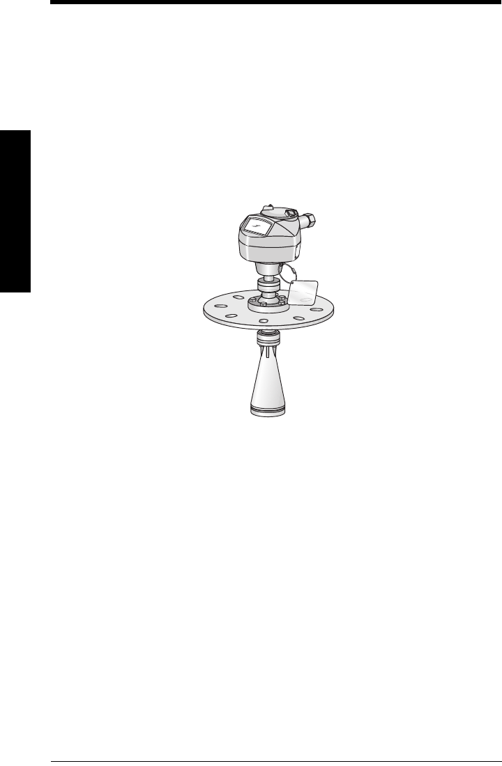
• The Process Device Tag shall remain with the process pressure boundary
assembly1. In the event the instrument package is replaced, the Process Device Tag
shall be transferred to the replacement unit.
• SITRANS LR260 units are hydrostatically tested, meeting or exceeding the
requirements of the ASME Boiler and Pressure Vessel Code and the European
Pressure Equipment Directive.
• The serial numbers stamped in each process connection body provide a unique
identification number indicating date of manufacture.
Example: MMDDYY – XXX (where MM = month, DD = day, YY = year, and
XXX= sequential unit produced)
Further markings (space permitting) indicate flange configuration, size, equivalent
pressure class, material, and material heat code.
1) The process pressure boundary assembly comprises the components that act as a
barrier against pressure loss from the process vessel: that is, the combination of
process connection body and emitter, but normally excluding the electrical enclosure.
Page 14 SITRANS LR260 (PROFIBUS PA) – OPERATING INSTRUCTIONS A5E32337685
mmmmm
Installation
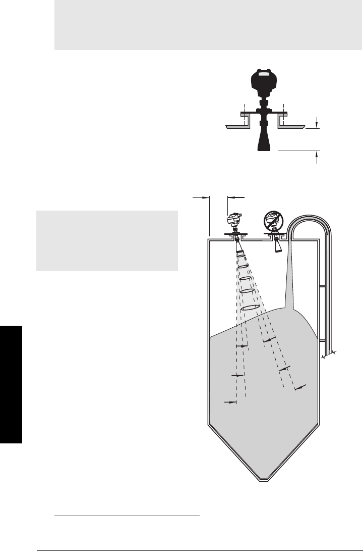
Mounting location
Nozzle design
• The end of the horn must protrude
a minimum of 10 mm (0.4”) to avoid
false echoes being reflected from
the nozzle.
• Optional antenna extensions:
100 mm (3.93"), 200 mm (70.9"),
500 mm (19.69"), 1000 mm (39.4")1)
Nozzle location
• Keep emission cone free of
interference from ladders,
pipes, I-beams or filling
streams.
• Avoid central locations on
tall, narrow vessels.
• Align the antenna so that the
radar cone is perpendicular
to the surface of the
monitored material, if
possible. (See
Easy Aimer
on page 16.)
Notes:
• Correct location is key to a successful application.
• Avoid reflective interference from vessel walls and obstructions by following the
guidelines below
1) Extensions are not recommended for applications where there may be excessive visible
vibration. Please consult the factory for more information.
Notes:
• Beam angle depends on horn size.
• For details on avoiding false
echoes, see
Auto False Echo
Suppression
on page 105.
Min. clearance:
10 mm (0.4")
beam angle:
2" horn = 15°
3" horn = 10°
4" horn = 8°
emission
cone
A5E32337685 SITRANS LR260 (PROFIBUS PA) – OPERATING INSTRUCTIONS Page 15
mmmmm
Installation
Nozzle location (continued)
• Provide easy access for viewing the display and programming via the hand
programmer.
• Provide an environment suitable to the housing rating and materials of construction.
• Provide a sunshield if the instrument will be mounted in direct sunlight.
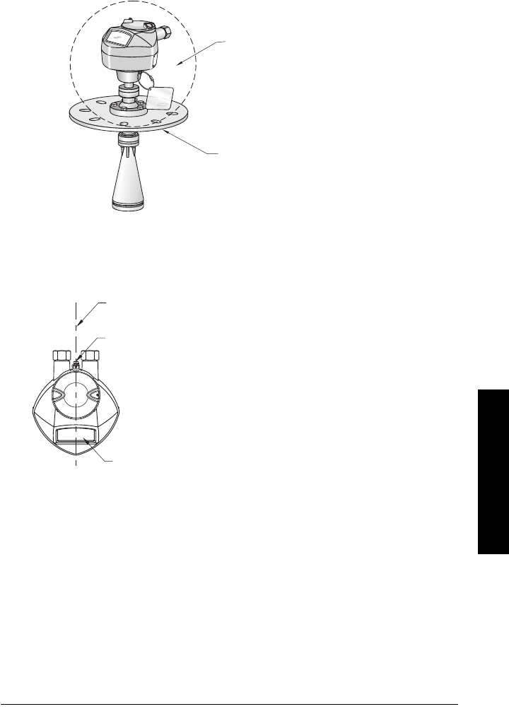
Orientation in a vessel with obstructions
Polarization reference point
ambient temperature
–40 °C to +80 °C (–40 °F to +176 °F)
process temperature (with FKM O-ring)
non-pressure version: –40 to +200 °C (–40 to +392 °F)
pressure rated version: –40 to +80 °C (–40 to +176 °F)
polarization reference
point
polarization axis
display
For best results on a vessel with
obstructions, orient the front or back of
the device toward the obstructions.
Page 16 SITRANS LR260 (PROFIBUS PA) – OPERATING INSTRUCTIONS A5E32337685
mmmmm
Installation
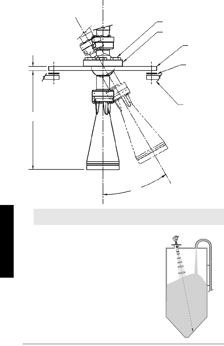
Easy Aimer
1. Holding the electronics enclosure firmly, loosen
the Easy Aimer ball locking bolts and gently
reposition the enclosure.
2. Direct SITRANS LR260 so the horn antenna is
pointed at an angle perpendicular to the
material surface, if possible. (As a guide, aim
the beam at a point approximately 2/3 of the
way across the tank diameter.)
3. When the desired position is reached, re-
tighten the 5 bolts to 15-23 Nm (11 to 17 Lbf-ft).
Note: When the Easy Aimer ball is loosened, the device is free to tilt to a maximum of
30°.
285 mm
(11.22")
0.38"
(10 mm)
Easy Aimer ball locking bolts
top clamping plate (upper socket)
bottom
clamping plate
(lower socket)
customer gasket
as required
[recommended
thickness 1.5 to
1.8 mm (0.06 to
0.07")]
customer
mounting plate, as
required
ø 4" (102 mm) min.,
central opening
30°
max.
Easy Aimer
A5E32337685 SITRANS LR260 (PROFIBUS PA) – OPERATING INSTRUCTIONS Page 17
mmmmm
Installation
Air Purging System (Optional)
For more frequent cleaning, a purging system can be installed between the flange and the
horn antenna. The system provides an 1/8” inlet (female thread) on the flange where
cooling air or cleaning fluid passes through the flange and exits the inside of the horn to
clean it. The customer will supply the purging medium by a manual or automatic valve
system.
This option is only available with the universal flange for purging shown on page 17. 1)
• The purge connection is closed
by the manufacturer, using a
1/8” plug.
• When the plug is removed to
connect a purging system, the
operator is responsible for
ensuring that the purging circuit
conforms to “Ex” requirements:
for example, by fitting an NRV
valve. 2)3)
Notes:
• The Air Purge feature should not be activated with a dust cap in place.
• Purge duration, pressure, and interval, will vary with each application. It is the user’s
responsibility to determine the requirements depending on the application and
cleaning required.
• Short duration bursts of high pressure provide more effective cleaning than
continuous low pressure air.
• Some dust particles are highly abrasive and can be drawn into the inside of the horn
during purge cleaning, damaging the internal PTFE emitter of the antenna. A
replacement kit is available from your local Siemens Milltronics representative.
• It is the customer’s responsibility to ensure that any vacuum or pressure in the
measured vessel is maintained, considering the hole that passes through the
process connection and SITRANS LR260 antenna system.
Air Consumption (Flow rate versus applied pressure)
Air Pressure (psi)2Approx. inlet volume flow rate
20 5 SCFM
40 6 SCFM
60 8 SCFM
80 9 SCFM
90 10 SCFM
Recommended 90 to 110 psi for effective cleaning with inlet flow of 10 SCFM1)
1) SCFM (standard cubic feet/minute) referenced to 14.7 psia, +68 °F and 36% relative humidity
(RH).
2) Air pressure in vessel can affect purge operation.
3) Not for pressure applications
purged process
connection with factory-
installed 1/8” NPT plug
Page 18 SITRANS LR260 (PROFIBUS PA) – OPERATING INSTRUCTIONS A5E32337685
mmmmm
Installation
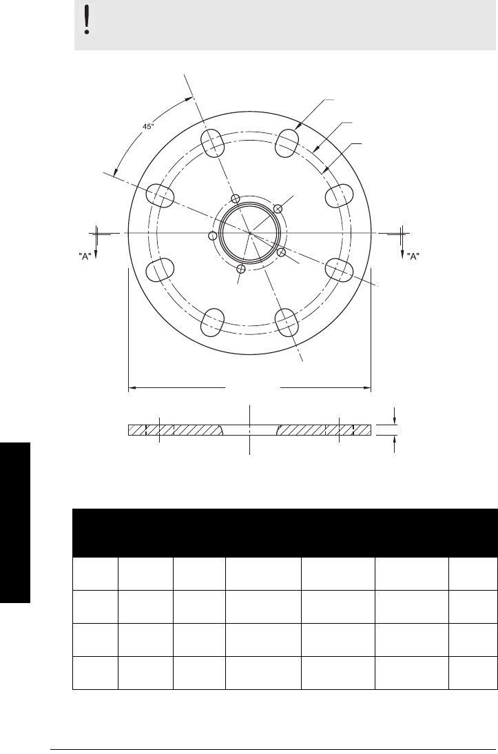
Universal Slotted Flange
Slotted Flange Dimensions (see above)1)
WARNING: The user is responsible for the selection of bolting and
gasket materials which will fall within the limits of the flange and its
intended use and which are suitable for the service conditions.
Pipe
Size
Flange
O.D.
Thick-
ness (s)
Bolt Hole
Circle Max Ø
Bolt Hole
Circle Min Ø
Bolt Hole
radius
No. of
Slotted
Holes
2" or
50 mm
6.50"
(165 mm)
0.38"
(9.65 mm)
4.92"
(125 mm)
4.72"
(120 mm)
0.38"
(9.65 mm)
4
3" or
80 mm
7.87"
(200 mm)
0.38"
(9.65 mm)
6.30"
(160 mm)
5.91"
(150 mm)
0.38"
(9.65 mm)
8
4" or
100 mm
9.00"
(229 mm)
0.38"
(9.65 mm)
7.52"
(191 mm)
6.89"
(175 mm)
0.38"
(9.65 mm)
8
6" or
150 mm
11.22"
(285 mm)
0.38"
(9.65 mm)
9.53"
(242 mm)
9.45"
(240 mm)
0.45"
(11.5 mm)
8
flange O.D.
bolt hole circle
min. diameter
number of slotted bolt holes
section A-A
thickness
bolt hole circle max. diameter
A5E32337685 SITRANS LR260 (PROFIBUS PA) – OPERATING INSTRUCTIONS Page 19
mmmmm
Installation
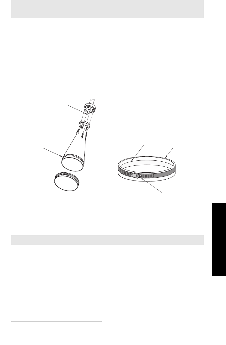
Dust Cap (Optional)
The dust cap fits onto the end of the horn and prevents the buildup of dust and other
process material inside the horn.
• It is particularly useful for applications in areas of high humidity, or with bulk solids
with a high moisture content.
• Three sizes are available, to fit the standard 2", 3", and 4" horns.
Installation
1. Thoroughly clean inside the horn. If you remove the horn for easier cleaning, take
care not to damage or bend the plastic emitter.
2. Press the cap firmly onto the horn until the ridge inside the cap snaps into position in
the groove on the outside of the horn.
3. Hand tighten the adjustable clamp supplied to secure the cap.
4. Use a screwdriver or nut driver to tighten the clamp screw until the clamp provides
an air-tight seal.
1) Universal flange mates with EN 1092-1 (PN16)/ASME B16.5 (150 lb)/JIS 2220 (10K) bolt hole
pattern.
Note: The dust cap must be removed before using the Air Purge feature. (See
Air
Purging System (Optional)
on page 17).
Note: It is critical to ensure no moisture can be trapped inside.
plastic emitter
groove ridge dust cap
clamp screw

Page 20 SITRANS LR260 (PROFIBUS PA) – OPERATING INSTRUCTIONS A5E32337685
mmmmm
Installation
Notes
A5E32337685 SITRANS LR260 (PROFIBUS PA) – OPERATING INSTRUCTIONS Page 21
mmmmm
Wiring
Wiring
Power
Connecting SITRANS LR260
1)
WARNINGS:
The DC input terminals shall be supplied from a source providing
electrical isolation between the input and output, in order to
meet the applicable safety requirements of IEC 61010-1.
All field wiring must have insulation suitable for rated voltages.
WARNINGS:
• Check the nameplate on your instrument, to verify the approval rating.
• Use appropriate conduit seals to maintain IP or NEMA rating.
Notes:
• Use twisted pair cable: AWG 22 to 14 (0.34 mm2 to 2.5 mm2).
• Separate cables and conduits may be required to conform to standard
instrumentation wiring practices or electrical codes.
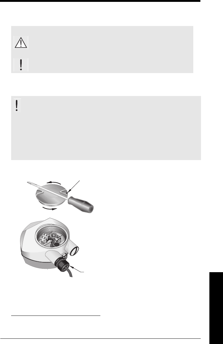
1) Depending on the approval rating, glands and plugs may be supplied with your
instrument.
Use a 2 mm Allen key to loosen the lid-lock set screw.
Unscrew the cover for access to the terminals. Use a
screwdriver for added leverage, if necessary.
cable gland1
(or 2 x 1/2" NPT metallic cable entry)

Page 22 SITRANS LR260 (PROFIBUS PA) – OPERATING INSTRUCTIONS A5E32337685
mmmmm
Wiring
1. Strip the cable jacket for approximately 70 mm (2.75") from the end of the PROFIBUS
PA cable, and thread the wires through the gland1).
2. Connect the wires to the terminals as shown below (SITRANS LR260 is not polarity
sensitive).
3. Ground the instrument according to local regulations. 2)
4. Tighten the gland to form a good seal.
5. Close the lid and secure the locking ring before programming and calibration.
1) If cable is routed through conduit, use only approved suitable-size hubs for
waterproof applications.
2) The instrument shield connection is internally connected to the external ground
lug.
Notes:
• PROFIBUS PA must be terminated at both extreme ends of the cable for it to work
properly.
• Please refer to the
PROFIBUS PA User and Installation Guidelines
(order
number 2.092), available from www.profibus.com, for information on installing
PROFIBUS devices.
instrument shield connection2
cable shield
external ground lug
A5E32337685 SITRANS LR260 (PROFIBUS PA) – OPERATING INSTRUCTIONS Page 23
mmmmm
Wiring
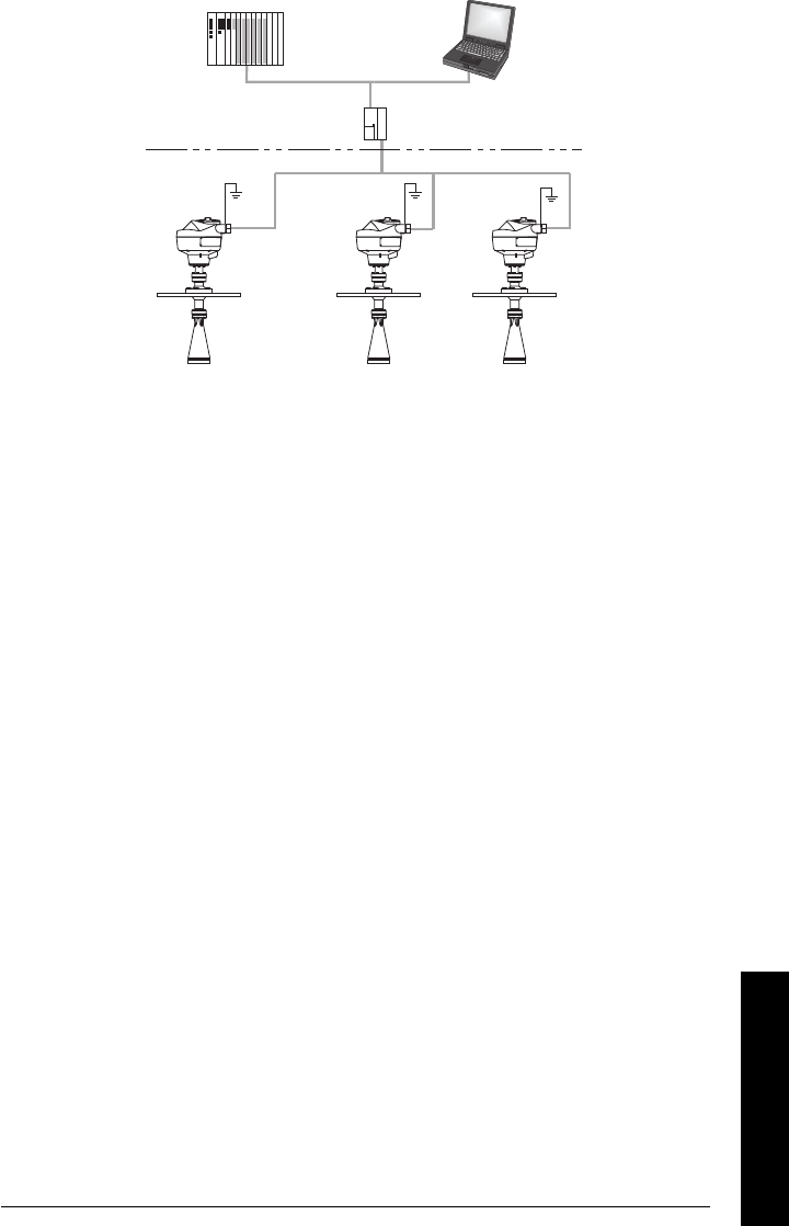
Basic PLC configuration with PROFIBUS PA
PROFIBUS PA
PROFIBUS DP
DP/PA
coupler
active PLC
PC/laptop
PDM
SITRANS LR260
(PROFIBUS PA) SITRANS LR260
(PROFIBUS PA)
SITRANS LR260
(PROFIBUS PA)
Page 24 SITRANS LR260 (PROFIBUS PA) – OPERATING INSTRUCTIONS A5E32337685
mmmmm
Wiring
Wiring setup for hazardous area installations
1. Intrinsically Safe wiring
• For wiring requirements: follow local regulations.
• Approved dust-tight and water-tight conduit seals are required for outdoor
NEMA 4X / type 4X / NEMA 6, IP67, IP68 locations.
• Refer to
Instructions specific to hazardous area installations
on page 26.
Note: Selecting a suitable PLC input module, power supply, or barrier requires
knowledge about Intrinsic Safety and the application. It is the responsibility of the
installer to ensure that the intrinsically safe installation complies with both the
apparatus approval requirements and the relevant national code of practice.
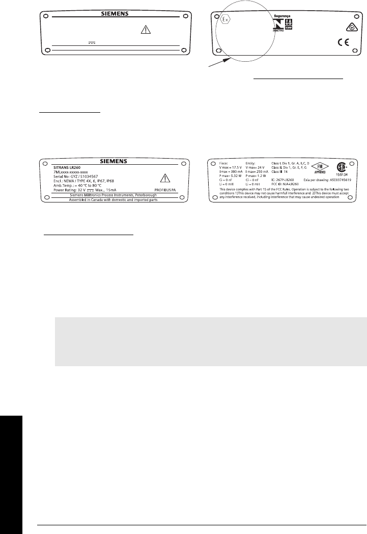
SITRANS LR260
Siemens Milltronics Process Instruments, Peterborough
7MLxxxx-xxxxx-xxxx
Encl.: NEMA / TYPE 4X, 6, IP67, IP68
Amb.Temp.: – 40°C to 80°C
Power Rating: 30 V Max., 15 mA
Serial No: GYZ / A1034567
FISCO:
Field Device
Ui = 17.5 V
Ii = 380 mA
Pi = 5.32 W
Ci = 0
Li = 0
Entity:
Ui=24V
Ii = 250 mA
Pi = 1.2 W
Ci = 0
Li = 0 0518
0891
Assembled in Canada with domestic and imported parts
PROFIBUS PA
KCC-REM-S49
SITRANSLR
II1GD,1/2D,2D
Ex ia IIC T4 Ga
Ex ta IIIC T100°C Da
SIRA 11ATEX2348X
IECEx SIR 11.0153X
ARP0108 Ex ia IIC T4 Ga
ATENÇÃO - RISCO POTENCIAL DE CARGA ELETROSTÁTICA – VEJA INSTRUÇÕES
- UTILIZAR CABOS ADEQUADOS PARA TEMPERATURAS >100 °C
WARNING: Use Cable Rated >100°C
Ex ia IIC T4 Ga
Ex ta IIIC T100°C Da
DNV 12.0081 X
OCP 0017
The ATEX certificate listed on the nameplate
can be downloaded from the product page of our website at: www.siemens.com/LR260. Go
to Support > Approvals / Certificates.
The IECEx certificate listed on the nameplate can be viewed on the IECEx website. Go to:
http://iecex.iec.ch and click on Ex Equipment Certificates of Conformity then enter the
certificate number IECEx SIR 11.0153X.
Device nameplate (ATEX/IECEX/INMETRO/C-TICK)
FM/CSA Intrinsically Safe connection drawing
number A5E03745619 can be downloaded from the product page of our website at:
www.siemens.com/LR260. Go to Support > Installation Drawings > Level Measurement >
Continuous - Radar.
Device nameplate (FM/CSA)
A5E32337685 SITRANS LR260 (PROFIBUS PA) – OPERATING INSTRUCTIONS Page 25
mmmmm
Wiring
2. Non-Sparking wiring
• For wiring requirements: follow local regulations.
• Approved dust-tight and water-tight conduit seals are required for outdoor
Type 4X/NEMA 4X, Type 6/NEMA 6, IP67 locations.
• Refer to
Instructions specific to hazardous area installations
on page 26.
3. Non-incendive wiring (US/Canada only)
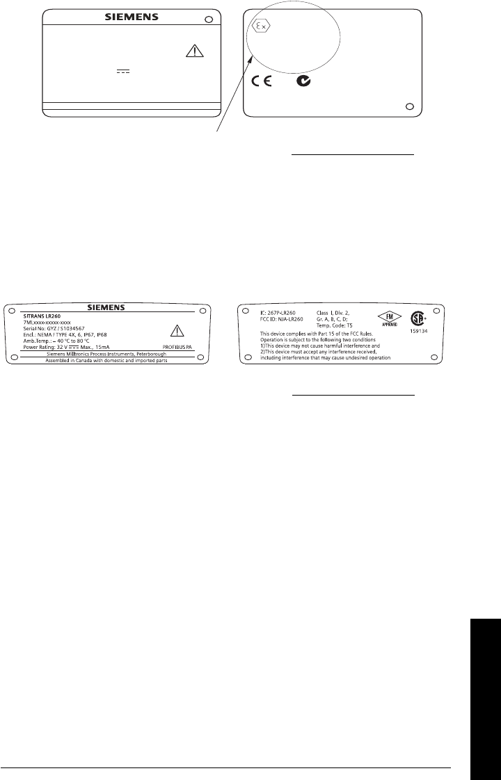
Assembled in Canada with domestic and imported parts
Siemens Milltronics Process Instruments, Peterborough
PROFIBUS PA
WARNING: Use Cable Rated > 100°C
3G
Ex nA IIC T4 Gc
SIRA 09ATEX4156X
II
SITRANS LR260
7MLxxxx-xxxxx-xxxx
Serial No.: GYZ / B1034567
Encl.: NEMA / TYPE 4X, 6, IP67, IP68
Amb. Temp.: – 40°C to 80°C
Power Rating: 30 V Max., 15 mA
0891
KCC-REM-S49
SITRANSLR
The ATEX certificate listed on the nameplate
can be downloaded from the product page of our website at: www.siemens.com/LR260. Go to
Support > Approvals / Certificates.
FM/CSA Class 1, Div 2 connection drawing number A5E03745541
can be downloaded from the product page of our website at: www.siemens.com/LR260. Go to
Support > Installation Drawings > Level Measurement > Continuous - Radar.

Page 26 SITRANS LR260 (PROFIBUS PA) – OPERATING INSTRUCTIONS A5E32337685
mmmmm
Wiring
Instructions specific to hazardous area installations
(Reference European ATEX Directive 94/9/EC, Annex II, 1/0/6)
The following instructions apply to equipment covered by certificate number
SIRA 11ATEX2348X, and SIRA 09ATEX4156X.
1) For use and assembly, refer to the main instructions.
2) The equipment is certified for use as Category 1GD, 1/2D, 2D equipment per
SIRA 11ATEX2348X and Category 3G equipment per SIRA 09ATEX4156X.
3) The equipment may be used with flammable gases and vapors with apparatus group
IIC, IIB and IIA and temperature classes T1, T2, T3 and T4.
4) The equipment has a degree of ingress protection of IP67 and a temperature class
of T100C and may be used with flammable dusts.
5) The equipment is certified for use in an ambient temperature range of –40 C to
80 C.
6) The equipment has not been assessed as a safety related device (as referred to by
Directive 94/9/EC Annex II, clause 1.5).
7) Installation and inspection of this equipment shall be carried out by suitably trained
personnel in accordance with the applicable code of practice (EN 60079-14 and
EN 60079-17 in Europe).
8) The equipment is non-repairable.
9) The certificate numbers have an ‘X’ suffix, which indicates that special conditions
for safe use apply. Those installing or inspecting this equipment must have access
to the certificates.
10) If the equipment is likely to come into contact with aggressive substances, then it is
the responsibility of the user to take suitable precautions that prevent it from being
adversely affected, thus ensuring that the type of protection is not compromised.
- Aggressive substances: for example, acidic liquids or gases that may attack
metals, or solvents that may affect polymeric materials.
- Suitable precautions: for example, establishing from the material’s data sheet
that it is resistant to specific chemicals.
SPECIAL CONDITIONS FOR SAFE USE
The 'X' suffix to the certificate number relates to the following special condition(s) for
safe use:
• Unused cable entries shall be fitted with blanking elements that can only be
removed with the aid of a tool.
• Any glands, conduit entry devices or blanking elements fitted to the equipment
shall be suitable for use in the presence of combustible dusts and certified as
such by a notified body; the installation of these devices shall not compromise
the IP6X rating of the equipment enclosure.
• For applications that use the purge facility, the user shall provide a means to
ensure that combustible dust from the hazardous area cannot enter the purge
supply in such a way as to compromise the area classification.
A5E32337685 SITRANS LR260 (PROFIBUS PA) – OPERATING INSTRUCTIONS Page 27
mmmmm
Quick Start: local
Quick Start via local operation
SITRANS LR260 carries out its level measurement tasks according to settings made via
parameters. The settings can be modified locally via the Local User Interface (LUI) which
consists of an LCD display and a handheld programmer.
A Quick Start Wizard provides an easy step-by-step guide to help you configure the
device for a simple application. There are two ways to access the wizard:
•7-step
Quick Start Wizard via the handheld programmer
on page 33
•4-step
Quick Start Wizard via SIMATIC PDM
on page 39
For more complex setups, see
Appendix E: Application Example
on page 111, and for the
complete range of parameters see
Parameter Reference
on page 51.
Activating SITRANS LR260
Power up the instrument. SITRANS LR260 automatically starts up in Measurement mode.
Press Mode to toggle between Measurement and Program Mode.1)
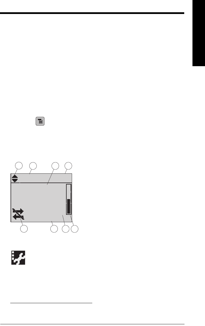
The LCD Display
Measurement mode
Normal operation
Fault present
1) In response to a key press request. For details, see
Key functions in Measurement
mode
on page 29.
M
[]
AIFB 1
21.40 °C
NO DATA EXCH.
18.91
1 – toggle indicator for AIFB 1 or AIFB 2
2 – identifies which AIFB is source of displayed
value
3 – measured value (level, space, or distance)
4 – units
5 – bar graph indicates level
6 – secondary region indicates on request1
electronics temperature, echo confidence, or
distance
7 – text area displays status messages
8 – device status indicator
678
1342
5
S: 0 LOE
7 – text area displays a fault code and an error message
8 – service required icon appears
Page 28 SITRANS LR260 (PROFIBUS PA) – OPERATING INSTRUCTIONS A5E32337685
mmmmm
Quick Start: local
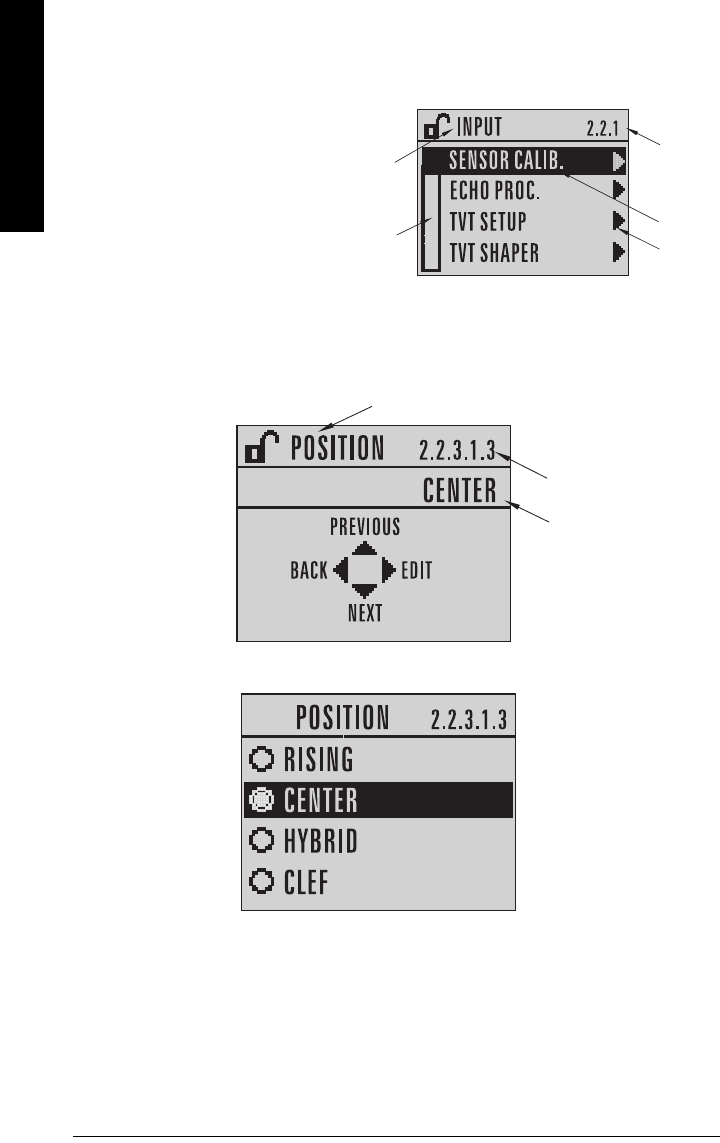
PROGRAM mode display
Navigation view
Parameter view
Edit view
current
item
number
pointer
current
item
current
menu
menu bar
• A visible menu bar indicates the
menu list is too long to display all
items.
• A band halfway down the menu
bar indicates the current item is
halfway down the list.
• The depth and relative position of
the item band on the menu bar
indicates the length of the menu
list, and approximate position of
the current item in the list.
• A deeper band indicates fewer
items.
parameter
value/selection
parameter
number
parameter name
A5E32337685 SITRANS LR260 (PROFIBUS PA) – OPERATING INSTRUCTIONS Page 29
mmmmm
Quick Start: local
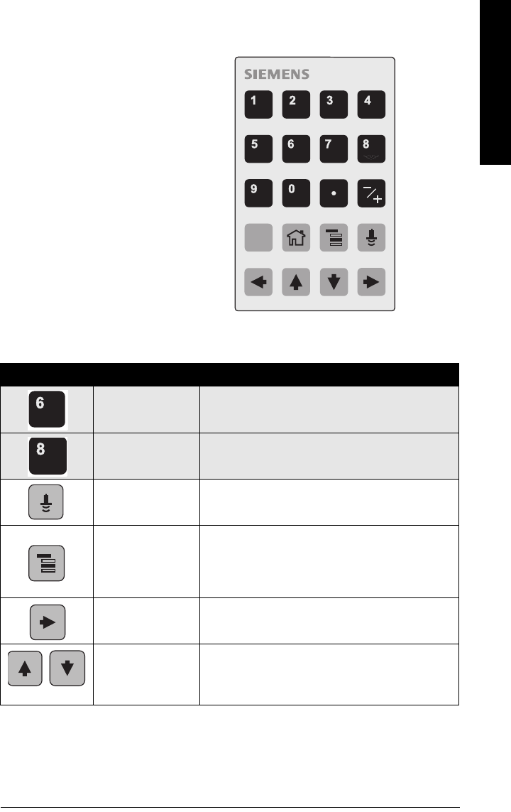
Handheld Programmer
(Part No. 7ML5830-2AJ
Key functions in Measurement mode
Key Function Result
Updates internal
enclosure temperature
reading.
New value is displayed in LCD secondary region.
Updates echo confi-
dence value. New value is displayed in LCD secondary region.
Updates distance
measurement. New value is displayed in LCD secondary region.
Mode opens PRO-
GRAM mode.
Opens the menu level last displayed in this power cycle,
unless power has been cycled since exiting PROGRAM
mode or more than 30 minutes have elapsed since PRO-
GRAM mode was used. Then top level menu will be dis-
played.
RIGHT arrow
opens PROGRAM
mode.
Opens the top level menu.
UP or DOWN arrow
toggles between
AIFB 1 and AIFB 2.
LCD displays measured value in configured Analog Input
Function Block outputs.
C
The programmer is ordered separately.
Page 30 SITRANS LR260 (PROFIBUS PA) – OPERATING INSTRUCTIONS A5E32337685
mmmmm
Quick Start: local
Programming SITRANS LR260
Change parameter settings and set operating conditions to suit your specific application.
•See
Operating via SIMATIC PDM
on page 37 for remote operation.
Programming via the handheld programmer
Parameter menus
Parameters are identified by name and organized into function groups, then arranged in a
5-level menu structure (see
LCD menu structure
on page 141).
• For the complete list of parameters with instructions, see
Parameter Reference
on page 51.
1. Enter PROGRAM mode
• Point the programmer at the display (from a
maximum distance of 500 mm [1.64 ft]).
•RIGHT arrow activates PROGRAM
mode and opens menu level 1.
•Mode opens the menu level last
displayed in PROGRAM mode within the last
30 minutes, or menu level 1 if power has been
cycled since then.
Note: While the device is in PROGRAM mode the output remains active and continues
to respond to changes in the device.
Notes:
• The Quick Start wizard settings are inter-related and changes apply only after you
click on Apply at the end of the Quick Start steps.
• Do not use the Quick Start wizard to modify individual parameter: see
instead
Parameter Reference
on page 51.
• SITRANS LR260 automatically returns to Measurement mode after a period of
inactivity in PROGRAM mode (between 15 seconds and 10 minutes, depending on
the menu level).
1. QUICK START
2. SETUP
2.1. DEVICE
2.2. INPUT
2.2.1. SENSOR CALIB.
2.2.8. ECHO PROC.
Note:
In Navigation mode,
ARROW keys move to the
next menu item in the
direction of the arrow.
display
handheld programmer
Max. 500 mm
(1.64 ft)
A5E32337685 SITRANS LR260 (PROFIBUS PA) – OPERATING INSTRUCTIONS Page 31
mmmmm
Quick Start: local
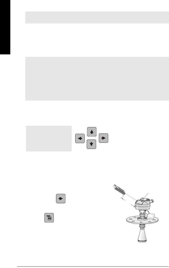
2. Navigating: key functions in Navigation mode
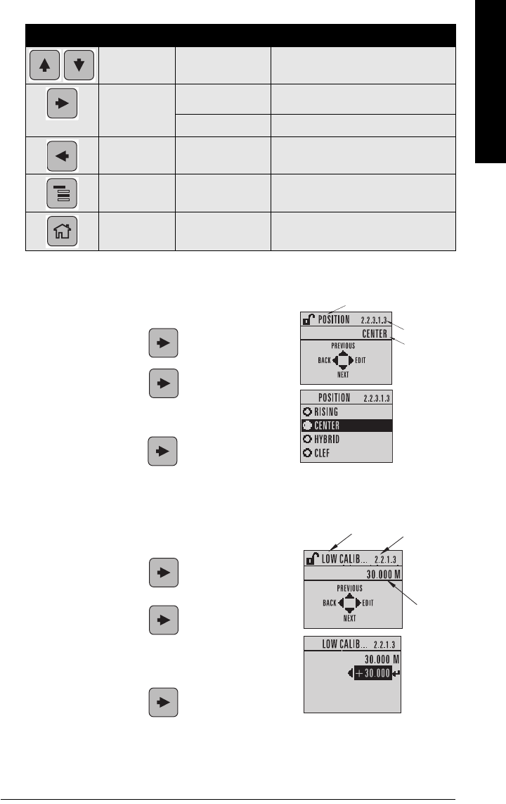
3. Editing in PROGRAM mode
Selecting a listed option
a) Navigate to the desired parameter.
b) Press RIGHT arrow to open parameter
view.
c) Press RIGHT arrow again to open Edit
mode. The current selection is highlighted.
Scroll to a new selection.
d) Press RIGHT arrow to accept it
The LCD returns to parameter view and displays
the new selection.
Changing a numeric value
a) Navigate to the desired parameter.
b) Press RIGHT arrow to open parameter
view. The current value is displayed.
c) Press RIGHT arrow again to open Edit
mode. The current value is highlighted.
d) Key in a new value.
e) Press RIGHT arrow to accept it. The LCD
returns to parameter view and displays the new
selection.
Key Name Menu level Function
UP or DOWN
arrow menu or parameter Scroll to previous or next menu or param-
eter.
RIGHT arrow menu Go to first parameter in the selected
menu, or open next menu.
parameter Open Edit mode.
LEFT arrow menu or parameter Open parent menu.
Mode menu or parameter Change to MEASUREMENT mode.
Home menu or parameter Open top level menu: menu 1.
parameter name
current
value
parameter
number
parameter
number
parameter name
current
selection
Page 32 SITRANS LR260 (PROFIBUS PA) – OPERATING INSTRUCTIONS A5E32337685
mmmmm
Quick Start: local
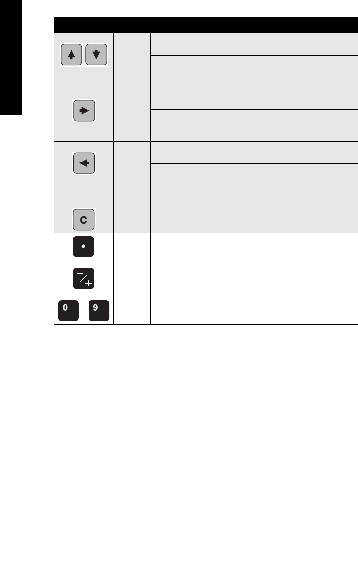
Key functions in Edit mode
Key Name Function
UP or
DOWN
arrow
Selecting
options Scrolls to item.
Alpha-
numeric
editing
- Increments or decrements digits
- Toggles plus and minus sign
RIGHT
arrow
Selecting
options
- Accepts the data (writes the parameter)
- Changes from Edit to Navigation mode
Numeric
editing
- Moves cursor one space to the right
- or with cursor on Enter sign, accepts the data and
changes from Edit to Navigation mode
LEFT
arrow
Selecting
options Cancels Edit mode without changing the parameter
Numeric
editing
- Moves cursor to plus/minus sign if this is the first
key pressed
- or moves cursor one space to the left.
- or with cursor on Cancel arrow, cancels the entry
Clear Numeric
editing Erases the display.
Decimal
point
Numeric
editing Enters a decimal point.
Plus or
minus
sign
Numeric
editing Changes the sign of the entered value.
to Numeral Numeric
editing Enters the corresponding character.
A5E32337685 SITRANS LR260 (PROFIBUS PA) – OPERATING INSTRUCTIONS Page 33
mmmmm
Quick Start: local
Quick Start Wizard via the handheld programmer
1. Quick Start
a. Point the programmer at the display (from a maximum distance of 500 mm [1.64 ft]),
then press RIGHT arrow to activate PROGRAM mode and open menu level 1.
b. Press RIGHT arrow twice to navigate to menu item 1.1 and open parameter
view.
c. Press RIGHT arrow to open Edit mode or DOWN arrow to accept default
values and move directly to the next item.
d. To change a setting, scroll to the desired item or key in a new value.
e. After modifying a value, press RIGHT arrow to accept it and press DOWN arrow
to move to the next item.
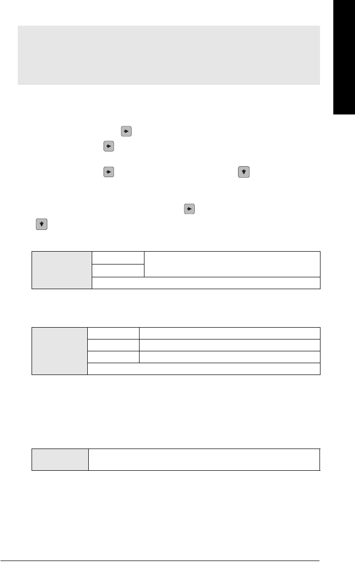
1.1. Application Type
1.2. Response Rate
Sets the reaction speed of the device to measurement changes in the target range.
Use a setting just faster than the maximum filling or emptying rate (whichever is
greater).
1.3. Units
Select the units for the Quick Start variables (high and low calibration point, and level,
distance, or space)
Notes:
• The Quick Start Wizard is a complete package and the settings are inter-related.
• Do not use the Quick Start wizard to modify individual parameters: see instead
Parameter Reference
on page 51 (perform customization for your application after
the quick start has been completed).
Options
STEEL Silo construction
CONCRETE
Default: STEEL
Options
SLOW 0.1 m/minute
MED 1.0 m/minute
FAST 10.0 m/minute
Default: FAST
Options M, CM, MM, FT, IN
Default: M
Page 34 SITRANS LR260 (PROFIBUS PA) – OPERATING INSTRUCTIONS A5E32337685
mmmmm
Quick Start: local
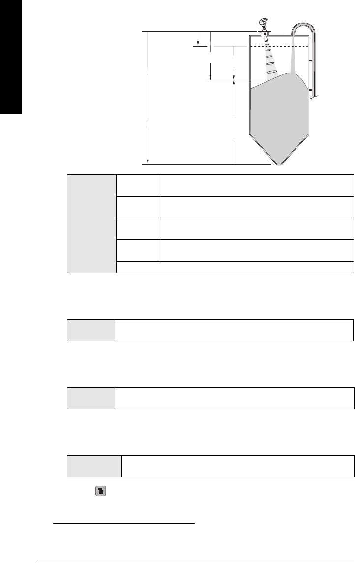
1.4. Operation
1)
1.5. Low Calibration Point
Distance from Sensor Reference to Low Calibration Point: usually process empty
level. (See 1.4. Operation for an illustration.)
1.6. High Calibration Point
Distance from Sensor Reference to High Calibration Point: usually process full level.
(See 1.4. Operation for an illustration.)
1.7. Apply? (Apply changes)
In order to save the Quick Start settings it is necessary to select Yes to apply
changes.
Press Mode to return to Measurement mode. SITRANS LR260 is now ready to operate.
Operation
types
NO
SERVICE
SITRANS LR260 stops updating measurements. Last valid
measurement is displayed.
LEVEL Distance to material surface referenced from Low Calibration
Point (process empty level).
SPACE Distance to material surface referenced from High Calibration
Point (process full level).
DISTANCE Distance to material surface referenced from Sensor Refer-
ence Point.
Default: DISTANCE
1) The point from which High and Low Calibration points are referenced: see
Dimensions
on page 9.
Values Range: 0.0000 to 30.000 m
Default: horn type dependent
Values Range: 0.0000 to 30.000 m
Default: 0.0 m
Options YES, NO, DONE
(Display shows DONE when Quick Start is successfully completed)
high
calibration
point
low calibration point
level
space
distance
sensor reference point
(flange face)
A5E32337685 SITRANS LR260 (PROFIBUS PA) – OPERATING INSTRUCTIONS Page 35
mmmmm
Quick Start: local
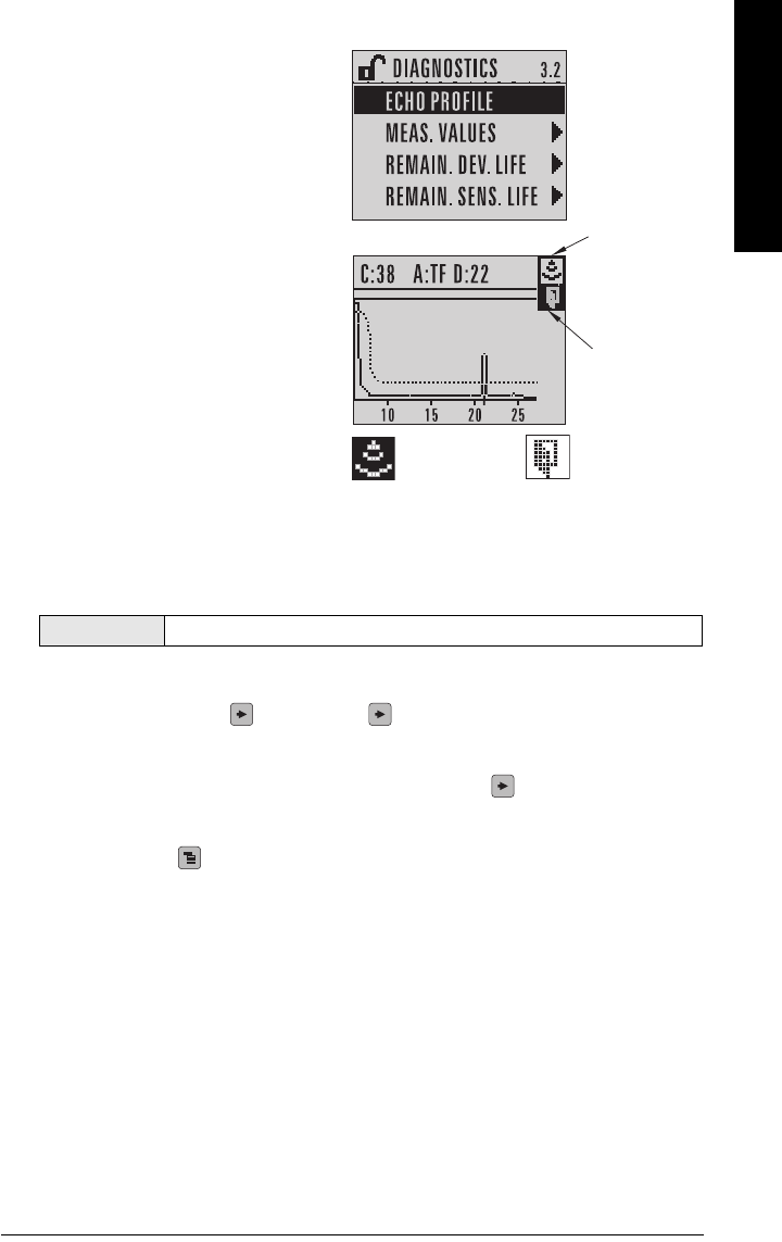
Requesting an Echo Profile
a) In PROGRAM mode, navigate to:
LEVEL METER > DIAGNOSTICS >
ECHO PROFILE (3.2)
b) Press RIGHT arrow to request a
profile.
c) In the Profile screen, press UP arrow
to select the Transmit icon, and
Right ARROW to update the profile.
d) Press DOWN arrow to select the Exit
icon, then Right ARROW to return to
previous menu.
Device Address
The unique address of the device on the network (also called PROFIBUS address).
a) In PROGRAM mode, navigate to: Level Meter > Communication > Device Address.
b) Press RIGHT arrow , RIGHT arrow , to open parameter view and enable Edit
mode.
c) If required, key in a new value and press RIGHT arrow to accept it. The LCD
displays the new value.
d) Press Mode to return to Measurement mode.
Auto False Echo Suppression
If SITRANS LR260 displays a false high level, or the reading is fluctuating between the
correct level and a false high level, you can use the Auto False Echo Suppression
parameters to prevent false echo detection. See TVT (Auto False Echo Suppression)
setup (2.2.4.) on page 61 for instructions.
Values 0 - 126. Default: 126
transmit icon,
selected
exit icon,
deselected
transmit icon,
deselected
exit icon,
selected
Page 36 SITRANS LR260 (PROFIBUS PA) – OPERATING INSTRUCTIONS A5E32337685
mmmmm
Quick Start: local
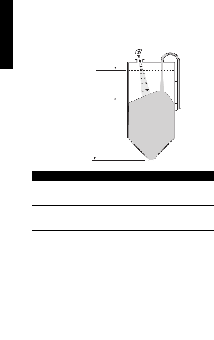
Level application example
Fill rate = 0.09 m/minute (Low Cal Pt. minus High Cal Pt.) / fastest fill/empty time
= (16 m – 0.5 m) / 180 min.
= 15.5 m /180 min. = 0.09 m/min.
Quick Start Setting Description
APPLICATION STEEL
RESPONSE RATE SLOW Response rate = 0.1 m/minute.
UNITS m
OPERATION LEVEL Material level referenced from Low Calibration Point.
LOW CALIBRATION POINT 16 Process empty level.
HIGH CALIBRATION POINT 0.5 Process full level.
APPLY? (CHANGES) YES Save new settings.
Sensor Reference Point
level
Low Calibration Point
High Calibration Point
16 m
0.5 m
SITRANS LR260
The application is a steel silo containing flour that takes an average of 3 hours to fill and
3 weeks to empty.
Using the Easy Aimer, the LR260 is oriented so that the emission cone is approximately
perpendicular to the material surface.

A5E32337685 SITRANS LR260 (PROFIBUS PA) – OPERATING INSTRUCTIONS Page 37
mmmmm
SIMATIC PDM
Operating via SIMATIC PDM
SIMATIC PDM is a software package used to commission and maintain SITRANS LR260 and
other process devices. Please consult the operating instructions or online help for details on
using SIMATIC PDM. (You can find more information at www.fielddevices.com: go to Products
and Solutions > Products and Systems > Communications and Software > Process Device
Manager.)
Functions in SIMATIC PDM
SIMATIC PDM monitors the process values, alarms and status signals of the device. It allows
you to display, compare, adjust, verify, and simulate process device data.
For information on adjusting parameter values and viewing the results, see
Changing
parameter settings using SIMATIC PDM
on page 42 and
Parameters accessed via pull-down
menus
on page 42.
Features of SIMATIC PDM Rev. 6.0, SP3 (or higher)
The graphic interface in SITRANS LR260 makes monitoring and adjustments easy:
• The graphic Quick Start Wizard provides an easy 4-step guide to help you configure
the device for a simple application. See
Quick Start Wizard via SIMATIC PDM
on
page 39 for instructions.
•See
Display
on page 43 to monitor process variables.
•See
Echo profile
on page 43 for easy echo profile comparison.
•See
Trend
on page 46 for Level trend monitoring.
•See
Auto False Echo Suppression
on page 44 and
TVT Shaper
on page 45 on
adjusting the TVT curve to avoid false echoes.
•See
Simulation
on page 46 for simulating process values during commissioning/
maintenance.
Note: For a complete list of parameters with instructions, see
Parameter Reference
starting on page 51.
Note:
• While the device is in PROGRAM mode, the output remains active and continues to
respond to changes in the device.
• Do not use the handheld programmer at the same time as SIMATIC PDM, or erratic
operation may result.

Page 38 SITRANS LR260 (PROFIBUS PA) – OPERATING INSTRUCTIONS A5E32337685
mmmmm
SIMATIC PDM
Electronic Device Description (EDD)
You can locate the EDD in Device Catalog, under Sensors/Level/Echo/Siemens Milltronics/
SITRANS LR260. Check the product page of our website at: www.siemens.com/LR260, under
Downloads, to make sure you have the latest version of SIMATIC PDM, the most recent
Service Pack (SP) and the most recent hot fix (HF). If you need to install a new EDD see
Configuring a new device
on page 38
Configuring a new device
1. Check that you have the most recent EDD that applies to your device version, and if
necessary download it from the product page listed above. Save the files to your
computer, and extract the zipped file to an easily accessed location. Launch SIMATIC
PDM – Manage Device Catalog, browse to the unzipped EDD file and select it.
2. Set Address via handheld programmer (default for PROFIBUS PA is 126). (See
Device
Address
on page 88 to use SIMATIC PDM.)
• Point the handheld programmer at the display then press Mode to activate
PROGRAM mode, menu item 1.0.
• Press DOWN arrow , RIGHT arrow , RIGHT arrow to navigate to
5.1.Device Address
.
• Press RIGHT arrow to open Edit mode: the PROGRAM icon will flash.
• If required, key in a new value and press RIGHT arrow to accept it. The LCD
displays the new value and the PROGRAM icon disappears.
• Press Mode to return to Measurement mode.
3. Launch SIMATIC Manager and create a new project for LR260. Application Guides
for setting up PROFIBUS PA devices with SIMATIC PDM can be downloaded from
the product page of our website at: www.siemens.com/LR260.
4. Open the menu Device – Device Reset and click on Factory Defaults.
5. After the reset is complete click on Close, then upload parameters to the PC/PG.
6. Calibrate the device.
Note: SITRANS LR260 requires the EDD for SIMATIC PDM version 6.0 with SP3 or
higher.
Note: Clicking on Cancel during an upload from device to SIMATIC PDM will result in
some parameters being updated.
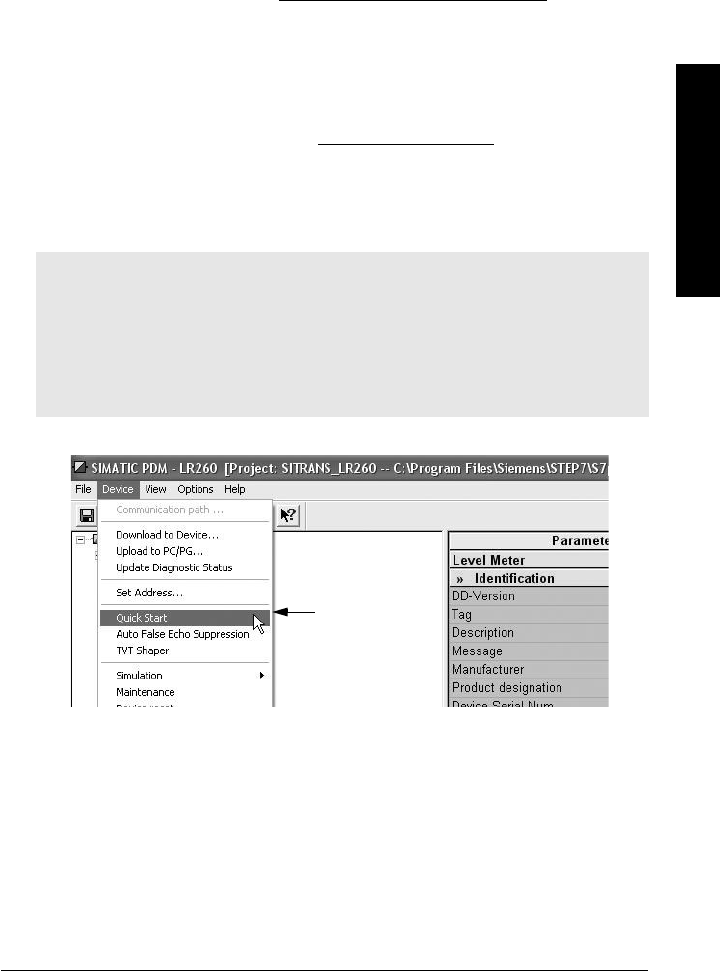
A5E32337685 SITRANS LR260 (PROFIBUS PA) – OPERATING INSTRUCTIONS Page 39
mmmmm
SIMATIC PDM
Quick Start Wizard via SIMATIC PDM
The graphic Quick Start Wizard provides an easy 4-step guide to help you configure the
device for a simple application.
Please consult the operating instructions or online help for details on using SIMATIC
PDM. (Application Guides for setting up Siemens PROFIBUS PA devices with SIMATIC
PDM are available on our website: www.siemens.com/processautomation.)
1. If you have not already done so, check that you have the most up-to-date Electronic
Device Description (EDD) for your instrument. (See
Configuring a new device
on
page 38.)
2. Launch SIMATIC Manager and create a new project for LR260. Application Guides
for setting up PROFIBUS PA devices with SIMATIC PDM can be downloaded from
the product page of our website at: www.siemens.com/LR260.
3. Upload parameters to the PC/PG.
4. Configure the device via the Quick Start Wizard.
Quick Start Wizard steps
Launch SIMATIC PDM, open the menu Device – Quick Start, and follow steps 1 to 4.
Notes:
• The Quick Start wizard settings are inter-related and changes apply only after you
click on Transfer at the end of step 4.
• Do not use the Quick Start Wizard to modify individual parameters: see instead
Parameter Reference
on page 51 (perform customization only after the Quick Start
has been completed).
• Click on BACK to return and revise setting or Cancel to exit the Quick Start.
Quick
Start
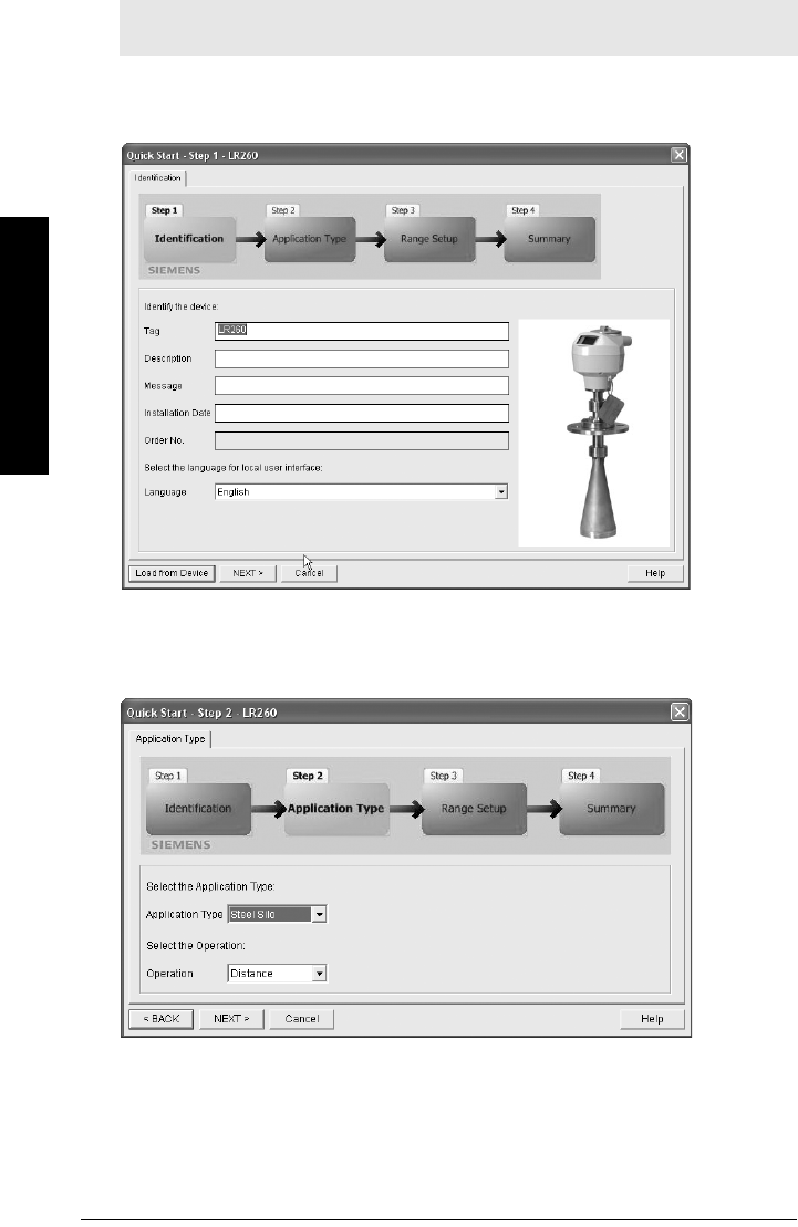
Page 40 SITRANS LR260 (PROFIBUS PA) – OPERATING INSTRUCTIONS A5E32337685
mmmmm
SIMATIC PDM
Step 1 – Identification
Click on NEXT to accept the default values. (Description, Message, and Installation Date
fields can be left blank.)
Step 2 – Application Type
Select the application type and the operation, then click on NEXT.
Note: The layout of the dialog boxes shown may vary according to the resolution
setting for your computer monitor.
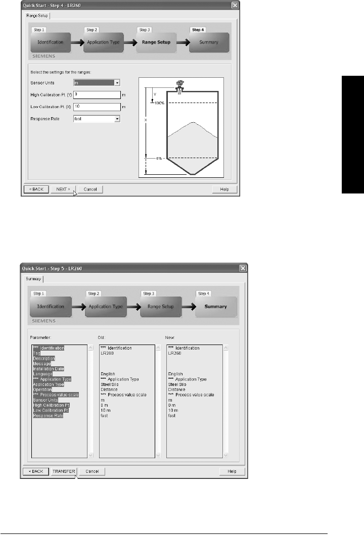
A5E32337685 SITRANS LR260 (PROFIBUS PA) – OPERATING INSTRUCTIONS Page 41
mmmmm
SIMATIC PDM
Step 3 – Range Setup
Set the parameters, and click on NEXT.
Step 4 – Summary
Check parameter settings, and click on BACK to return and revise values, or TRANSFER
to transfer values to the device.
The message Quick Start was successful will appear. Click on OK, then click on OK again to
synchronize with the device.
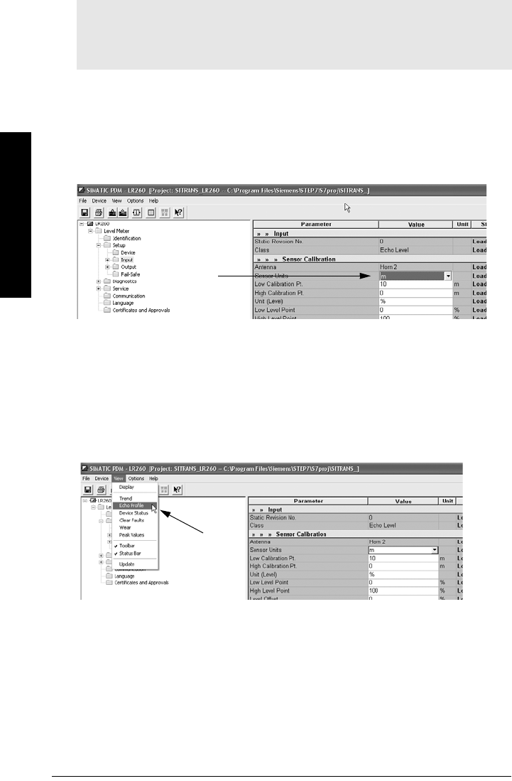
Page 42 SITRANS LR260 (PROFIBUS PA) – OPERATING INSTRUCTIONS A5E32337685
mmmmm
SIMATIC PDM
Changing parameter settings using SIMATIC PDM
1. Launch SIMATIC PDM, connect to SITRANS LR260, and upload data from the device.
2. Adjust parameter values in the parameter value field then press Enter. The status
fields read Changed.
3. Open the Device menu, click on Download to Device, then use File – Save, to save
parameter settings. The status fields are cleared.
Parameters accessed via pull-down menus
You have access to a number of functions via pull-down menus from the menu bar. under
Device or View.
For a complete list, see
Pull-down menus via SIMATIC PDM
on page 51.
Notes:
• For a complete list of parameters, see
Parameter Reference
on page 51.
• Clicking on Cancel during an upload from device to SIMATIC PDM will result in some
parameters being updated.
value
fields
pull-
down
menus
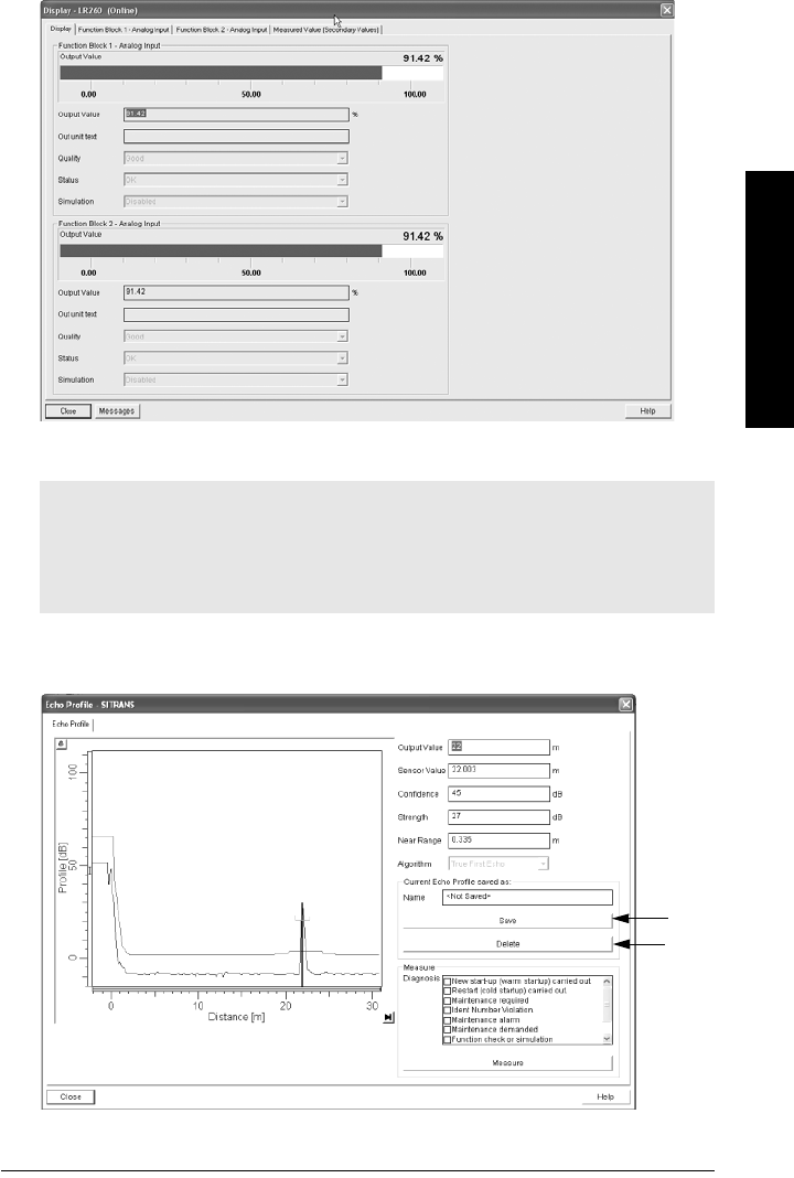
A5E32337685 SITRANS LR260 (PROFIBUS PA) – OPERATING INSTRUCTIONS Page 43
mmmmm
SIMATIC PDM
Display
To compare outputs in real time, open the menu View – Display.
Echo profile
Open the menu View - Echo Profile.
Notes:
• Record the default X-Scale (horizontal axis) and Data Scale (vertical axis) values so
that you can restore the default view by resetting to these values.
• You can save a profile or delete a saved profile.
• After saving a profile open menu View – Show echo profile.
delete
save

Page 44 SITRANS LR260 (PROFIBUS PA) – OPERATING INSTRUCTIONS A5E32337685
mmmmm
SIMATIC PDM
Auto False Echo Suppression
SITRANS LR260 first learns the echo profile. Then the learned profile, or part of it, is used to
screen out false echoes. (See
Auto False Echo Suppression
on page 105 for a more detailed
explanation.)
1. Determine Auto Suppression Range (the distance within which the learned TVT will
replace the default TVT). Measure the actual distance from the antenna reference
point to the material surface using a rope or tape measure, and make allowances
for the actual location of the LR260. Subtract 2 m (6.56 ft) from this distance, and use
the resulting value.
2. Open the menu Device – Auto False Echo Suppression.
3. Enter the value for Auto Suppression Range and click on Set Range.
4. Click on Learn. While the new curve is being learned, all buttons are inaccessible.
Unless calculation is instantaneous, buttons will disappear until it is complete.
5. When the buttons are visible, click on Close. Auto TVT is now on, and the learned
TVT curve will be used.
6. To turn Auto False Echo Suppression off or on, re-open menu Device – Auto False
Echo Suppression and click on Off or On.
Notes:
• If possible, adjust Auto False Echo Suppression parameters with an empty or almost
empty vessel. There should be a minimum distance of 2 meters from the radar
instrument to the material.
• Set Auto False Echo Suppression and Auto Suppression Range during installation, if
possible.
• Before adjusting these parameters, rotate the instrument for best signal (minimum
false-echo amplitude).
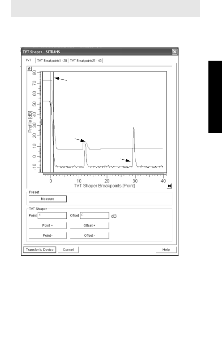
A5E32337685 SITRANS LR260 (PROFIBUS PA) – OPERATING INSTRUCTIONS Page 45
mmmmm
SIMATIC PDM
TVT Shaper
This feature allows you to manually adjust the TVT curve to avoid false echoes caused by
obstructions. (For an explanation see
Auto False Echo Suppression
on page 105.)
Open the menu Device – TVT Shaper
• Press Measure to refresh the echo profile and load the current TVT curve from the
device.
• Change the position of the cursor on the TVT curve using the Point+ and Point–
buttons: raise and lower the curve using Offset+ and Offset– (entered in dB).
• Alternatively, enter values for Point and Offset directly into the dialog boxes.
• If desired, click on the TVT breakpoints tabs to see settings.
• Then press Transfer to Device.
Note: Record the default X-Scale (horizontal axis) and Data Scale (vertical axis) values
so that you can restore the default view by resetting to these values.
TVT curve
cursor
echo profile
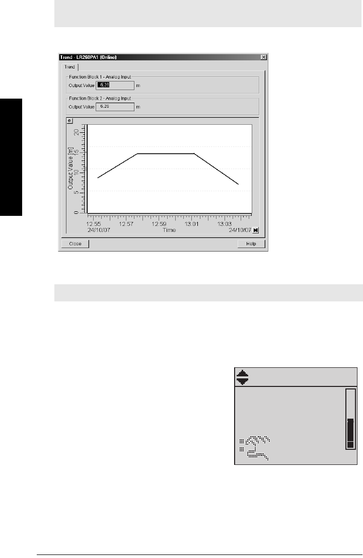
Page 46 SITRANS LR260 (PROFIBUS PA) – OPERATING INSTRUCTIONS A5E32337685
mmmmm
SIMATIC PDM
Trend
Open the menu View – Trend
Simulation
Simulate Analog Input to AIFB1 or AIFB2
Allows you to input a simulated value in order to test the functioning of the Analog Input
Function Blocks.
1. Open the menu Device – Simulation, and
select the desired function block.
2. Enable simulation.Click on Transfer.
3. Enter a value, quality, status, and click on
Transfer. The LCD displays the substitute
value.
4. After simulation is complete, disable
simulation.
Note: Record the default X-Scale (horizontal axis) and Data Scale (vertical axis) values
so that you can restore the default view by resetting to these values.
Note: The Simulation parameter influences output to the control system.
trend line
PERCENT
[]
AIFB 1
21.40 °C
SUBSTITUTE VAL.
40.61

A5E32337685 SITRANS LR260 (PROFIBUS PA) – OPERATING INSTRUCTIONS Page 47
mmmmm
SIMATIC PDM
Simulate Input
Allows you to simulate the sensor value which is input to the Level Transducer Block. This
tests everything between the Level Transducer Block and Output.
1. Open the menu Device – Simulation, and select Simulation (Input).
2. To enable simulation select Fixed or Ramp.
If you select Ramp, enter the Ramp start and end, step length and number of
steps. Click on Transfer.
If you select Fixed, enter the simulated value and click on Transfer.
3. After simulation is complete, disable simulation.
Device Reset
To perform a reset to Factory Defaults:
1. Open the menu Device – Device Reset, and click on Factory Defaults.
2. After the reset is complete, click on Close, then upload parameters to the PC/PG.
(If you are performing a reset after replacing the device with a different
instrument, do not upload parameters to the PC/PG.)
Write Locking
If Write Locking is enabled, the data can be viewed but not modified. See
Write Locking
(6.1.)
on page 88 for more details.
To enable/disable Write Locking:
1. Open the menu Device – Write Locking and select On or Off.
2. Click on Transfer.
Reset options Result
Factory Defaults Resets all parameters excluding Device Address , Tag,
Description, Message, and Installation Date to the
manufacturer’s default settings.
Standard Defaults Resets all parameters excluding Device Address, Description,
Message, and Installation Date to the PROFIBUS default
settings
Informational Resets parameter Tag
Functional Resets parameters that control device behavior, such as Low
Calibration Pt.
Warm Start Has the same effect as recycling power to the device
Reset Device Address
to 126
• Resets the PROFIBUS device address to 126
• If the address lock was on, will disable the lock.
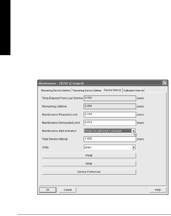
Page 48 SITRANS LR260 (PROFIBUS PA) – OPERATING INSTRUCTIONS A5E32337685
mmmmm
SIMATIC PDM
Maintenance
You can set schedules for:
• maintenance of the device based on its projected lifetime
• maintenance of the sensor based on its projected lifetime
•service
• calibration
To set Device/Sensor Maintenance schedules:
1. Open the menu Device – Maintenance, and click on the Remaining Device/
Sensor Lifetime tab.
2. If desired, activate alerts for either or both of Maintenance Required/
Maintenance Demanded.
3. Modify desired values, and click on Write.
4. Click on Read, to see the effects of your modification.
5. Click on Snooze to add a year to the Total Expected Device Life.
To set Service/Calibration schedules:
1. Open the menu Device – Maintenance, and click on the Service/Calibration
Interval tab.
2. If desired, activate alerts.
3. Modify desired values, and click on Write.
4. Click on Read, to see the effects of your modification.
5. Click on Service Performed to reset the schedule.
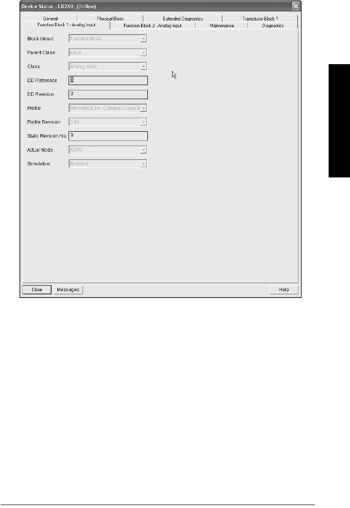
A5E32337685 SITRANS LR260 (PROFIBUS PA) – OPERATING INSTRUCTIONS Page 49
mmmmm
SIMATIC PDM
Device Status
Open the menu View – Device Status and click on the appropriate tab to monitor
maintenance and diagnostics conditions.
Wear
Open the menu View – Wear to view:
• Powered Hours
• Power-on Resets
Peak Values
Open the menu View – Peak Values to view:
• Sensor minimum and maximum Measured Values
• Minimum and maximum Output Values for AIFB1 and AIFB2
• Minimum and maximum Internal Temperatures

Page 50 SITRANS LR260 (PROFIBUS PA) – OPERATING INSTRUCTIONS A5E32337685
mmmmm
SIMATIC PDM
Notes

A5E32337685 SITRANS LR260 (PROFIBUS PA) – OPERATING INSTRUCTIONS Page 51
mmmmm
Parameters
Parameter Reference
Parameters are identified by name and organized into function groups. Menus arranged
on up to five levels give access to associated features and options. (See
LCD menu
structure
on page 141 for a chart.)
Parameters accessible via the handheld programmer are preceded by a number.
Parameters not preceded by a number are accessible only via SIMATIC PDM.
Some parameters are accessible in SIMATIC PDM via pull-down menus. Where those
parameters can also be accessed via the handheld programmer, they are found in the
numbered list, and directions for SIMATIC PDM are given below the individual parameter.
Page references for further information on using these features via SIMATIC PDM can be
found in the table below.
Pull-down menus via SIMATIC PDM
Notes:
• See
Programming via the handheld programmer
on page 30
for
detailed instructions.
• In Navigation mode, ARROW keys navigate the menu in the
direction of the arrow.
•Press RIGHT Arrow to open Edit Mode, or to save a modification.
•Mode key toggles between PROGRAM and Measurement Modes.
Device menus page View menus page
Communication path - Display -
Download to device
Upload to PC/PG
Update diagnostic status
-
-
-
Trend
Echo profile
Show Echo profile
Device Status
Clear Faults
Wear
Peak Values
46
43
-
49
-
49
49
Set Address Tool ba r
Status bar
Quick Start
Auto False Echo Suppression
TVT Shaper
39
44
45
Update
Simulation
Maintenance
Device Reset
Write Locking
46
48
47
47

Page 52 SITRANS LR260 (PROFIBUS PA) – OPERATING INSTRUCTIONS A5E32337685
mmmmm
Parameters
Quick Start Wizard
The Quick Start wizard groups together all the settings you need to configure for a simple
application. You can access it either via SIMATIC PDM, or via the handheld programmer.
• The Quick Start wizard is a complete package and settings are inter-related.
• Do not use the Quick Start wizard to modify individual parameters.
• Perform customization of the device only after the Quick Start is completed.
1. Quick Start
1.1. Application Type
1.2. Response Rate
Sets the reaction speed of the device to measurement changes in the target range.
Use a setting just faster than the maximum filling or emptying rate (whichever is
greater). Slower settings provide higher accuracy, faster settings allow for more level
fluctuation.
1.3. Units
Select the units for the Quick Start variables (high and low calibration point, and level,
distance, or space).
1.4. Operation
Options
STEEL Silo construction
CONCRETE
Default: STEEL
Options
SLOW 0.1 m/minute
MED 1.0 m/minute
FAST 10.0m/minute
Default: FAST
Options M, CM, MM, FT, IN
Default: M
Options
NO
SERVICE
SITRANS LR260 stops updating measurements. Last valid
measurement value is displayed.
LEVEL Distance to material surface referenced from Low Calibration
Point (process empty level).
SPACE Distance to material surface referenced from High Calibration
Point (process full level).
DISTANCE Distance to material surface referenced from Sensor Reference
Point.
Default: DISTANCE

A5E32337685 SITRANS LR260 (PROFIBUS PA) – OPERATING INSTRUCTIONS Page 53
mmmmm
Parameters
Operation types
1.5. Low Calibration Point (LOW CALIB. PT.)
Distance from Sensor Reference to Low Calibration Point: usually process empty
level.
1.6. High Calibration Point (HIGH CALIB. PT.)
Distance from Sensor Reference to High Calibration Point: usually process full level.
1.7. Apply? (Apply changes)
In order to save the Quick Start settings it is necessary to select Yes and apply
changes.
• Display shows DONE when Quick Start is successfully completed.
• Press Mode to return to Measurement mode.
Values Range: 0.000 to 30.000 m
Default: horn type dependent
Values Range: 0.000 to 30.000 m
Default: 0.0 m
Options NO, YES, DONE
high
calibration
point
low calibration point
level
space
distance
sensor reference point
(flange face)

Page 54 SITRANS LR260 (PROFIBUS PA) – OPERATING INSTRUCTIONS A5E32337685
mmmmm
Parameters
2. Setup
2.1. Device
2.1.1. Tag
Text that can be used in any way. A recommended use is as a unique label for
a field device in a plant. Limited to 32 ASCII characters. Read only on device,
Read/Write using SIMATIC PDM.
2.1.2. Description
Text that can be used in any way. Limited to 32 ASCII characters. No specific
recommended use. Read only on device, Read/Write using SIMATIC PDM.
2.1.3. Message
Text that can be used in any way. Limited to 32 ASCII characters. No specific
recommended use. Read only on device, Read/Write using SIMATIC PDM.
2.1.4. Firmware Revision (FIRMWARE REV.)
Corresponds to the software or firmware that is embedded in the Field Device.
Read only.
2.1.5. Loader Revision (LOADER REV.)
Corresponds to the software used to update the Field Device. Read only.
2.1.6. Hardware Revision (HARDWARE REV.)
Corresponds to the electronics hardware of the Field Device. Read only.
2.2. Input
2.2.1. Sensor Calibration (SENSOR CALIB.)
2.2.1.1. Antenna
Displays antenna type.
2.2.1.2. Sensor Units
Sets engineering units to be used by the sensor for measurement.
Notes:
• See
Programming via the handheld programmer
on page 30 or
Operating via
SIMATIC PDM
on page 37 for instructions.
• Default settings in the parameter tables are indicated with an asterisk (*) unless
explicitly stated.
• Values shown in the following tables can be entered via the handheld programmer.
Values
(view only)
No Horn, Horn 2, Horn 3, Horn 4
Default is set by factory depending on horn size.
Values M, CM, MM, FT, IN
Default: m

A5E32337685 SITRANS LR260 (PROFIBUS PA) – OPERATING INSTRUCTIONS Page 55
mmmmm
Parameters
2.2.1.3. Low Calibration Pt. (LOW CALIB. PT.)
Distance from Sensor Reference to Low Calibration Point (corresponding to
Low Level Point). Unit is defined in Sensor units.
1)
2.2.1.4. High Calibration Pt. (HIGH CALIB. PT.)
Distance from Sensor Reference to High Calibration Point (corresponding
to High Level Point). Unit is defined in Sensor units.
2.2.1.5. Limit Sensor Value
When ON, limits sensor value to the range between Low Calibration Point
and High Calibration Point.
2.2.1.6. Unit (Level)
Select engineering units for Level.
2.2.1.7. Low Level Point
The level when the material is at Low Calibration Point. The unit is defined
in Level units.
2.2.1.8. High Level Point
The level when the material is at High Calibration Point. The unit is defined
in Level units.
2.2.1.9. Level Offset
A constant offset that can be added to Level. The unit is defined in Level
units.
Values Range: 0 to 30 m. Default: 30.000 m (dependent on horn type)
1) The point from which level measurement is referenced (see
Dimensions
on page 9).
Values Range: 0 to 30 m. Default: 0.000 m
Options ON, OFF
Default: ON
Options M, CM, MM, FT, IN, Percent
Default: Percent
Values Default: 0%
Values Default: 100%
Values Default: 0%

Page 56 SITRANS LR260 (PROFIBUS PA) – OPERATING INSTRUCTIONS A5E32337685
mmmmm
Parameters
2.2.1.10. Sensor Offset
A constant offset that can be added to the sensor value to compensate if
the sensor has been changed. The units is defined in Sensor Units. (See
Transducer block function groups on page 114 and How the LTB works on
page 114 for more detail.)
2.2.1.11. Temperature Units (TEMP UNITS)
Selects the engineering unit to be displayed with the value representing
temperature.
2.2.3. Echo Processing (ECHO PROC)
2.2.3.1. Echo select
2.2.3.1.1. Algorithm
Selects the algorithm to be applied to the echo profile to extract the
true echo.
Values Range: - 999.99 to 999.99 m
Default: 0 m
Options DEG C, DEG F, RANKINE, KELVIN
*DEG C
Options
ALF Area Largest First
AEcho Area
LLargest Echo
FFirst echo
AL Area Largest
AF Area First
LF Largest First
BLF Best of Largest or First echo
BL Best Largest
BF Best First
LAST Last echo
*TF True First

A5E32337685 SITRANS LR260 (PROFIBUS PA) – OPERATING INSTRUCTIONS Page 57
mmmmm
Parameters
2.2.3.1.2. Echo Threshold
Sets the minimum echo confidence that the echo must meet in order
to prevent a Loss of Echo condition and the expiration of the LOE
timer. When Echo Confidence (2.2.3.6.1.) exceeds the Echo Threshold
(2.2.3.1.2.), the echo is accepted as a valid echo and evaluated.
Use this feature when an incorrect material level is reported.
2.2.3.1.3. Position
Defines where on the echo the distance measurement is determined.
(See Echo Position Detection on page 104 for more detail.)
2.2.3.1.4. Echo Marker
The point on the selected echo from which the measured value is
taken.
When SITRANS LR260 is using Rising Edge, higher values will cause
lower level readings and lower values will cause higher level
readings.
Values Range: 0 to 99 dB
Default: 10 dB
Related
Parameters LOE Timer (2.4.1.)
Options
Rising Edge
*Center of Mass (COM)
Hybrid (Center and CLEF)
CLEF (Constrained Leading Edge Fit)
Values Range: 5 to 95%
Default: 70%
Related
Parameters Position (2.2.3.1.3.)

Page 58 SITRANS LR260 (PROFIBUS PA) – OPERATING INSTRUCTIONS A5E32337685
mmmmm
Parameters
2.2.3.2. Sampling
Provides a method of checking the reliability of a new echo before
accepting it as the valid reading, based on numbers of samples above or
below the currently selected echo.
2.2.3.2.1. Echo Lock
Selects the measurement verification process. See Echo Lock on
page 104 for more details.
2.2.3.2.2. Up sampling (UP SAMP.)
Specifies the number of consecutive echoes that must appear above
the echo currently selected, before the measurement is accepted as
valid.
2.2.3.2.3. Down sampling (DOWN SAMP.)
Specifies the number of consecutive echoes that must appear below
the echo currently selected, before the measurement is accepted as
valid.
Options
Lock Off (no verification)
*Maximum Verification
Material Agitator
Tot al Lock a)
a) When Echo Lock is set to Total Lock, the Echo Lock Window is
preset to 0 for automatic width and cannot be changed.
Related
parameters
Fill Rate (FILL RATE/MIN) (2.2.6.2.)
Empty rate (EMPTY RATE/MIN) (2.2.6.3.)
Up sampling (UP SAMP.) (2.2.3.2.2.)
Down sampling (DOWN SAMP.) (2.2.3.2.3.)
Window (2.2.3.2.4.)
Algorithm (2.2.3.1.1.)
Values Range: 1 to 50
Default: 5
Values Range: 1 to 50
Default: 5

A5E32337685 SITRANS LR260 (PROFIBUS PA) – OPERATING INSTRUCTIONS Page 59
mmmmm
Parameters
2.2.3.2.4. Window
A “distance window” centered on the echo
1)
is used to derive the
reading. When a new measurement is in the window, the window is
re-centered and the reading is calculated.
When the value is 0, the window is automatically calculated after
each measurement.
• For slower Measurement Response values, the window is
narrow.
• For faster Measurement Response values, the window
becomes progressively wider.
2.2.3.3. Filtering
2.2.3.3.1. Shots
The number of echo profile samples averaged to produce a
measurement.
2.2.3.3.2. Narrow Echo Filter (NARROW ECHO FIL.)
Filters out echoes of a specific width
To remove a false echo from the Echo Profile, take its width in mm
and multiply it by 0.013. Enter the result.
For example, to filter out a spike with 500 mm width, enter 6 or 7 (the
closest integer product of 500 x 0.013).
When a value is keyed in, the nearest acceptable value is entered.
1) See
Echo Lock
on page 104 for more detail.
Values Range: 0 to 31.5 m
Default: 0 m
Note: The Echo Lock window is stored as a standard sample, but
displayed in sensor units. Any value entered for the Echo Lock
window will be rounded to the nearest sample.
Values Range: 1 to 25
Default: 10
Values
Range: 0 to 255
0 = OFF
greater = wider
Default: 0 (OFF)
Related
parameters
2.2.3.3.3. Reform Echo

Page 60 SITRANS LR260 (PROFIBUS PA) – OPERATING INSTRUCTIONS A5E32337685
mmmmm
Parameters
2.2.3.3.3. Reform Echo
Smooths jagged peaks in the echo profile. Reforms fragmented
echoes into one echo.
2.2.3.5. Range
2.2.3.5.1. Near Range
The range in front of the device (measured from the sensor reference
point
1)
) within which any echoes will be ignored. (This is sometimes
referred to as “Blanking” or “Dead Zone”.) The range is dependent
on the horn type and any extensions.
2.2.3.5.2. Far Range
Maximum distance from the reference point
1)
, within which an echo
should be considered valid.
Values
0 = OFF
greater = wider
Range: 0 to 50 mS
Recommended: 5 to 20 mS; higher is not
recommended.
Related parame-
ters
2.2.3.1.1. Algorithm
2.2.3.3.2. Narrow Echo Filter (NARROW
ECHO FIL.)
2.2.3.1.4. Echo Marker
1) See
Dimensions
on page 9.
Values
Factory Defaults
2" horn 0.21 m (8.43")
3" horn 0.28 m (10.95")
4" horn 0.34 m (13.19")
Range: 0 to 31.5 m
Note: Far Range can extend beyond the bottom of the vessel.
Values
Range: Min. = Low Calibration Pt.
Max. for 2" horn = 13 m (42.65 ft)
Max. for 3" horn = 23 m (75.46 ft)
Max. for 4" horn = 31.5 m (103.35 ft)
Default: Value for Low Calibration Pt. + 3 m
(9.43 ft)
Range: 0 to 31.5 m

A5E32337685 SITRANS LR260 (PROFIBUS PA) – OPERATING INSTRUCTIONS Page 61
mmmmm
Parameters
2.2.3.5.3. Min. Sensor Value (MIN. SENSOR VAL.)
The minimum value the device can measure in Sensor units.
2.2.3.5.4. Max. Sensor Value (MAX. SENSOR VAL.)
The maximum value the device can measure in Sensor units.
2.2.3.6. Noise
2.2.3.6.1. Echo Confidence
Indicates echo reliability: higher values represent better echo
quality. The display shows the echo confidence of the measurement
echo from the last shot. Confidence Threshold defines the minimum
criterion for echo confidence.
In PDM, open the menu View – Echo Profile.
2.2.3.6.2. Echo Strength
Displays the absolute strength (in dB referenced to 1 μV rms) of the
echo selected as the measurement echo.
In PDM, open the menu View – Echo Profile.
2.2.4. TVT (Auto False Echo Suppression) setup
First SITRANS LR260 learns the echo profile. Then the learned profile, or part of
the learned profile, is used to screen out false echoes. See Before Auto False
Echo Suppression on page 63 and After Auto False Echo Suppression on page
63 for examples.
2.2.4.1. TVT Type
Selects the TVT shaping type to be applied to the echo profile to extract
the true echo.
Values (view only) 0 to 99 dB
Related
Parameters Echo Threshold (2.2.3.1.2.)
Values (view only) –20 to 99 dB
Options
Short Curved
Short Flat
Long Flat
Long Smooth Front
Long Smooth
Slopes
*Long Smooth 2
Short Curved 2
Note: Changing the TVT type will reset the value of the TVT Hover
Level.

Page 62 SITRANS LR260 (PROFIBUS PA) – OPERATING INSTRUCTIONS A5E32337685
mmmmm
Parameters
2.2.4.2. TVT Hover Level1)
Defines how high the TVT (Time Varying Threshold) curve is placed above
the noise floor of the echo profile, as a percentage of the difference between
the peak of the largest echo in the profile and the noise floor. When
SITRANS LR260 is located in the center of the vessel, the TVT hover level
may be lowered to increase the confidence level of the largest echo.
(For an
illustration of the TVT curve see
Before Auto False Echo Suppression on
page 63.)
2.2.4.3. Auto False Echo Suppression (AUTO ECHO SUPP)
Enables a ’learned’ TVT curve to be used in place of the default TVT curve.
(See Auto False Echo Suppression
on page 105
for an explanation)
a) Determine Range (the distance within which the learned TVT will
replace the default TVT). Measure the actual distance from the
antenna reference point to the material surface using a rope or tape
measure, and make allowances for the actual location of the device.
b) Subtract 2 m (6.56 ft) from this distance, and use the resulting value.
To use Auto False Echo Suppression via SIMATIC PDM:
c) Open the menu Device – Auto False Echo Suppression and set
Range. For more detail see
Auto False Echo Suppression
on page
44.
d) Select Learn. The device will automatically revert to On (Use
Learned TVT) after a few seconds.
To set Auto False Echo Suppression via the handheld programmer:
c. Go to Auto Suppression Range (AUTO SUPP RANGE)(2.2.4.4.) and
enter new value.
c. Go to Auto False Echo Suppression (AUTO ECHO SUPP)(2.2.4.3.).
Press RIGHT ARROW to open Edit Mode.
d) Select Learn. The device will automatically revert to On (Use
Learned TVT) after a few seconds.
1) For an illustration, see
Before Auto False Echo Suppression
and
After Auto False Echo
Suppression
on page 63.
Values Range: 0 to 100%
Default: 33%
Notes:
• If possible adjust Auto False Echo Suppression parameters with an
empty or almost empty vessel.
• Set Auto False Echo Suppression and Auto False Echo Range during
startup, if possible.
• If the vessel contains an agitator, the agitator should be running.
Options
OFF Default TVT curve will be used.
* ON ’Learned’ TVT curve will be used.
LEARN ’Learn’ the TVT curve.
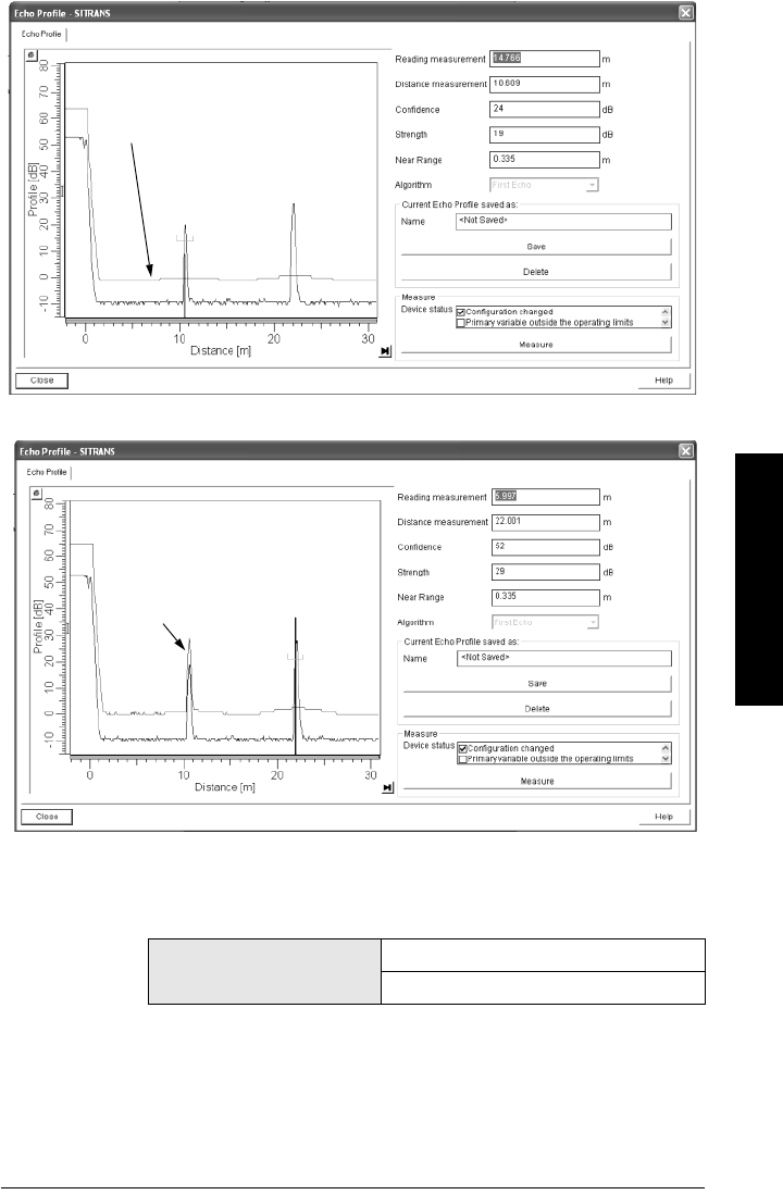
A5E32337685 SITRANS LR260 (PROFIBUS PA) – OPERATING INSTRUCTIONS Page 63
mmmmm
Parameters
.
2.2.4.4. Auto Suppression Range (AUTO SUPP RANGE)
Defines the endpoint of the Learned TVT distance. Units are defined in
sensor units.
a) Press RIGHT ARROW to open Edit mode.
b) Enter the new value and press RIGHT ARROW to accept it.
c) Set Auto False Echo Suppression (AUTO ECHO SUPP)(2.2.4.3.)
Values Range: 0.00 to 31.50 m
Default: 1.0 0 m
echo
marker
echo
marker
default
TVT
After Auto False Echo Suppression
level
learned
TVT curve
false echo
Before Auto False Echo Suppression

Page 64 SITRANS LR260 (PROFIBUS PA) – OPERATING INSTRUCTIONS A5E32337685
mmmmm
Parameters
2.2.4.5. Shaper Mode
Enables/disables TVT Shaper(2.2.5.).
2.2.5. TVT Shaper
A breakpoint on the TVT curve. This allows you to reshape the TVT curve to
avoid unwanted echoes. There are 40 breakpoints arranged in 5 groups. (We
recommend using SIMATIC PDM to access this feature.)
To use TVT shaper via LUI (local user interface):
a) Go to Shaper Mode(2.2.4.5.) and select option ON.
b) In TVT Shaper, go to Shaper 1-9(2.2.5.1.).
c) Open Shaper 1 and enter the TVT Offset value (between -100 to 100 bits,
inclusive).
d) Go to the next Shaper point and repeat step (c) until all desired breakpoint
values have been entered.
2.2.5.1. Shaper 1-9
2.2.5.2. Shaper 10-18
2.2.5.3. Shaper 19-27
2.2.5.4. Shaper 28-36
2.2.5.5. Shaper 37 - 40
To access TVT shaper via SIMATIC PDM:
• Open the menu Device – TVT shaper.
• For more details and an illustration see
TVT Shaper
on page 45.
Options OFF*, ON
Note: The range is -100 to 100 bits. With 2 bits per dB, this gives a range of
-50 to 50 dB.
Values Range: -100 to 100 bits
Default: 0 bits
Values Range: -100 to 100 bits
Default: 0 bits
Values Range: -100 to 100 bits
Default: 0 bits
Values Range: -100 to 100 bits
Default: 0 bits
Values Range: -100 to 100 bits
Default: 0 bits

A5E32337685 SITRANS LR260 (PROFIBUS PA) – OPERATING INSTRUCTIONS Page 65
mmmmm
Parameters
2.2.6. Rate
2.2.6.1. Response Rate
Sets the reaction speed of the device to measurement changes.
.
Use a setting just faster than the maximum filling or emptying rate
(whichever is greater). Slower settings provide higher accuracy; faster
settings allow for more level fluctuation.
2.2.6.2. Fill Rate (FILL RATE/MIN)
Defines the maximum rate at which the reported sensor value is allowed to
increase. Allows you to further adjust the SITRANS LR260 response to
increases in the rate at which the vessel fills.
Enter a value slightly greater than the maximum vessel-filling rate, in
Sensor Units per minute.
Related
paramet
ers
Response
Rate(2.2.6
.1.)
Fill Rate
(FILL
RATE/
MIN)(2.
2.6.2.)
Empty
rate
(EMPTY
RATE/
MIN)(2.2.
6.3.)
Filter
Time
Constant
(FILTER
TIME
CONST)(
2.3.1.4.)a)
a) Numbering depends on AIFB selected.
Shots(2.2
.3.3.1.)
Options
slow 0.1 m/min-
ute
0.1 m/min-
ute 60 s 25
medium 1 m/minute 1 m/minute 10 s 10
*fast 10 m/min-
ute 10 m/minute 0 s 10
Note: Changing Response Rate resets Fill Rate, Empty Rate, Filter Time
Constant and Shots.
Note: Fill Rate is automatically updated whenever Response
Rate(2.2.6.1.) is altered.
Options
Range: 0 to 999.99 m/min
Slow 0.1 m/min.
Medium 1 m/min.
*Fast 10 m/min.
Altered by: Response Rate (2.2.6.1.)
Related parameters Unit (Level) (2.2.1.6.)

Page 66 SITRANS LR260 (PROFIBUS PA) – OPERATING INSTRUCTIONS A5E32337685
mmmmm
Parameters
2.2.6.3. Empty rate (EMPTY RATE/MIN)
Defines the maximum rate at which the reported sensor value is allowed to
decrease. Adjusts the SITRANS LR260 response to decreases in the rate at
which the vessel empties.
Enter a value slightly greater than the vessel’s maximum emptying rate, in
Sensor Units per minute.
2.2.7. Transducer Block Values (for diagnostic purposes)
2.2.7.1. Main Output (PV– Primary Value)
The value for level/volume. Read Only.
In SIMATIC PDM, open the menu View – Display, and select the tab
Measured Value (Secondary Values). Refer to Level/Volume field.
2.2.7.2. Output, no linearization (SV1 – Secondary Value 1)
The value for level. Read Only.
In SIMATIC PDM, open the menu View – Display, and select the tab
Measured Value (Secondary Values). Refer to Level/Volume field.
2.2.7.3. Output, no level offset (SV2 – Secondary Value 2)
The value for distance. Read Only.
In SIMATIC PDM, open the menu View – Display, and select the tab
Measured Value (Secondary Values). Refer to Distance field.
2.3. Output
2.3.1. AIFB1
Static Revision No.
The revision level of the static data associated with Analog Input Function
Block 1. The Static Revision No. is updated whenever a configuration
parameter is changed.
Note: Empty Rate is automatically updated whenever Response
Rate(2.2.6.1.) is altered
Options
Range: 0 to 999.99 m/min.
Slow 0.1 m/min.
Medium 1 m/min.
*Fast 10 m/min.
Altered by: Response Rate (2.2.6.1.)
Related parameters Unit (Level) (2.2.1.6.)

A5E32337685 SITRANS LR260 (PROFIBUS PA) – OPERATING INSTRUCTIONS Page 67
mmmmm
Parameters
2.3.1.1. Target Mode
Used to request an operating mode from the Function Block.
Allows you to put the SITRANS LR260 into Out of Service Mode and then
reset it to Automatic Mode.
Manual Mode is used in conjunction with Simulation. See
Simulation
on
page 46. It should be used only with SIMATIC PDM in order to benefit from
all the features available.
2.3.1.2. Label
User defined label
2.3.1.3. Unit
Engineering unit to be displayed with the output value
2.3.1.4. Filter Time Constant (FILTER TIME CONST)
The time constant for the damping filter. (See Damping on page 106
for
more detail.
)
The engineering unit is always in seconds. (This is an
exponential filter: when a change occurs at the input, the output will be at
63.2% of the change in one time constant, and will be at full change after 5
time constants.)
2.3.1.5. Channel
Used to select between the different Level Transducer Block outputs.
When volume is not supported, the Primary Variable (Level/Volume) will
have alternate functionality. It is possible to configure the Transducer
Block outputs so that PV/SV1 is not always a level output.
2.3.1.6. Batch Information (BATCH INFO)
These 4 parameters are intended to be used in Batch Applications
conforming to IEC 61512 Part 1 (ISA S88). Other applications do not require
these values, which are only stored in the Function Block.
Options
*Automatic Mode (AUTO)
Manual Mode (MAN)
Out of Service (O/S)
Note: Additional units are available in SIMATIC PDM.
Options
m, cm, mm, ft, in, percent, Follow out unit (device only)
m, cm, mm, ft, in, L, gal, imp gal, percent, Not Used, Unknown,
Special, " ", Follow out unit (SIMATIC PDM)
*m
Values Range 0 to 1000 s
Default: 0 s
Options Level/Volume (PV), Level (SV1), Distance (SV2)
*Distance (SV2)

Page 68 SITRANS LR260 (PROFIBUS PA) – OPERATING INSTRUCTIONS A5E32337685
mmmmm
Parameters
2.3.1.6.1. Batch ID
Identifies a certain batch to allow assignment of equipment-related
information (for example faults, alarms) to the batch.
Although higher batch ID numbers may be entered via PDM, the
maximum limit of 999999 should be used.
2.3.1.6.2. Batch Unit
Identifies the active Control Recipe Unit Procedure or the related Unit
(for example, reactor, centrifuge, drier).
2.3.1.6.3. Batch operation
Identifies the active Control Recipe Operation.
2.3.1.6.4. Batch Phase
Identifies the active Control Recipe Phase.
2.3.1.7. Process Value Scale (PROC. VALUE SCAL)
2.3.1.7.1. Lower Value
Defines the operational lower range value of the input value
(Process Value Scale) in PV (Level) Units. Process Value Scale
normalizes the input value to a customer-defined range.
2.3.1.7.2. Upper Value
Defines the operational upper range value of the input value
(Process Value Scale) in PV (Level) Units. Process Value Scale
normalizes the input value to a customer-defined range.
Values Range: 0 to 999999 (on unit)
Default: 0
Values Range: 0 to 65535
Default: 0
Values Range: 0 to 65535
Default: 0
Values Range: 0 to 65535
Default: 0
Values Range: -999.99 to 999.99 m
Default: 0 m
Values Range: -999.99 to 999.99 m
Default: 30 m (dependent on horn type)
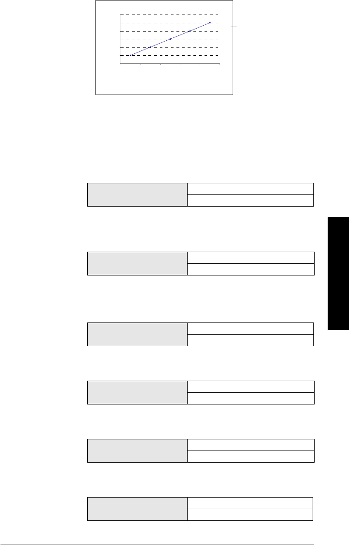
A5E32337685 SITRANS LR260 (PROFIBUS PA) – OPERATING INSTRUCTIONS Page 69
mmmmm
Parameters
2.3.1.8. Output Scale
Scales the Process Variable. The function block parameter OUT SCALE
contains the values of the lower limit and upper limit effective range in
AIFB1 units.
2.3.1.8.1. Lower Value
Defines the operational lower range value of the output value in
AIFB1 units.
2.3.1.8.2. Upper Value
Defines the operational upper range value of the output value in
AIFB1 units.
2.3.1.9. Output Limits
2.3.1.9.1. Lower Limit Alarm (LO LIMIT ALARM)
The setting for the lower alarm limit in AIFB1 units.
2.3.1.9.2. Lower Limit Warning (LO LIMIT WARN)
The setting for the lower warning limit in AIFB1 units.
2.3.1.9.3. Upper Limit Warning (HI LIMIT WARN)
The setting for the upper warning limit in AIFB1 units.
2.3.1.9.4. Upper Limit Alarm (HI LIMIT ALARM)
The setting for the upper alarm limit in AIFB1 units
Values Range: -999.99 to 999.99 m
Default: 0 m
Values Range: -999.99 to 999.99 m
Default: 30 m (dependent on horn type)
Values Range: -999.99 to 999.99 m
Default: -999.99 m
Values Range: -999.99 to 999.99 m
Default: -999.99 m
Values Range: -999.99 to 999.99 m
Default: 999.99 m
Values Range: -999.99 to 999.99 m
Default: 999.99 m
0
1
2
3
4
5
6
12345
Process Value Scale (typical
Input (0 to 100%)
Output Scale
Out (AIFB1)

Page 70 SITRANS LR260 (PROFIBUS PA) – OPERATING INSTRUCTIONS A5E32337685
mmmmm
Parameters
2.3.1.9.5. Limit Hysteresis
Hysteresis is used to adjust the sensitivity of the trigger for alarm
messages. It is used to compensate when a process variable
fluctuates around the same value as a limit. A high level alarm occurs
when a value exceeds an upper limit. The alarm’s status remains
true until the value drops below the limit minus the alarm hysteresis.
The directions are reversed for low limit detection.
Enter a value for the hysteresis here, to be used for all warnings and
alarms. The units are the same as the Output scale, i.e. AIFB1 units.
2.3.1.10. Human Interface
2.3.1.10.1. Decimal Point
The number of digits to display after the decimal point. (The LCD is
limited to displaying two decimal places in Measurement mode. In
SIMATIC PDM up to seven decimal places may be used to display
measured values.)
2.3.2. AIFB2
(See AIFB1: the parameters for AIFB2 are identical.)
2.4. Fail-safe
2.4.1. LOE Timer
Sets the time to elapse in minutes since the last valid reading, before Fail-safe
State activates
Values Range: -999.99 to 999.99 m
Default: 0.5% of output scale range
Options Range: 0, 1, 2, 3, 4, 5, 6, 7
Default: 2
Note: The last valid reading is maintained until the LOE timer expires. After
the timer expires, the reading is set based on Fail-safe Value (see below).
Values Range: 0 to 720 min.
Default: 10.0 min

A5E32337685 SITRANS LR260 (PROFIBUS PA) – OPERATING INSTRUCTIONS Page 71
mmmmm
Parameters
2.4.2. Fail-safe Mode FB1 (FS MODE FB1)
Fail-safe Mode occurs if the status of the input value is bad, or if the device has
been put into Fail-safe mode using Simulation. One of three options can be
selected for the material level to be reported when the LOE timer expires.
2.4.3. Fail-safe Value FB1 (FS VALUE FB1)
Accessible in SIMATIC PDM only after Substitute value is selected in Fail-safe
Mode FB1 (FS MODE FB1)(2.4.2.).
User-defined default for the Output Value, if sensor or sensor electronic fault is
detected. Units are the same as the AIFB1 units.
2.4.4. Fail-safe Mode FB2 (FS MODE FB2)
Fail-safe Mode occurs if the status of the input value is bad, or if the device has
been put into Fail-safe mode using Simulation. One of three options can be
selected for the material level to be reported when the LOE timer expires.
2.4.5. Fail-safe Value FB2 (FS VALUE FB2)
Accessible in SIMATIC PDM only after Substitute value is selected in Fail-safe
Mode FB2 (FS MODE FB2)(2.4.4.).
User-defined default for the Output Value, if sensor or sensor electronic fault is
detected. Units are the same as the AIFB2 units.
Material level to be reported
Options
Substitute value (Default value used as output value).
* Last value (Store last valid output value).
Use bad value (Calculated output value is incorrect).
Values Range: -999.99 to 999.99 m
Default: 0 m
Material level to be reported
Options
Substitute value (Default value used as output value).
* Last value (Store last valid output value).
Use bad value (Calculated output value is incorrect).
Values Range: -999.99 to 999.99 m
Default: 0 m

Page 72 SITRANS LR260 (PROFIBUS PA) – OPERATING INSTRUCTIONS A5E32337685
mmmmm
Parameters
3. Diagnostics
Use these parameters to set up schedules for calibration and maintenance. The device
will track itself based on operating hours instead of a calendar-based schedule, and will
monitor its predicted lifetime.
The maintenance warnings and alarms are communicated via either the Status or
Condensed Status bytes. This information can be integrated into any Asset Management
system. We recommend that you use SIMATIC PCS7 Asset Management Software in
conjunction with SIMATIC PDM.
3.1. Fault Reset
Clears the following fault (known as Acknowledge Fault in PDM.)
To clear a fault using the handheld programmer:
• Enter the fault code number then press RIGHT Arrow.
To clear a fault via SIMATIC PDM:
• Open the menu View – Acknowledge Faults.
• Select the fault to be cleared from the pull-down menu in Extended
Diagnostics.
• Click on Transfer to clear the fault.
3.2. Echo Profile
You can request the current echo profile either via the handheld programmer (see
next page) or via SIMATIC PDM. (For more details see Echo Processing on page
103.)
To request a profile via SIMATIC PDM:
a. Open the menu View – Echo Profile.
b. If desired, press Save.
c. To view the saved profile, open the menu View – Show Echo Profile.
Fault Code Description
S12 Internal Temperature High
Fault Code Description
S3 Device Lifetime Limit 1 (Maintenance Required)
S4 Device Lifetime Limit 2 (Maintenance Demanded)
S6 Sensor Lifetime Limit 1 (Maintenance Required)
S7 Sensor Lifetime Limit 2 (Maintenance Demanded)
S8 Device Service Limit 1 (Maintenance Required)
S9 Device Service Limit 2 (Maintenance Demanded)
S17 Calibration Schedule Limit 1 (Maintenance Required
S18 Calibration Schedule Limit 2 (Maintenance Demanded)
S25 Internal Error (Maintenance Demanded)

A5E32337685 SITRANS LR260 (PROFIBUS PA) – OPERATING INSTRUCTIONS Page 73
mmmmm
Parameters
To request a profile via the handheld programmer:
a. In PROGRAM mode, navigate to ECHO PROFILE (3.2)
b. Press RIGHT arrow to request a profile.
c. In the Profile screen, press UP arrow to select the Transmit icon, and
Right ARROW to update the profile.
d. Press DOWN arrow to select the Exit icon, then Right ARROW to return to
previous menu.
3.3. Measured Values (MEAS. VALUES)
To access the following parameters via SIMATIC PDM, open the menu View – Peak
Values, and click on the appropriate tab.
3.3.1. Min. Measured Value (MIN. MEAS. VALUE)
The minimum recorded Sensor value, defined in Sensor units.
3.3.2. Max. Measured Value (MAX. MEAS. VALUE)
The maximum recorded Sensor value, defined in Sensor units.
3.3.3. Minimum Output Value - AIFB1 (MIN. OUTPUT FB1)
The minimum recorded Output Value from the Analog Input Function Block 1.
3.3.4. Maximum Output Value - AIFB1 (MAX. OUTPUT FB1)
The maximum recorded Output Value from the Analog Input Function Block 1.
3.3.5. Minimum Output Value - AIFB2 (MIN. OUTPUT FB2)
The minimum recorded Output Value from the Analog Input Function Block 2.
3.3.6. Maximum Output Value - AIFB2 (MAX. OUTPUT FB2)
The maximum recorded Output Value from the Analog Input Function Block 2.
3.3.7. Minimum Internal Temperature (MIN. INTERN. TEMP)
Read only. The minimum recorded electronics temperature of the SITRANS
LR260.
3.3.8. Maximum Internal Temperature (MAX. INTERN. TEMP)
Read only. The maximum recorded electronics temperature of the SITRANS
LR260.
transmit icon,
selected
exit icon,
deselected
exit icon, selected
transmit icon, deselected
Distance value
Algorithm selection (First echo)
TVT curve
material
level
Echo confidence
value
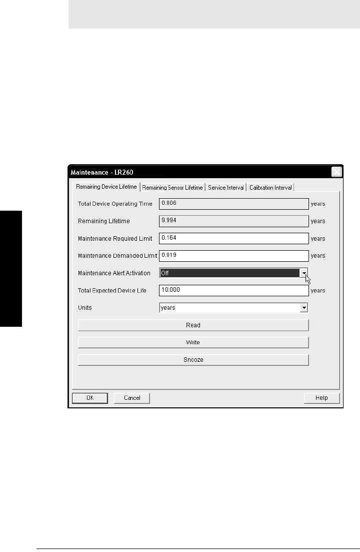
Page 74 SITRANS LR260 (PROFIBUS PA) – OPERATING INSTRUCTIONS A5E32337685
mmmmm
Parameters
3.4. Remaining Device Lifetime (REMAIN. DEV. LIFE)
The Remaining Device/Sensor Lifetime parameters set up schedules for calibration
and maintenance. The device will track itself based on operating hours instead of a
calendar-based schedule, and will monitor its predicted lifetime.
The maintenance warnings and alarms are communicated via either the Status or
Condensed Status bytes. This information can be integrated into any Asset
Management system. We recommend that you use SIMATIC PCS7 Asset
Management Software in conjunction with SIMATIC PDM.
• To access these parameters via SIMATIC PDM open the menu Device –
Maintenance and select the Remaining Device Lifetime tab.
• After modifying values/units as required, click on Write to accept the change,
and Read to view the effect of the change.
• Click on Snooze to add a year to the Total Expected Device Life.
3.4.1. Total Device Operating Time (TOTAL OP. TIME)
Read only. Displays the amount of time the device has been operating in
selected units.
3.4.2. Remaining Device Lifetime (REMAIN LIFETIME)
Read only. Total Expected Device Life less Total Device Operating Time in
selected units.
Note: Performing a reset to Factory Defaults will reset all Maintenance
parameters to their factory defaults.

A5E32337685 SITRANS LR260 (PROFIBUS PA) – OPERATING INSTRUCTIONS Page 75
mmmmm
Parameters
3.4.3. Maintenance Required Limit (MAINT REQ LIMIT)
If the Total Expected Device Life less Total Device Operating Time is equal to or
less than this limit, the device sets Maintenance Required.
a) Open the menu Device – Maintenance, and click on the Remaining Device/
Sensor Lifetime tab.
b) Modify limit values as required.
c) Modify desired values, and click on Write.
d) Click on Read to see the effects of your modification.
e) Click on Snooze to add a year to the Total Expected Device Life.
f) See Maintenance Alert Activation (ALERT ACTIVATION)(3.4.5.) to set the
Alert Activation options.
3.4.4. Maintenance Demanded Limit (MAINT DEM LIMIT)
If the Total Expected Device Life less Total Device Operating Time is equal to or
less than this limit, a Maintenance Demanded status is generated.
a) Open the menu Device – Maintenance, and click on the Remaining Device/
Sensor Lifetime tab.
b) Modify limit values as required.
c) Modify desired values, and click on Write.
d) Click on Read to see the effects of your modification.
e) Click on Snooze to add a year to the Total Expected Device Life.
f) See Maintenance Alert Activation (ALERT ACTIVATION)(3.4.5.) to set the
Alert Activation options.
3.4.5. Maintenance Alert Activation (ALERT ACTIVATION)
Select limits to be activated.
To enable or disable Maintenance Alert Activation via SIMATIC PDM:
a) First set the limit values in Maintenance Required Limit (MAINT REQ
LIMIT)(3.4.3.)/Maintenance Demanded Limit (MAINT DEM LIMIT)(3.4.4.)
b) Modify desired values, and click on Write.
c) Click on Read to see the effects of your modification.
d) Click on Snooze to add a year to the Total Expected Device Life.
e) Select the desired Alert Activation option.
Values Range: 0 to 20 years
Default: 0.164 years
Values Range: 0 to 20 years
Default: 0.019 years
Values
Warning Limit 1 (Maintenance Required Limit)
Warning Limit 2 (Maintenance Demanded Limit)
Warning Limits 1 and 2 (Maintenance Required and
Maintenance Demanded Limits)
*OFF
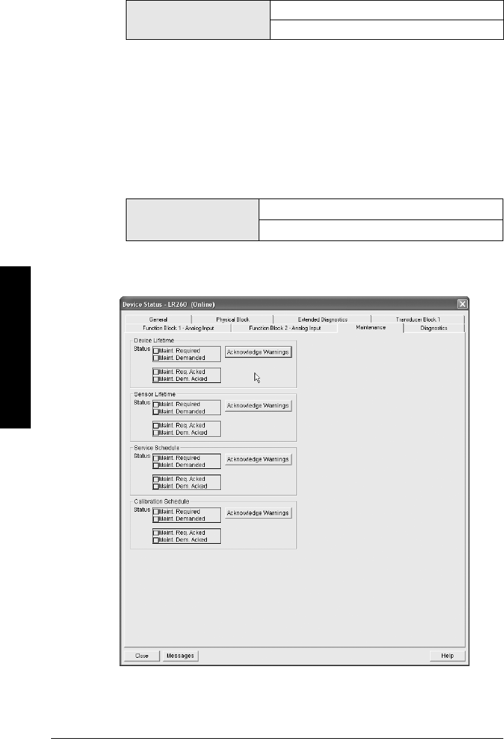
Page 76 SITRANS LR260 (PROFIBUS PA) – OPERATING INSTRUCTIONS A5E32337685
mmmmm
Parameters
3.4.6. Total Expected Device Life (TOTAL EXP. LIFE)
The device tries to predict its overall lifetime. The factory default can be reset
by the user.
To modify the value via SIMATIC PDM:
a) Open the menu Device – Maintenance and click on Remaining Device
Lifetime.
b) Modify desired values, and click on Write.
c) Click on Read to see the effects of your modification.
d) Click on Snooze to add a year to the Total Expected Device Life.
3.4.7. Maintenance Status (MAINT STAT)
Displays the status of the Maintenance Alerts.
To view via SIMATIC PDM, open the menu View - Device Status, click on the
Maintenance tab, and check the Device Lifetime Status window.
Values Range: 0 to 20 years
Default: 10.00 years
Options (view only) Maintenance Required Alert active
Maintenance Demanded Alert Active
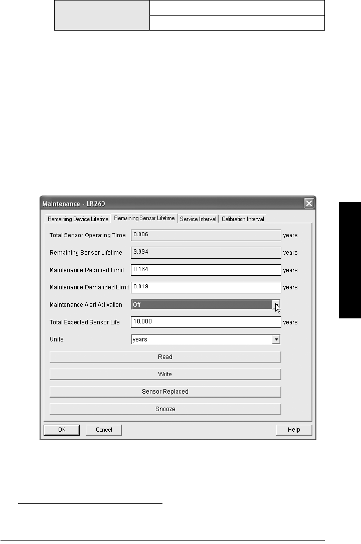
A5E32337685 SITRANS LR260 (PROFIBUS PA) – OPERATING INSTRUCTIONS Page 77
mmmmm
Parameters
3.4.8. Acknowledge Status (ACK STATUS)
Displays the status of the Maintenance Alerts that have been acknowledged.
3.4.9. Acknowledge (ACK)
Allows you to acknowledge either a Maintenance Required or a Maintenance
Demanded alert.
To acknowledge an alert via SIMATIC PDM:
a) Open the menu View – Device Status and click on the Maintenance tab.
b) In the Device Lifetime section, click on Acknowledge Warnings.
3.5. Remaining Sensor Lifetime (REMAIN SENS. LIFE)1)
The device monitors the predicted lifetime of the sensor (the components exposed to
the vessel environment).
To access these parameters via SIMATIC PDM, open the menu Device –
Maintenance and select the Remaining Sensor Lifetime tab.
3.5.1. Total Sensor Operating Time (SENS OP. TIME)
Read only. Displays the amount of time the sensor has been operating.
Can be reset to zero via the handheld programmer (after performing a service).
Options (view only) Maintenance Required Alert acknowledged.
Maintenance Demanded Alert acknowledged.
1) In device, Maintenance parameters are displayed in years. In SIMATIC PDM, mainte-
nance parameter units are user selectable.

Page 78 SITRANS LR260 (PROFIBUS PA) – OPERATING INSTRUCTIONS A5E32337685
mmmmm
Parameters
3.5.2. Remaining Sensor Lifetime (REMAIN LIFETIME)
Read only. The sum of Total Expected Sensor Life less Total Sensor Operating
Time.
3.5.3. Maintenance Required Limit (MAINT REQ LIMIT)
If the Total Expected Sensor Life less Total Sensor Operating Time is equal to
or less than this limit, a Maintenance Required status is generated.
To modify the value via SIMATIC PDM:
a) Modify limit values as required.
b) Modify desired values, and click on Write.
c) Click on Read to see the effects of your modification.
d) Click on Snooze to add a year to the Total Expected Device Life.
e) Enable Maintenance Alert Activation (ALERT ACTIVATION)(3.5.5.) to set
the Alert Activation options.
3.5.4. Maintenance Demanded Limit (MAINT. DEM. LIMIT)
If the Total Expected Sensor Life less Total Sensor Operating Time is equal to
or less than this limit, a Maintenance Demanded status is generated.
To modify the value via SIMATIC PDM:
a) Modify limit values as required
b) Modify desired values, and click on Write.
c) Click on Read to see the effects of your modification.
d) Click on Snooze to add a year to the Total Expected Device Life.
e) Enable Maintenance Alert Activation (ALERT ACTIVATION)(3.5.5.) to set
the Alert Activation options.
3.5.5. Maintenance Alert Activation (ALERT ACTIVATION)
Select limits to be activated.
To enable or disable Maintenance Alert Activation via SIMATIC PDM:
a) First set the limit values in Maintenance Required Limit (MAINT REQ
LIMIT)(3.5.3.) and Maintenance Demanded Limit (MAINT. DEM.
LIMIT)(3.5.4.).
b) Modify desired values, and click on Write.
c) Click on Read to see the effects of your modification.
d) Click on Snooze to add a year to the Total Expected Device Life.
Values Range: 0 to 20 years
Default: 0.164 years
Values Range: 0 to 20 years
Default: 0.019 years
Values
Warning Limit 1 (Maintenance Required Limit)
Warning Limit 2 (Maintenance Demanded Limit)
Warning Limits 1 and 2 (Maintenance Required and
Maintenance Demanded Limits)
*OFF
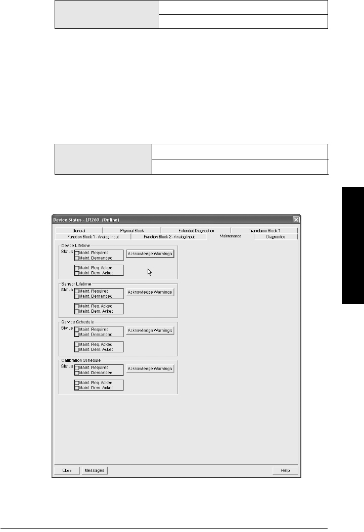
A5E32337685 SITRANS LR260 (PROFIBUS PA) – OPERATING INSTRUCTIONS Page 79
mmmmm
Parameters
e) Select the desired Alert Activation option.
3.5.6. Total Expected Sensor Life (TOTAL EXP. LIFE)
The device tries to predict its overall lifetime. You can reset the factory default.
To modify the value via SIMATIC PDM:
a) Open the menu Device – Maintenance and click on Remaining Sensor
Lifetime.
b) Modify the value/units as desired(or click on Snooze to add a year to the
current value) then click on Write to accept the change.
c) Click on Read to view the effect of the modification.
3.5.7. Maintenance Status (MAINT STAT)
Displays the status of the Maintenance Alerts.
To view via SIMATIC PDM open the menu View - Device Status, click on the
Maintenance tab, and check the Sensor Lifetime Status window.
Values Range: 0 to 20 years
Default: 10.00 years
Options (view only) Maintenance Required Alert active
Maintenance Demanded Alert Active

Page 80 SITRANS LR260 (PROFIBUS PA) – OPERATING INSTRUCTIONS A5E32337685
mmmmm
Parameters
3.5.8. Acknowledge Status (ACK STATUS)
Displays the status of the Maintenance Alerts that have been acknowledged.
3.5.9. Acknowledge (ACK)
Allows you to acknowledge either a Maintenance Required or a Maintenance
Demanded alert.
To acknowledge an alert via SIMATIC PDM:
a) Open the menu View – Device Status and click on the Maintenance tab.
b) In the Sensor Lifetime section, click on Acknowledge Warnings.
3.6. Condensed Status Setup (COND. STAT. SETUP)
When Condensed Status Mode (COND. STAT. MODE)(3.6.1.) is enabled, you can
select the level of severity of errors, and tailor a device response appropriate for your
particular process.
•In Event Index(3.7.1.), you can select a particular event or error by means of its
index number.
•In Event Status (EVENT. STAT)(3.7.2.), you can assign a status to the selected
event.
•In Event Diagnosis (EVENT DIAG.)(3.7.3.), you can assign a diagnosis to the
selected event.
3.6.1. Condensed Status Mode (COND. STAT. MODE)
Select Yes or No to enable/disable Condensed Mode.
3.6.2. Features supported (View only) (FEAT. SUPPORTED)
Features supported are:
• Condensed Diagnostics
• Extended Diagnostics
• Application Relationships
3.6.3. Features enabled (View only) (FEAT. ENABLED)
Lists those features that have been enabled.
Options (view only) Maintenance Required Alert acknowledged.
Maintenance Demanded Alert acknowledged.
Note: When cyclic communication is in progress, Condensed Status Mode
cannot be changed.
Options No (disabled)
*Yes (enabled)

A5E32337685 SITRANS LR260 (PROFIBUS PA) – OPERATING INSTRUCTIONS Page 81
mmmmm
Parameters
3.7. Condensed Status
3.7.1. Event Index
The numeric component of the Event Code for a Condensed Status event. Use
the index number to identify a particular event in the list below.
For example:
Event Code for Loss of Echo = S0
Event Index = 0
To select a particular event via the handheld programmer:
a) Go to Condensed Status Mode (COND. STAT. MODE)(3.6.1.) and select Yes
to enable Condensed Mode.
b) Go to Event Index(3.7.1.) and enter the event index number corresponding
to the event.
c) Go to Event Status (EVENT. STAT)(3.7.2.) and choose a Status option.
d) Go to Event Diagnosis (EVENT DIAG.)(3.7.3.) and choose a Diagnosis
option.
Event Index Event Code Event Descriptiona)
a) See
General Fault Codes
on page 95 for the meaning of each event.
0 S0 Loss of Echo
2S2 No Tech Power
10 S10 Level Transducer Block (LTB) Scale
11 S11 Internal Temperature Sensor
12 S12 Internal Temperature High
14 S14 AIFB1 PV Range
15 S15 AIFB2 PV Range
25 S25 Internal Device Error
28 S28 Memory RAM
29 S29 EEPROM damaged.
31 S31 Memory Flash
33 S33 Internal Temperature Calibration
34 S34 Velocity Calibration
35 S35 Receiver Init Calibration
36 S36 Receiver Calibration
37 S37 Technology Module Calibration
38 S38 Technology Module Ramp

Page 82 SITRANS LR260 (PROFIBUS PA) – OPERATING INSTRUCTIONS A5E32337685
mmmmm
Parameters
To select a particular event via SIMATIC PDM:
a) Go to Diagnostics > Condensed Status Setup > Condensed Status Mode
and select Yes to enable Condensed Mode.
b) Go to Diagnostics > Condensed Status.
c) For each event, you can select either the Status or the Diagnosis line, then
choose a Status or Diagnosis option from the associated pull-down menu.
3.7.2. Event Status (EVENT. STAT)
Event Status allows you to assign one of the status options listed below, to any
of the events listed in Event Index(3.7.1.). This allows you to tailor a device
response appropriate for your particular process.
(Event Status affects
Condensed Status
1)
).
To assign a status to a particular event via the handheld programmer:
a) Go to Condensed Status Mode (COND. STAT. MODE)(3.6.1.) and select Yes
to enable Condensed Mode.
b) Go to Event Index(3.7.1.) and enter the event index number corresponding
to a particular event.
c) Go to Event Status (EVENT. STAT)(3.7.2.) and choose a Status option from
the table above.
d) Go to Event Diagnosis (EVENT DIAG.)(3.7.3.) and choose a Diagnosis
option.
To assign a status to a particular event via SIMATIC PDM:
a) Go to Level Meter > Diagnostics > Condensed Status Setup, select Yes to
enable Condensed Status Mode.
b) Go to Level Meter > Diagnostics > Condensed Status.
c) Select the Status line for the selected Event, then choose a Diagnosis
option from the associated pull-down menu.
Event Status Options
Good
Good: maintenance required
Good: maintenance demanded
Uncertain: maintenance demanded
*Bad: maintenance alarm
Uncertain: process related, no maintenance
Bad: process related, no maintenance
Bad: function check, local override
Good: function check
1) See
Condensed Status
on page 122 for more detail.

A5E32337685 SITRANS LR260 (PROFIBUS PA) – OPERATING INSTRUCTIONS Page 83
mmmmm
Parameters
3.7.3. Event Diagnosis (EVENT DIAG.)
Allows you to assign one of the diagnostic options listed below to any of the
events listed in Event Index(3.7.1.). This allows you to tailor a device response
appropriate for your particular process.(Event Diagnosis affects Condensed
Acyclic Diagnostics and Cyclic Extended Diagnostics
1)
).
To assign a diagnosis to a particular event via the handheld programmer:
a) Go to Condensed Status Mode (COND. STAT. MODE)(3.6.1.) and select Yes
to enable Condensed Mode.
b) Go to Event Index(3.7.1.) and enter the event index number corresponding
to a particular event.
c) Go to Event Status (EVENT. STAT)(3.7.2.) and choose a Status option.
d) Go to Event Diagnosis (EVENT DIAG.)(3.7.3.) and choose a Diagnosis option
from the table above.
To assign a status to a particular event via SIMATIC PDM:
a) Go to Level Meter > Diagnostics > Condensed Status Setup, and select
Yes to enable Condensed Status Mode.
b) Go to Level Meter > Diagnostics > Condensed Status.
c) Select the Diagnosis line for the selected Event, then choose a Diagnosis
option from the associated pull-down menu.
Event Diagnosis Options
Status OK
Maintenance Required
Maintenance Demanded
* Maintenance alarm
Invalid process condition
Function check or simulation
1) See
Condensed Mode Diagnosis
on page 126 for more detail.

Page 84 SITRANS LR260 (PROFIBUS PA) – OPERATING INSTRUCTIONS A5E32337685
mmmmm
Parameters
4. Service
4.1. Device Reset
To access via SIMATIC PDM, open the menu Device – Device Reset. For more detail
see
Device Reset
on page 47.
To perform a reset via the handheld programmer:
a. Press RIGHT Arrow to open Edit Mode then scroll down to the desired Reset
option and press RIGHT Arrow to select it.
b. Press LEFT Arrow to exit.
4.2. LCD Fast Mode
Enables a faster rate of measurement from the device by disabling most of the
display area. Only the bar graph will be refreshed when LCD Fast Mode is set to ON.
When Fast Mode is set to ON, there is a delay of 30 minutes with no pressed buttons
before actions result.
Note: Following a Factory Reset, some degree of reprogramming may be required,
depending on the option chosen below.
Reset Options Result
Factory Defaultsa)
a) Differences between Factory Defaults and Standard Defaults:
Factory Reset modifies the functional block outputs to measure distance in
meters and to be scaled based on Low Calibration Point.
Resets all parameters to the manufacturer’s default
settings with the following exceptions:
• device addresses are not reset
• Lock and Unlock values are not reset
• the learned TVT curve is not lost
• Description, Tag, Message, and Installation Date (in
SIMATIC PDM) are not reset
Standard Defaultsa
Resets all parameters excluding device addresses,
Description, Message, and Installation Date to the
PROFIBUS default settings
Informational Resets parameter Tag
Functional Resets parameters that control device behavior and
functionality (such as calibration points)
Warm Start Has the same effect as re-cycling power to the device
Reset Device Address
to 126
• Resets the PROFIBUS device address to 126
• If the address lock was on, will disable the lock. (See
Resetting the PROFIBUS address to 126: on page 120
for details.)
Note: Affects Measurement mode only: has no effect on Navigation mode.
Values ON or OFF
Default: OFF

A5E32337685 SITRANS LR260 (PROFIBUS PA) – OPERATING INSTRUCTIONS Page 85
mmmmm
Parameters
4.3. LCD Contrast
The factory setting is for optimum visibility at room temperature and in average light
conditions. Extremes of temperature will lessen the contrast.
Adjust the value to improve visibility in different temperatures and luminosity. Change
the LCD contrast in small steps to ensure you can continue to read the display and to
prevent viewing difficulties.
4.4. PROFIBUS Ident Number (PROFIBUS IDENT)
Identifies the device on the network. The Ident Number must match that in the GSD
file (the GSD file provides information on the device to the master).
4.5. Powered Hours
View only. Number of hours the unit has been powered up since manufacture.
To view via SIMATIC PDM, open the menu View – Wear.
4.6. Power-on Resets
View only. The number of power cycles that have occurred since manufacture.
To view via SIMATIC PDM, open the menu View – Wear.
4.17. Service Interval
Allows for scheduling of service inspections.
To access these parameters via SIMATIC PDM, open the menu Device –
Maintenance and click on the Service Schedule tab.
4.17.1. Time Last Serviced (TIME LAST SERV)
View only. Time elapsed since device was last serviced.
Can be reset to zero via the handheld programmer (after performing a service).
4.17.2. Remaining Lifetime (REMAIN LIFETIME)
View only. The sum of Total Service Interval less Time Last Serviced.
4.17.3. Maintenance Required Limit (MAINT REQ LIMIT)
If Remaining Lifetime is equal to or less than this limit, a Maintenance Required
status is generated.
Values Range: 0 (High contrast) to 20 (Low contrast).
Default: Matches factory calibration for best visual contrast.
Options
STD PROFILE Standard Profile (uses generic GSD for 2 AIFB
[ident # = 0x9701]
* MANUFACTURER
Manufacturer-specific (uses Siemens EDD and GSD
file, which identifies the LR260 [PROFIBUS PA])
[ident # = 0x8162]
STD – AIFB 1
ONL.
Standard Profile AIFB 1 only (uses generic GSD for 1
AIFB) [ident # = 0x9700]
Values Range: 0 to 20 years
Default: 0.164 years

Page 86 SITRANS LR260 (PROFIBUS PA) – OPERATING INSTRUCTIONS A5E32337685
mmmmm
Parameters
4.17.4. Maintenance Demanded Limit (MAINT DEM. LIMIT)
If Remaining Lifetime is equal to or less than this limit, a Maintenance
Demanded status is generated.
4.17.5. Alert Activation
Select limits to be activated.
4.17.6. Service Interval
Set time between scheduled service inspections.
4.17.7. Maintenance Status (MAINT STAT)
Displays the status of the Maintenance Alerts.
Open the menu View – Device Status and click on the Maintenance tab.
4.17.8. Acknowledge Status (ACK STATUS)
Displays the status of the Maintenance Alerts that have been acknowledged.
4.17.9. Acknowledge (ACK)
Allows you to acknowledge either a Maintenance Required or a Maintenance
Demanded alert.
In SIMATIC PDM:
a) Open the menu View – Device Status and click on the Maintenance tab.
b) Click on the appropriate Acknowledge Warnings button then click on
Close.
Values Range: 0 to 20 years
Default: 0.019 years
Options
* Timer off
On - no limits
On - limit 1
On - limits 1 - 2
On - limit 2
Values Range: 0 to 20 years
Default: 1.0 year
Options (view only) Maintenance Required Alert active
Maintenance Demanded Alert Active
Options (view only) Maintenance Required Alert acknowledged
Maintenance Demanded Alert acknowledged

A5E32337685 SITRANS LR260 (PROFIBUS PA) – OPERATING INSTRUCTIONS Page 87
mmmmm
Parameters
4.18. Calibration Interval (CALIB INTERVAL)
Allows you to schedule calibration.
To access these parameters via SIMATIC PDM, open the menu Device –Maintenance
and click on the Calibration Schedule tab.
4.18.1. Time Last Calibrated (TIME LAST CAL.)
View only: time elapsed since device was last calibrated.
Can be reset to zero via the handheld programmer (after performing a service).
4.18.2. Remaining Lifetime (REMAIN LIFETIME)
View only. The sum of Total Calibration Interval less Time Last Calibrated.
4.18.3. Maintenance Required Limit (MAINT REQ LIMIT)
If Remaining Lifetime is equal to or less than this limit, a Maintenance Required
status is generated.
4.18.4. Maintenance Demanded Limit (MAINT DEM LIMIT)
If Remaining Lifetime is equal to or less than this limit, a Maintenance
Demanded status is generated.
4.18.5. Alert Activation
Select limits to be activated.
4.18.6. Total Calibration Interval (TOTAL CALIB. INTRV)
Set time between scheduled calibrations.
4.18.7. Maintenance Status (MAINT STAT)
Displays the status of the Maintenance Alerts
In SIMATIC PDM, open the menu View – Device Status and click on the
Maintenance tab
.
Values Range: 0 to 20 years
Default: 0.164 years
Values Range: 0 to 20 years
Default: 0.019 years
Options
* Timer off
On - no limits
On - limit 1
On - limits 1 - 2
On - limit 2
Values Range: 0 to 20 years
Default: 1.0 year
Options (view
only)
Maintenance Required Alert active
Maintenance Demanded Alert Active

Page 88 SITRANS LR260 (PROFIBUS PA) – OPERATING INSTRUCTIONS A5E32337685
mmmmm
Parameters
4.18.8. Acknowledge Status (ACK STAT)
Displays the status of the Maintenance Alerts that have been acknowledged.
In SIMATIC PDM, open the menu View – Device Status and click on the
Maintenance tab
.
4.18.9. Acknowledge (ACK)
Allows you to acknowledge either a Maintenance Required or a Maintenance
Demanded alert.
In SIMATIC PDM:
a) Open the menu View – Device Status and click on the Maintenance tab.
b) Click on the appropriate Acknowledge Warnings button then click on
Close.
5. Communication
5.1. Device Address
Sets the unique address of the device on the network (also called PROFIBUS
address).
To change Device Address via SIMATIC PDM:
a) Open the menu Device – Set Address.
b) Enter value in New Address field and click on Assign Address button.
To change Device Address via the handheld programmer:
See
Device Address
on page 35 for details.
5.2. Remote Lockout
Enables or disables programming via the network and PDM.
6. Security
6.1. Write Locking
Prevents any changes to parameters via PDM or the hand-held programmer.
In SIMATIC PDM, open the menu Device – Write Locking, and select On or Off.
Options (view
only)
Maintenance Required Alert acknowledged
Maintenance Demanded Alert acknowledged
Note: The address can be changed and locked from a remote master. See
Resetting
the PROFIBUS address to 126:
on page 120 for details on disabling the address lock.
Values 0 - 126. Default: 126
Options * Off (Remote operation enabled)
On (Remote operation disabled)
Hand-held
programmer
Values
2457 (unlock value) Off (enables programming)
any other value On (disables programming)

A5E32337685 SITRANS LR260 (PROFIBUS PA) – OPERATING INSTRUCTIONS Page 89
mmmmm
Parameters
7. Language
Selects the language to be used on the LCD.
Options
*English
German
French
Spanish

Page 90 SITRANS LR260 (PROFIBUS PA) – OPERATING INSTRUCTIONS A5E32337685
mmmmm
Parameters
Notes

A5E32337685 SITRANS LR260(PROFIBUS PA) – OPERATING INSTRUCTIONS Page 91
mmmmm
A: Parameter List
Appendix A: Alphabetical Parameter
List
Note: Maintenance Parameters are not listed below. See
Remaining Device Lifetime
(REMAIN. DEV. LIFE) (3.4.) on page 74
,
Remaining Sensor Lifetime (REMAIN SENS. LIFE)
(3.5.) on page 77
,
Service Interval (4.17.) on page 85
, and
Calibration Interval (CALIB
INTERVAL) (4.18.) on page 87
for those parameters.
Parameter Name (Parameter Number) Page Number
Algorithm (2.2.3.1.1.) 56
Auto False Echo Suppression (AUTO ECHO SUPP) (2.2.4.3.) 62
Auto Suppression Range (AUTO SUPP RANGE) (2.2.4.4.) 63
Echo Confidence (2.2.3.6.1.) 61
Device Address (5.1.) 88
Device Reset (4.1.) 84
Echo Lock (2.2.3.2.1.) 58
Echo Marker (2.2.3.1.4.) 57
Echo Profile (3.2.) 72
Echo Threshold (2.2.3.1.2.) 57
Empty rate (EMPTY RATE/MIN) (2.2.6.3.) 66
Fail-safe Mode FB1 (FS MODE FB1) (2.4.2.) 71
Fail-safe Mode FB2 (FS MODE FB2) (2.4.4.) 71
Fail-safe Value FB1 (FS VALUE FB1) (2.4.3.) 71
Fail-safe Value FB2 (FS VALUE FB2) (2.4.5.) 71
Far Range (2.2.3.5.2.) 60
Fill Rate (FILL RATE/MIN) (2.2.6.2.) 65
Filter Time Constant (FILTER TIME CONST) (2.3.1.4.) 67
Firmware Revision (FIRMWARE REV.) (2.1.4.) 54
Hardware Revision (HARDWARE REV.) (2.1.6.) 54
High Calibration Pt. (HIGH CALIB. PT.) (2.2.1.4.) 55
Language (7.) 89
LCD Contrast (4.3.) 85
LCD Fast Mode (4.2.) 84
Level Offset (2.2.1.9.) 55
Loader Revision (LOADER REV.) (2.1.5.) 54
LOE Timer (2.4.1.) 70
Low Calibration Pt. (LOW CALIB. PT.) (2.2.1.3.) 55
Maximum Internal Temperature (MAX. INTERN. TEMP) (3.3.8.) 73
Minimum Internal Temperature (MIN. INTERN. TEMP) (3.3.7.) 73
Narrow Echo Filter (NARROW ECHO FIL.) (2.2.3.3.2.) 59

Page 92 SITRANS LR260 (PROFIBUS PA) – OPERATING INSTRUCTIONS A5E32337685
mmmmm
A: Parameter List
Near Range (2.2.3.5.1.) 60
Noise (2.2.3.6.) 61
Position (2.2.3.1.3.) 57
Powered Hours (4.5.) 85
Power-on Resets (4.6.) 85
PROFIBUS Ident Number (PROFIBUS IDENT) (4.4.) 85
Remote Lockout (5.2.) 88
Response Rate (2.2.6.1.) 65
Sensor Offset (2.2.1.10.) 56
Sensor Units (2.2.1.2.) 54
Echo Strength (2.2.3.6.2.) 61
Temperature Units (TEMP UNITS) (2.2.1.11.) 56
TVT Hover Level (2.2.4.2.) 62
TVT Type (2.2.4.1.) 61
Unit (Level) (2.2.1.6.) 55
Window (2.2.3.2.4.) 59
Write Locking (6.1.) 88
Parameter Name (Parameter Number) Page Number

A5E32337685 SITRANS LR260 (PROFIBUS PA) – OPERATING INSTRUCTIONS Page 93
mmmmm
B: Troubleshooting
Appendix B: Troubleshooting
1. Check the following:
• There is power at the instrument.
• The LCD shows the relevant data you are expecting.
• Check whether any fault codes are being displayed (see
Acyclic Extended
Diagnostics (General Fault Codes)
on page 127 for a detailed list).
• The device can be programmed using the hand-held programmer.
2. Verify that the wiring connections are correct.
3. Check the PROFIBUS address and make sure all devices are at unique PROFIBUS
addresses.
4. If the device cannot be programmed via the hand-held programmer, make sure Write
Locking (6.1.) on page 88 is disabled.
5. If you try to set a SITRANS LR260 parameter via remote communications, but the
parameter remains unchanged, check the following parameters:
•Remote Lockout (5.2.) on page 88 should be disabled
•Write Locking (6.1.) on page 88 should be disabled
•Resetting the PROFIBUS address to 126: on page 120 on how to disable an
address lock
6. If you continue to experience problems, go to our website at:
www.siemens.com/processautomation, and check the FAQs for SITRANS LR260, or
contact your Siemens Milltronics representative.
7. If the PLC value equals the display value, but does not correspond to actual material
level, either:
• scaling in AIFB1 is incorrect, or
• High Calibration Point is incorrectly entered, or
• the wrong echo is being selected.
8. If the PLC value is not equal to the displayed value (regardless of actual material
level), either:
• you may not be looking at the right spot in the PLC, or
• you may have programmed scaling into the PLC, instead of leaving all scaling to
be performed in the LR260, or
• the PLC may not be communicating with the LR260. Check the network to verify
that you are communicating.
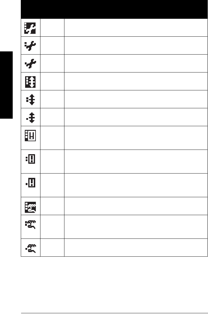
Page 94 SITRANS LR260 (PROFIBUS PA) – OPERATING INSTRUCTIONS A5E32337685
mmmmm
B: Troubleshooting
Device Status Icons
Icon Priority
Level Meaning
1 • Maintenance alarm
• Measurement values are not valid
2 • Maintenance warning: maintenance demanded immediately
• Measured signal still valid
3 • Maintenance required
• Measured signal still valid
1 • Process value has reached an alarm limit
2 • Process value has reached a warning limit
3 • Process value has reached a tolerance limit
1 • Configuration error
• Device will not work because one or more parameters/
components is incorrectly configured
2 • Configuration warning
• Device can work but one or more parameters/components is
incorrectly configured
3 • Configuration changed
• Device parameterization not consistent with parameterization in
project. Look for info text.
1 • Manual operation (local override)
• Communication is good; device is in manual mode.
2 • Simulation or substitute value
• Communication is good; device is in simulation mode or works
with substitute values.
3 • Out of operation
• Communication is good; device is out of action.

A5E32337685 SITRANS LR260 (PROFIBUS PA) – OPERATING INSTRUCTIONS Page 95
mmmmm
B: Troubleshooting
General Fault Codes
• Data exchanged
• No data exchange
• Write access enabled
• Write access disabled
Notes:
• If more than one fault is present, the device status indicator and text for each fault
alternate at 2 second intervals.
• Some faults cause the device to go to Fail-safe mode (Fault 52). These are indicated with
an asterisk (*).
General Fault Codes
Code /
Icon Meaning Corrective Action
S: 0 * The device was unable to get a mea-
surement within the Fail-safe LOE
Timer period. Possible causes: faulty
installation, antenna material
buildup, foaming/other adverse pro-
cess conditions, invalid calibration
range.
Ensure installation details are cor-
rect. Ensure no antenna material
buildup. Clean if necessary. Adjust
process conditions to minimize foam
or other adverse conditions. Correct
range calibration. If fault persists,
contact your local Siemens repre-
sentative.
S: 2 * Unable to collect profile because of
a power condition that is outside of
the operating range of the device.
Repair required: contact your local
Siemens representative.
S: 3 Device is nearing its lifetime limit
according to the value set in Mainte-
nance Required Limit.
Replacement is recommended.
S: 4 Device is nearing its lifetime limit
according to the value set in Mainte-
nance Demanded Limit.
Replacement is recommended.
Icon Priority
Level Meaning (cont’d)

Page 96 SITRANS LR260 (PROFIBUS PA) – OPERATING INSTRUCTIONS A5E32337685
mmmmm
B: Troubleshooting
S: 6 Sensor is nearing its lifetime limit
according to the value set in Mainte-
nance Required Limit.
Replacement is recommended.
S: 7 Sensor is nearing its lifetime limit
according to the value set in Mainte-
nance Demanded Limit.
Replacement is recommended.
S: 8 Service interval as defined in Main-
tenance Required Limit has expired.
Perform service.
S: 9 Service interval as defined in Main-
tenance Demanded Limit has
expired.
Perform service.
S: 10 Input parameters High Calibration
Point and Low Calibration Point are
the same.
Check calibration settings of device.
Ensure settings for High Calibration
Point and Low Calibration Point are
different.
S: 11 Internal temperature sensor failure. Repair required: contact your local
Siemens representative.
S: 12 Internal temperature of device has
exceeded specifications: it is operat-
ing outside its temperature range.
Relocate device and/or lower pro-
cess temperature enough to cool
device. Inspect for heat-related
damage and contact your local Sie-
mens representative if repair is
required.
Fault code will persist until a manual
reset is performed using PDM or the
LCD interface.
S:14 Upper and Lower input values (Pro-
cess Value Scale) for AIFB1 are the
same.
Check configuration for AIFB1.
Ensure that Upper Value and Lower
Value (Process Value Scale) are not
the same.
General Fault Codes (cont’d) (cont’d)
Code /
Icon Meaning Corrective Action

A5E32337685 SITRANS LR260 (PROFIBUS PA) – OPERATING INSTRUCTIONS Page 97
mmmmm
B: Troubleshooting
S: 15 Upper and Lower input values (Pro-
cess Value Scale) for AIFB2 are the
same.
Check configuration for AIFB2.
Ensure that Upper Value and Lower
Value (Process Value Scale) are not
the same.
S: 17 Calibration interval as defined in
Maintenance Required Limit has
expired.
Perform calibration.
S: 18 Calibration interval as defined in
Maintenance Demanded Limit has
expired.
Perform calibration.
S: 25 Internal device error. Reset power. If fault persists, con-
tact your local Siemens representa-
tive.
S: 28 * Internal device failure caused by a
RAM memory error.
Repair required: contact your local
Siemens representative.
S: 29 * EEPROM damaged. Repair required: contact your local
Siemens representative.
S: 31 * Flash error. Repair required: contact your local
Siemens representative.
S: 32 *IDENT number conflict Ensure value of the Ident number
selector is correct for the network
configuration. If it is correct, the
device needs to be re-parameterized
by the PLC.
S: 33 * Factory calibration for the internal
temperature sensor has been lost.
Repair required: contact your local
Siemens representative.
General Fault Codes (cont’d) (cont’d)
Code /
Icon Meaning Corrective Action

Page 98 SITRANS LR260 (PROFIBUS PA) – OPERATING INSTRUCTIONS A5E32337685
mmmmm
B: Troubleshooting
S: 34 * Factory calibration for the device
has been lost.
Repair required: contact your local
Siemens representative.
S: 35 * Factory calibration for the device
has been lost.
Repair required: contact your local
Siemens representative.
S: 36 * Unable to start microwave module. Cycle power. If fault persists, contact
your local Siemens representative.
S: 37 * Measurement hardware problem. Cycle power. If fault persists, contact
your local Siemens representative.
S: 38 * Microwave module hardware fail-
ure: unable to calculate distance
measurement.
Cycle power. If fault persists, contact
your local Siemens representative:
repair required.
S: 43 * Factory calibration for the radar
receiver has been lost.
Repair required: contact your local
Siemens representative.
S: 64 *SPC42 Access Error Cycle power. If fault persists, contact
your local Siemens representative.
General Fault Codes (cont’d) (cont’d)
Code /
Icon Meaning Corrective Action

A5E32337685 SITRANS LR260 (PROFIBUS PA) – OPERATING INSTRUCTIONS Page 99
mmmmm
B: Troubleshooting
Operation Troubleshooting
Operating symptoms, probable causes, and resolutions.
Symptom Cause Action
Display shows
S: 0 LOE
level or target is out of
range
• check specifications
• check Low Calibration Point (LOW
CALIB. PT.) (1.5.)
• increase Echo Confidence (2.2.3.6.1.)
Display shows
S: 0 LOE
material build-up on
antenna
• clean the antenna
• re-locate SITRANS LR260
Display shows
S: 0 LOE
location or aiming:
• poor installation
• flange not level
• check to ensure nozzle is vertical
•use Auto False Echo Suppression
(AUTO ECHO SUPP) (2.2.4.3.) and
check Auto Suppression Range
(AUTO SUPP RANGE) (2.2.4.4.) to
ensure nozzle protrudes from end of
vessel nozzle.
Display shows
S: 0 LOE
antenna malfunction:
• temperature too high
• physical damage
• check Maximum Internal
Temperature (MAX. INTERN. TEMP)
(3.3.8.)
• set Algorithm (2.2.3.1.1.) to tF
(trueFirst echo)
•relocate
Reading does not
change, but the level
does
SITRANS LR260 process-
ing wrong echo, i.e. vessel
wall, or structural member
• re-locate SITRANS LR260
• ensure nozzle protrudes 10 mm min.
• rotate instrument 90°
•use Auto False Echo Suppression
(AUTO ECHO SUPP) (2.2.4.3.) and
Auto Suppression Range (AUTO
SUPP RANGE) (2.2.4.4.)
Measurement is con-
sistently off by a con-
stant amount
• setting for Low
Calibration Pt. (LOW
CALIB. PT.) (2.2.1.3.) not
correct
• setting for Sensor Offset
(2. 2.1.10. ) not correct
• check distance from sensor
reference point to Low Calibration
Pt. (LOW CALIB. PT.) (2.2.1.3.)
• check Sensor Offset (2.2.1.10.)
Screen blank
power error • check nameplate rating against
voltage supply
• check power wiring or source

Page 100 SITRANS LR260 (PROFIBUS PA) – OPERATING INSTRUCTIONS A5E32337685
mmmmm
B: Troubleshooting
Reading erratic echo confidence weak • refer to Echo Confidence (2.2.3.6.1.)
•use Auto False Echo Suppression
(AUTO ECHO SUPP) (2.2.4.3.) and
Auto Suppression Range (AUTO
SUPP RANGE) (2.2.4.4.)
• use foam deflector
liquid surface vortexed • decrease Fill Rate (FILL RATE/MIN)
(2.2.6.2.)
• increase confidence threshold in
Echo Threshold (2.2.3.1.2.)
material filling • re-locate SITRANS LR260
Reading response
slow
Fill Rate (FILL RATE/MIN)
(2.2.6.2.) setting is incorrect
• increase measurement response if
possible
Reads correctly but
occasionally reads
high when vessel is
not full
• detecting close range
echo
• build up near top of
vessel or nozzle
• nozzle problem
• clean the antenna
•use Auto False Echo Suppression
(AUTO ECHO SUPP) (2.2.4.3.) and
Auto Suppression Range (AUTO
SUPP RANGE) (2.2.4.4.)
Level reading lower
than material level
• material is within Near
Range zone
• multiple echoes
processed
• decrease Near Range (2.2.3.5.1.)
(minimum value depends on
antenna type)
• raise SITRANS LR260
•ensure Algorithm (2.2.3.1.1.) is set to
tF (trueFirst echo)
• vessel near empty and
low dK material
• set Position (2.2.3.1.3.) to Hybrid
Symptom Cause Action (cont’d)

A5E32337685 SITRANS LR260 (PROFIBUS PA) – OPERATING INSTRUCTIONS Page 101
mmmmm
C: Maintenance
Appendix C: Maintenance
SITRANS LR260 requires no maintenance or cleaning under normal operating conditions.
Under severe operating conditions, the antenna may require periodic cleaning. If
cleaning becomes necessary:
• Note the antenna material and the process medium, and select a cleaning
solution that will not react adversely with either.
• Remove the instrument from service and wipe the antenna clean using a cloth
and suitable cleaning solution.
Unit Repair and Excluded Liability
All changes and repairs must be done by qualified personnel, and applicable safety
regulations must be followed. Please note the following:
• The user is responsible for all changes and repairs made to the device.
• All new components must be provided by Siemens Milltronics Process Instruments
Inc.
• Restrict repair to faulty components only.
• Do not re-use faulty components.

Page 102 SITRANS LR260 (PROFIBUS PA)– OPERATING INSTRUCTIONS A5E32337685
mmmmm
C: Maintenance
Notes

A5E32337685 SITRANS LR260 (PROFIBUS PA) – OPERATING INSTRUCTIONS Page 103
mmmmm
D: Technical Reference
Appendix D: Technical Reference
Principles of Operation
SITRANS LR260 is a 2-wire 25 GHz pulse radar level transmitter for continuous monitoring
of solids and liquids1). Radar level measurement uses the time of flight principle to
determine distance to a material surface. The device transmits a signal and waits for the
return echo. The transit time is directly proportional to the distance from the material.
Pulse radar uses polarized electromagnetic waves. Microwave pulses are emitted from
the antenna at a fixed repetition rate, and reflect off the interface between two materials
with different dielectric constants (the atmosphere and the material being monitored).
Electromagnetic wave propagation is virtually unaffected by temperature or pressure
changes, or by changes in the vapor levels inside a vessel. Electromagnetic waves are
not attenuated by dust.
SITRANS LR260 consists of an enclosed electronic circuit coupled to an antenna and
process connection. The electronic circuit generates a radar signal (25 GHz) that is
directed to the horn.
The signal is emitted from the horn, and the reflected echoes are digitally converted to an
echo profile. The profile is analyzed to determine the distance from the material surface
to the reference point on the instrument. This distance is used as a basis for the display of
material level.
Echo Processing
Process Intelligence
The signal processing technology embedded in Siemens radar level devices is known as
Process Intelligence.
Process intelligence provides high measurement reliability regardless of the dynamically
changing conditions within the vessel being monitored. The embedded Process
Intelligence dynamically adjusts to the constantly changing material surfaces within
these vessels.
Process Intelligence is able to differentiate between the true microwave reflections from
the surface of the material and unwanted reflections being returned from obstructions
such as seam welds or supports within a vessel. The result is repeatable, fast and
reliable measurement. This technology was developed as result of field data gained over
some twenty years from more than 1,000,000 installations in many industries around the
world.
1) The microwave output level is significantly less than that emitted from cellular phones.
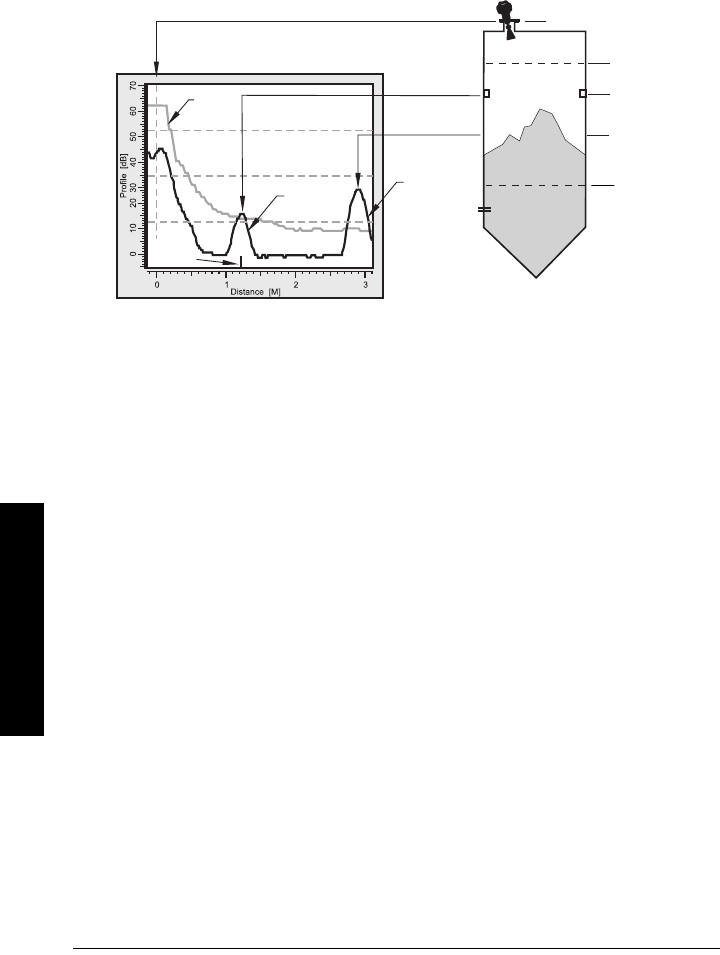
Page 104 SITRANS LR260 (PROFIBUS PA)– OPERATING INSTRUCTIONS A5E32337685
mmmmm
D: Technical Reference
Higher order mathematical techniques and algorithms are used to provide intelligent
processing of microwave reflection profiles. This “knowledge based” technique
produces superior performance and reliability.
Time Varying Threshold (TVT) Curves
A Time Varying Threshold (TVT) curve hovers above the echo profile to screen out
unwanted reflections (false echoes).
In most cases the material echo is the only one which rises above the default TVT curve.
In a vessel with obstructions a large false echo may rise above the default TVT. The Auto
False Echo Suppression feature (see below) can be used to screen it out.
The device characterizes all echoes that rise above the TVT as potential good echoes.
Each peak is assigned a rating based on its strength, area, height above the TVT, amongst
other characteristics.
The true echo is selected based on the setting for the Echo selection algorithm [Algorithm
(2.2.3.1.1.)].
Echo Lock
If the echo selected by Algorithm is within the Echo Lock window, the window is centered
about the echo, which is used to derive the measurement.
•Echo Lock Off:
SITRANS LR260 responds immediately to a new selected echo (within the
restrictions set by the Maximum Fill / Empty Rate), but measurement reliability is
affected.
Echo Position Detection
The echo position algorithm (
2.2.3.1.3. Position
) determines which point on the echo will
be used to calculate the precise time of flight, and calculates the range using the
calibrated propagation velocity (adjusted by a propagation factor, if necessary).
The options are Center or CLEF (Constrained Leading Edge Fit), Hybrid, or Rising Edge.
CLEF uses the leading edge of the echo. It can be used to compensate for materials with
High Cal. Pt.
= 0
obstruction
at 1.2 m
material level
at 2.9 m
echo
marker
false
echo
true
echo
TVT
curve
sensor reference point
Low Cal. Pt.
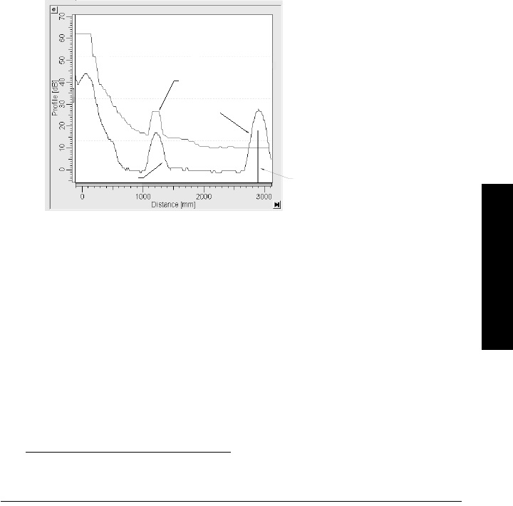
A5E32337685 SITRANS LR260 (PROFIBUS PA) – OPERATING INSTRUCTIONS Page 105
mmmmm
D: Technical Reference
a low dK value, which may cause the vessel bottom to be reported as the level instead of
the actual material level, in low level conditions. CLEF range is the level below which the
CLEF algorithm will be used: above this level the Center algorithm is used.
Center of Mass selects the center of the echo for evaluation. Rising Edge selects the
rising edge of the echo. Hybrid uses a combination of Center and CLEF, depending on the
setting for CLEF range.
Auto False Echo Suppression
If an obstruction is causing a large echo before the material level echo, that echo will rise
above the default TVT curve and may be selected as the true echo. Auto False-Echo
Suppression modifies the TVT curve so that the false echo will not rise above the TVT
curve.
When you use Auto False Echo Suppression, the device first learns the echo profile at
that moment1). A learned TVT curve follows the echo profile and rises above the false
echo. You set Auto Suppression Range so that the learned profile replaces the default
TVT curve up to a point past the obstruction. From that point on, the default TVT curve is
used. The material level echo rises above this, and is selected as the true echo.
Measurement Range
Near Range
2.2.3.5.1. Near Range
programs SITRANS LR260 to ignore the zone in front of the antenna.
The default blanking distance is 50 mm (1.97") from end of horn antenna.
Near Range allows you to increase the blanking value from its factory default. But
2.2.4.3.
Auto False Echo Suppression (AUTO ECHO SUPP)
is generally recommended in
preference to extending the blanking distance from factory values.
1) Use Auto False Echo Suppression when the material level is substantially lower than pro-
cess full level (ideally when the tank is empty or almost empty).
Example after Auto
False Echo Suppression
learned
TVT curve
level
Level (db)
false echo echo marker
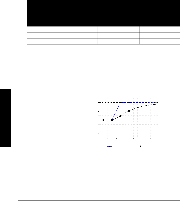
Page 106 SITRANS LR260 (PROFIBUS PA)– OPERATING INSTRUCTIONS A5E32337685
mmmmm
D: Technical Reference
Far Range
In applications where the base of the vessel is conical or parabolic, a reliable echo may
be available below the vessel empty distance, due to an indirect reflection path.
Increasing the range extension to 30% or 40% can provide stable empty vessel readings.
Measurement Response
The measurement response (Response Rate (1.2.)) limits the maximum rate at which the
display and output respond to changes in the measurement. Once the real process fill/
empty rate (m/s) is established, a response rate can be selected that is slightly higher
than the application rate. The response rate automatically adjusts the filters that affect
the output response rate.
There are three preset options: slow, medium, and fast.
Damping
A damping filter smooths out the response to a sudden change in level. This is an
exponential filter and the engineering unit is always in seconds. The setting can be
modified in Filter Time Constant (FILTER TIME CONST) (2.3.1.4.).
Loss of Echo (LOE)
A loss of echo (LOE) occurs when the calculated measurement is judged to be unreliable
because the echo confidence value has dropped below the echo confidence threshold.
Response
Rate (1.2.)
Fill Rate (FILL RATE/
MIN) (2.2.6.2.)/
Empty rate (EMPTY
RATE/MIN) (2.2.6.3.)
Filter Time
Constant (FILTER
TIME CONST)
(2.3.1.4.)a)
a) Numbering depends on AIFB selected.
Shots (2.2.3.3.1.)
Slow 0.1 m/min 60 s 25
Medium 1 m/min 10 s 10
Fast * 10 m/min 0 s 10
0
0.5
1
1.5
2
2.5
3
3.5
4
4.5
1234567
Series1 Series2
Level (m)
Time (s)
smoothed output
input (level)
Damping example
time constant = 2 seconds
input (level) change = 2 m
In 5 time constants the output rises
exponentially:
from 63.2% of the change in the
first time constant, to almost 100%
of the change by the end of the 5th
time constant.

A5E32337685 SITRANS LR260 (PROFIBUS PA) – OPERATING INSTRUCTIONS Page 107
mmmmm
D: Technical Reference
If the LOE condition persists beyond the time limit set in
2.4.1. LOE Timer
the LCD displays
the Maintenance Alarm icon, and the text region displays the fault code S: 0 and the text
LOE.
If two faults are present at the same time, the fault code, error text, and error icon for
each fault are displayed alternately. For example, Loss of Echo and Temperature Sensor
Failure.
S: 0 LOE S: 11 Temp. Sensor Failure
LOE (Loss of Echo) Timer
LOE Timer determines the time to elapse after the last valid reading before a Fail-safe
state is activated. Fail-safe Material Level determines the level to be reported when the
Fail-safe timer expires. Upon receiving a reliable echo, the loss of echo condition is
aborted, the Service Required icon and error message are cleared, and the reading
return to the current level.
Fail-safe Mode
The purpose of the Fail-safe setting is to put the process into a safe mode of operation in
the event of a fault or failure. The value to be reported in the event of a fault is selected so
that a loss of power or loss of signal triggers the same response as an unsafe level.
Fail-safe mode may be triggered by a loss of echo, a bad configuration, or certain device
faults. You can select on of three possible values to be reported when a Fail-safe mode is
activated.
Fail-safe value
When the LOE Timer (2.4.1.) expires, the material level to be reported is determined by
Fail-safe Mode. If the option Use substitute value is selected, a user-defined value can be
reported.
The two Analog Input Function blocks are set separately. For example, to set a user-
defined value for AIFB1:
•Set Fail-safe Mode FB1 (FS MODE FB1) (2.4.2.) to Use substitute value.
•Go to Fail-safe Value FB1 (FS VALUE FB1) (2.4.3.) and enter the desired value.
Material level to be reported
Options
Substitute value (Default value used as output value).
* Last value (Store last valid output value).
Use bad value (Calculated output value is incorrect).

Page 108 SITRANS LR260 (PROFIBUS PA)– OPERATING INSTRUCTIONS A5E32337685
mmmmm
D: Technical Reference
Process Pressure/Temperature derating curves1)
Notes:
• The Process Device Tag shall remain with the process pressure boundary
assembly1. In the event the instrument package is replaced, the Process Device Tag
shall be transferred to the replacement unit.
• SITRANS LR260 units are hydrostatically tested, meeting or exceeding the
requirements of the ASME Boiler and Pressure Vessel Code and the European
Pressure Equipment Directive.
• The serial numbers stamped in each process connection body, (flange, threaded, or
sanitary), provide a unique identification number indicating date of manufacture.
Example: MMDDYY – XXX (where MM = month, DD = day, YY = year, and
XXX= sequential unit produced)
Further markings (space permitting) indicate flange configuration, size, equivalent
pressure class, material, and material heat code.
WARNINGS:
• Never attempt to loosen, remove or disassemble process connection or
instrument housing while vessel contents are under pressure.
• This product is designated as a Pressure Accessory per Directive 97/ 23 / EC
and is not intended for use as a safety device.
• Materials of construction are chosen based on their chemical
compatibility (or inertness) for general purposes. For exposure to
specific environments, check with chemical compatibility charts
before installing.
• The user is responsible for the selection of bolting and gasket materials
which will fall within the limits of the flange and its intended use and
which are suitable for the service conditions.
• Improper installation may result in loss of process pressure and/or
release of process fluids and/or gases.
1) The process pressure boundary assembly comprises the components that act as a barrier
against pressure loss from the process vessel: that is, the combination of process connec-
tion body and emitter, but normally excluding the electrical enclosure.
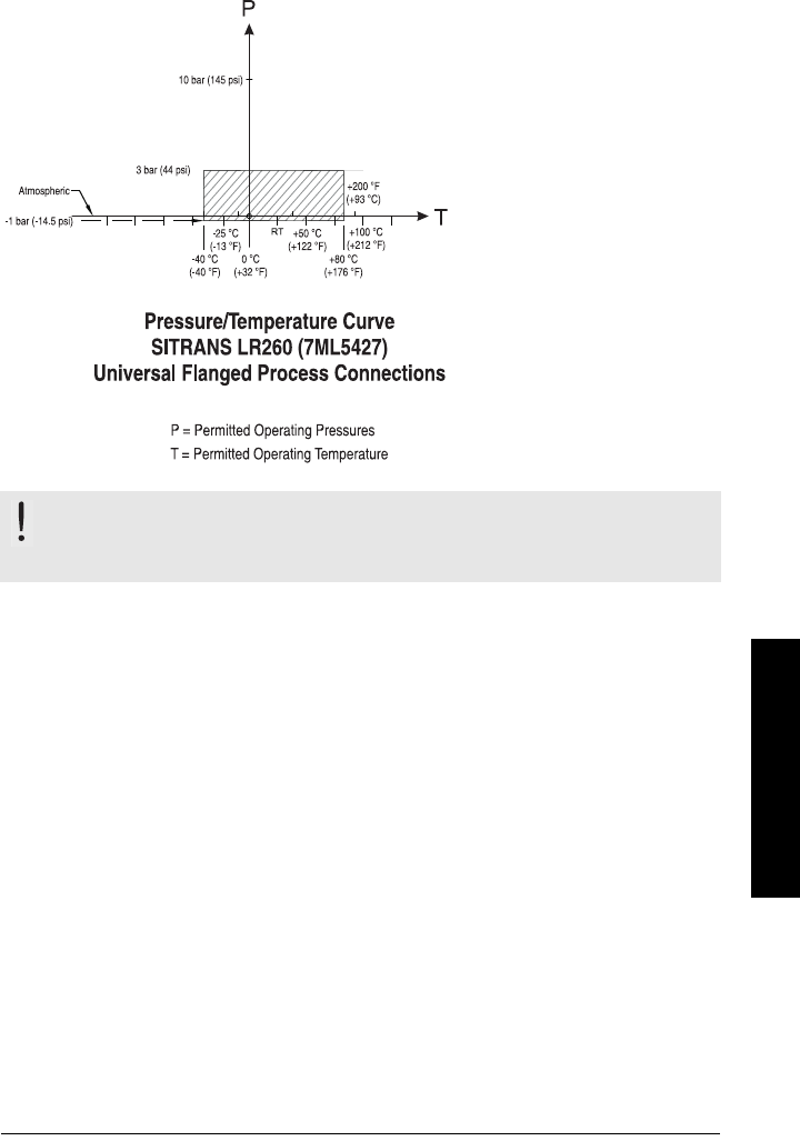
A5E32337685 SITRANS LR260 (PROFIBUS PA) – OPERATING INSTRUCTIONS Page 109
mmmmm
D: Technical Reference
Horn Antenna
2" (50 mm), 3" (80 mm), 4" (100 mm), and 6" (150 mm)
Flanged Versions
WARNING: Never attempt to loosen, remove or disassemble process
connection or instrument housing while vessel contents are under
pressure.
Process Connection Series:
• 51262 or 51263 series
flange.
• Ensure your instrument
has the process
identification Tag showing
one of this series, and
25589 stamped on flange.

Page 110 SITRANS LR260 (PROFIBUS PA)– OPERATING INSTRUCTIONS A5E32337685
mmmmm
D: Technical Reference
Notes
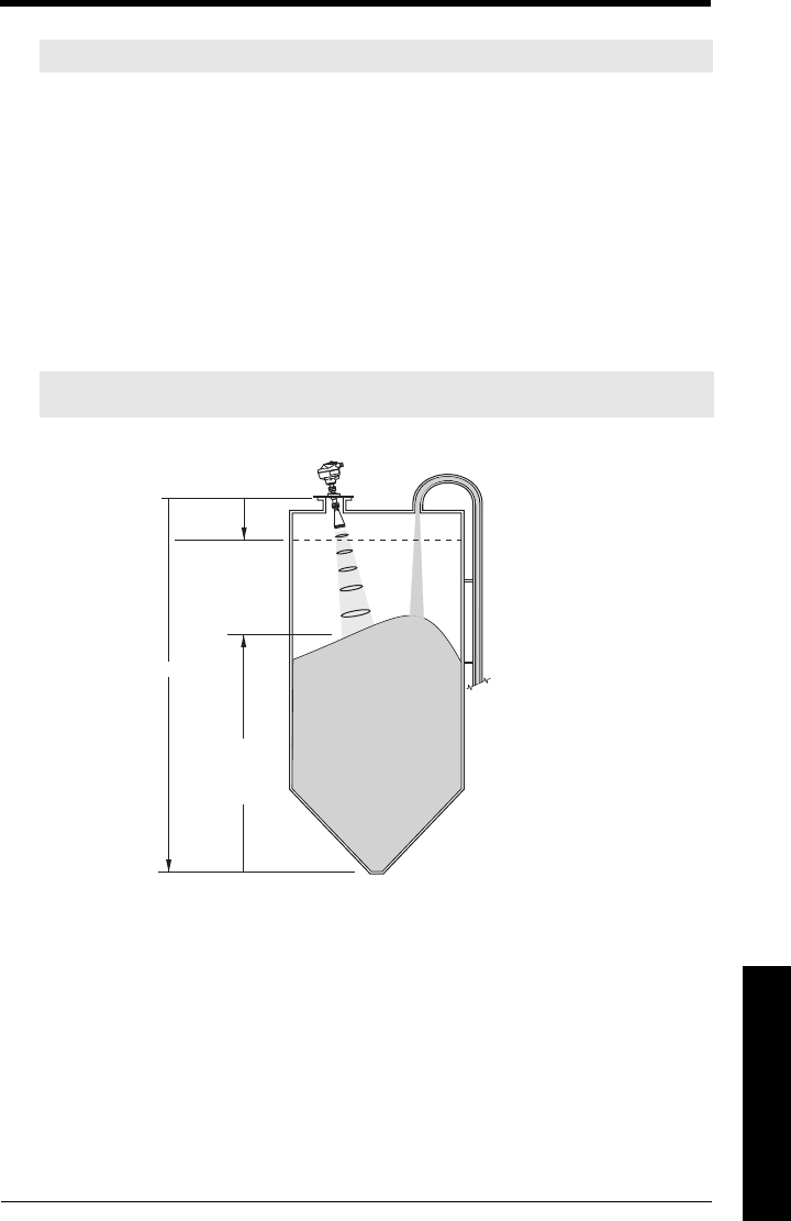
A5E32337685 SITRANS LR260 (PROFIBUS PA) – OPERATING INSTRUCTIONS Page 111
mmmmm
E: Special Applications
Appendix E: Application Example
You can use this examples as setup references. Enter the values in the parameter tables
to select the corresponding functions.
Configure the basic settings using the Quick Start wizard parameters. (These parameters
are inter-related, and changes take effect only after you select YES in step 7 (or Finish
and Transfer in PDM) to apply changes.)
In each example, after performing a Quick Start, navigate to the other required
parameters (either via the handheld programmer, or via SIMATIC PDM) and enter the
appropriate values.
Flour in steel storage vessel, level measurement
Note: In the applications illustrated below, values are for example purposes only.
Note: Minimum distance from flange face to target is limited by
Near Range 2.2.3.5.1.
on page 60
.
To obtain level measurement
proportional to flour levels:
Low Calibration Pt. = vessel
bottom
High Calibration Pt.= 0.5 m
from sensor reference point.
Max.fill/empty rate = 0.1 m/
min.
In the event of a loss of echo,
SITRANS LR260 is to go into
Fail-safe High after 2 minutes.
Sensor
Reference Point
level
Low
Calibration
Point
High
Calibration
Point
16 m
0.5 m
SITRANS LR260

Page 112 SITRANS LR260 (PROFIBUS PA) – OPERATING INSTRUCTIONS A5E32337685
mmmmm
E: Special Applications
Press Mode to return to Measurement mode.
Parameter
type Parameter Name/No. Options/
Values Function
Quick Start
Wizard
parameters
Application Type (1.1.) STEEL
Response Rate (1.2.) MED Medium =1 m/minute
Units (1.3.) Mmeters
Operation (1.4.) LEVEL Level
Low Calibration Point (LOW
CALIB. PT.) (1.5.) 16 16 m
High Calibration Point (HIGH
CALIB. PT.) (1.6.) 0.5 0.5 m
Apply? (Apply changes) (1.7.) YES Transfers Quick Start settings to
device.
Independent
parameters
LOE Timer (2.4.1.) 22 minutes
Fail-safe Mode FB1 (FS MODE
FB1) (2.4.2.)
Substitute
value User-defined value to be used.
Fail-safe Value FB1 (FS VALUE
FB1) (2.4.3.) 4.5 4.5 m
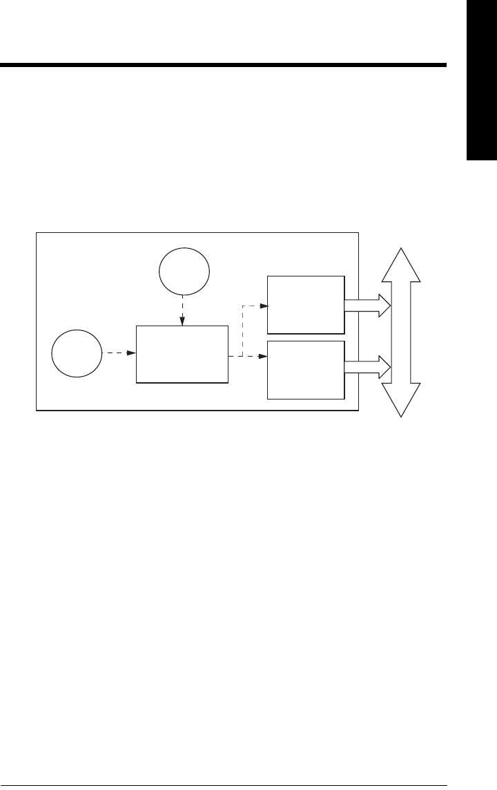
A5E32337685 SITRANS LR260 (PROFIBUS PA) – OPERATING INSTRUCTIONS Page 113
mmmmm
F: Profile structure
Appendix F: PROFIBUS PA Profile
Structure
PROFIBUS Level Device Design
The device follows the profile block model and is implemented as a Profile 3.01, Class B,
PA device. Standard profile parameters are used to program the level transducer block.
Block Model for recording and processing measured values
The functions of the device are divided into blocks for different areas of responsibility.
They can be parameterized by acyclic data transfer via PDM.
The device is implemented with one Physical Block (PB1), one Level Transducer Block
(LTB1), and two Analog Input Function Blocks (AIFB1 and AIFB2).
All data is viewed from the perspective of the DCS or PLC, so information from the sensor
is an input.
Transducer Block (TB)
The Level Transducer Block (LTB) carries out adjustments to the sensor, such as level
calibration. It supplies the outputs utilized by either or both of the AIFBs.
Analog Input Function Blocks AIFB1 and AIFB2
The two AIFBs are completely independent of each other. They utilize the output from the
Level TB, and apply any required quality checks, scaling, and Fail-safe operation
selections.
The output of an Analog Input Function Block supplies the measured value and
associated status information to PROFIBUS PA, via cyclic data transfer.
sensor
sensor
Transducer Block
electronics
temperature
Analog Input
Function Block2
Analog Input
Function Block1
PROFIBUS PA
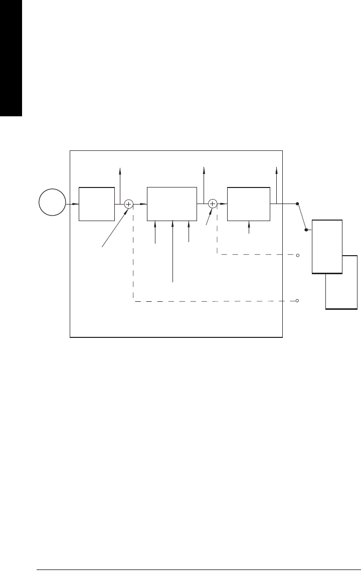
Page 114 SITRANS LR260 (PROFIBUS PA) – OPERATING INSTRUCTIONS A5E32337685
mmmmm
F: Profile structure
Description of the blocks
Transducer block function groups
The figure below shows the signal flow of measured values from the sensor through the
Transducer block into the output value:
• Primary Value (PV): Level
• Secondary Value 1 (SV1): Level/Volume
• Secondary Value 2 (SV2): Distance
The Level TB implements all of the basic parameters.
How the LTB works
1. The sensor technology block selects the proper echo. For an explanation of sensor
technology, see
Appendix D: Technical Reference
, page 103 onwards.
The sensor value (in sensor units) is checked to see if it is within its measuring limits.
If the limit is exceeded, this results in a Bad status and the error message Failure in
measurement. The sensor value is stored in Sensor Value.
The analog signal from the sensor is transformed into a digital signal.
A Sensor Offset (default 0) provides compensation if necessary for changes in the
sensor.
Level Transducer Block
Sensor Value
Sensor Sensor
technology
Level
calibration Linearization
Level Primary Value
Level
(level units)
(Analog
Input)
AIFB1
Secondary Value 1
[Level]
(Level Units)
Secondary Value 2
[Distance]
(Sensor Units)
Sensor
Offset
Level
Offset
High
Calibration
Point
High Level
Point
Low
Calibration
Point
Low Level
Point
Calibration
Type
Linearization
Type
PV
SV1
SV2
AIFB2
(Analog
Input)
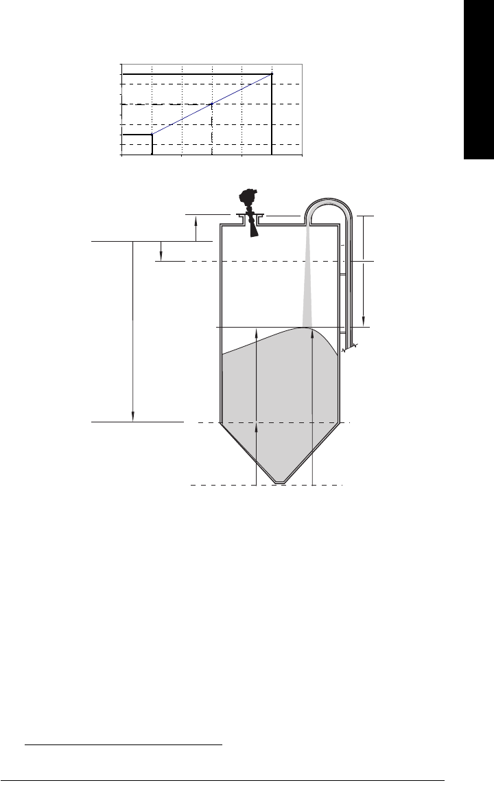
A5E32337685 SITRANS LR260 (PROFIBUS PA) – OPERATING INSTRUCTIONS Page 115
mmmmm
F: Profile structure
2. Level Calibration is a linear transfer function that converts a sensor value to a level
value.1)
3. The LTB provides four possible outputs
• Primary Value (PV) / Level/Volume
• Secondary Value 1 (SV1) / Level
• Secondary Value 2 (SV2) / Distance (sensor units)
Electronics temperature
The transducer block also monitors the internal temperature of the device electronics. If
the temperature exceeds permitted limits, it does not change the sensor value, but it does
change the status.The permitted limits correspond to those of the permitted ambient
temperature.
1) Level Offset (default O) can compensate for specific vessel configurations.
0
0.5
1
1.5
2
2.5
3
3.5
4
4.5
Low Calibration Point Sensor Value High Calibration Point
Level
High Level Point
Low Level Point
Calibration
Level Value
High Level Point
(default: 100%)
Sensor Reference Point (flange face)
Sensor Value
Low Level Point
(default: 0%)
Level
Level Offset1Secondary
Value 1
Low
Calibration
Point
Sensor Offset
High Calibration
Point
distance/SV2
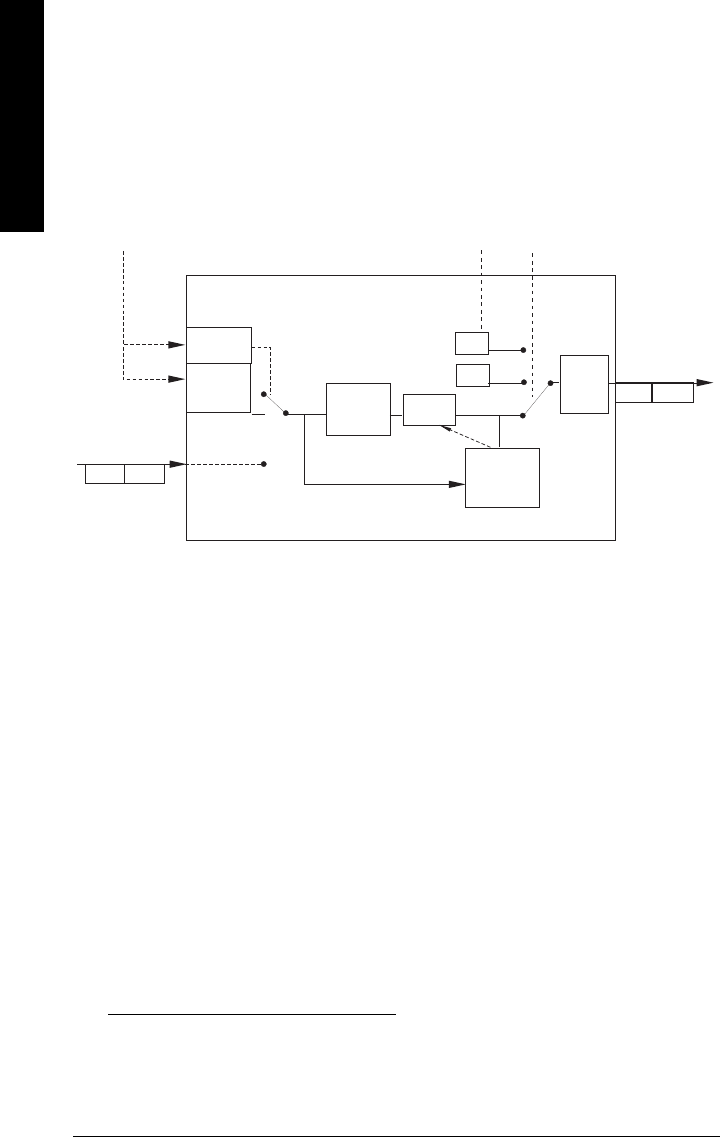
Page 116 SITRANS LR260 (PROFIBUS PA) – OPERATING INSTRUCTIONS A5E32337685
mmmmm
F: Profile structure
If a temperature limit is exceeded, the status changes. Peak indicators1) allow you to
check the maximum and minimum temperatures that have occurred.
Analog Input Function Blocks 1 and 2
The figure below shows how measured values are processed within the two Analog
Input Function Blocks (AIFB1 and AIFB2) to produce the device outputs, which are
communicated via cyclic transfer to PROFIBUS PA, and displayed on the LCD.
Analog Input Function Block function groups (simulation, mode and status)2)
How the AIFBs work
The Analog Input Function Blocks allow you to control modifications to the output value
(PROFIBUS cyclic data).
Output Conversion
Values transmitted by the Level TB have a status attached. The decision on what to do
with each value is made by the Analog Input Function Block.
Device/ Input Simulation
The input can be a simulated value instead of a TB OUT value. This allows the AI block to
be tested independently of the characteristics of the environment.
Fail-safe
If the status of the Primary Value or Simulation Value is bad, the fault logic can output
either the last usable measured value, or a given substitute value.
1) Open the menu View – Peak Values.
2) The output from the Level Transducer Block can be called the Primary Value (or
Secondary Value). When it becomes the input to the AIFB, it is called the Process
Variable.
enable
on
FB
algorithm
Status
OUT
AUTO
MODE and
STATUS
handling
Process Variable2
from LTB
(Function Block
input)
Value Status
Alarm
Limit
Check
Out of
Service
OUT
OUT
MAN
Value
simulate
value and
status
Value Status
Operator Operator
off
Simulate
Parameter
Fail-
safe
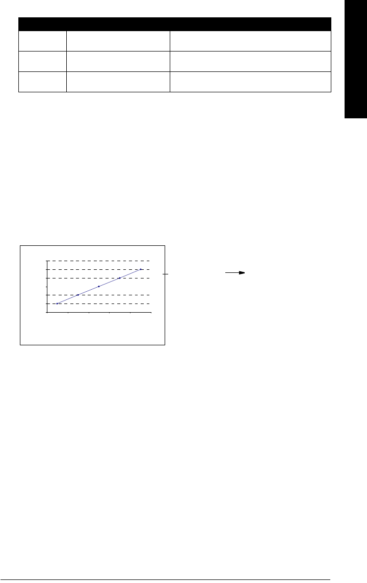
A5E32337685 SITRANS LR260 (PROFIBUS PA) – OPERATING INSTRUCTIONS Page 117
mmmmm
F: Profile structure
Device / Output Simulation
One of three settings can be selected: the result is the output parameter (OUT).
AIFB execution steps:
The AIFBs can provide a linear conversion to any desired units.
1. The input value is normalized (Scaling Input)
Process Variable range applies to any of the four LTB values. (Units of the Process
Variable scale are the same as the units used for the LTB output.) Output units
together with Process Variable range determine how the LTB output is converted to
whatever units the customer wants.
2. The scaling output is applied.
For example:
3. This value is filtered using a first order filter based on a time constant provided by
the user.
4. The status of the Process Variable (input value) is checked. If the status is Bad, a
Fail-safe condition occurs. The output is determined by the Fail-safe Mode of the
block.
5. The target mode parameter allows the entire AI block to be overridden by a Manual
Out value.
6. The value is checked against the user parameterized warning and alarm limits.
(There is an upper and lower warning limit and an upper and lower alarm limit. The
unit of the limits corresponds to the unit of the output range. A hysteresis parameter
prevents toggling in the Status field of the OUT value.)
7. The OUT VALUE parameter is the value for the cyclic data transfer.
Setting description Output value
AUTO automatic the automatically-recorded measured value
MAN manual a manually-set fixed simulation value
O/S function block disabled the preset safety value.
0
1
2
3
4
5
6
12345
AIFB2
Process Variable range
(typical Input (0 to 100%)
Output range:
Out (or AIFB2 Out) straight to LCD
(same values displayed
on LCD as PLC)

Page 118 SITRANS LR260 (PROFIBUS PA) – OPERATING INSTRUCTIONS A5E32337685
mmmmm
F: Profile structure
Notes

A5E32337685 SITRANS LR260 (PROFIBUS PA) – OPERATING INSTRUCTIONS Page 119
mmmmm
G: Communications PA
Appendix G: Communications via
PROFIBUS PA
SITRANS LR260 (PROFIBUS PA) is a Profile Version 3.01, Class B, PA device. It supports
Class 1 Master for cyclic and acyclic data exchange, and Class 2 for acyclic services.
The full range of SITRANS LR260 functions is available only over a PROFIBUS PA
network.
PROFIBUS PA is an open industrial protocol. Full details about PROFIBUS PA can be
obtained from PROFIBUS International at www.profibus.com.
Device Configuration tool
To use PROFIBUS PA, you will need a PC configuration tool: we recommend
SIMATIC PDM. Please consult the operating instructions or online help for details on
using SIMATIC PDM. (You can find more information at www.fielddevices.com: go to
Products and Solutions > Products and Systems > Communications and Software >
Process Device Manager.)
SIMATIC PDM
SIMATIC PDM is a software package used to commission and maintain SITRANS LR260
and other process devices. For more detail see
Functions in SIMATIC PDM
on page 37.
Electronic Device Description
In order to use Process Device Manager (PDM) with PROFIBUS PA, you will need the
Electronic Device Description for SITRANS LR260. For details see
Electronic Device
Description (EDD)
on page 38.
Network Configuration
To configure a PROFIBUS PA Class 1 Master (for example, a PLC), you will need a GSD
file.
The GSD file
The GSD file SIEM8162.gsd is available from the SITRANS LR260 product page on our
web site. Go to www.siemens.com/LR260 and click on Downloads.
Bus Termination
Note: PROFIBUS PA MUST be terminated at both extreme ends of the cable for it to
work properly. Please refer to the PROFIBUS PA User and Installation Guidelines (order
number 2.092), available from www.profibus.com.

Page 120 SITRANS LR260 (PROFIBUS PA) – OPERATING INSTRUCTIONS A5E32337685
mmmmm
G: Communications PA
Power Demands
To determine how many devices can be connected to a bus line, calculate the combined
maximum current consumption of all the connected devices: 15 mA for SITRANS LR260.
Allow a current reserve for safety.
PROFIBUS address
A unique PROFIBUS address identifies each device on the network. To set the PROFIBUS
address see Device Address (5.1.) on page 88.
Resetting the PROFIBUS address to 126:
• Via SIMATIC PDM:
a) Open the menu Device – Device Reset and click on Reset Address to 126.
b) Click on OK: the address will be reset to 126, and if the address lock was on, it
will be disabled.
• Via the handheld programmer:
a) Navigate to Service (4.) > Device Reset (4.1.). (You can enter the numeric value
instead of navigating via the Arrow keys.)
b) Press RIGHT Arrow to open Edit Mode then scroll down to DEV ADDRESS and
press RIGHT Arrow to select it. The address will be reset to 126, and if the
address lock was on, it will be disabled.
c) Press LEFT Arrow to exit.
Operating as a Profile Device
Every manufactured PROFIBUS product has a unique PROFIBUS identification number
which identifies it to the system. PROFIBUS Profile Standard version 3.01 also defines a
Profile Model which can identify a product as a generic profile device on the network.
SITRANS LR260 can be identified in one of three ways:
Notes:
• It is possible to change the device address via a Class 1 master (for example, a PLC)
and lock the device address to prevent further changes.
• If this Address Lock is on, the PA address cannot be changed. This lock can be
disabled only by performing an Address Reset.
Device Identification Profile Model
STD PROFILE Standard Profile (uses generic GSD for 2 AIFB [ident # =
0x9701]
* MANUFACTURER Manufacturer-specific (uses Siemens EDD and GSD file,
which identifies the LR260 [PROFIBUS PA]) [ident # = 0x8162]
STD – AIFB 1 ONLY Standard Profile AIFB 1 only (uses generic GSD for 1 AIFB)
[ident # = 0x9700]

A5E32337685 SITRANS LR260 (PROFIBUS PA) – OPERATING INSTRUCTIONS Page 121
mmmmm
G: Communications PA
Defining the device as Profile-specific as opposed to Manufacturer-specific makes it
possible to exchange the device for any other device of the same profile type without
changing the GSD file.
To set up SITRANS LR260 as a profile device see PROFIBUS Ident Number (PROFIBUS
IDENT) (4.4.) on page 85.
Configuring a device
See
Configuring a new device
on page 38.
Configuring PROFIBUS PA with an S7-300/ 400 PLC
1. If SITRANS LR260 is not listed in the STEP 7 device catalog, you can download the
DeviceInstall file from the Siemens Milltronics Web site and run it from your
computer. Go to https://pia.khe.siemens.com/index.asp?Nr=7427 and click on
Downloads.
2. Add the SITRANS LR260 “rack”: click on and drag the SITRANS LR260 folder from
the hardware catalog.
3. Fill the rack with desired modules, by dragging and dropping them from the
hardware catalog.
4. After configuring PROFIBUS PA in steps 2 and 3, download it to the PLC.
5. Add code to the PLC program to read data consistently using the SFC14.
Cyclic versus Acyclic Data
When you request data from a device via PROFIBUS PA, you have two choices. Cyclic
data is provided at every bus scan: acyclic data is requested and provided as needed.
Input information is always requested at every bus scan and is set up as cyclic data.
Configuration information is only needed periodically and is set up as acyclic data.
Cyclic Data
When you configure SITRANS LR260 on the PROFIBUS PA bus, there are two slots
available for modules.
Slot 0 always transmits AIFB1 information1); slot 1 defaults to Free Place, but can be
changed to AIFB2 information. If you do not wish to have data transmitted, then you must
use a Free Place module in that slot.
Each of the two Analog Input Function Blocks can be set up to return Level, or Distance.
Within the function blocks, the values are scaled according to the user requirements
(please see
Analog Input Function Blocks 1 and 2
on page 116 for details).
Note: Each of the slots has to have a module defined in it.
1) For more information, please see
Analog Input Function Blocks 1 and 2
on
page 116.

Page 122 SITRANS LR260 (PROFIBUS PA) – OPERATING INSTRUCTIONS A5E32337685
mmmmm
G: Communications PA
AIFB1 and AIFB2 return 5 bytes of data each:
The first 4 bytes are the floating point representation (IEEE) of the variable. The variables
are the outputs of the function block. The 5th byte is the status word and the list of
possible values is given in the chart below.
The 5 bytes must be read consistently, in a contiguous chunk: they cannot be read byte by
byte, and cannot suffer an interrupt. If you are using an S7-300 / 400, you will need to use
SFC14 DPRD_DAT: Read Consistent Data of a Standard DP Slave.
Status Byte
In PROFIBUS PA there are two possible types of status byte:
•status byte: originally defined in Profile Standard V3.0
•condensed status: an alternative status byte defined in Profile Standard V3.01
You can choose which type of status byte will be returned, by enabling or disabling
Condensed Status Mode (COND. STAT. MODE) (3.6.1.). The default setting is Condensed
Status enabled:
Condensed Status
These codes are available when Condensed Status is enabled. See Condensed Status
Setup (COND. STAT. SETUP) (3.6.) on page 80 for more details.
Condensed Status
Hex
value Status – GOOD Description
0x80 GOOD – ok No error or special condition is associated with this value.
0x84
...0x87 GOOD – update event Set if the value is good and the block has an active Update
event. (This status remains active for 20 seconds.)
0x89,
0x8A
GOOD – active advi-
sory alarm Set if the value is good and the block has an active Alarm.
0x8D,
0x8E
GOOD – limit check/
update event See
Status Codes for Good Quality
on page 124.
0xA0
...0xA3
GOOD – initiate fail
safe
This fault is not generated by the product, but can be simu-
lated.
0xA4
...0xA7
GOOD – maintenance
required
Value is valid. Maintenance is recommended within a
medium-term period.
0xA8
...0xAB
GOOD – maintenance
demanded
Value is valid. Maintenance is demanded within a short-
term period.
0xBC
...0xBF
GOOD – function
check
Device performs internal function check without influenc-
ing the process. Value is valid.
Floating Point Status
AIFB2
AIFB1 byte 1 byte 2 byte 3 byte 4 byte 5
byte 6 byte 7 byte 8 byte 9 byte10byte10

A5E32337685 SITRANS LR260 (PROFIBUS PA) – OPERATING INSTRUCTIONS Page 123
mmmmm
G: Communications PA
Condensed Status
Hex
value
Status –
UNCERTAIN Description
0x4B UNCERTAIN – substi-
tute set
Output of Failsafe logic only.
0x4F UNCERTAIN – initial
value
Default value as long as no measured value is available
or until a diagnosis is made that affects the value and
the status accorded to it.
0x68
...0x6B
UNCERTAIN – main-
tenance demanded
Usability of the process value depends on the applica-
tion.
Value is potentially invalid. Cause is a weara) detected
in the device. Maintenance is demanded within a
short-term period.
a) See
Wear
on page 49 for more detail.
0x73 UNCERTAIN – simu-
lated value, start
Indicates the start of a simulation.
Simulation of a measured value or Input FB mode
changes from AUTO to MAN.
• This status remains active for at least 10 seconds:
– after enabling simulation
– after setting the FB to MAN mode
– after a restart (e.g. power down cycle) if the simu-
lation is enabled or the FB is in MAN mode
– after passivation is cleared if simulation is
enabled or the FB is in MAN mode
• In MAN mode the status remains until a subsequent
write command overwrites the OUT value after the
10 seconds have expired.
• In simulation mode the written status is buffered and
appears in the value flow after 10 seconds. However
the new written SIMULATE parameter with its status
can be read before the 10 seconds have expired.
0x74
...0x77
UNCERTAIN – simu-
lated value, end
Indicates the end of a simulation.
Simulation of a measured value is disabled or Input FB
mode changes from MAN to AUTO.
This Status remains active for 10 seconds after simula-
tion ends.
While this status is active there is no reliable process
value. Measured values and their status are updated
afterwards.

Page 124 SITRANS LR260 (PROFIBUS PA) – OPERATING INSTRUCTIONS A5E32337685
mmmmm
G: Communications PA
Status Byte
When Condensed Status is disabled, Status Byte will be returned, and the following
codes will be used.
Condensed Status
Hex
value Status BAD Description
0x00 BAD – non specific Proxy determines that a device does not
communicate.
0x23 BAD – passivated (diagnostics
alerts disabled)
Configured failsafe value is used,
accompanied by this status.
0x24
...0x27
BAD – maintenance alarm, more
diagnosis available
No measurement available because of a
failure.
0x2B BAD – process related, no mainte-
nance
No measurement available because of
invalid process conditions.
0x3C
...0x3F
BAD – function check / local over-
ride, value not usable
Occurs during cleaning or calibration
process.
Status Codes for Good Quality
Values in hex notation Description
0x80 Data is GOOD.
0x84...0x87 A parameter in the function block has been changed: status active
for 20 s
0x89 Active low warning.
0x8A Active high warning.
0x8D Active low alarm.
0x8E Active high alarm.
Status Codes for Uncertain Quality
Values in hex notation Description
0x4B Value is a substituted value (normally used in Failsafe).
0x4C...0x4F Initial value.
0x44...0x47 Last usable value.

A5E32337685 SITRANS LR260 (PROFIBUS PA) – OPERATING INSTRUCTIONS Page 125
mmmmm
G: Communications PA
Diagnostics
All diagnostic information shown below is viewable via PDM.
Diagnosis reply (available cyclically)
During DPV0 data exchange, the PROFIBUS PA slave will notify the Master when a
serious error occurs. The Master will then send a Diagnosis request. The reply to this
request is normally logged in the PLC and is referred to as the "Hex values."
The reply may contain two parts. The first part is 6 bytes long and is defined by the
PROFIBUS standard. If there is a second part, it is called the ’extended cyclic diagnosis’
and it is 8 bytes long. The last 4 bytes of the extended diagnostic message give the error
code shown. (See
Extended Mode Diagnosis
on page 126 and
Condensed Mode
Diagnosis
on page 126.)
The same infomration is also available acyclically via the Diagnosis Object.
Diagnosis Object (available cyclically or acyclically)
This consists of four bytes.
In PROFIBUS PA there are two possible types of Acyclic Diagnostics:
•Extended Mode Diagnosis
•Condensed Mode Diagnosis
You can choose which of these will be returned, by enabling or disabling Condensed
Status Mode (COND. STAT. MODE) (3.6.1.) on page 80. The default setting is Condensed
Status enabled: Extended Mode Diagnosis will be returned, and the following codes will
be used.
Status Codes for Bad Quality
Values in hex notation Description
0x10...0x1C The LOE timer has expired: this could be caused by LOE or by
a sensor malfunction: value is BAD.
0x04...0x07 There is an error in the configuration of the function blocks in
PROFIBUS PAa).
0x1C...0x1F The function block, or the transducer block, has been placed
out of service.
a) This could happen when a firmware download has been done, but a system reset has not
been done. This could also happen if the function blocks are not configured properly
using the handheld programmer, PDM or acyclic services.
Cyclic Diagnosis (6 bytes) Extended Cyclic Diagnosis (8 bytes)
Diagnosis Object
(last 4 bytes)
Condensed
Mode Diagnosis
Extended Mode
Diagnosis

Page 126 SITRANS LR260 (PROFIBUS PA) – OPERATING INSTRUCTIONS A5E32337685
mmmmm
G: Communications PA
Extended Mode Diagnosis
Values of the DIAGNOSIS bit: 0 = not set; 1 = set
Condensed Mode Diagnosis
Extended Mode Diagnosis
Hex values Byte Bit Description Indication
classa)
a) R indicates the message remains active as long as the reason for the message
exists.
A indicates the message will automatically reset after 10 seconds
0x01000000
0
0 Electronics failure R
0x02000000 1 Mechanical failure R
0x04000000 2 Motor Temperature too high R
0x08000000 3 Electronics temperature too high R
0x10000000 4 Memory error R
0X20000000 5 Measurement failure R
0X40000000 6 Device not initialized (no calibration) R
0x80000000 7 Self calibration failed R
0x00010000 0Zero point error (limit position) R
0x00020000 1Power supply failure (electrical, pneumatic) R
0x00040000 2Configuration invalid R
0x00080000 3New startup carried out (Warm Start) A
0x00100000 4Restart carried out (Cold Start) A
0X00200000 1 5 Maintenance required R
0X00400000 6Characterization invalid R
0X00800000 7
Set to 1 (one), if the Ident_Number of the
running cyclic data transfer and the value of
Physical Block IDENT__NUMBER_SELECTOR
parameter are different.
R
2 0 to 7 Reserved for use within the PNO
30 to 6 Reserved for use within the PNO
0X00000080 7More diagnosis information is available
Condensed Mode Diagnosis
Hex values Byte Bit Description Indication
classa)
0x01000000
0
0 Reserved for use within the PNO
0x02000000 1 Reserved for use within the PNO
0x04000000 2 Reserved for use within the PNO
0x08000000 3 Reserved for use within the PNO
0x10000000 4 Reserved for use within the PNO

A5E32337685 SITRANS LR260 (PROFIBUS PA) – OPERATING INSTRUCTIONS Page 127
mmmmm
G: Communications PA
Acyclic Extended Diagnostics (General Fault Codes)
In addition to the extended diagnostics available by cyclic data exchange (shown above),
further extended diagnostics are available via acyclic communications. This consists of
six bytes. See
Acyclic Data
on page 130 for information on the location of the Extended
Diagnostics
0x20000000
0 (cont’d)
5 Reserved for use within the PNO
0x40000000 6 Reserved for use within the PNO
0x80000000 7 Reserved for use within the PNO
0x00080000
2
3New startup carried out (Warm Start) A
0x00100000 4Restart carried out (Cold Start) A
0x00200000 5Maintenance required R
0x00400000 6Reserved for use within the PNO
0x00800000 7
Set to 1 (one), if the Ident_Number of the
running cyclic data transfer and the value of
Physical Block IDENT__NUMBER_SELECTOR
parameter are different.
R
0x00010000
3
0 Failure of the device or armature R
0x00020000 1 Maintenance demanded R
0x00040000 2 Device is in function check mode, or simulation,
or under local control e.g. maintenance R
0x00080000 3
The process conditions do not allow the return
of valid values. (Set if a value has the quality
Uncertain - Process related, no maintenance or
Bad - Process related, no maintenance.)
R
4 to 7 Reserved for use within the PNO
4
0 to 6 Reserved for use within the PNO
0x80000000 7
0: There is no more information available
1: More diagnosis information is available in
DIAGNOSIS_EXTENSION
a) R indicates the message remains active as long as the reason for the message exists.
A indicates the message will automatically reset after 10 seconds
Note: Certain fault codes (identified by an asterisk [*] in the table below) will persist
until a manual reset has been performed (see Fault Reset (3.1.) on page 72).
Condensed Mode Diagnosis (cont’d)
Hex values Byte Bit Description (cont’d) Indication
classa) (cont’d)

Page 128 SITRANS LR260 (PROFIBUS PA) – OPERATING INSTRUCTIONS A5E32337685
mmmmm
G: Communications PA
Acyclic Extended Diagnostics /General Fault Codes
LCD
display Meaning Corrective Action Byte Bit
S:0
The device was unable to get a
measurement within the LOE
Fail-safe Timer period. Possible
causes: faulty installation,
material buildup, foaming/other
adverse process conditions,
invalid calibration range.
Ensure installation details are
correct. Ensure no material
buildup. Clean if necessary.
Adjust process conditions to
minimize foam or other adverse
conditions. Correct range
calibration. If fault persists,
contact your local Siemens
representative.
0
0
S:2
Unable to collect profile
because of a low power
condition that is outside of the
operating range of the device.
Repair required. Contact your
local Siemens representative. 2
S:3
Device is nearing its lifetime
limit according to the value set
in Maintenance Required Limit.
Replacement is recommended.
3
S:4
Device is nearing its lifetime
limit according to the value set
in Maintenance Demanded
Limit.
Replacement is recommended.
4
S:6
Sensor is nearing its lifetime
limit according to the value set
in Maintenance Required Limit.
Replacement is recommended.
6
S:7
Sensor is nearing its lifetime
limit according to the value set
in Maintenance Demanded
Limit.
Replacement is recommended.
7
S:8
Service interval as defined in
Maintenance Required Limit
has expired.
Perform service.
1
0
S:9
Service interval as defined in
Maintenance Demanded Limit
has expired.
Perform service.
1
S:10
Input parameters High
Calibration Point and Low
Calibration Point are the same.
Check calibration settings of
device. Ensure settings for High
Calibration Point and Low
Calibration Point are different.
2

A5E32337685 SITRANS LR260 (PROFIBUS PA) – OPERATING INSTRUCTIONS Page 129
mmmmm
G: Communications PA
S:11 Internal temperature sensor
failure. Return the device to the factory.
1
(cont’d)
3
S:12 *
Internal temperature of device
has exceeded specifications: it
is operating outside its
temperature range.
Lower the ambient temperature
enough to cool the device.
Fault code will persist until a
manual reset is performed using
PDM or the LCD interface.
4
S:14
Upper and lower input values
(Process Value Scale) for AIFB1
are the same.
Check configuration for AIFB1.
Ensure that Upper Value and
Lower Value (Process Value
Scale) are not the same.
6
S:15
Upper and lower input values
(Process Value Scale) for AIFB2
are the same.
Check configuration for AIFB2.
Ensure that Upper Value and
Lower Value (Process Value
Scale) are not the same.
7
S: 17
Calibration interval as defined
in Maintenance Required Limit
has expired.
Perform calibration.
2
1
S: 18
Calibration interval as defined
in Maintenance Demanded
Limit has expired.
Perform calibration. 2
S: 25 Internal device error
Reset power. If error persists,
contact your local Siemens
representative.
3
1
S:28 Internal device failure caused
by a RAM memory error.
Repair required: contact your
local Siemens representative. 4
S:29 EEPROM damaged. Repair required: contact your
local Siemens representative. 5
S:31 Flash error. Repair required: contact your
local Siemens representative. 7
Acyclic Extended Diagnostics /General Fault Codes (cont’d)
LCD
display Meaning (cont’d) Corrective Action Byte
(cont’d) Bit

Page 130 SITRANS LR260 (PROFIBUS PA) – OPERATING INSTRUCTIONS A5E32337685
mmmmm
G: Communications PA
Acyclic Data
SITRANS LR260 supports up to four simultaneous connections by a Class 2 Master
(C2 connection). It supports one connection by a Class 1 Master (C1 connection).
In order for a Class 1 Master to read parameters from an instrument, it needs to know the
slot and absolute index of the parameter.
The parameters are all listed in SIMATIC PDM under Help. If you do not have SIMATIC
PDM you can download the EDD and reference the HTML help file directly.
(continued on next page)
S: 32
The IDENT number used in
communications, and number
selected by the Ident Number
Selector do not correspond.
Ensure value of the Ident
number selector is correct for
the network configuration. If it is
correct, the device needs to be
re-parameterized by the PLC.
4
0
S:33
Factory calibration for the
internal temperature sensor
has been lost.
Repair required: contact your
local Siemens representative. 1
S:34 Factory calibration for the
device has been lost.
Repair required: contact your
local Siemens representative. 2
S:35 Factory calibration for the
device has been lost.
Repair required: contact your
local Siemens representative. 3
S:36 Unable to start microwave
module.
Cycle power. If error persists,
contact your local Siemens
representative.
4
S:37 Measurement hardware
problem.
Cycle power. If error persists,
contact your local Siemens
representative.
5
S:38
Microwave module hardware
failure: unable to calculate
distance measurement.
Cycle power. If fault persists,
contact your local Siemens
representative: repair required.
6
S:43 Factory calibration for the radar
receiver has been lost.
Repair required: contact your
local Siemens representative. 53
Acyclic Extended Diagnostics /General Fault Codes (cont’d)
LCD
display Meaning (cont’d) Corrective Action Byte
(cont’d) Bit

A5E32337685 SITRANS LR260 (PROFIBUS PA) – OPERATING INSTRUCTIONS Page 131
mmmmm
G: Communications PA
To find the slot and index numbers via SIMATIC PDM, go to Help > Help on Device
Parameters > Communications, and select the appropriate block from the list. For each
parameter, the slot and the relative index is listed. For example.
Each block has a slot number and an Index Offset value.
To get the absolute index for any parameter, add the Index Offset for the appropriate
block to the relative index for that parameter. The parameter takes the slot number of the
block in which it is located.
For example:
• Parameter Static Revision Number has relative index = 1 and is located on AIFB1.
• It has Absolute Index = 17 (relative index 1 + index offset 16).
• It is located at Slot 1 (the slot number for AIFB 1).
AIFB 1
Index Parameter Datatype
1 Static Revision No. UNSIGNED_INTEGER (2)
Block Name Slot Index Offset
Physical block 0 16
Transducer block 0 77
AIFB 1 1 16
AIFB 2 2 16

Page 132 SITRANS LR260 (PROFIBUS PA) – OPERATING INSTRUCTIONS A5E32337685
mmmmm
G: Communications PA
Notes

A5E32337685 SITRANS LR260 (PROFIBUS PA) – OPERATING INSTRUCTIONS Page 133
mmmmm
Appendix H: Firmware rev.
Appendix H: Firmware Revision History
Firm-
ware
Rev.
EDD Rev. Date Changes
1.00.01 1.00.04 Dec. 5, 2007 • Initial release

Page 134 SITRANS LR260 (PROFIBUS PA) – OPERATING INSTRUCTIONS A5E32337685
mmmmm
Appendix H: Firmware rev.
Notes

A5E32337685 SITRANS LR260 (PROFIBUS PA) – OPERATING INSTRUCTIONS Page 135
mmmmm
Glossary
Glossary
accuracy: degree of conformity of a measure to a standard or a true value.
agitator: mechanical apparatus for mixing or aerating. A device for creating turbulence.
algorithm: a prescribed set of well-defined rules or processes for the solution of a problem in a
finite number of steps.
ambient temperature: the temperature of the surrounding air that comes in contact with the
enclosure of the device.
antenna: an aerial which sends out and receives a signal in a specific direction. There are four
basic types of antenna in radar level measurement, horn, parabolic, rod, and waveguide.
attenuation: a term used to denote a decrease in signal magnitude in transmission from one
point to another. Attenuation may be expressed as a scalar ratio of the input magnitude to
the output magnitude or in decibels.
Auto False-Echo Suppression: a technique used to adjust the level of a TVT curve to avoid the
reading of false echoes. (See TVT.)
Auto False-Echo Suppression Distance: defines the endpoint of the TVT distance. (See TVT.)
This is used in conjunction with auto false echo suppression.
beam angle: the angle diametrically subtended by the one-half power limits (-3 dB) of the
microwave beam.
beam spreading: the divergence of a beam as it travels through a medium.
blanking: a blind zone extending away from the reference point plus any additional shield
length.The instrument is programmed to ignore this zone.
capacitance: the property of a system of conductors and dielectrics that permits the storage of
electricity when potential differences exist between the conductors. Its value is
expressed as the ratio of a quantity of electricity to a potential difference, and the unit is a
Farad.
confidence: describes the quality of an echo. Higher values represent higher quality.
Confidence threshold defines the minimum value.
damping: term applied to the performance of an instrument to denote the manner in which the
measurement settles to its steady indication after a change in the value of the level.
dB (decibel): a unit used to measure the amplitude of signals.
derating: to decrease a rating suitable for normal conditions according to guidelines specified
for different conditions.
dielectric: a nonconductor of direct electric current.1)

Page 136 SITRANS LR260 (PROFIBUS PA) – OPERATING INSTRUCTIONS A5E32337685
mmmmm
Glossary
dielectric constant (DK): the ability of a dielectric to store electrical potential energy under the
influence of an electric field. Also known as Relative Permitivity. An increase in the
dielectric constant is directly proportional to an increase in signal amplitude. The value is
usually given relative to a vacuum /dry air: the dielectric constant of air is 11.
echo: a signal that has been reflected with sufficient magnitude and delay to be perceived in
some manner as a signal distinct from that directly transmitted. Echoes are frequently
measured in decibels relative to the directly transmitted signal.
echo confidence: the recognition of the validity of the echo. A measure of echo reliability.
Echo Lock Window: a window centered on an echo in order to locate and display the echo’s
position and true reading. Echoes outside the window are not immediately processed.
Echo Marker: a marker that points to the processed echo.
Echo Processing: the process by which the radar unit determines echoes.
Echo Strength: describes the strength of the selected echo in dB above 1 V rms.
Echo Profile: a graphical display of a processed echo.
false echo: any echo which is not the echo from the desired target. Generally, false echoes are
created by vessel obstructions.
frequency: the number of periods occurring per unit time. Frequency may be stated in cycles
per second.
hertz (Hz): unit of frequency, one cycle per second. 1 Gigahertz (GHz) is equal to 109 Hz.
horn antenna: a conical, horn-shaped antenna which focuses microwave signals. The larger
the horn diameter, the more focused the radar beam.
inductance: the property of an electric circuit by virtue of which a varying current induces an
electromotive force in that circuit or in a neighboring circuit. The unit is a Henry.
microwaves: the term for the electromagnetic frequencies occupying the portion of the radio
frequency spectrum from 1 GHz to 300 GHz.
multiple echoes: secondary echoes that appear as double, triple, or quadruple echoes in the
distance from the target echo.
Near Blanking: see Blanking
nozzle: a length of pipe mounted onto a vessel that supports the flange.
parameters: in programming, variables that are given constant values for specific purposes or
processes.
polarization: the property of a radiated electromagnetic wave describing the time-varying
direction and amplitude of the electric field vector.
1) Many conductive liquids/electrolytes exhibit dielectric properties; the relative
dielectric constant of water is 80.

A5E32337685 SITRANS LR260 (PROFIBUS PA) – OPERATING INSTRUCTIONS Page 137
mmmmm
Glossary
polarization error: the error arising from the transmission or reception of an electromagnetic
wave having a polarization other than that intended for the system.
PROFIBUS PA: one of the PROFIBUS family of protocols, specifically tailored for the needs of
process industries (PA = Process Automation).
propagation factor (pf): where the maximum velocity is 1.0, pf is a value that represents a
reduction in propagation velocity as a result of the wave travelling through a pipe or
medium.
pulse radar: a radar type that directly measures distance using short microwave pulses.
Distance is determined by the return transit time.
radar: radar is an acronym for RAdio Detection And Ranging. A device that radiates
electromagnetic waves and utilizes the reflection of such waves from distant objects to
determine their existence or position.
range: distance between a transmitter and a target.
range extension: the distance below the zero percent or empty point in a vessel.
relative permittivity: see dielectric constant.
repeatability: the closeness of agreement among repeated measurements of the same
variable under the same conditions.
shot: one transmit pulse or measurement.
speed of light: the speed of electromagnetic waves (including microwave and light in free
space. Light speed is a constant 299,792,458 meters per second.
two wire radar: a low-energy radar. Can be loop powered, analog, intrinsically safe, or a digital
(BUS) transmitter.
TVT (time varying threshold): a time-varying curve that determines the threshold level above
which echoes are determined to be valid.
waveguide antenna: a hollow, metallic tube that transmits a microwave signal to the product
target.

Page 138 SITRANS LR260 (PROFIBUS PA) – OPERATING INSTRUCTIONS A5E32337685
mmmmm
Glossary
Notes

A5E32337685 SITRANS LR260 (PROFIBUS PA) – OPERATING INSTRUCTIONS Page 139
mmmmm
Index
Index
A
abbreviations
list 3
activating SITRANS LR260 27
acyclic diagnostics
fault codes 125
address 88
Auto False Echo Suppression
explanation 105
setup 62
Auto False-Echo Suppression
TVT shaper adjustment 45
B
beam angle
illustration 14
values 11
blanking (see Near Range) 105
bus address (device address) 120
bus termination 119
C
cables
requirements 21
cleaning
instructions 101
conduits
requirements 21
configuration 119
cyclic data 121
versus acyclic 121
D
device description (DD)
PROFIBUS PA 119
Device Reset
factory defaults 84
diagnosis reply 125
diagnostics 122
dimensions table
threaded horn 11
E
echo profile viewing
via LUI 33
edit mode
handheld programmer 31
enclosure
opening 21
F
factory defaults 84
Far Range
explanation 106
fault codes
acyclic diagnostics 125
acyclic extended diagnostics 127
function keys
navigation mode 31
G
GSD file 119
H
handheld programmer
edit mode 31
navigation 31
hazardous area installations
wiring requirements 24
I
identifications and abbreviations
list 3
installation
hazardous area requirements 24
requirements 13
warnings and notes 13
L
LCD display
echo profile viewing 33
PROGRAM mode 28
level trend viewing
via PDM 45
lid-lock set screw 21
loop voltage vs. loop resistance
power supply requirements 24
Loss of Echo (LOE)
explanation 106
M
maintenance
cleaning 101
maintenance settings 72
Measurement Response
explanation 106
mounting
handheld programmer access 15
housing construction 15
nozzle design 14
nozzle location 14
on vessel with obstructions 15
sunshield recommended 15
N
Near Range

Page 140 SITRANS LR260 (PROFIBUS PA) – INSTRUCTION MANUAL 7ML19985KF03
mmmmm
Index
explanation 105
O
operating principles 103
P
PDM
see SIMATIC PDM 37
polarization reference point 15
power consumption 120
power source
requirements 21
power supply requirements
loop voltage vs. loop resistance 24
Primary Value 116
Process Variable 116
PROFIBUS address 88
Q
Quick Start
launching via PDM 39
Quick Start Wizard
via handheld programmer 30
via LUI 33
R
range extension
see Far Range 106
repair
cautions 101
excluded liability 101
resets 84
S
safety notes 1
Secondary Value 116
settings
adjust parameters via LUI 31
SIMATIC PDM
features of rev. 6.0 37
overview 37, 119
Quick Start 39
SITRANS LR260
operating principles 103
overview 4
status byte
status codes 122, 124
status codes 122, 124
Support
contact information 2
T
temperature de-Rating
curves 108
terminals
accessing 21
trend diagram
level trend viewing 45
troubleshooting
operation 99
TVT curve 105
TVT Shaper
manual adjustment via PDM 45
W
wiring
cables 21
hazardous areas 24

SITRANS LR260 (PROFIBUS PA) – OPERATING INSTRUCTIONS Page 141 SITRANS LR260 (PROFIBUS PA) – OPERATING INSTRUCTIONS A5E32337685
Appendix C: menu chart
LCD menu structure

Page 142 SITRANS LR260 (PROFIBUS PA) – OPERATING INSTRUCTIONS SITRANS LR260 (PROFIBUS PA) – OPERATING INSTRUCTIONS A5E32337685
Appendix C: menu chart
LCD menu structure
1. QUICK START
1.1 APPLICATION TYPE
1.2 RESPONSE RATE
1.3 UNITS
1.4 OPERATION
1.5 LOW CALIB. PT.
1.6 HIGH CALIB. PT.
1.7 APPLY?
2. SETUP
2.1 DEVICE
2.1.1 TAG
2.1.2 DESCRIPTION
2.1.3 MESSAGE
2.1.4 FIRMWARE REV
2.1.5 LOADER REV
2.1.6 HARDWARE REV
2.2 INPUT
2.2.1 SENSOR CALIB.
2.2.1.1 ANTENNA
2.2.1.2 SENSOR UNITS
2.2.1.3 LOW CALIB. PT.
2.2.1.4 HIGH CALIB. PT.
2.2.1.5 LIMIT SENSOR VALUE
2.2.1.6 UNIT (LEVEL)
2.2.1.7 LOW LEVEL POINT
2.2.1.8 HIGH LEVEL POINT
2.2.1.9 LEVEL OFFSET
2.2.1.10 SENSOR OFFSET
2.2.1.11 TEMP UNITS
2.2.3 ECHO PROC.
2.2.3.1 ECHO SELECT
2.2.3.1.1 ALGORITHM
2.2.3.1.2 ECHO THRESHOLD
2.2.3.1.3 POSITION
2.2.3.1.4 ECHO MARKER
2.2.3.2 SAMPLING
2.2.3.2.1 ECHO LOCK
2.2.3.2.2 UP SAMP
2.2.3.2.3 DOWN SAMP
2.2.3.2.4 WINDOW
2.2.3.3 FILTERING
2.2.3.3.1 SHOTS
2.2.3.3.2 NARROW ECHO FIL.
2.2.3.3.3 REFORM ECHO
2.2.3.5 RANGE
2.2.3.5.1 NEAR RANGE
2.2.3.5.2 FAR RANGE
2.2.3.5.3 MIN SENSOR VAL
2.2.3.5.4 MAX SENSOR VAL
2.2.3.6 NOISE
2.0.0.0.1 CONFIDENCE
2.0.0.0.2 STRENGTH
2.2.4 TVT SETUP
2.2.4.1 TVT TYPE
2.2.4.2 TVT HOVER LEVEL
2.2.4.3 AUTO ECHO SUPP
2.2.4.4 AUTO SUPP RANGE
2.2.4.5 SHAPER MODE
2.2.5 TVT SHAPER
2.2.5.1 SHAPER 1-9
2.2.5.2 SHAPER 10-18
2.2.5.3 SHAPER 19-27
2.2.5.4 SHAPER 28-36
2.2.5.5 SHAPER 37-40
2.2.6 RATE
2.2.6.1 RESPONSE RATE
2.2.6.2 FILL RATE /MIN
2.2.6.3 EMPTY RATE /MIN
2.2.7 TB VALUES
2.2.7.1 MAIN OUTPUT
2.2.7.2 O/P NO LINEAR.
2.2.7.3 O/P NO OFFSETS
2.3 OUTPUT
2.3.1 AIFB 1
2.3.1.1 TARGET MODE
2.3.1.2 LABEL
2.3.1.3 UNIT
2.3.1.4 FILTER TIME CONS
2.3.1.5 CHANNEL
2.3.1.6 BATCH INFO
2.3.1.6.1 BATCH ID
2.3.1.6.2 BATCH UNIT
2.3.1.6.3 BATCH OPERATION
2.3.1.6.4 BATCH PHASE
2.3.1.7 PROC VALUE SCAL.
2.3.1.7.1 LOWER VALUE
2.3.1.7.2 UPPER VALUE
2.3.1.8 OUTPUT SCALE
2.3.1.8.1 LOWER VALUE
2.3.1.8.2 UPPER VALUE
2.3.1.9 OUTPUT LIMITS
2.3.1.9.1 LO LIMIT ALARM
2.3.1.9.2 LO LIMIT WARN
2.3.1.9.3 HI LIMIT WARN
2.3.1.9.4 HI LIMIT ALARM
2.3.1.9.5 LIMIT HYSTERESI.
2.3.1.10 HUMAN INTERFAC
2.3.1.10.1 DECIMAL POINT
2.3.2 AIFB 2 (AS AIFB 1)
Notes:
• In Navigation mode ARROW keys navigate the menu in the
direction of the arrow..
• See
Parameter Reference
on page 46 for detailed information and
instructions.
2. SETUP (cont’d)

A5E32337685 SITRANS LR260 (PROFIBUS PA)– OPERATING INSTRUCTIONS Page 143
mmmmm
LCD menus
2.4 FAIL-SAFE
2.4.1 LOE TIMER
2.4.2 FS MODE FB1
2.4.3 FS VALUE FB1
2.4.4 FS MODE FB2
2.4.5 FS VALUE FB2
3. DIAGNOSTICS
3.1 FAULT RESET
3.2 ECHO PROFILE
3.3 MEAS. VALUES
3.3.1 MIN MEAS. VALUE
3.3.2 MAX MEAS. VALUE
3.3.3 MIN OUTPUT FB1
3.3.4 MAX OUTPUT FB1
3.3.5 MIN OUTPUT FB2
3.3.6 MAX OUTPUT FB2
3.3.7 MIN INTERN TEMP
3.3.8 MAX INTERN TEMP
3.4 REMAIN. DEV. LIFE
3.4.1 TOTAL OP-TIME
3.4.2 REMAIN. LIFETIM
3.4.3 MAINT REQ LIMIT
3.4.4 MAINT DEM LIMIT
3.4.5 ALERT ACTIVATIO
3.4.6 TOTAL EXP. LIFE
3.4.7 MAINT STAT
3.4.8 ACK STATUS
3.4.9 ACK
3.5 REMAIN. SENS. LIFE
3.5.1 SENSOR OP-TIME
3.5.2 REMAIN. LIFETIME
3.5.3 MAINT REQ LIMIT
3.5.4 MAINT DEM LIMIT
3.5.5 ALERT ACTIVATIO
3.5.6 TOTAL EXP. LIFE
3.5.7 MAINT STAT
3.5.8 ACK STATUS
3.5.9 ACK
3.6 COND. STAT SETUI..
3.6.1 COND .STAT MODE
3.6.2 FEAT. SUPPORTED
3.6.3 FEAT. ENABLED
3.7 CONDENSED STAT
3.7.1 EVENT INDEX
3.7.2 EVENT STAT
3.7.3 EVENT DIAG.
4. SERVICE
4.1 DEVICE RESET
4.2 LCD FAST MODE
4.3 LCD CONTRAST
4.4 PROFIBUS IDENT
4.5 POWERED HOURS
4.6 POWERON RESETS
(continued on next page)

Page 144 SITRANS LR260 (PROFIBUS PA) – OPERATING INSTRUCTIONS A5E32337685
mmmmm
LCD menus
4.17 SERVICE INTERVA
4.17.1 TIME LAST SERV
4.17.2 REMAIN LIFETIM.
4.17.3 MAINT REQ LIMIT
4.17.4 MAINT DEM LIMIT
4.17.5 ALERT ACTIVATIO
4.17.6 SERVICE INTERVA
4.17.7 MAINT STAT
4.17.8 ACK STATUS
4.17.9 ACK
4.18 CALIB. INTERVAL
4.18.1 TIME LAST CAL.
4.18.2 REMAIN LIFETIM.
4.18.3 MAINT REQ LIMIT
4.18.4 MAINT DEM LIMIT
4.18.5 ALERT ACTIVATIO
4.18.6 TOTAL CALIB.INT
4.18.7 MAINT STAT
4.18.8 ACK STATUS
4.18.9 ACK
5. COMMUNICATION
5.1 DEVICE ADDRESS
5.2 REMOTE LOCKOUT
6. SECURITY
6.1 WRITE LOCKING
7. LANGUAGE
4. SERVICE (cont’d)

IQ300IX.fm Page 5 Tuesday, October 2, 2001 1:43 PM

www.siemens.com/processautomation
Printed in Canada
www.siemens.com/continuous-weighing
www.siemens.com/level
For more information
www.siemens.com/processautomation
Siemens AG
Industry Sector
1954 Technology Drive
P.O. Box 4225
Peterborough, ON
Canada K9J 7B1
Subject to change without prior notice
A5E32337685 Rev. AA
email: techpubs.smpi@siemens.com
© Siemens AG 2013 *A5E32337685*