Siemens MOBYE-SLG75 Inductive TAG Reader User Manual MOBY E e
Siemens AG Inductive TAG Reader MOBY E e
Siemens >
Contents
- 1. Users Manual
- 2. Users manual
Users manual
5-15
MOBY E Configuration, Installation and Service Manual
(4) J31069-D0105-U001-A5-7618
5.5 SLG 75
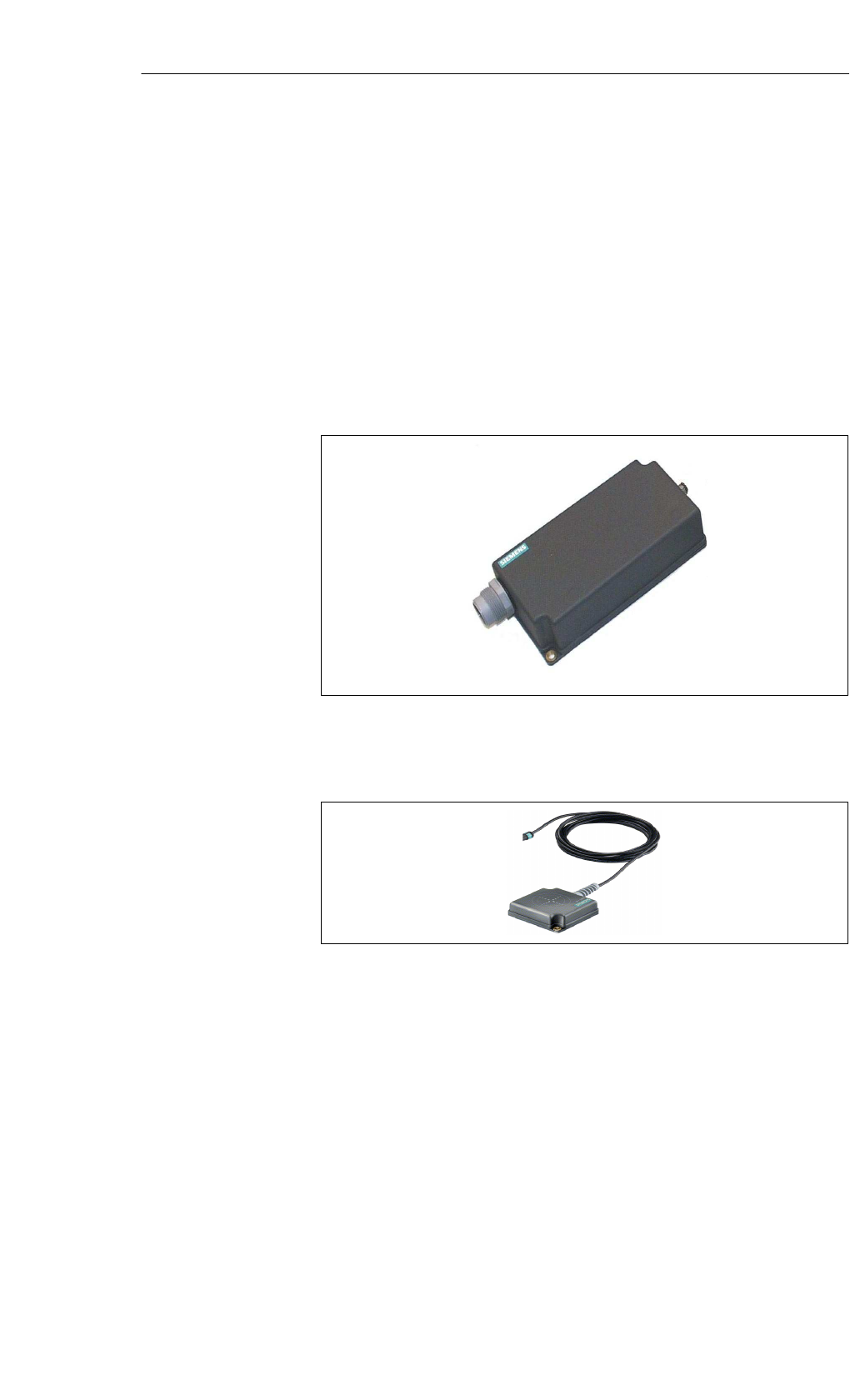
The SLG 75 ANT is a read/write device in the middle of the performance
range. It can only be used with ANT 1, ANT 12, ANT 18 and ANT 30. The
antennas can be very easily positioned for any application.
The cable between the antenna and evaluation unit is 3 m long. The length
cannot be changed.
The antenna cable can be connected on the SLG side.
The SLG 75 can be used with the following interface modules:
ASM 400, ASM 410, ASM 424, ASM 450, ASM 452, ASM 454, ASM 470,
ASM 473 und ASM 475.
Figure 5-16 Read/write device SLG 75
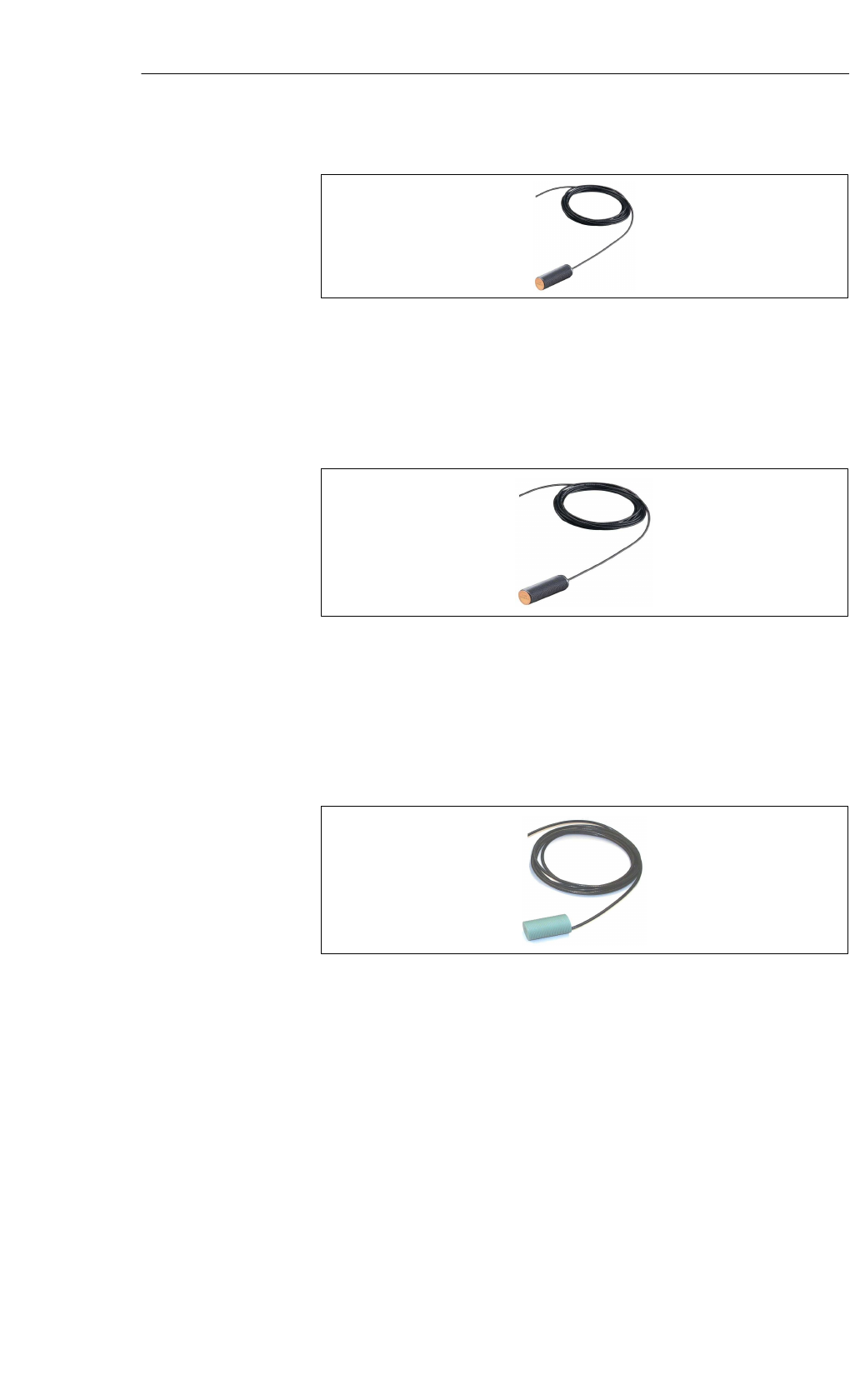
ANT 1
Figure 5-17 ANT 1 for SLG 75
The ANT 1 is an antenna in the middle of the performance range which is
very useful in production plants and assembly lines because of its easily han-
dled housing.
The antenna’s dimensions make it possible to read/write large volumes of
data from/to the MDS during operation. The antenna cable can be connected
on the SLG side.
Application
area SLG 75
Areas of
application
of the antennas
Read/Write Devices – Read/Write Antennas
5-16 MOBY E Configuration, Installation and Service Manual
(4) J31069-D0105-U001-A5-7618
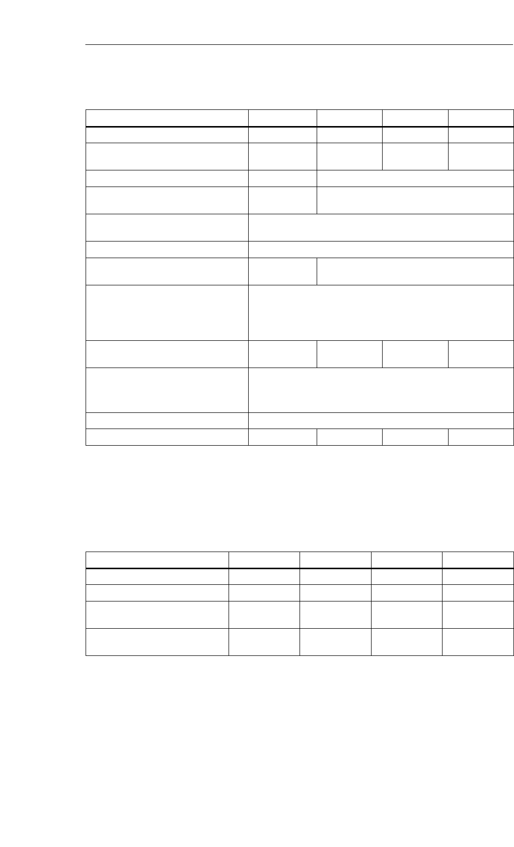
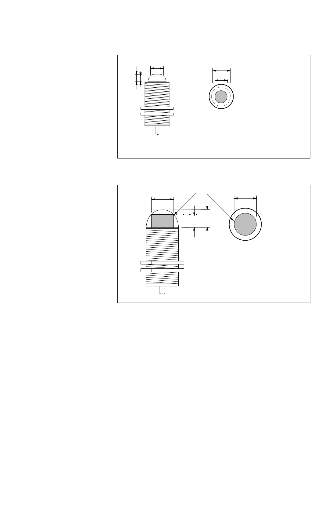
ANT 12
Figure 5-18 ANT 12 for the SLG 75
The ANT12 is intended primarily for tool identification. The very small size of
the antenna permits very accurate positioning using the plastic nuts included
with it. The antenna cable can be connected on the SLG side. Data carrier com-
munication is only possible with the MDS E623 (tool pill) in static mode.
ANT 18
Figure 5-19 ANT 18 for the SLG 75
The ANT 18 was designed primarily for use in small assembly lines. The small,
compact dimensions of the antenna with its two plastic nuts (included with the
product) make it easy to position for any application. The antenna cable can be
connected on the SLG side. Data carrier communication is only possible with
the MDS E624 in static mode.
ANT 30
Figure 5-20 ANT 30 for the SLG 75
The ANT 30 was designed primarily for use in small assembly lines. The
maximum read/write range is approximately 60% greater than the ANT 18.
The compact dimensions of antenna with its two plastic nuts (included with
the product) make it very easy to position for any application. The antenna
cable can be connected on the SLG side. Data carrier communication is only
possible with the MDS E624 in static mode.
Read/Write Devices – Read/Write Antennas

5-17
MOBY E Configuration, Installation and Service Manual
(4) J31069-D0105-U001-A5-7618
Table 5-11 Ordering data for the SLG 75 and ANT xx
SLG 75 write/read device
with RS 422 serial interface
The antenna is not included with the
SLG 75 and must be ordered separately.
6GT2 398-1AF00
Antennas:
ANT 1 75 x 75 x 20 (L x W x H)
ANT 12 M12 x 1.0 x 40 (∅ x wght x L)
ANT 18 M18 x 1.0 x 55 (∅ x wght x L)
ANT 30 M30 x 1.5 x 58 (∅ x wght x L)
6GT2 398-1CB00
6GT2 398-1CC00
6GT2 398-1CA00
6GT2 398-1CD00
SLG connector and plug-in line See Section 3.7
Table 5-12 Technical data of the SLG 75
(read/write device) SLG 75
Inductive interface to MDS
ANT-MDS read/write distances See field data
Transmission frequency 13.56 MHz
Serial interface to ASM RS 422
Data transmission speed 19200 Baud
Line length (ASM - SLG), max.
(for 24 VDC and a cross-section of
0.2 mm2)
120 m
Max. data cable length.
(See cable configuration in Table 3-13.) 1000 m
MDS addressing
command Direct access via addresses
Initialize MDS, read data from MDS,
write data to MDS
Supply voltage (via serial interface)
Nominal value
Permissible range 24 VDC
20 to 30 VDC
Current consumption
Switch-on current (brief)
Operation (at 24 VDC) Max. of 700 mA
180 mA (typical)
MTBF (at +40° C) 2.5 x 10⁵ hours
Housing
Dimensions (in mm)
Electronics w/o connectors (L x W x H) 160 x 80 x 40
Color
Material
Connector
Data
Anthracite
Plastic (PA 12)
6-pin SLG connector in accordance with
DIN 43 651 (pin, device side)
Ordering data
Technical data
Read/Write Devices – Read/Write Antennas

5-18 MOBY E Configuration, Installation and Service Manual
(4) J31069-D0105-U001-A5-7618
Table 5-12 Technical data of the SLG 75
(read/write device) SLG 75
Protection rating in accordance with
EN 60 529
Shock in accordance with
EN 60 721-3-7/class 7M2
Vibration in accordance with
EN 60 721-3-7/class 7M2
IP 65
30 g1
1 g (3 to 200 Hz)1
1.5 g (200 to 500 Hz)1
Mounting of SLG
Tightening torque at room temperature
2 M5 screws
3 Nm
Ambient temperature
During operation
During transportation and storage –25 °C to + 70 °C
–40 °C to + 85 °C
Weight (approx.) 520 g
Certification CE, UL/CSA, FCC
1Warning: The values for shock and vibration are maximum values and must
not occur continuously.
Read/Write Devices – Read/Write Antennas
5-19
MOBY E Configuration, Installation and Service Manual
(4) J31069-D0105-U001-A5-7618
Table 5-13 Technical data of the antennas
Antenna ANT 1 ANT 12 ANT 18 ANT 30
Write/read distance, max. ANT-MDS (Sg) 100 mm 5 mm 15 mm 24 mm
Housing, dimensions in mm 75 x 75 x 20
(L x W x H) M12 x 1.0 x 40
(∅ x wght x L) M18 x 1.0 x 55
(∅ x wght x L) M30 x 1.5 x 58
(∅ x wght x L)
Color Anthracite Pastel turquoise
Material Plastic (PA 12) Plastic
Crastin
Connector 4-pin
pin, antenna side
Antenna line length 3 m
Protection rating in accordance with
EN 60 529 IP 67 IP 67 (front)
Shock in accordance with
EN 60 721-3-7/class 7M2
Vibration in accordance with
EN 60 721-3-7/class 7M2
30 g 1
1 g (3 to 200Hz)1
1.5 g (200 to 500 Hz)1
Mounting of antenna 2 M5 screws 2 plastic nuts
M12 x 1.0 2 plastic nuts
M18 x 1.0 2 plastic nuts
M30 x 1.5
Ambient temperature
During operation
During transportation and storage
–25 °C to +70 °C
–40 °C to +85 °C
MTBF (at +40 °C) 2.5 x 10⁵ hours
Weight (approx.) 80 g 45 g 120 g 150 g
1Warning: The values for shock and vibration are maximum values and must not occur continuously.
Table 5-14 Field data of the SLG 75 with antenna
SLG 75 ANT 1 ANT 12 ANT 18 ANT 30
Working distance (Sa) 0 to 70 mm 0 to 4 mm 0 to 8 mm 0 to 18 mm
Limit distance (Sg) 100 mm 5 mm 15 mm 24 mm
Diameter of the transmission window
(Ld)Depends on
MDS 8 mm Depends on
MDS 14 mm
Minimum distance from SLG to
SLG (D)
800 mm 80 mm 125 mm 200 mm
Field data
Read/Write Devices – Read/Write Antennas
5-20 MOBY E Configuration, Installation and Service Manual
(4) J31069-D0105-U001-A5-7618
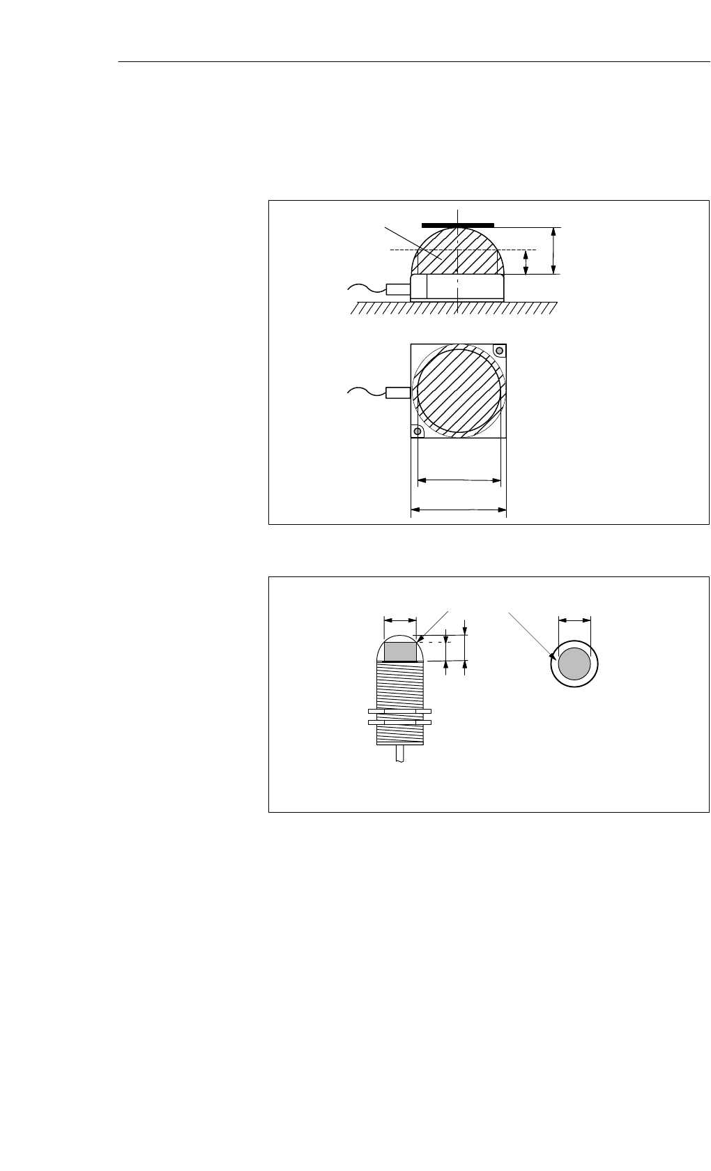
Transmission window:
The antenna of the MDS must be positioned inside this field to ensure
reliable data communication.
SgSide view
Transmission window MDS
Top view
Sa
1 The transmission window can
be larger at Sa, min.
L (Sa,min)1
L (Sa,max) = Ld
Figure 5-21 Transmission window of the ANT 1
Ld
Top view
sg
sa
Side view
Ld
Transmission window
Figure 5-22 Transmission window of the ANT12
Transmission
window
Read/Write Devices – Read/Write Antennas
5-21
MOBY E Configuration, Installation and Service Manual
(4) J31069-D0105-U001-A5-7618
Ld
Top view
Ld
sg
sa
Side view 1 The transmission window can
be larger when Sa, min
L (Sa, min)1
Figure 5-23 Transmission window of the ANT18
Ld
Top view
sg
sa
Side view
Ld
Transmission window
Figure 5-24 Transmission window of the ANT 30
Read/Write Devices – Read/Write Antennas
5-22 MOBY E Configuration, Installation and Service Manual
(4) J31069-D0105-U001-A5-7618
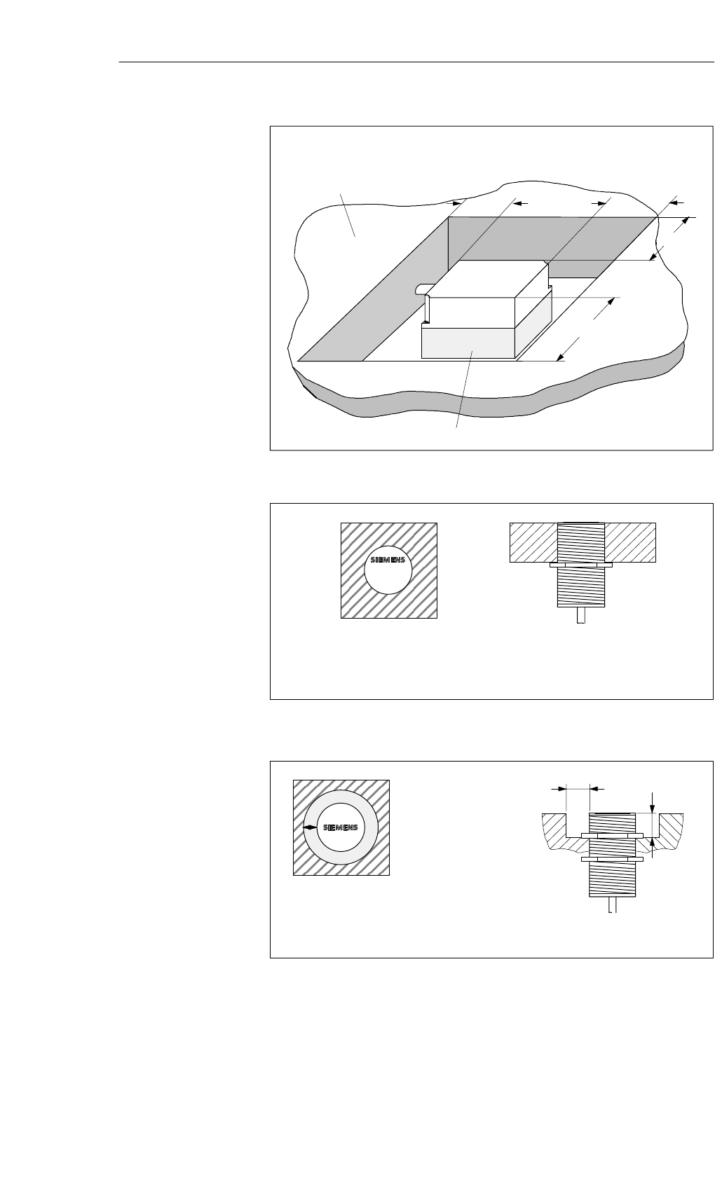
Metal-free space with flush mounting
a = 40 mm
a
Metal
a
a
a
h = 20 mm (non-metallic base)
Figure 5-25 Metal-free space for the ANT 1
Note:
Flush installation in metal reduces the limit
and working distance.
Top view Side view
MOBYE
ANT 12
Figure 5-26 Metal-free space for the ANT12
aMOBY E
ANT 18
a = 10 mm
b = 10 mm
Metal-free space with flush
installation
Note:
The limit and working distances are
reduced when the metal-free space is
not adhered to.
10
10
ANT 18
Figure 5-27 Metal-free space for the ANT 18
Metal-free space
Read/Write Devices – Read/Write Antennas
5-23
MOBY E Configuration, Installation and Service Manual
(4) J31069-D0105-U001-A5-7618
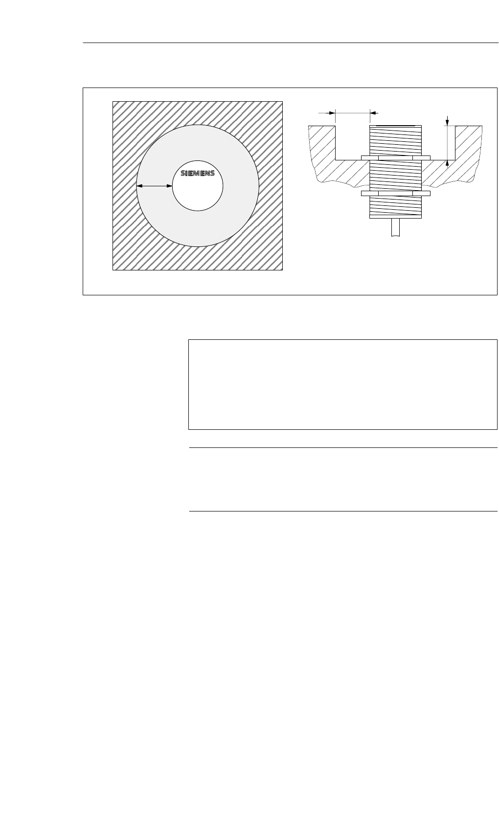
MOBYE
ANT 30
20
Side view
20
20
Top view
Figure 5-28 Metal-free space for the ANT 30
Made in Germany
SIEMENS MOBY E SLG 75
FCC ID: NXWMOBYE-SLG75
THIS DEVICE COMPLIES WITH PART 15 OF THE FCC RULES: OPERATION IS SUBJECT TO
THE FOLLOWING TWO CONDITIONS:
(1) THIS DEVICE MAY NOT CAUSE HARMFUL INTERFERENCE, AND (2) THIS DEVICE MUST
ACCEPTANYINTERFERENCERECEIVED; INCLUDING INTERFERENCE THATMAYCAUSE
Note
The manufacturer is not responsible for any radio or TV interference caused
by unauthorized modifications to this equipment:
Such modifications could void the user’s authority to operate the equipment.
FCC information
Read/Write Devices – Read/Write Antennas
UNDESIRED OPERATION.
5-24 MOBY E Configuration, Installation and Service Manual
(4) J31069-D0105-U001-A5-7618
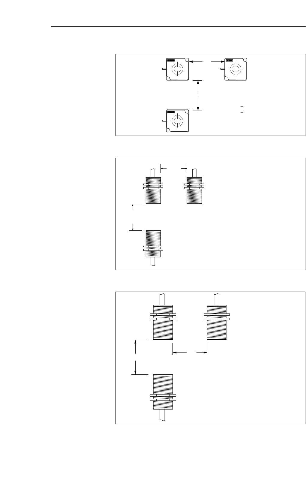
Da
Db
ANT 1ANT 1
ANT 1
Da> 800 mm
Db> 800 mm
Figure 5-29 Distance D: ANT 1
Da 80 mm
Db 80 mm
The SLG electronics can be
mounted directly next to each other.
Db
Da
Figure 5-30 Distance D: ANT 12
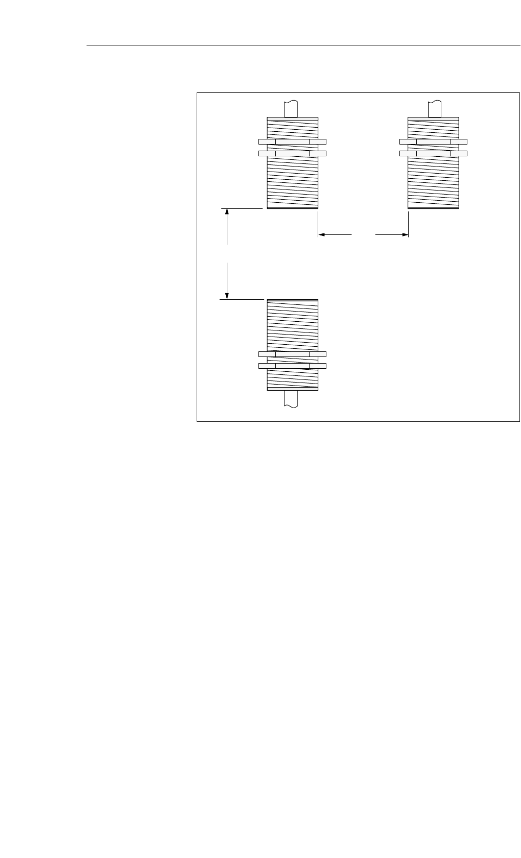
Da 125 mm
Db 125 mm
The SLG electronics can be
mounted directly next to each other.
Db
Da
Figure 5-31 Distance D: ANT 18
Definition of
the distance D
Read/Write Devices – Read/Write Antennas
5-25
MOBY E Configuration, Installation and Service Manual
(4) J31069-D0105-U001-A5-7618
Da 200 mm
Db 200 mm
The SLG electronics can be
mounted directly next to each other.
Db
Da
Figure 5-32 Distance D: ANT 30
Read/Write Devices – Read/Write Antennas
5-26 MOBY E Configuration, Installation and Service Manual
(4) J31069-D0105-U001-A5-7618
5.5
5
5
80 40
160
25
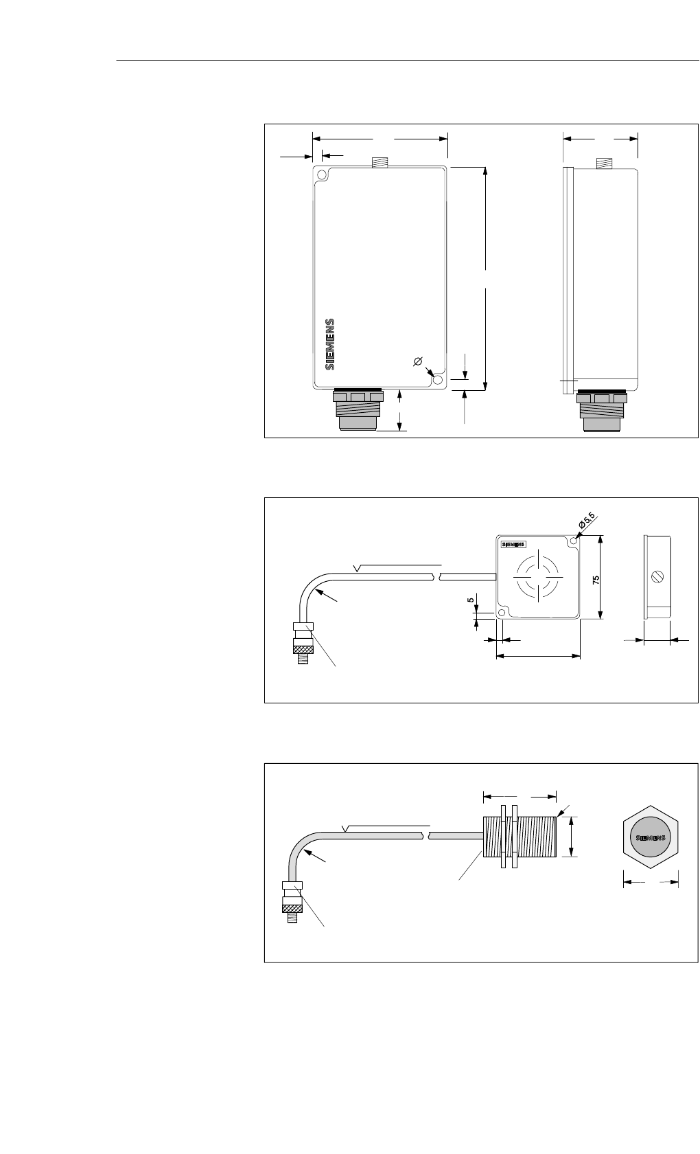
Figure 5-33 Dimensioned drawing of SLG 75
5 20
75
Minimum bending
radius: 20 mm
Cable length 3 m
ANT 1 can be connected
on electronics side
Figure 5-34 Dimensioned drawing of the ANT 1
40
M12
Fine thread
Gradient 1.0
Minimum bending
radius: 20 mm
Cable length 3 m
ANT 12 can be connected
on electronics side
Antenna
head
Antenna
side
Side view
of the antenna
head
17
MOBY E
ANT 12
Figure 5-35 Dimensioned drawing of the ANT 12
Dimensions
(in mm)
Read/Write Devices – Read/Write Antennas
5-27
MOBY E Configuration, Installation and Service Manual
(4) J31069-D0105-U001-A5-7618
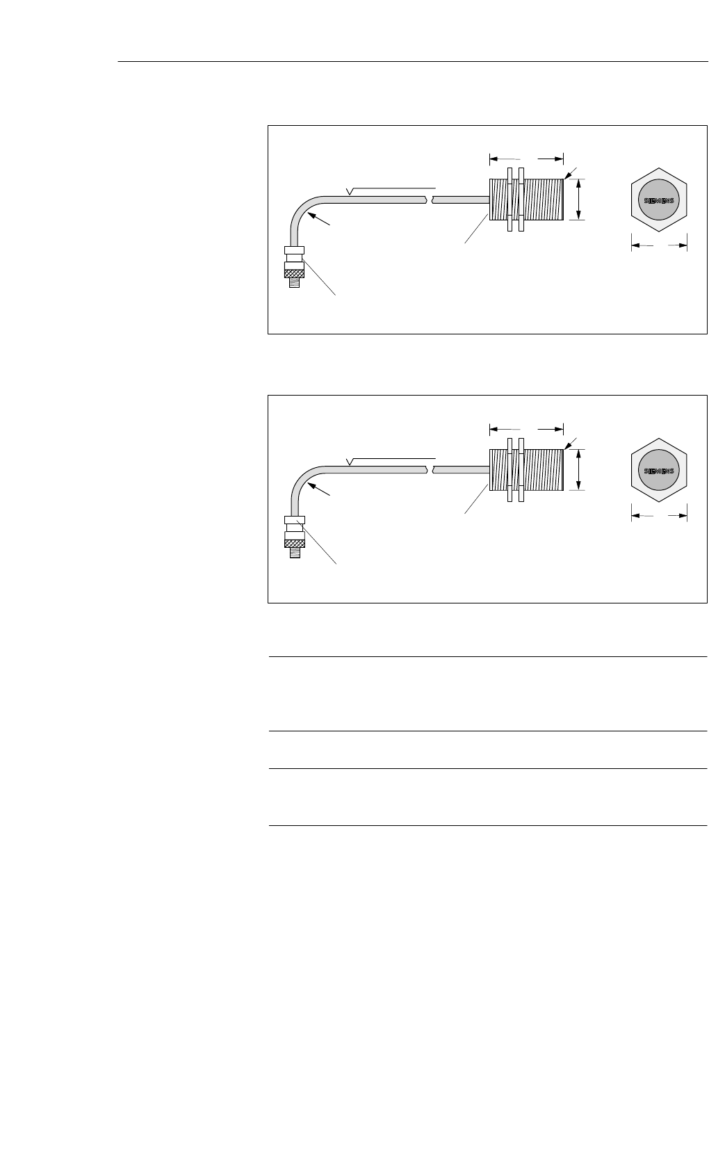
55
M18
Fine thread
Gradient 1.0
Minimum bending
radius: 20 mm
Cable length 3 m
ANT 18 can be connected
on electronics side
Antenna
head
Antenna
side
Side view
of the antenna
head
24
MOBY E
ANT 18
Figure 5-36 Dimensioned drawing of the ANT 18
58
M30
Fine thread
incline: 1.5
Minimum bending
radius: 20 mm
Cable length 3 m
ANT 30 can be
connected on electronics side
Antenna
head
Antenna
side
Side view
of the antenna
head
43
MOBY E
ANT 30
Figure 5-37 Dimensioned drawing of the ANT 30
Note
The length of the line between antenna and evaluation unit is 3 m. The
length cannot be changed.
Caution
The antenna must not be removed in an energized state.
Read/Write Devices – Read/Write Antennas