Siemens MOBYI-SLG40N Tag Reader System User Manual MOBY I e
Siemens AG Tag Reader System MOBY I e
UserManual.wiki
>
Siemens
>
MOBYI-SLG40N User Manual
>
Users Manual Part 3
Contents
1.
Users Manual Part 1
2.
Users Manual Part 2
3.
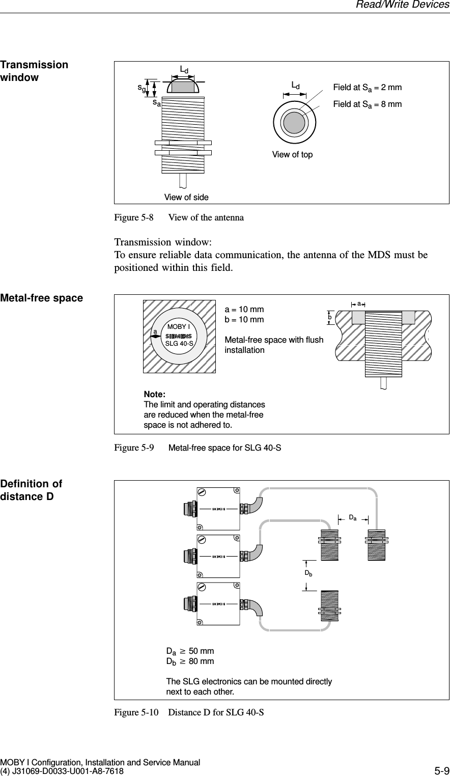
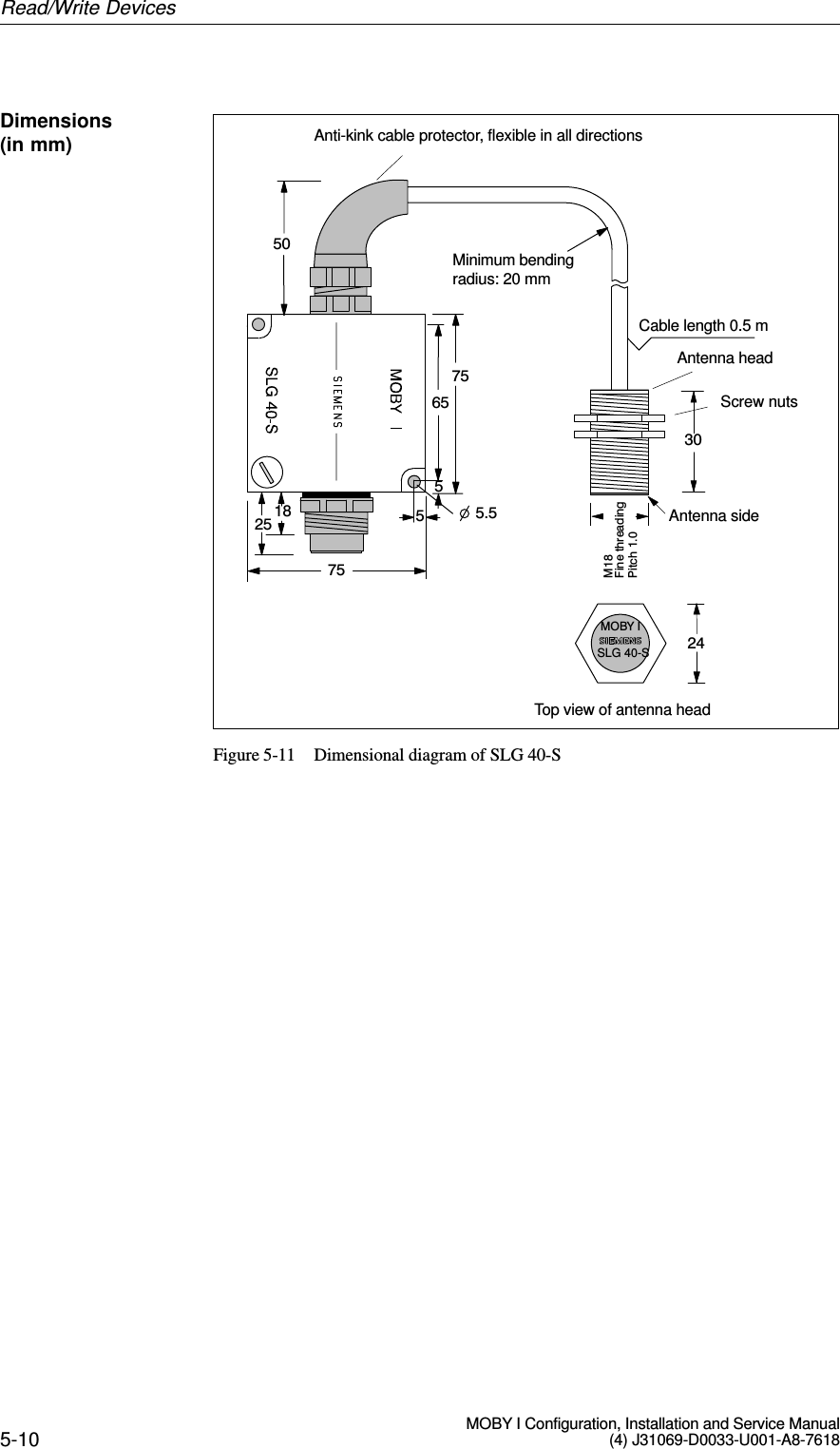
Users Manual Part 3
Users Manual Part 3
Navigation menu
Upload a User Manual
Namespaces
Wiki Guide
HTML
PDF
Info
Views
User Manual
Discussion / Help
Navigation