Siemens MOBYI-SLG40N Tag Reader System User Manual MOBY I e
Siemens AG Tag Reader System MOBY I e
Siemens >
Contents
- 1. Users Manual Part 1
- 2. Users Manual Part 2
- 3. Users Manual Part 3
Users Manual Part 3
5-1
MOBY I Configuration, Installation and Service Manual
(4) J31069-D0033-U001-A8-7618
Read/Write Devices 5
5-2 MOBY I Configuration, Installation and Service Manual
(4) J31069-D0033-U001-A8-7618
5.1 Introduction
The read/write devices (i.e., SLGs) provide inductive communication with
the mobile data memories (i.e., MDSs) and the serial link to the interfaces
(i.e., ASMs).
Various SLG models – for short, medium and long distances to the MDS –
are available to meet customer requirements.
The SLG executes commands received from the interface. These commands
for reading and writing data are converted via a modulator/demodulator cir-
cuit.
Communication between MDS and SLG takes place via inductive alternating
fields.
The amount of data which can be transferred between SLG and MDS de-
pends on the factors listed below.
SThe speed at which the MDS moves through the transmission window of
the SLG
SThe length of the transmission window
SThe type of MDS (i.e., RAM, FRAM, EEPROM)
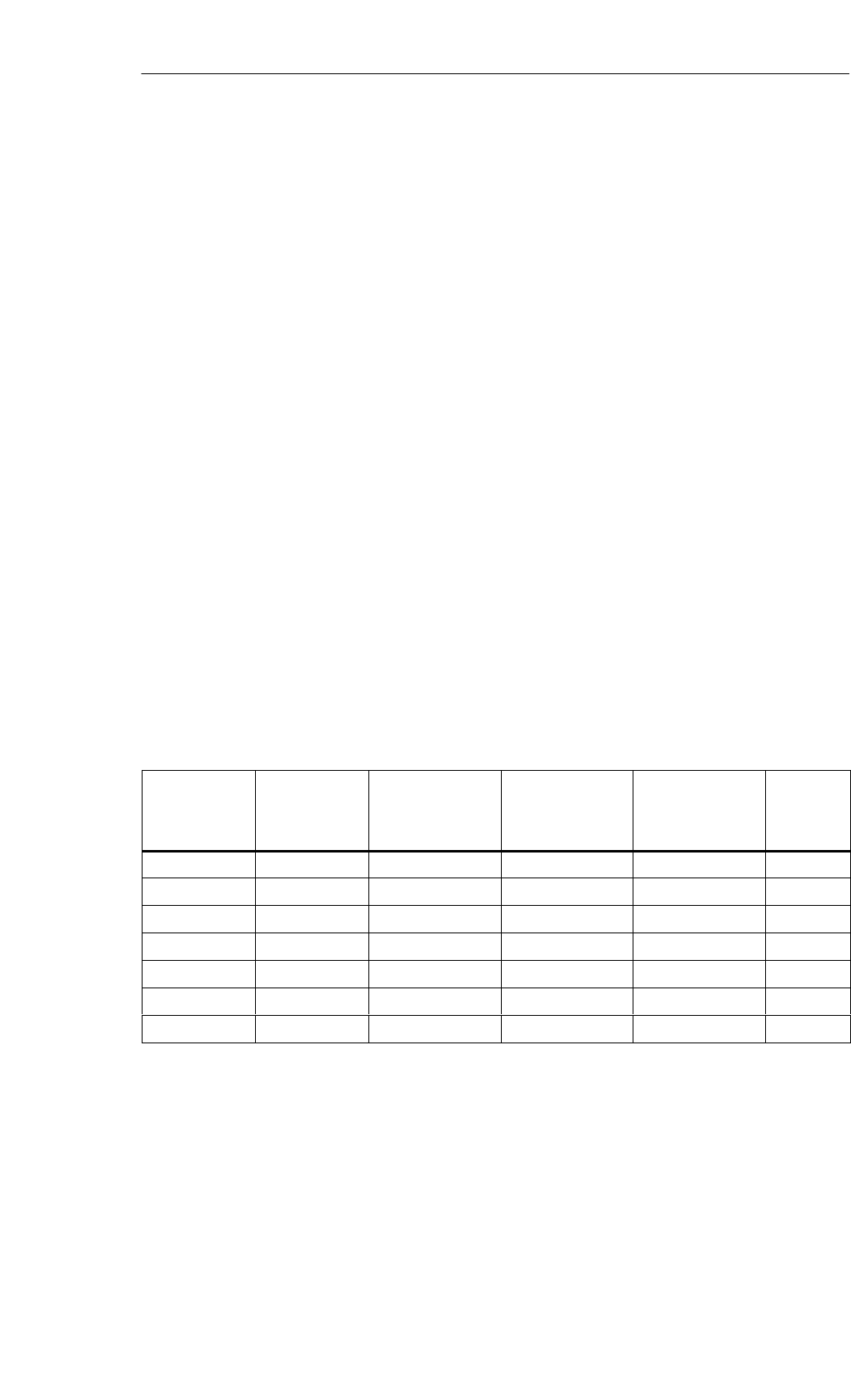
Table 5-1 Overview table of the SLG
SLG Type Operating
Distance Sa
(Depending on
MDS)
Limit Distance SgTemperature
Range
(During
Operation)
Dimensions
(WxHxD) in mm
Protection
Rating
SLG 40 2 to 8 mm 10 mm –25 to +70° C∅ 30 x 54 (head) IP65
SLG 40-S 2 to 6 mm 8 mm –25 to +70° C∅ 18 x 30 (head) IP65
SLG 41/41-S 0 to 15 mm 25 mm –25 to +70° C 120 x 40 x 40 IP65
SLG 41C/41CC 0 to 15 mm 25 mm –25 to +70° C 55 x 75 x 30 IP67
SLG 42 0 to 55 mm 70 mm –25 to +70° C 75 x 40 x 75 IP65
SLG 43 0 to 100 mm 150 mm –25 to +70° C 238 x 40 x 80 IP65
SLG 44 100 to 800 mm 1000 mm –25 to +70° C 238 x 40 x 80 IP63
Application area
Layout and func-
tions
Overview table
Read/Write Devices
5-3
MOBY I Configuration, Installation and Service Manual
(4) J31069-D0033-U001-A8-7618
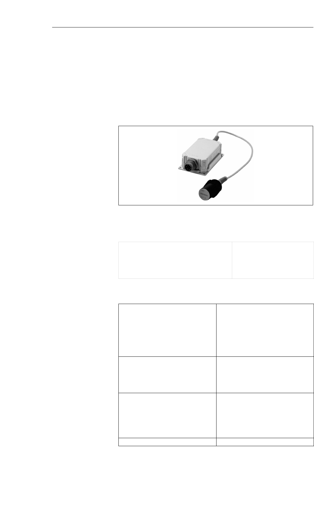
5.2 SLG 40
The SLG 40 is extremely suited for use on small assembly lines. The short
installation distance between several SLG 40 antennas is a special feature.
With the 2 included screw nuts, the antenna head can be positioned with ex-
treme precision for each application.
Figure 5-1 Read/write device SLG 40
Table 5-2 Ordering data for SLG 40
Read/write device SLG 40
up to 10 mm (low power), incl. screw nuts
Accessories:
SLG plug connector and stub lines
Mounting clamp
6GT2 001-0EA10
See chapter 3.10
3SX6 284
Table 5-3 Technical data of SLG 40
Inductive interface to MDS
Data transmission speed
Read/write distance
SLG to MDS (max.)
Transmission frequency
SPower
SData
19200 baud
10 mm (see field data table)
134 kHz
1.81 MHz
Serial interface to ASM
Transmission speed
Line length, ASM to SLG (max.)
at 24 V DC
6-pin SLG plug connector in acc. w.
DIN 43651
19200 baud, RS 422
360 m
Supply voltage
(via serial interface)
Nominal value
Permissible range
Current consumption
Idle/operation
24 V DC
20 to 30 V DC
25 mA/90 mA
MTBF 2 x 10⁶
Application area
Ordering data
Technical data
Read/Write Devices
5-4 MOBY I Configuration, Installation and Service Manual
(4) J31069-D0033-U001-A8-7618
Table 5-3 Technical data of SLG 40
Housing
Dimensions (in mm)
For antenna head (∅ x threading x L)
For electronics w/o plug (WxHxD)
Color Antenna
SLG housing
Material Antenna
SLG housing
Plug connection
M30 x 1.5 x 54
125 x 40 x 75
Anthracite with orange head
Ergo-gray
“Crastin”
Polyamide 12
DIN 43651
Protection rating
Antenna and SLG housing
Shock
Vibration
IP65
50 g
20 g
Mounting of SLG
Turning moment (at room temperature)
4 M5 screws
v 2 Nm
Ambient temperature
During operation
During transportation and storage
–25° to +70° C
–40° to +85° C
Weight (approx.) 215 g
Certifications EN 300 330
FCC Part 15
UL/CSA
Applicable for MDS 402/401
Table 5-4 Field data of SLG 40
Operating distance (Sa) 2 to 8 mm
Limit distance (Sg) 10 mm
Median deviation (Ld) 18 mm (+ 9 mm from middle)
Minimum distance from SLG to SLG (D) Daw 50 mm
Dbw 80 mm
Made in Germany
SIEMENS MOBY I SLG 40
THIS DEVICE COMPLIES WITH PART 15 OF THE FCC RULES: OPERATION IS SUBJECT TO
THE FOLLOWING TWO CONDITIONS:
(1) THIS DEVICE MAY NOT CAUSE HARMFUL INTERFERENCE, AND (2) THIS DEVICE MUST
ACCEPT ANY INTERFERENCE THAT MAY CAUSE UNDESIRED OPERATION.
Note
The manufacturer is not responsible for any radio or TV interference caused
by unauthorized modifications to this equipment:
Such modifications could void the user’s authority to operate the equipment.
Field data
FCC information
Read/Write Devices
5-5
MOBY I Configuration, Installation and Service Manual
(4) J31069-D0033-U001-A8-7618
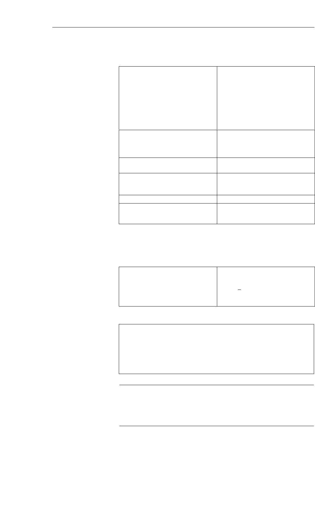
Ld
View of top
Ld
sg
sa
Field at Sa = 2 mm
Field at Sa = 8 mm
View of side
Figure 5-2 View of the antenna
Transmission window:
To ensure reliable data communication, the antenna of the MDS must be
positioned within this field. A diameter of Ld = 18 mm can be configured for
the operating distance (2 to 8 mm).
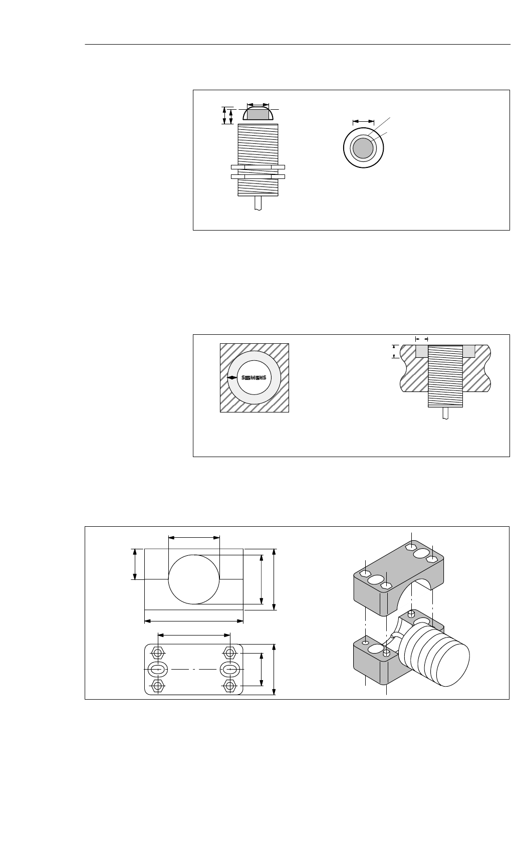
aMOBY I
SLG 40
b
a
a = 10 mm
b = 10 mm
Metal-free space with flush
installation
Note:
The limit and operating distances
are reduced when the metal-free
space is not adhered to.
Figure 5-3 Metal-free space for SLG 40
30
29
36
58
18
19,5
30
42,5
Figure 5-4 Mounting diagram and dimensions of SLG 40 with mounting clamp
Transmission
window
Metal-free space
Optional mounting
clamp
Read/Write Devices
5-6 MOBY I Configuration, Installation and Service Manual
(4) J31069-D0033-U001-A8-7618
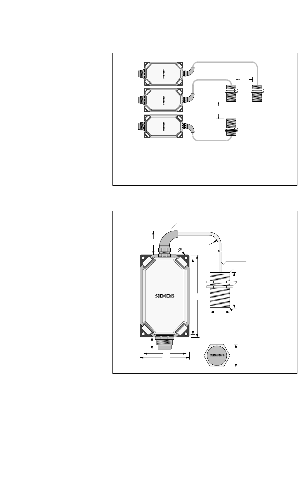
Db
Da
Daw 50 mm
Dbw 80 mm
The SLG electronics can be mounted directly
next to each other.
Figure 5-5 Distance D for SLG 40
75
65
125115
5.5
54
M30
21
40
36
MOBY I
SLG 40
MOBY I
SLG 40
Antenna head
Anti-kink cable protector, flexible
in all directions
Minimum bending
radius: 20 mm
Cable length 0.5 m
Screw nuts
Antenna side
Top view of antenna head
Figure 5-6 Dimensional diagram of SLG 40
Definition of
distance D
Dimensions
(in mm)
Read/Write Devices
5-7
MOBY I Configuration, Installation and Service Manual
(4) J31069-D0033-U001-A8-7618
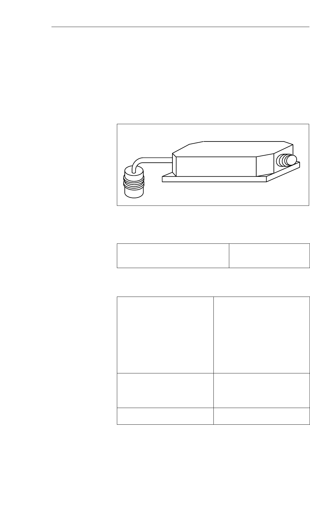
5.3 SLG 40-S
The SLG 40 is extremely suited to use in small assembly lines. The short
installation distance between several SLG 40-S antennas is a special feature.
With the 2 included screw nuts, the antenna head can be positioned with ex-
treme precision for each application.
Figure 5-7 Read/write device SLG 40-S
Table 5-5 Ordering data for SLG 40-S
Read/write device SLG 40-S
up to 8 mm (low power), incl. screw nuts
SLG plug connector and stub lines
6GT2 001-0EB00
See chapter 3.10
Table 5-6 Technical data of SLG 40-S
Housing
Dimensions (in mm)
For antenna head (∅ x threading x L)
For electronics w/o plug (L xW x H)
Color Antenna
SLG housing
Material Antenna
SLG housing
Plug connection
M18 x 1.0 x 30
75 x 75 x 40
Anthracite with orange head
Ergo-gray
“Crastin”
Polyamide 12
DIN 43651
Protection rating
Antenna and SLG housing
Shock
Vibration
IP65
50 g
20 g
Storage temperature
Operation temperature
–40° to +85° C
–25° to +70° C
Application area
Ordering data
Technical data
Read/Write Devices
5-8 MOBY I Configuration, Installation and Service Manual
(4) J31069-D0033-U001-A8-7618
Table 5-6 Technical data of SLG 40-S
Operating voltage
Current
consumption Idle
Operation
17 to 30 V DC
25 mA
90 mA
Serial interface RS 422
Transmission speed 19200 baud
Max. cable length (cf. chap. 3.10.1; stan-
dard cable)
360 m
MTBF 2 x 10⁶
Transmission frequency
SPower
SData
134 kHz
1.81 MHz
Mounting of SLG
Turning moment (at room temperature)
4 M5 screws
v 2 Nm
Mounting of SLG head (included) 2 nuts (M18 x 1.0)
Weight (approx.) 200 g
Certifications EN 300 330
FCC Part 15
UL/CSA
Applicable for MDS 401/402
Table 5-7 Field data of SLG 40-S
Operating distance (Sa) 2 to 6 mm
Limit distance (Sg) 8 mm
Diameter of transmission window (Ld) 9 mm
Median deviation " 4.5 mm from middle
Minimum distance from SLG to SLG (D) Daw 50 mm
Dbw 80 mm
Made in Germany
SIEMENS MOBY I SLG 40S
THIS DEVICE COMPLIES WITH PART 15 OF THE FCC RULES: OPERATION IS SUBJECT TO
THE FOLLOWING TWO CONDITIONS:
(1) THIS DEVICE MAY NOT CAUSE HARMFUL INTERFERENCE, AND (2) THIS DEVICE MUST
ACCEPT ANY INTERFERENCE THAT MAY CAUSE UNDESIRED OPERATION.
Note
The manufacturer is not responsible for any radio or TV interference caused
by unauthorized modifications to this equipment:
Such modifications could void the user’s authority to operate the equipment.
Field data
FCC information
Read/Write Devices
5-9
MOBY I Configuration, Installation and Service Manual
(4) J31069-D0033-U001-A8-7618
Ld
Ld
sg
sa
View of top
Field at Sa = 2 mm
Field at Sa = 8 mm
View of side
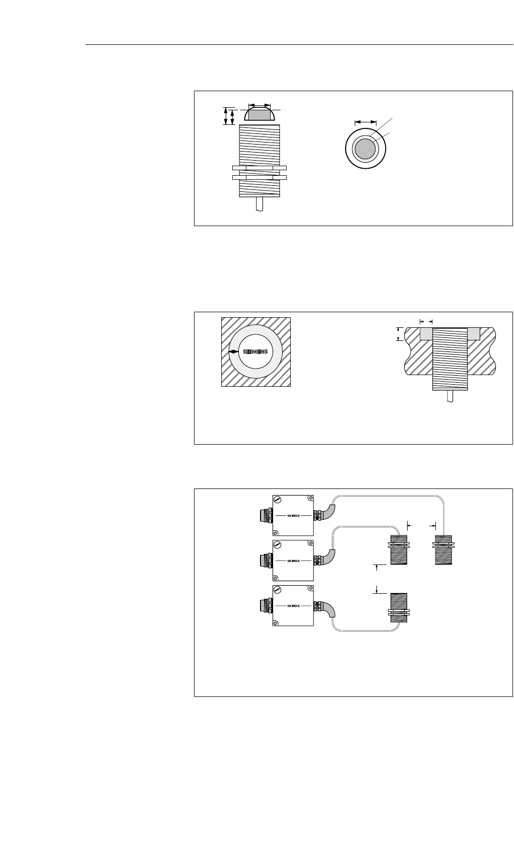
Figure 5-8 View of the antenna
Transmission window:
To ensure reliable data communication, the antenna of the MDS must be
positioned within this field.
aMOBY I
SLG 40-S
b
a
a = 10 mm
b = 10 mm
Metal-free space with flush
installation
Note:
The limit and operating distances
are reduced when the metal-free
space is not adhered to.
Figure 5-9 Metal-free space for SLG 40-S
Db
Da
Daw 50 mm
Dbw 80 mm
The SLG electronics can be mounted directly
next to each other.
Figure 5-10 Distance D for SLG 40-S
Transmission
window
Metal-free space
Definition of
distance D
Read/Write Devices
5-10 MOBY I Configuration, Installation and Service Manual
(4) J31069-D0033-U001-A8-7618
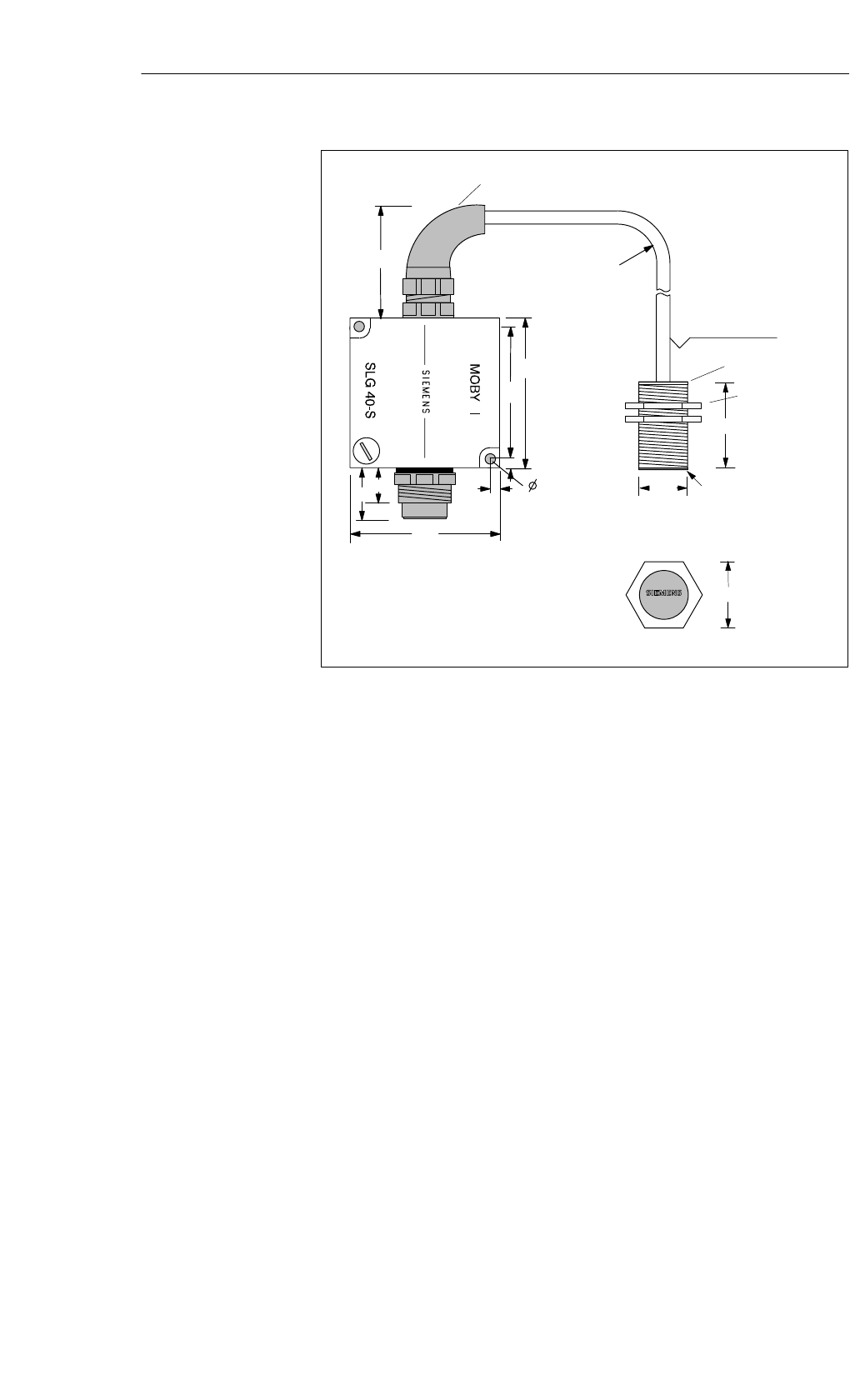
30
50
24
MOBY I
75
65
5
5
75
5.5
18
25
Antenna head
Anti-kink cable protector, flexible in all directions
Minimum bending
radius: 20 mm
Cable length 0.5 m
Screw nuts
Antenna side
Top view of antenna head
M18
Fine threading
Pitch 1.0
SLG 40-S
Figure 5-11 Dimensional diagram of SLG 40-S
Dimensions
(in mm)
Read/Write Devices