Siemens RF210R RFID Reader User Manual II
Siemens AG RFID Reader II
UserManual.wiki
>
Siemens
>
RF210R User Manual
>
user manual II
Contents
1.
user manual I
2.
user manual II
3.
user manual
user manual II
Navigation menu
Upload a User Manual
Namespaces
Wiki Guide
HTML
PDF
Info
Views
User Manual
Discussion / Help
Navigation
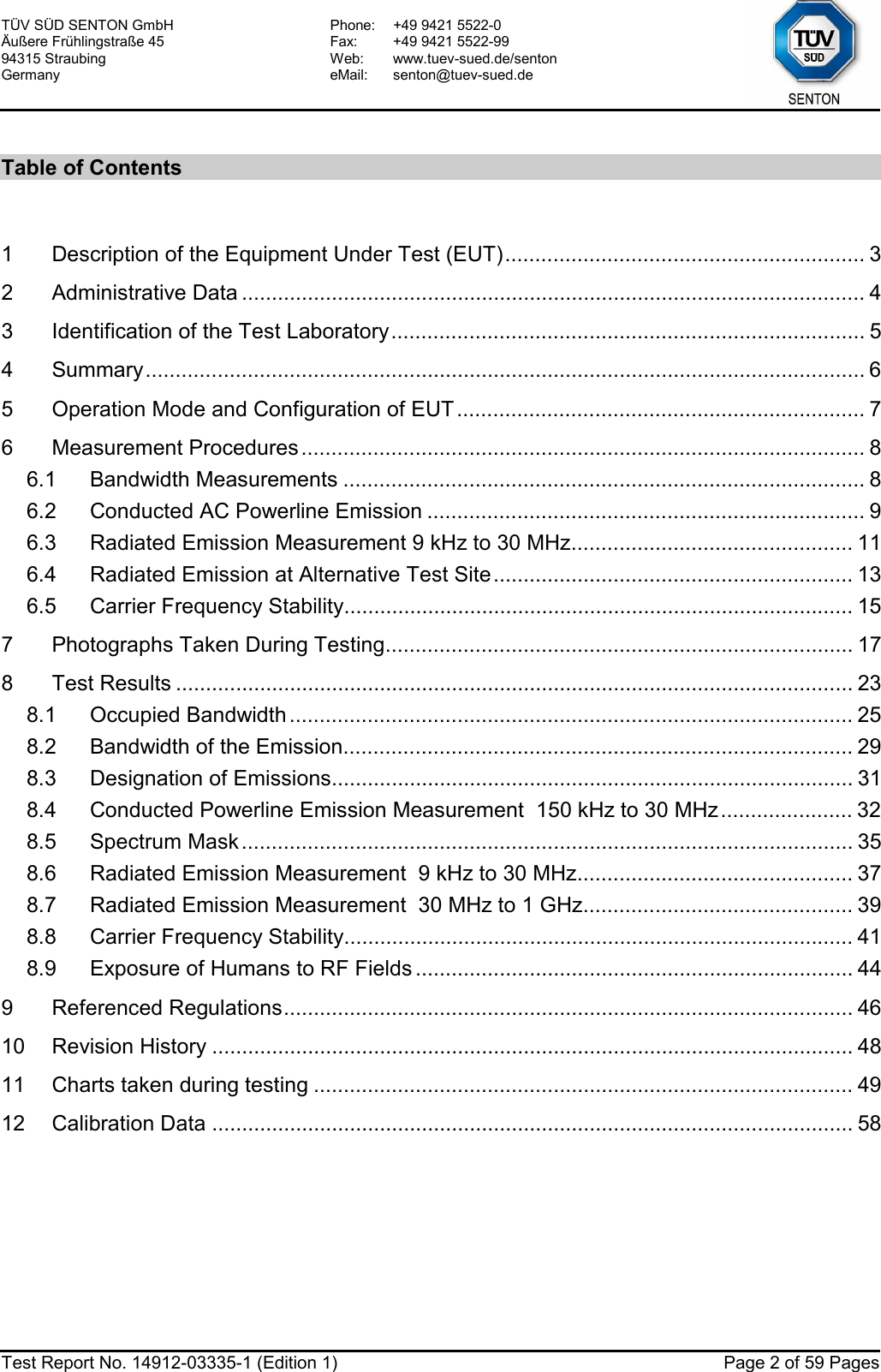
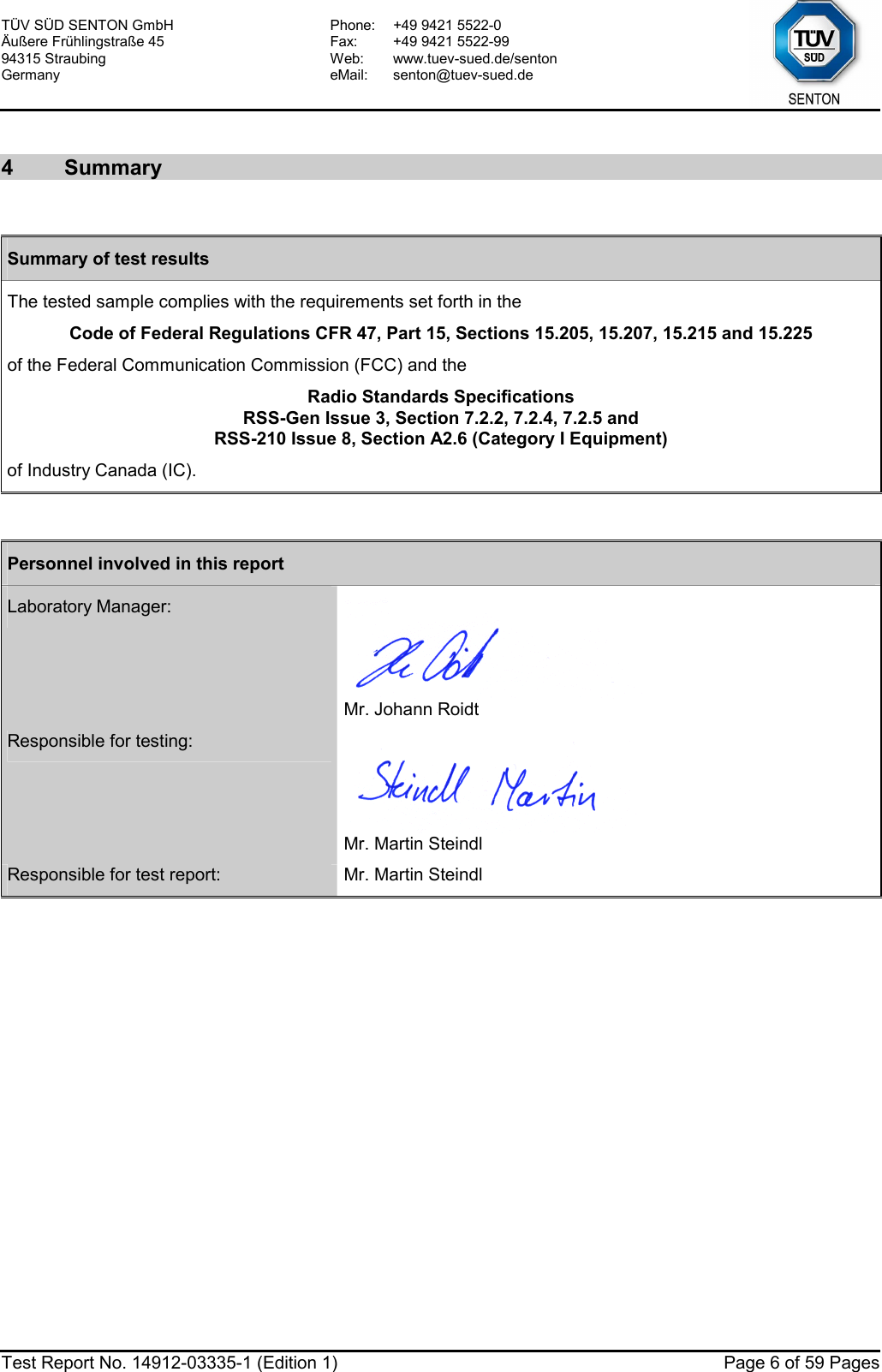
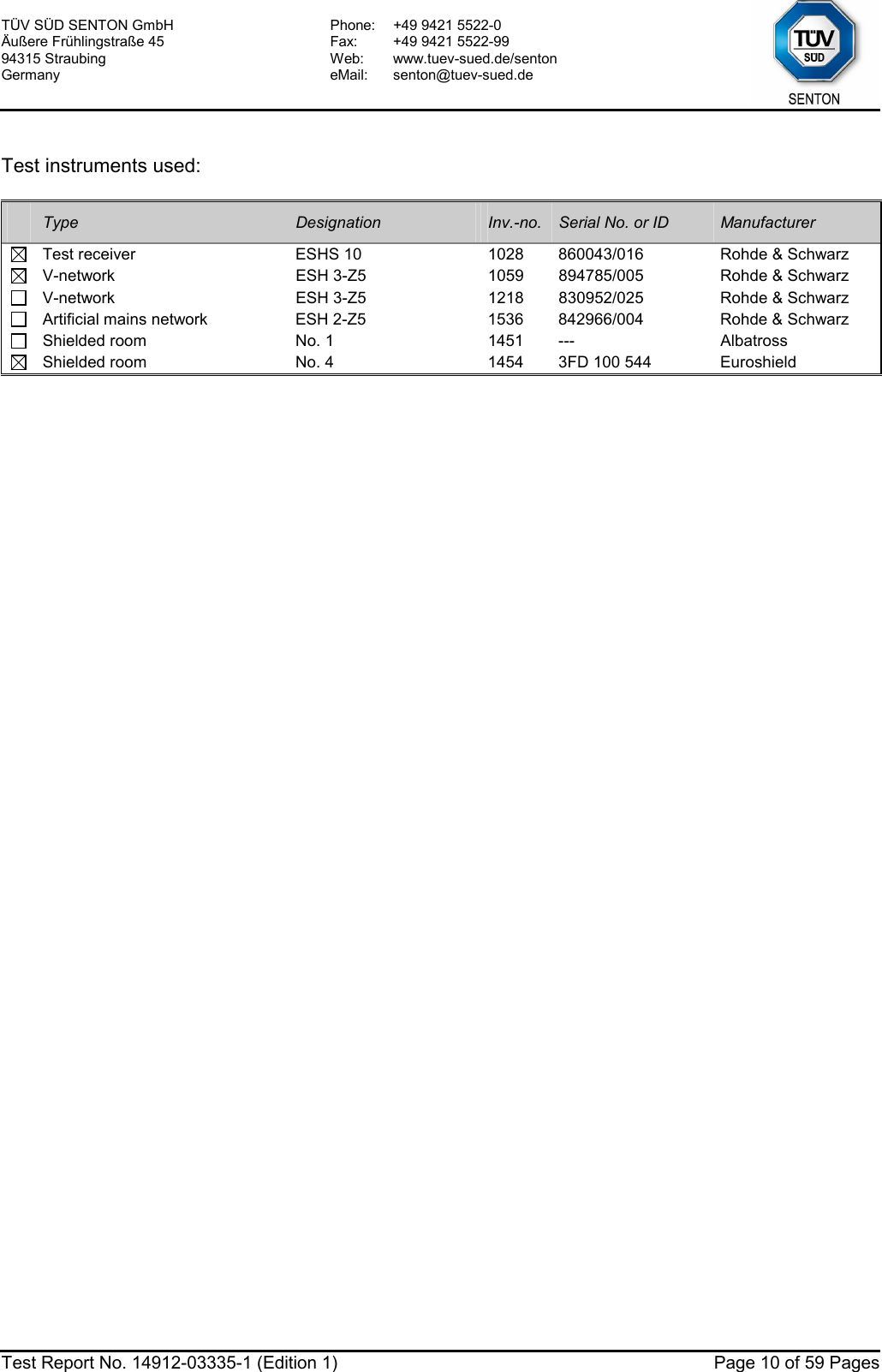
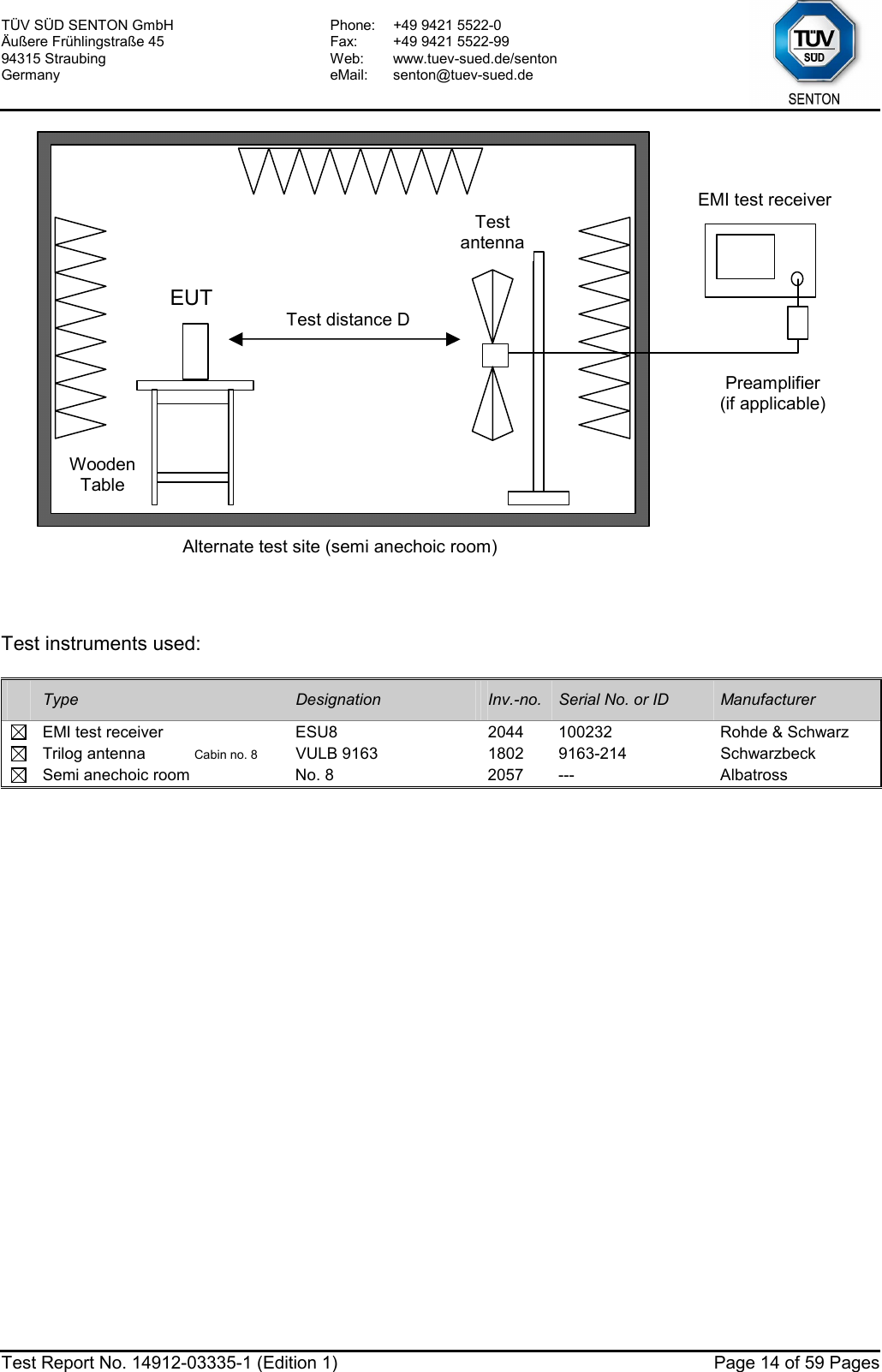
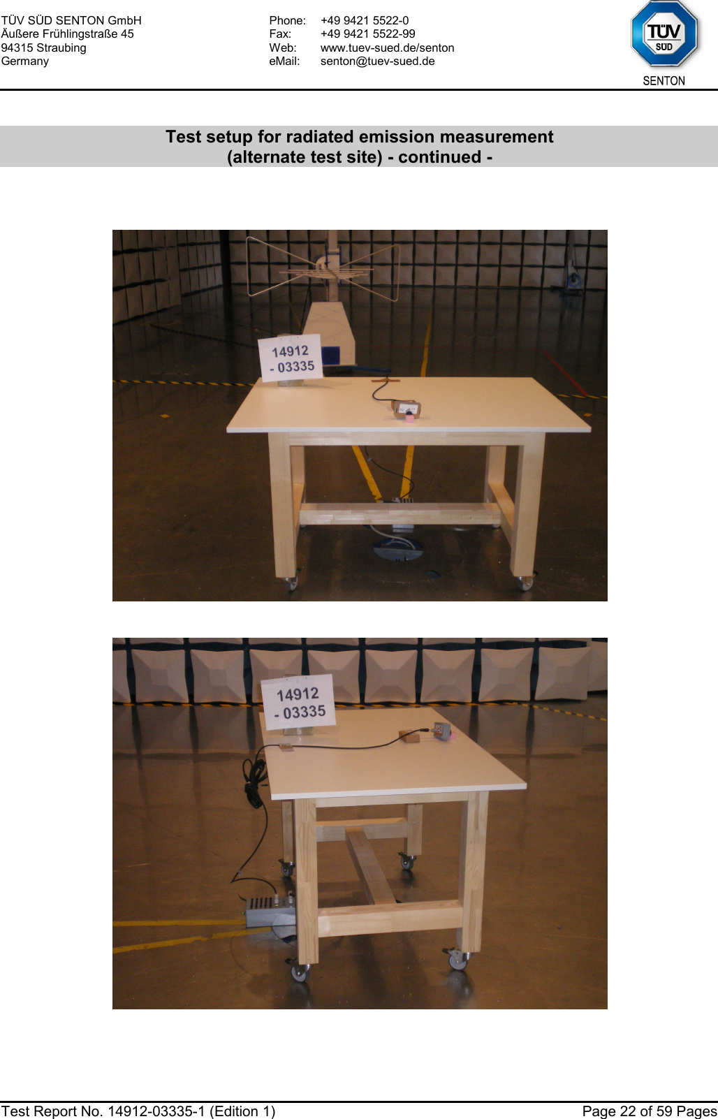
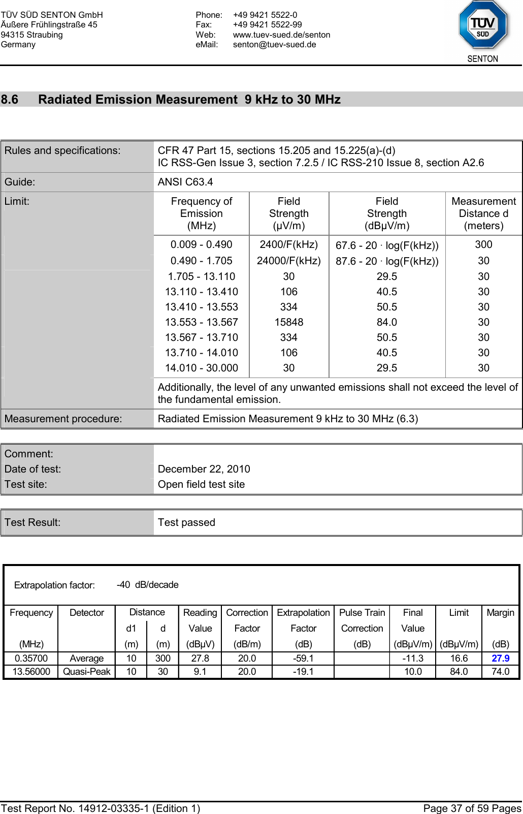
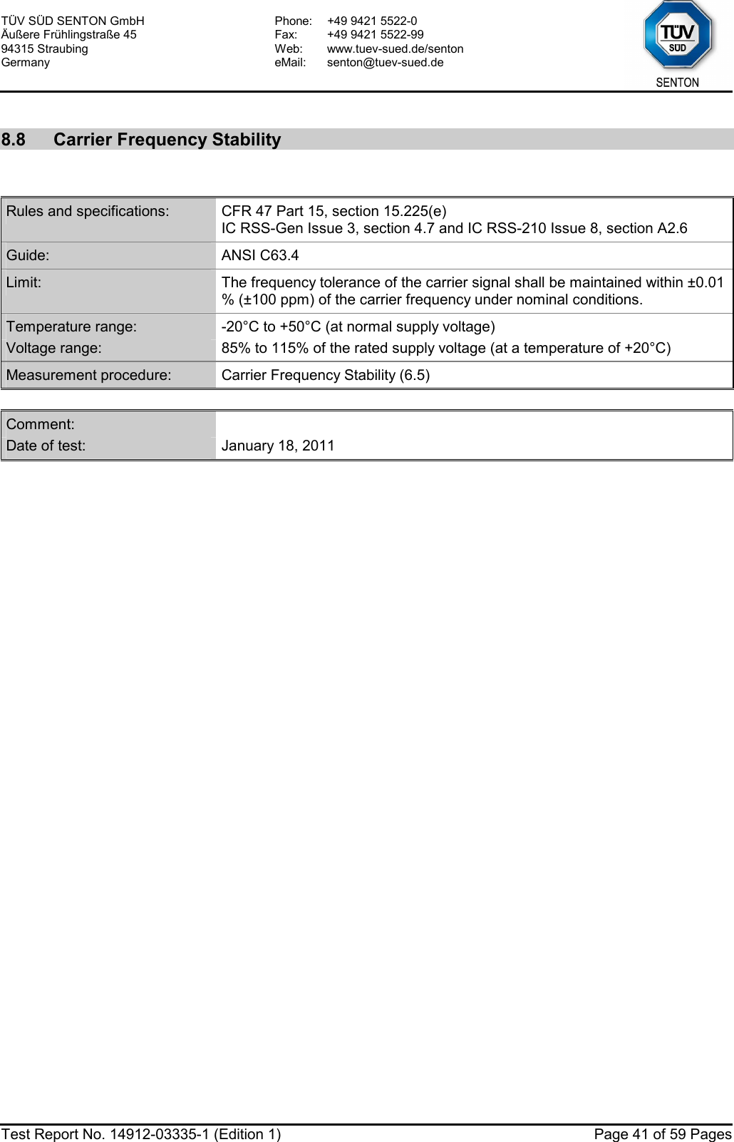
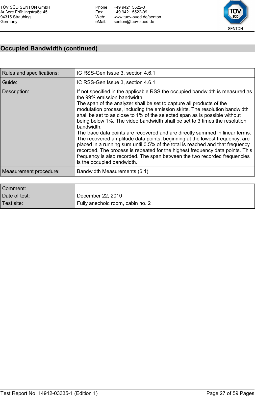
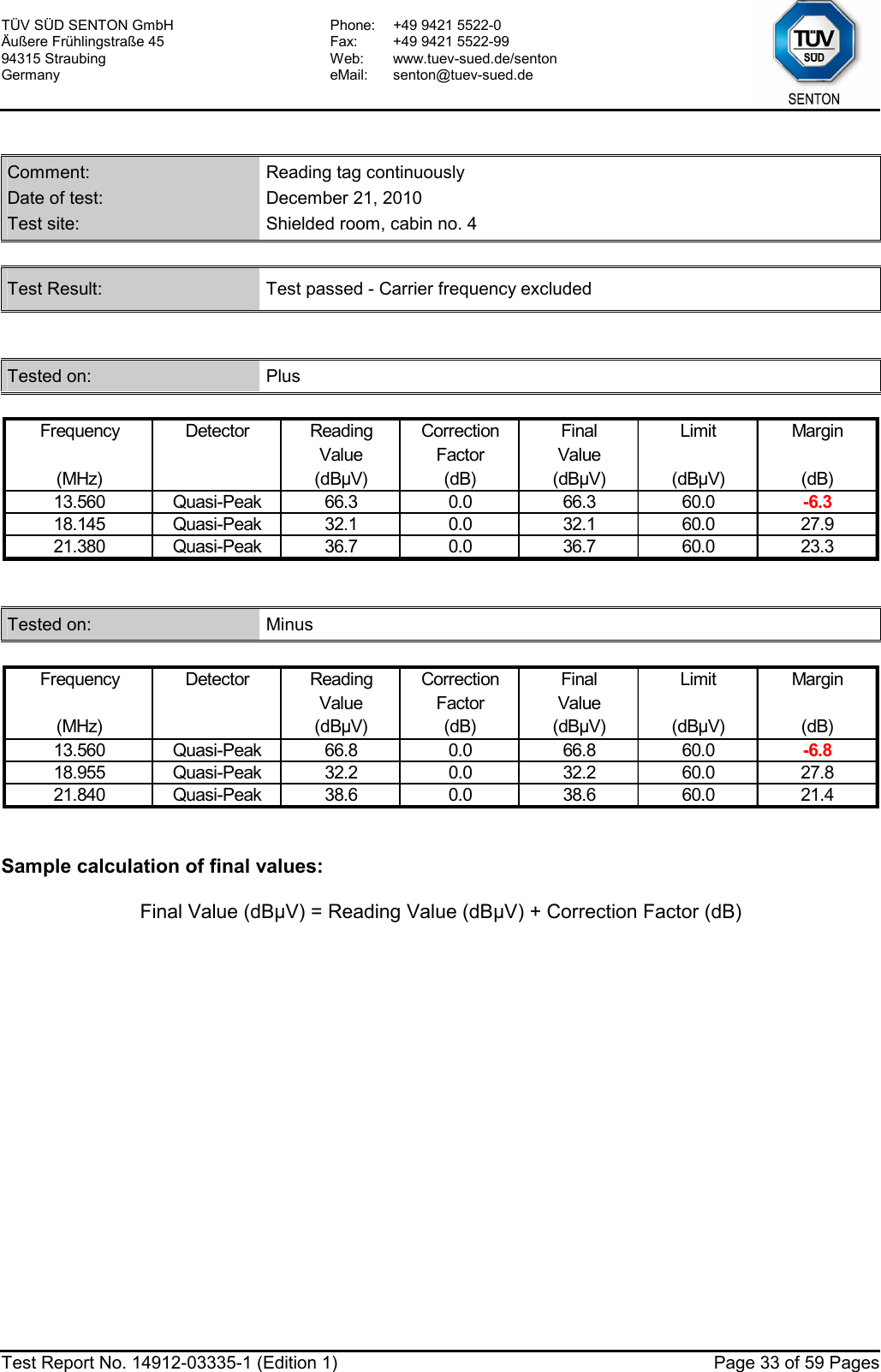
![TÜV SÜD SENTON GmbH Äußere Frühlingstraße 45 94315 Straubing Germany Phone: +49 9421 5522-0 Fax: +49 9421 5522-99 Web: www.tuev-sued.de/senton eMail: senton@tuev-sued.de Test Report No. 14912-03335-1 (Edition 1) Page 26 of 59 Pages Occupied Bandwidth (99 %): Att 0 dB** A Offset 20 dBLVLRef 70 dBµVPS 2 kHz/Center 13.55944 MHz Span 20 kHz*3DBRBW 1 kHzDCVBW 10 kHzSGLSWT 10 s**1 RMCLRWR-30-20-100102030405060701Marker 1 [T1 ] 39.23 dBµV 13.559280000 MHzOBW 14.680000000 kHzT1Temp 1 [T1 OBW] 12.68 dBµV 13.552040000 MHzT2Temp 2 [T1 OBW] 13.12 dBµV 13.566720000 MHzDate: 22.DEC.2010 13:46:20 Occupied Bandwidth (99 %): 14.68 kHz](https://usermanual.wiki/Siemens/RF210R.user-manual-II/User-Guide-1417606-Page-26.png)
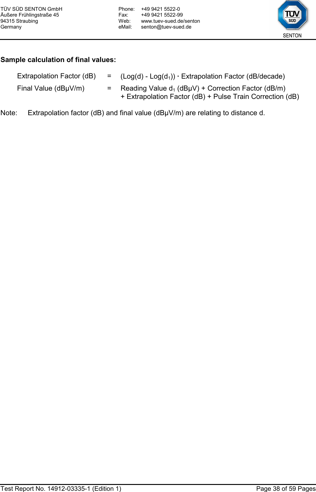
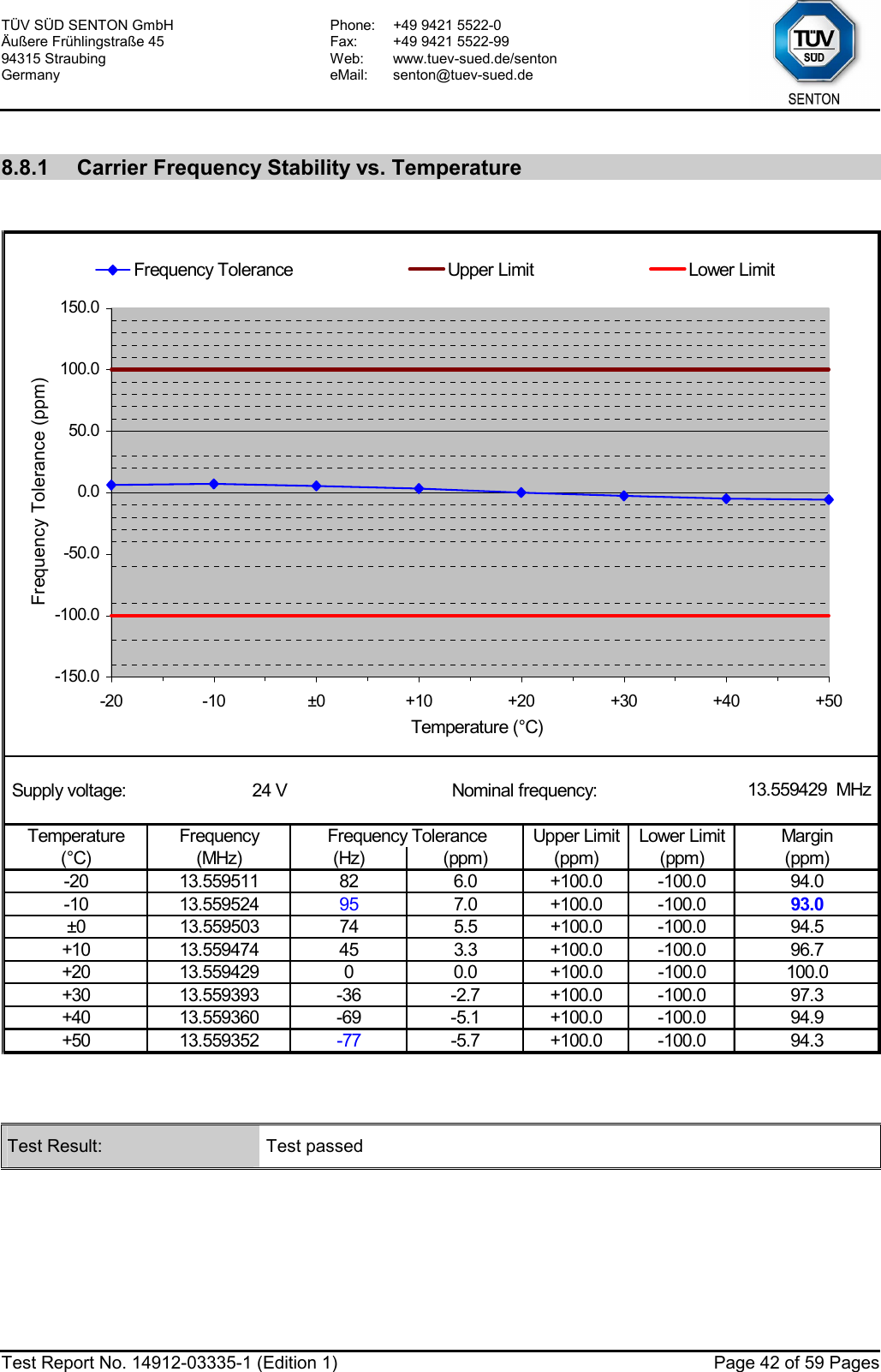
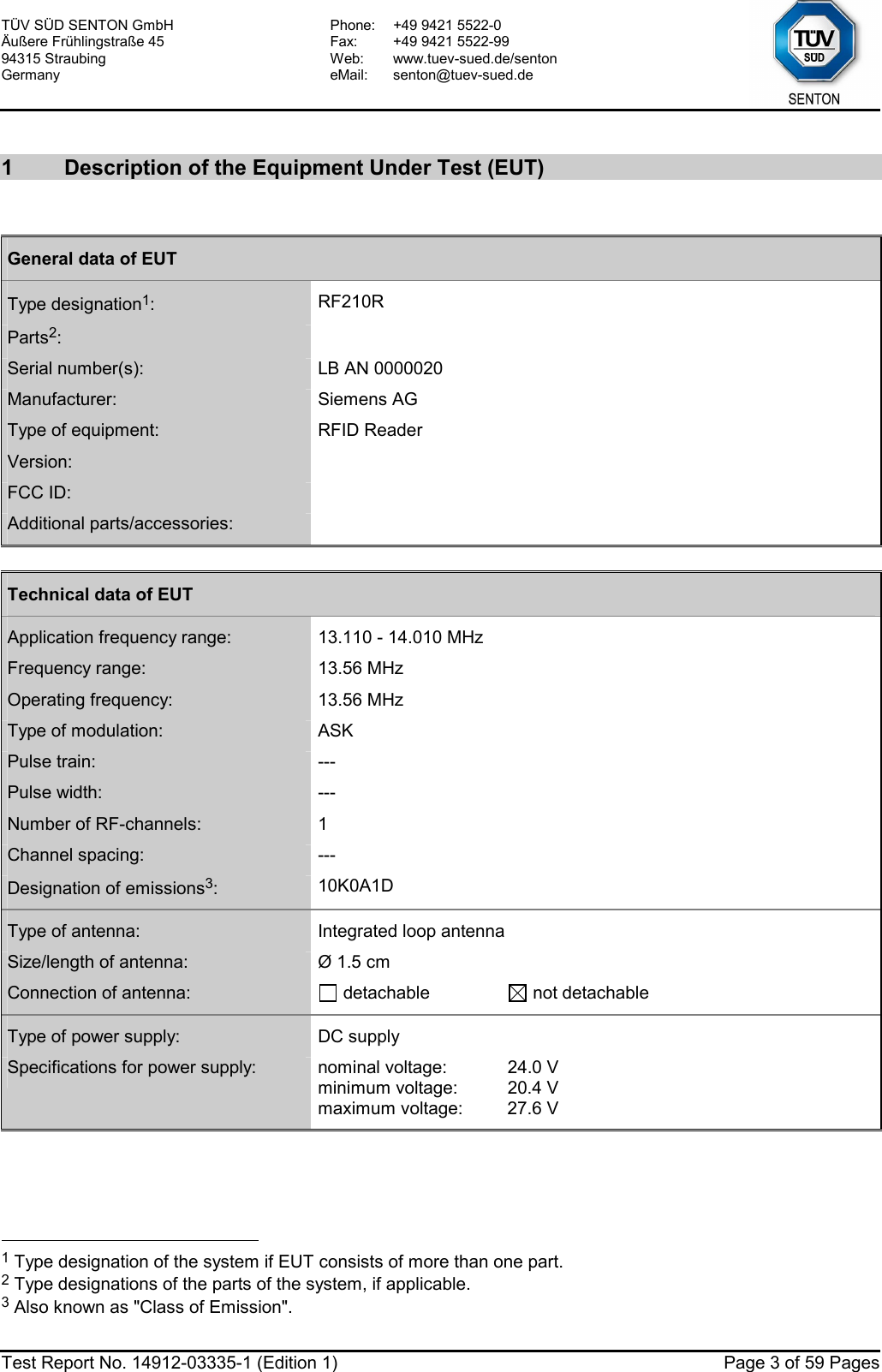
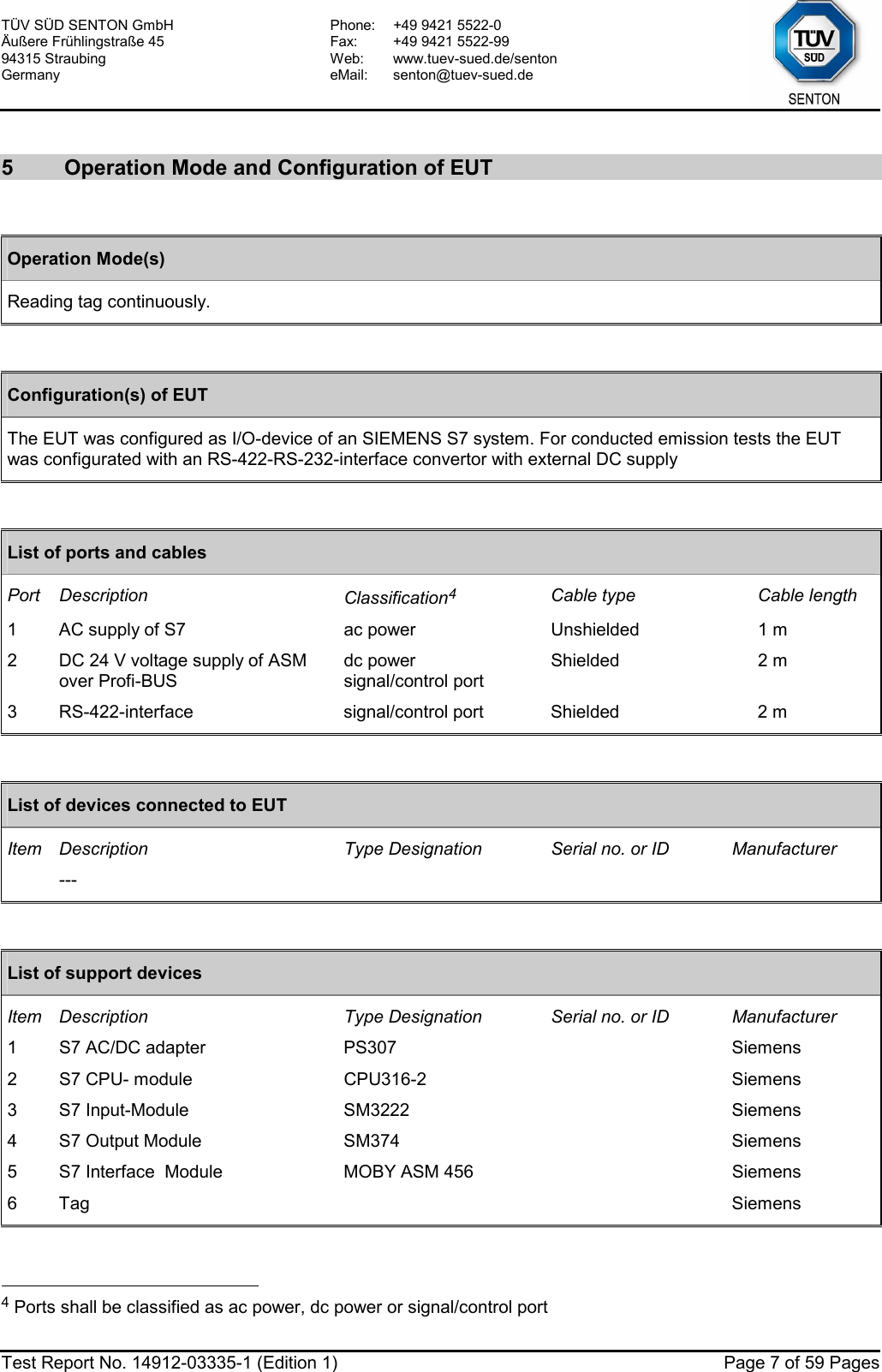
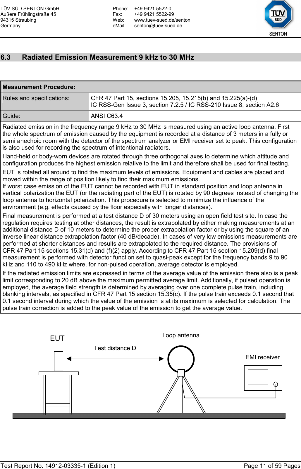
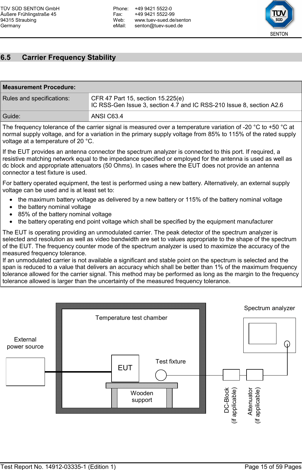
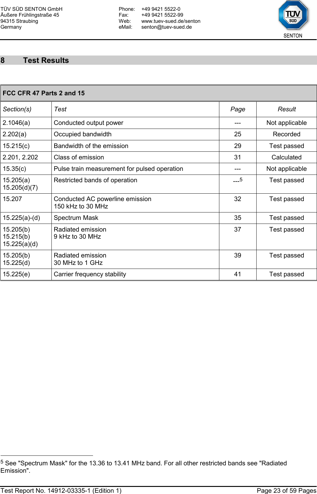
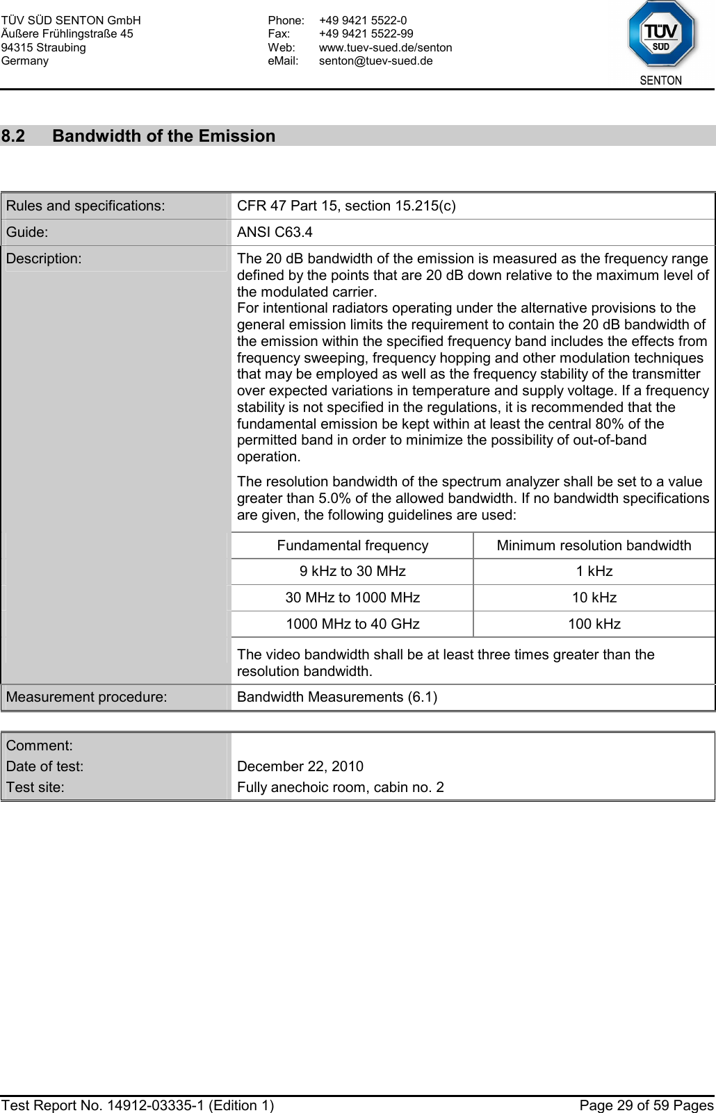
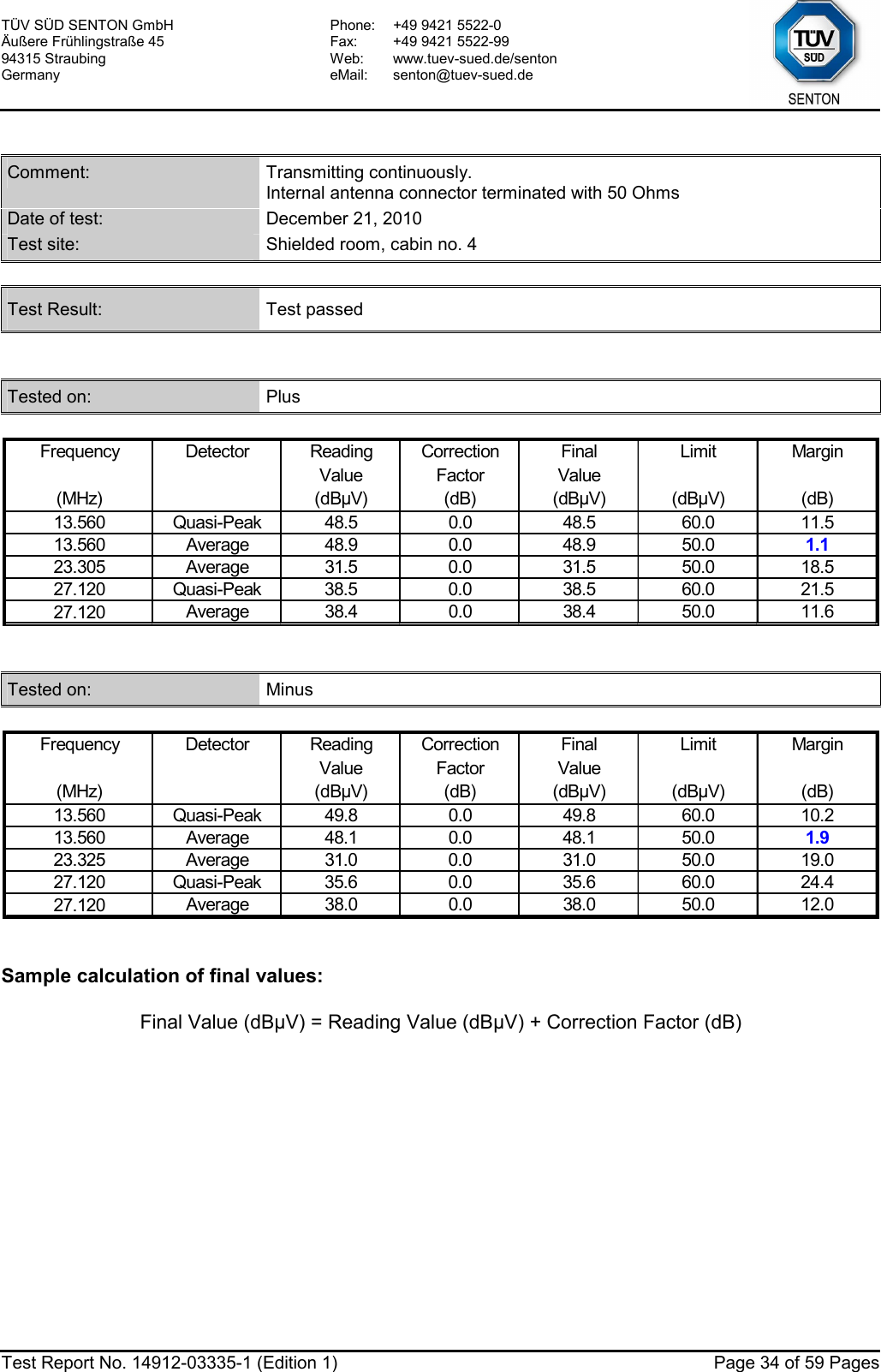
![TÜV SÜD SENTON GmbH Äußere Frühlingstraße 45 94315 Straubing Germany Phone: +49 9421 5522-0 Fax: +49 9421 5522-99 Web: www.tuev-sued.de/senton eMail: senton@tuev-sued.de Test Report No. 14912-03335-1 (Edition 1) Page 28 of 59 Pages Occupied Bandwidth (99 %): Att 0 dB** A Offset 20 dBLVLRef 70 dBµVPS 2 kHz/Center 13.55944 MHz Span 20 kHz*3DBRBW 1 kHzDCVBW 10 kHzSGLSWT 10 s**1 RMCLRWR-30-20-100102030405060701Marker 1 [T1 ] 39.23 dBµV 13.559280000 MHzOBW 14.680000000 kHzT1Temp 1 [T1 OBW] 12.68 dBµV 13.552040000 MHzT2Temp 2 [T1 OBW] 13.12 dBµV 13.566720000 MHzDate: 22.DEC.2010 13:46:20 Occupied Bandwidth (99 %): 14.68 kHz](https://usermanual.wiki/Siemens/RF210R.user-manual-II/User-Guide-1417606-Page-28.png)
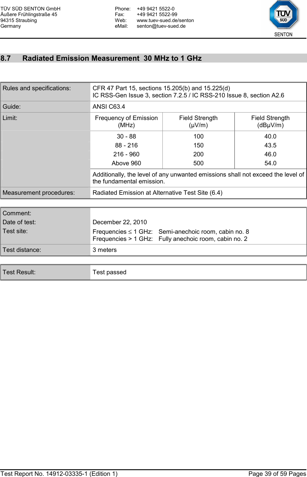
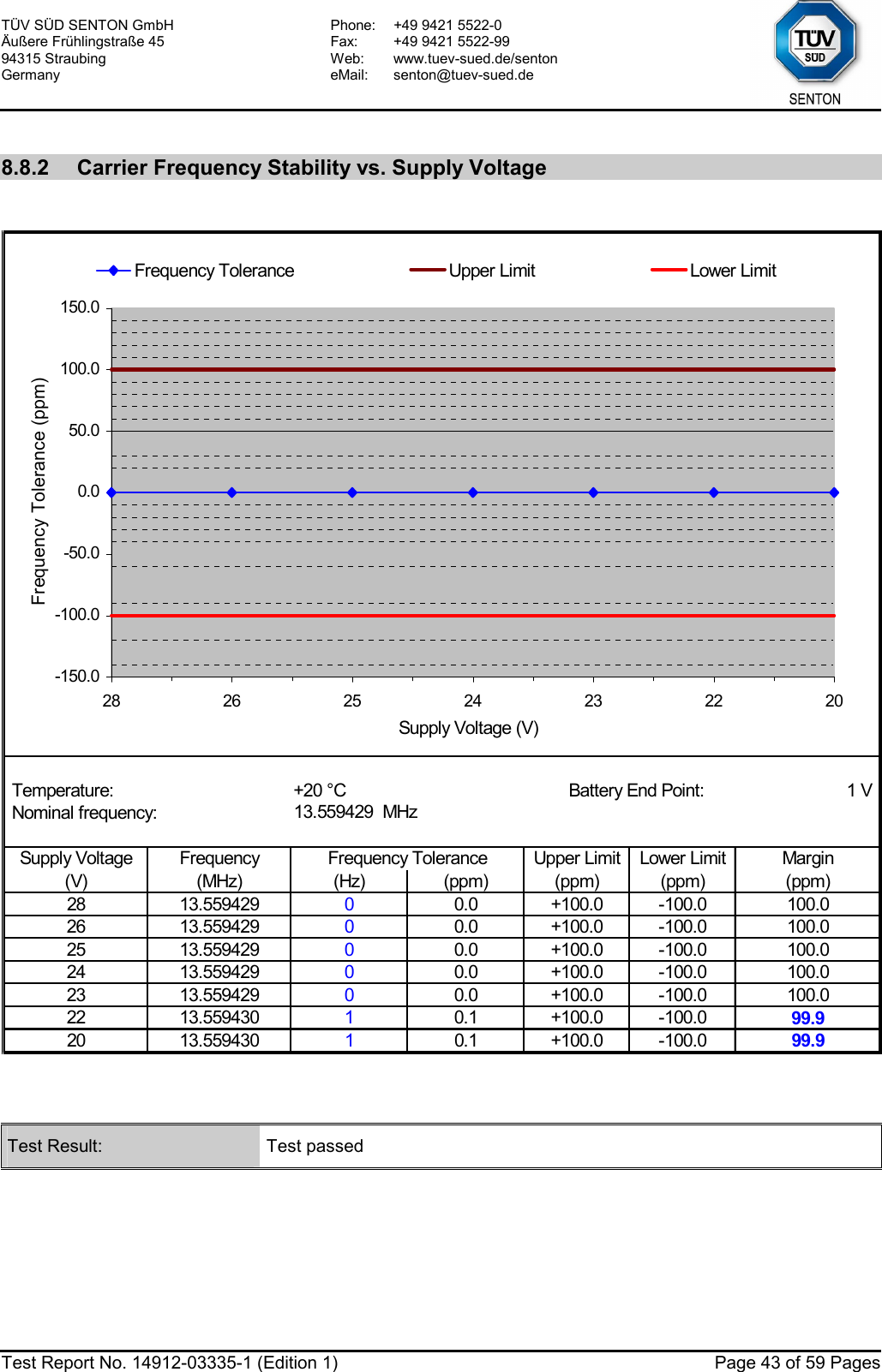
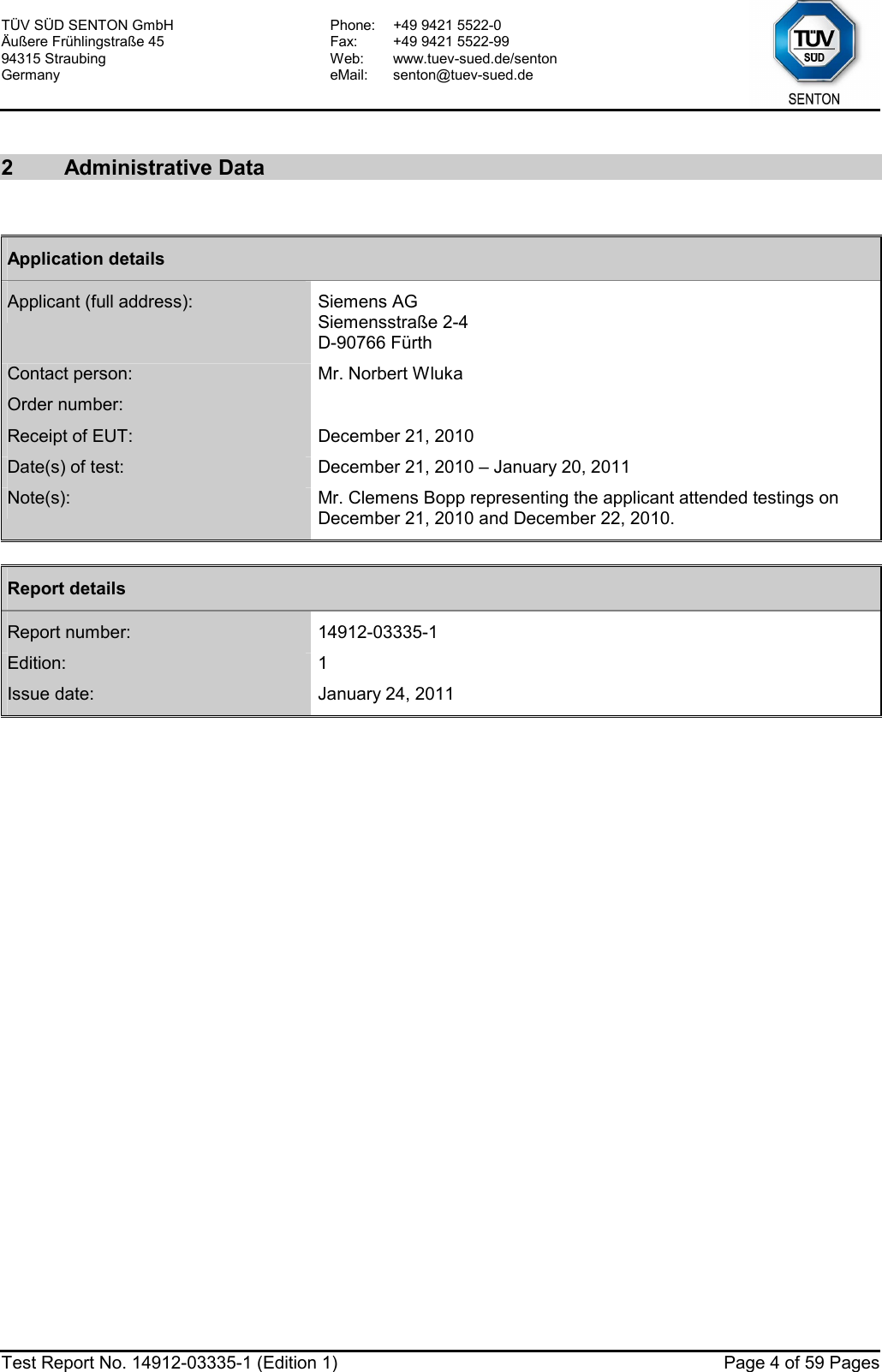
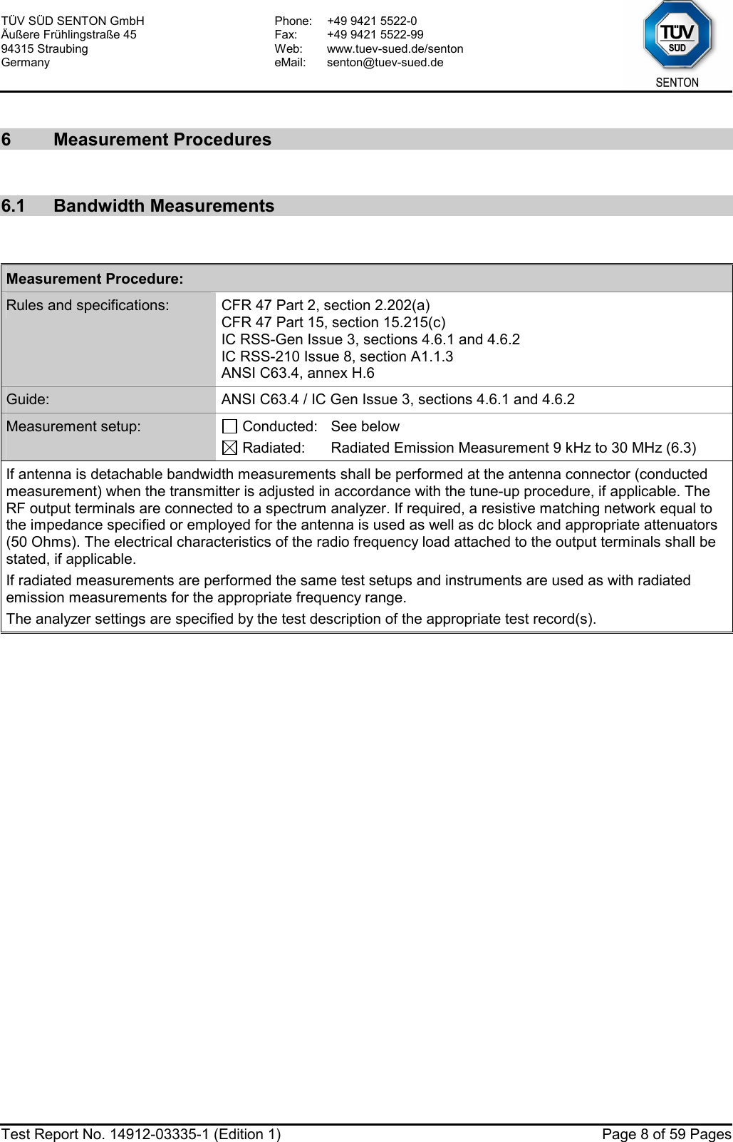
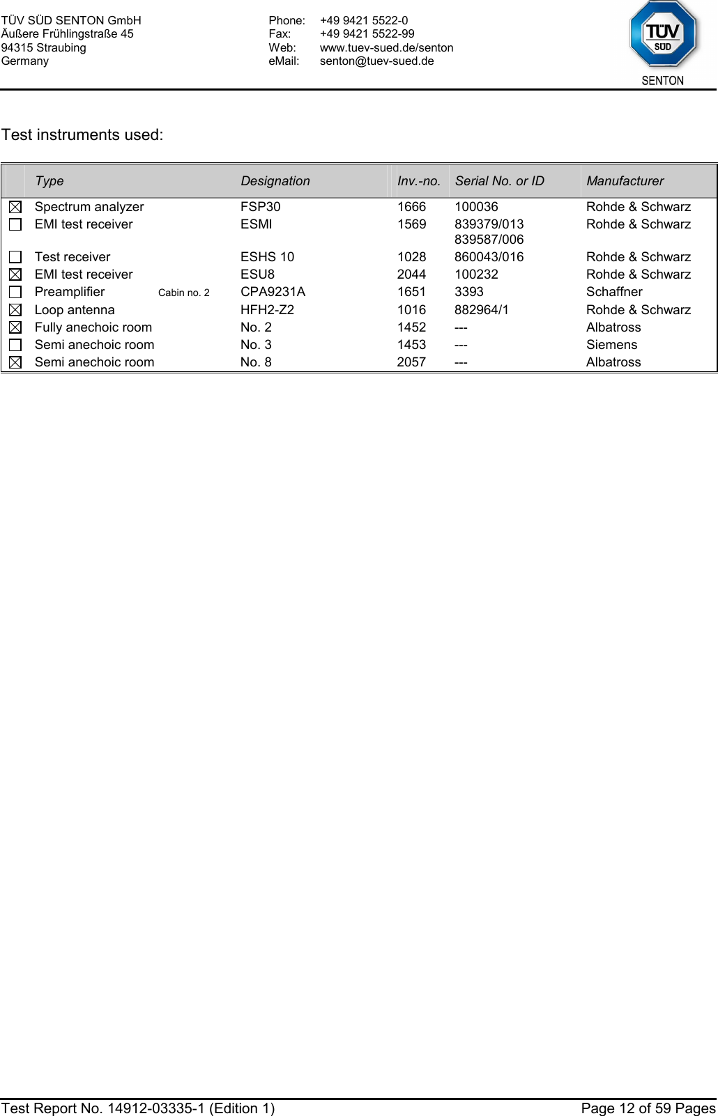
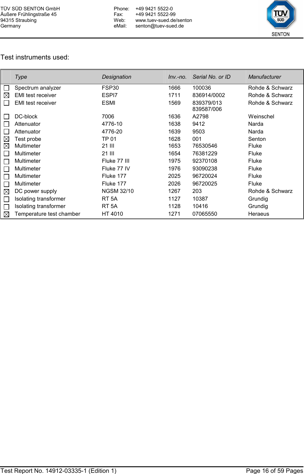
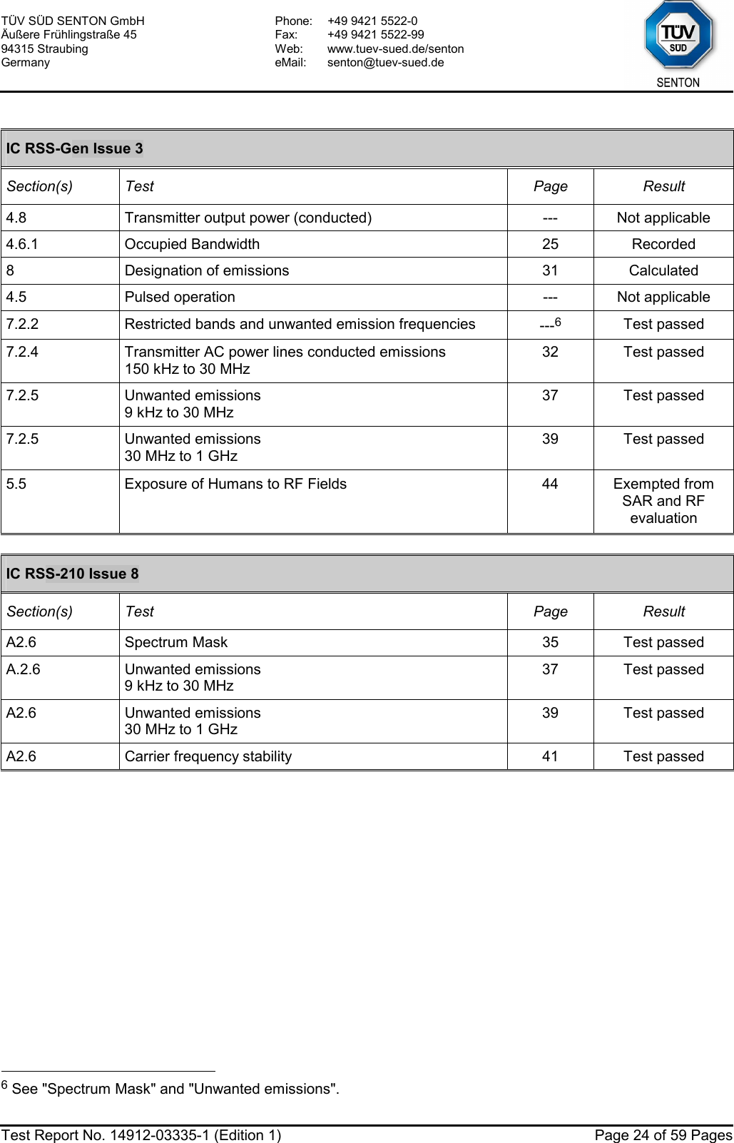
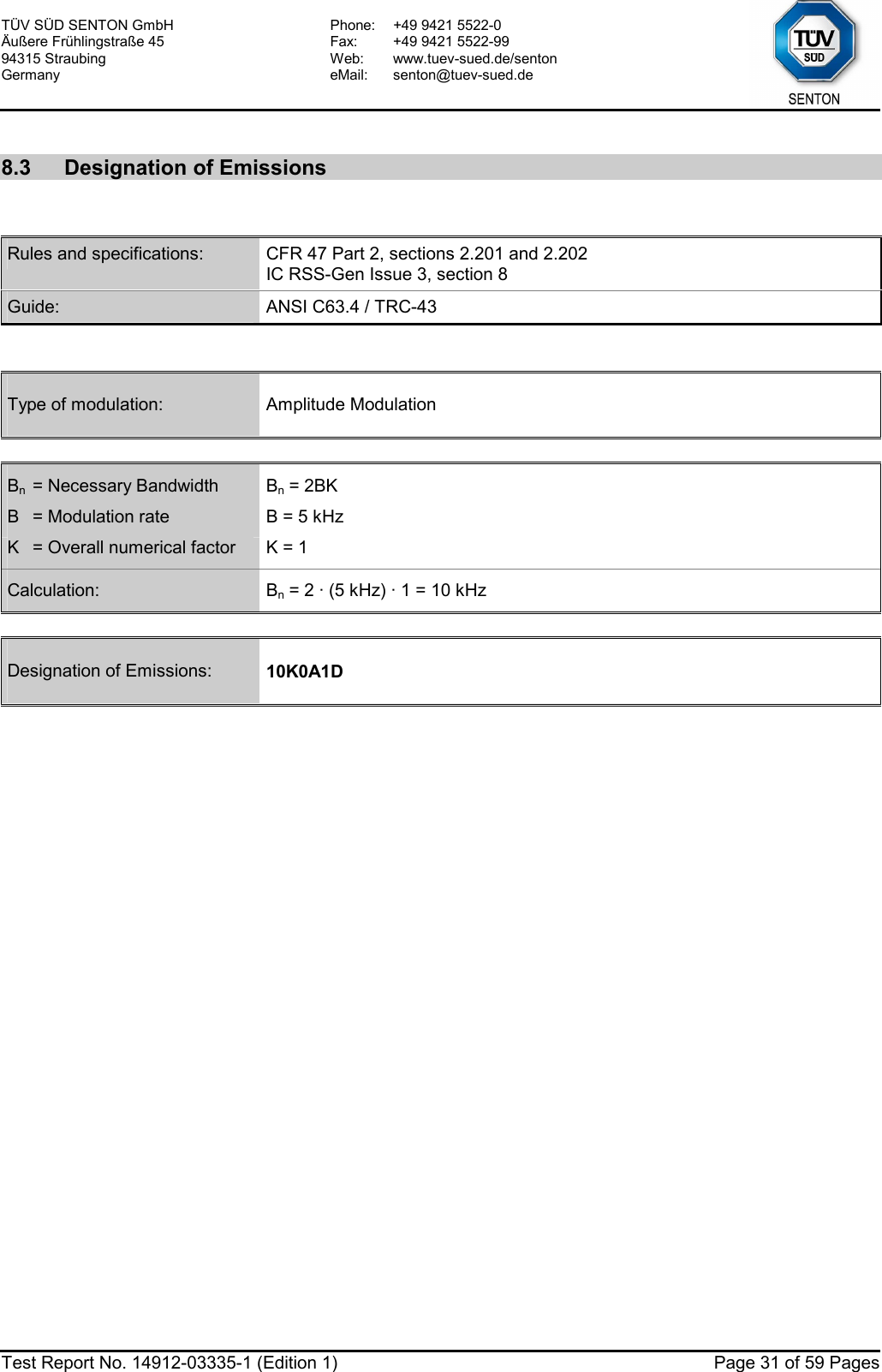
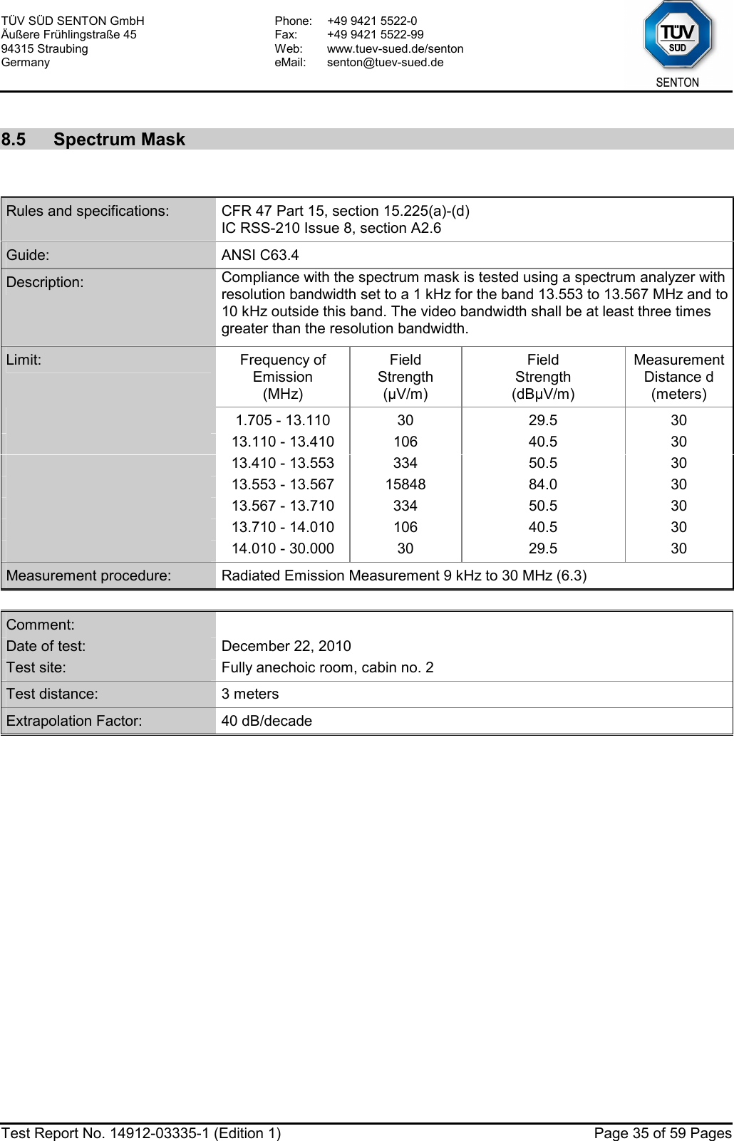
![TÜV SÜD SENTON GmbH Äußere Frühlingstraße 45 94315 Straubing Germany Phone: +49 9421 5522-0 Fax: +49 9421 5522-99 Web: www.tuev-sued.de/senton eMail: senton@tuev-sued.de Test Report No. 14912-03335-1 (Edition 1) Page 30 of 59 Pages Att 0 dB* A Offset 20 dBLVLRef 70 dBµVPS 20 kHz/Center 13.56 MHz Span 200 kHz*3DBRBW 1 kHzSWT 200 msDCVBW 3 kHz1 PKVIEW-30-20-100102030405060701Marker 1 [T1 ] 40.19 dBµV 13.559600000 MHz2Marker 2 [T1 ] 19.37 dBµV 13.556800000 MHz3Marker 3 [T1 ] 19.20 dBµV 13.562800000 MHzD1 20.11 dBµVDate: 22.DEC.2010 13:45:20 Permitted frequency band: 13.110 - 14.010 MHz 20 dB bandwidth: 6.0 kHz Carrier frequency stability: specified not specified Maximum frequency tolerances: +0.095 kHz -0.077 kHz Bandwidth of the emission: 6.2 kHz within permitted frequency band7: yes no Test Result: Test passed 7 If a frequency stability is not specified, it is recommended that the fundamental emission is kept within at least the central 80% of the permitted band in order to minimize the possibility of out-of-band operation.](https://usermanual.wiki/Siemens/RF210R.user-manual-II/User-Guide-1417606-Page-30.png)
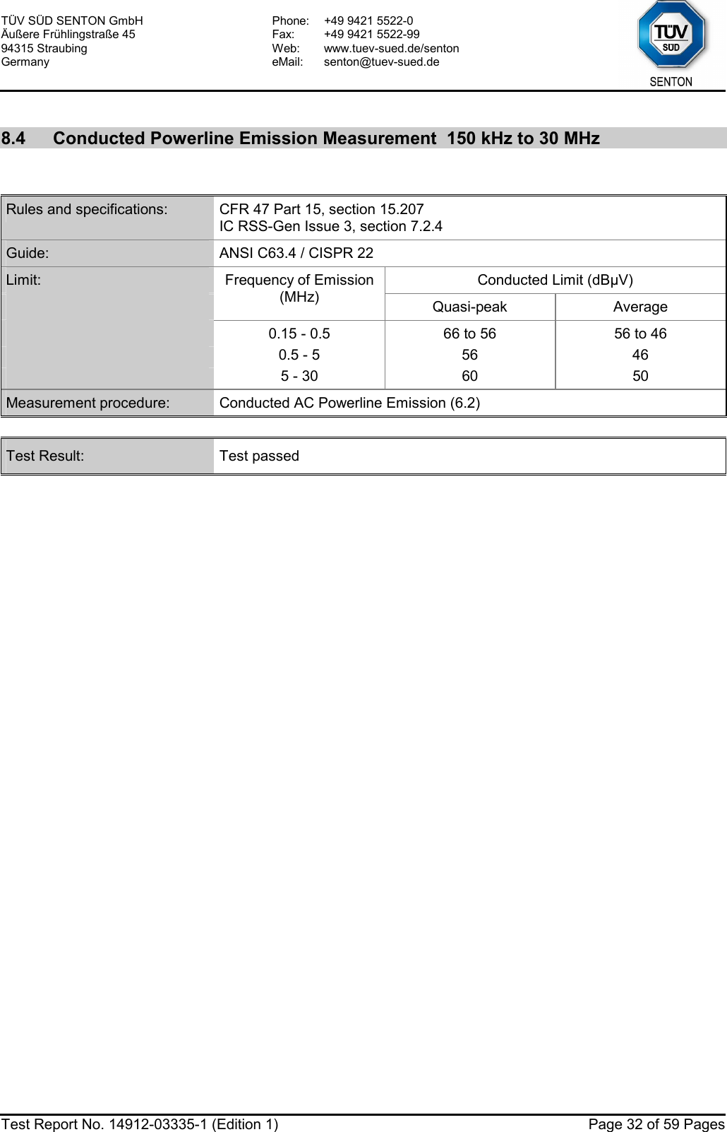
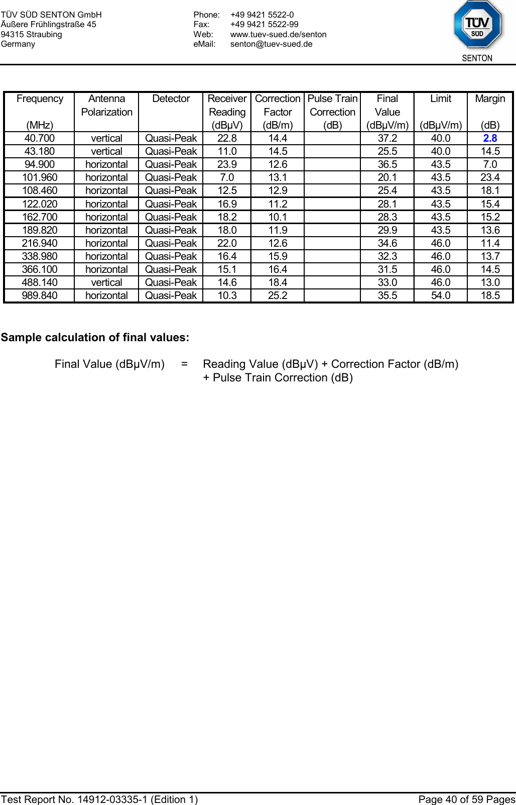
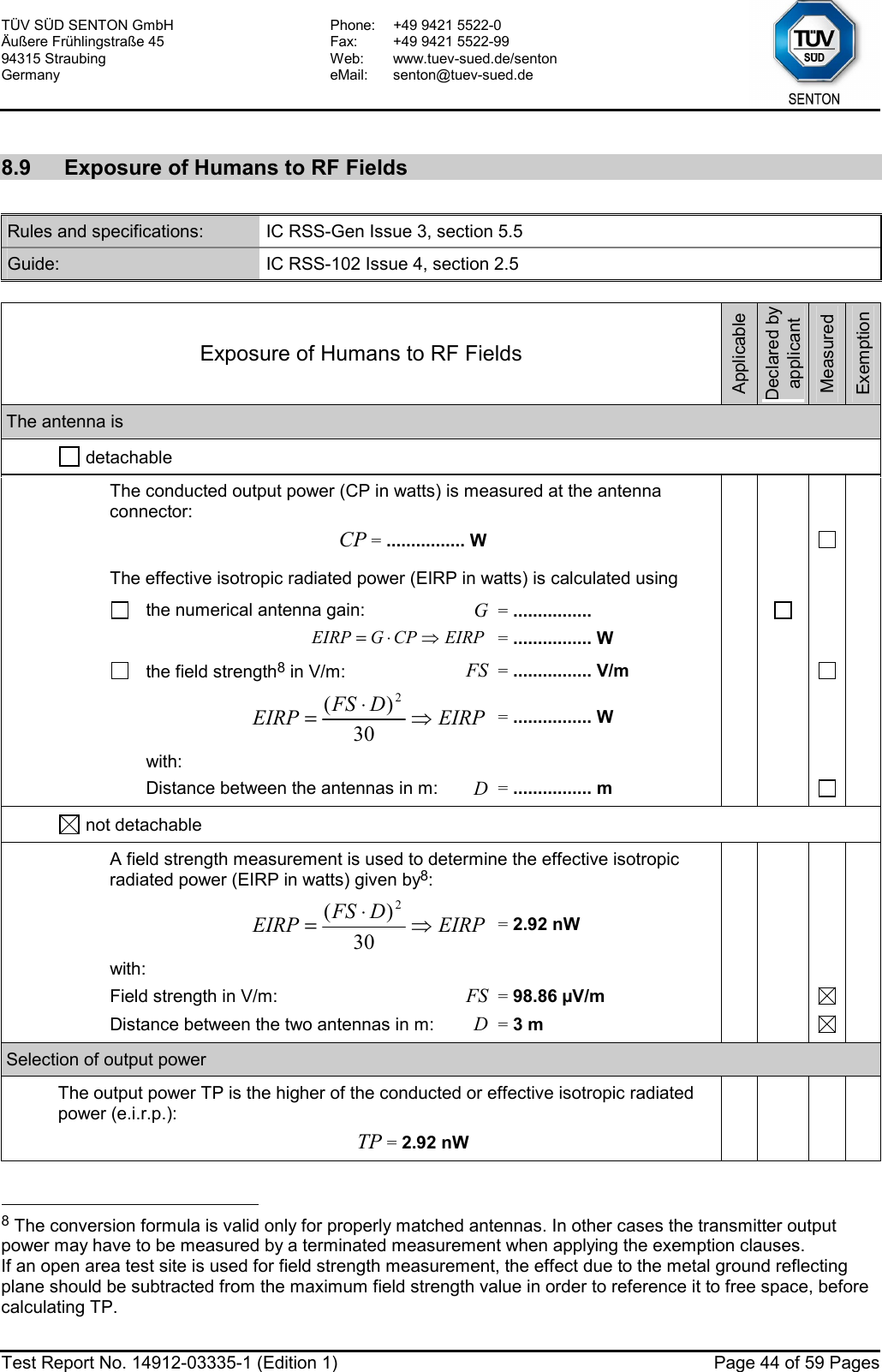
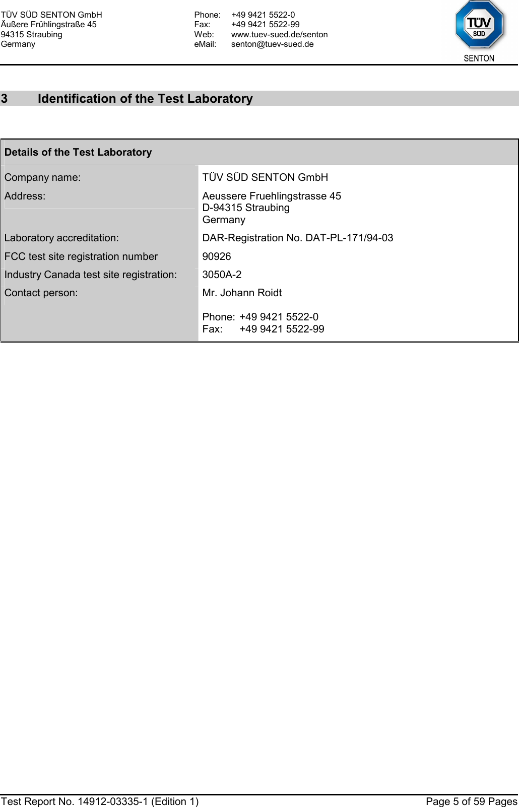
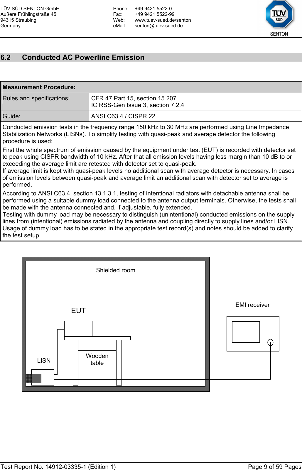
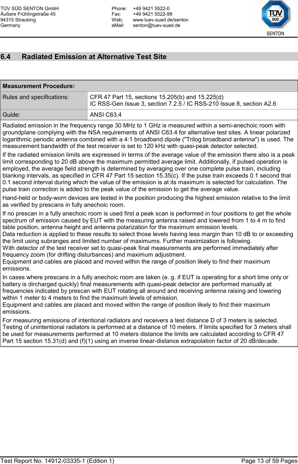
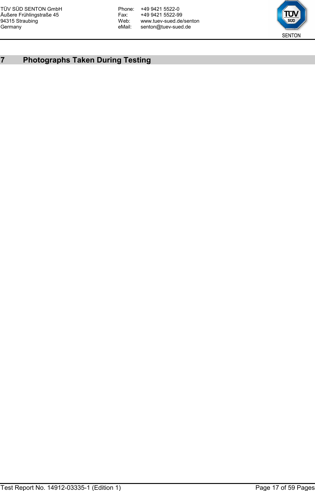
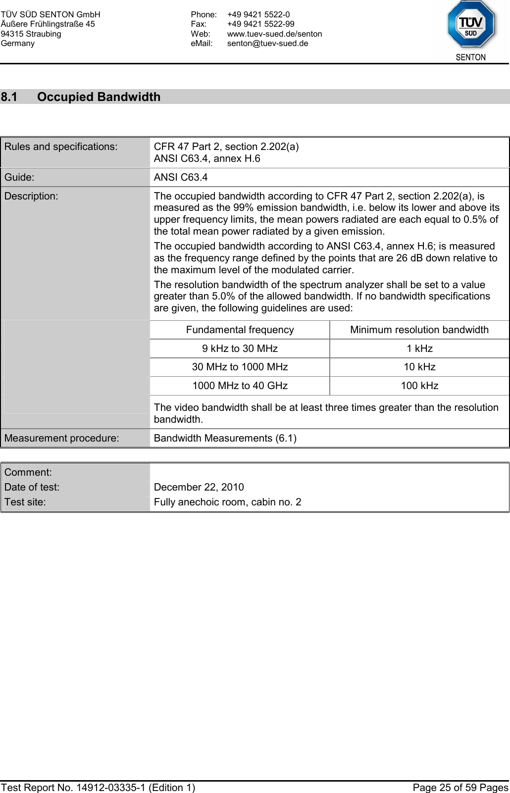
![TÜV SÜD SENTON GmbH Äußere Frühlingstraße 45 94315 Straubing Germany Phone: +49 9421 5522-0 Fax: +49 9421 5522-99 Web: www.tuev-sued.de/senton eMail: senton@tuev-sued.de Test Report No. 14912-03335-1 (Edition 1) Page 36 of 59 Pages Test Result: Test passed Att 0 dB* A PS DCRef 107 dBµVOffset 20 dBCenter 13.56 MHz Span 1 MHz100 kHz/LVL*3DBRBW 10 kHzVBW 30 kHzSWT 10 ms1 PKMAXH1020304050607080901001Marker 1 [T1 ] 41.99 dBµV 13.560000000 MHzFCC225_3Date: 22.DEC.2010 13:41:21 Att 0 dB* A PS DCRef 107 dBµVOffset 20 dBCenter 13.56 MHz Span 1 MHz100 kHz/LVL1 PKMAXH*3DBRBW 1 kHzVBW 3 kHzSWT 1 s1020304050607080901001Marker 1 [T1 ] 40.11 dBµV 13.560000000 MHzFCC225_3Date: 22.DEC.2010 13:41:56](https://usermanual.wiki/Siemens/RF210R.user-manual-II/User-Guide-1417606-Page-36.png)