Contents
- 1. user manual I
- 2. user manual II
- 3. user manual
user manual II
Note:
The test data of this report is related only to the individual item which has been tested. This report shall not
be reproduced except in full extent without the written approval of the testing laboratory.
Trade Register Straubing HRB 9302
V.A.T. DE 131457658
Information pursuant to Section 2(1)
DL-InfoV (Germany) at
www.tuev-sued.com/imprint Managing Director:
Johann Roidt
Phone: +49 9421 55 22-0
Fax: +49 9421 55 22-99
www.tuev-sued.de/senton
TÜV SÜD SENTON GmbH
Äußere Frühlingstraße 45
94315 Straubing
German
y
Prüfbericht / Test Report Nr. / No. 14912-03335-1 (Edition 1)
Applicant: Siemens AG
Type of equipment: RFID Reader
Type designation: RF210R
Order No.:
Test standards: FCC Code of Federal Regulations,
CFR 47, Part 15,
Sections 15.205, 15.207, 15.215 and 15.225
Industry Canada Radio Standards Specifications
RSS-Gen Issue 3, Section 7.2.2, 7.2.4, 7.2.5 and
RSS-210 Issue 8, Section A2.6 (Category I Equipment)
January 24, 2011
Page 1 of 59

TÜV SÜD SENTON GmbH
Äußere Frühlingstraße 45
94315 Straubing
Germany
Phone: +49 9421 5522-0
Fax: +49 9421 5522-99
Web: www.tuev-sued.de/senton
eMail: senton@tuev-sued.de
Test Report No. 14912-03335-1 (Edition 1) Page 2 of 59 Pages
Table of Contents
1 Description of the Equipment Under Test (EUT)............................................................ 3
2 Administrative Data ........................................................................................................ 4
3 Identification of the Test Laboratory............................................................................... 5
4 Summary........................................................................................................................ 6
5 Operation Mode and Configuration of EUT.................................................................... 7
6 Measurement Procedures.............................................................................................. 8
6.1 Bandwidth Measurements ....................................................................................... 8
6.2 Conducted AC Powerline Emission ......................................................................... 9
6.3 Radiated Emission Measurement 9 kHz to 30 MHz............................................... 11
6.4 Radiated Emission at Alternative Test Site............................................................ 13
6.5 Carrier Frequency Stability..................................................................................... 15
7 Photographs Taken During Testing.............................................................................. 17
8 Test Results ................................................................................................................. 23
8.1 Occupied Bandwidth.............................................................................................. 25
8.2 Bandwidth of the Emission..................................................................................... 29
8.3 Designation of Emissions....................................................................................... 31
8.4 Conducted Powerline Emission Measurement 150 kHz to 30 MHz...................... 32
8.5 Spectrum Mask...................................................................................................... 35
8.6 Radiated Emission Measurement 9 kHz to 30 MHz.............................................. 37
8.7 Radiated Emission Measurement 30 MHz to 1 GHz............................................. 39
8.8 Carrier Frequency Stability..................................................................................... 41
8.9 Exposure of Humans to RF Fields......................................................................... 44
9 Referenced Regulations............................................................................................... 46
10 Revision History ........................................................................................................... 48
11 Charts taken during testing .......................................................................................... 49
12 Calibration Data ........................................................................................................... 58

TÜV SÜD SENTON GmbH
Äußere Frühlingstraße 45
94315 Straubing
Germany
Phone: +49 9421 5522-0
Fax: +49 9421 5522-99
Web: www.tuev-sued.de/senton
eMail: senton@tuev-sued.de
Test Report No. 14912-03335-1 (Edition 1) Page 3 of 59 Pages
1 Description of the Equipment Under Test (EUT)
General data of EUT
Type designation1: RF210R
Parts2:
Serial number(s): LB AN 0000020
Manufacturer: Siemens AG
Type of equipment: RFID Reader
Version:
FCC ID:
Additional parts/accessories:
Technical data of EUT
Application frequency range: 13.110 - 14.010 MHz
Frequency range: 13.56 MHz
Operating frequency: 13.56 MHz
Type of modulation: ASK
Pulse train: ---
Pulse width: ---
Number of RF-channels: 1
Channel spacing: ---
Designation of emissions3: 10K0A1D
Type of antenna: Integrated loop antenna
Size/length of antenna: Ø 1.5 cm
Connection of antenna: detachable not detachable
Type of power supply: DC supply
Specifications for power supply: nominal voltage: 24.0 V
minimum voltage: 20.4 V
maximum voltage: 27.6 V
1 Type designation of the system if EUT consists of more than one part.
2 Type designations of the parts of the system, if applicable.
3 Also known as "Class of Emission".

TÜV SÜD SENTON GmbH
Äußere Frühlingstraße 45
94315 Straubing
Germany
Phone: +49 9421 5522-0
Fax: +49 9421 5522-99
Web: www.tuev-sued.de/senton
eMail: senton@tuev-sued.de
Test Report No. 14912-03335-1 (Edition 1) Page 4 of 59 Pages
2 Administrative Data
Application details
Applicant (full address): Siemens AG
Siemensstraße 2-4
D-90766 Fürth
Contact person: Mr. Norbert Wluka
Order number:
Receipt of EUT: December 21, 2010
Date(s) of test: December 21, 2010 – January 20, 2011
Note(s): Mr. Clemens Bopp representing the applicant attended testings on
December 21, 2010 and December 22, 2010.
Report details
Report number: 14912-03335-1
Edition: 1
Issue date: January 24, 2011

TÜV SÜD SENTON GmbH
Äußere Frühlingstraße 45
94315 Straubing
Germany
Phone: +49 9421 5522-0
Fax: +49 9421 5522-99
Web: www.tuev-sued.de/senton
eMail: senton@tuev-sued.de
Test Report No. 14912-03335-1 (Edition 1) Page 5 of 59 Pages
3 Identification of the Test Laboratory
Details of the Test Laboratory
Company name: TÜV SÜD SENTON GmbH
Address: Aeussere Fruehlingstrasse 45
D-94315 Straubing
Germany
Laboratory accreditation: DAR-Registration No. DAT-PL-171/94-03
FCC test site registration number 90926
Industry Canada test site registration: 3050A-2
Contact person: Mr. Johann Roidt
Phone: +49 9421 5522-0
Fax: +49 9421 5522-99
TÜV SÜD SENTON GmbH
Äußere Frühlingstraße 45
94315 Straubing
Germany
Phone: +49 9421 5522-0
Fax: +49 9421 5522-99
Web: www.tuev-sued.de/senton
eMail: senton@tuev-sued.de
Test Report No. 14912-03335-1 (Edition 1) Page 6 of 59 Pages
4 Summary
Summary of test results
The tested sample complies with the requirements set forth in the
Code of Federal Regulations CFR 47, Part 15, Sections 15.205, 15.207, 15.215 and 15.225
of the Federal Communication Commission (FCC) and the
Radio Standards Specifications
RSS-Gen Issue 3, Section 7.2.2, 7.2.4, 7.2.5 and
RSS-210 Issue 8, Section A2.6 (Category I Equipment)
of Industry Canada (IC).
Personnel involved in this report
Laboratory Manager:
Mr. Johann Roidt
Responsible for testing:
Mr. Martin Steindl
Responsible for test report: Mr. Martin Steindl

TÜV SÜD SENTON GmbH
Äußere Frühlingstraße 45
94315 Straubing
Germany
Phone: +49 9421 5522-0
Fax: +49 9421 5522-99
Web: www.tuev-sued.de/senton
eMail: senton@tuev-sued.de
Test Report No. 14912-03335-1 (Edition 1) Page 7 of 59 Pages
5 Operation Mode and Configuration of EUT
Operation Mode(s)
Reading tag continuously.
Configuration(s) of EUT
The EUT was configured as I/O-device of an SIEMENS S7 system. For conducted emission tests the EUT
was configurated with an RS-422-RS-232-interface convertor with external DC supply
List of ports and cables
Port Description Classification4 Cable type Cable length
1 AC supply of S7 ac power Unshielded 1 m
2 DC 24 V voltage supply of ASM
over Profi-BUS
dc power
signal/control port
Shielded 2 m
3 RS-422-interface signal/control port Shielded 2 m
List of devices connected to EUT
Item Description Type Designation Serial no. or ID Manufacturer
---
List of support devices
Item Description Type Designation Serial no. or ID Manufacturer
1 S7 AC/DC adapter PS307 Siemens
2 S7 CPU- module CPU316-2 Siemens
3 S7 Input-Module SM3222 Siemens
4 S7 Output Module SM374 Siemens
5 S7 Interface Module MOBY ASM 456 Siemens
6 Tag Siemens
4 Ports shall be classified as ac power, dc power or signal/control port
TÜV SÜD SENTON GmbH
Äußere Frühlingstraße 45
94315 Straubing
Germany
Phone: +49 9421 5522-0
Fax: +49 9421 5522-99
Web: www.tuev-sued.de/senton
eMail: senton@tuev-sued.de
Test Report No. 14912-03335-1 (Edition 1) Page 8 of 59 Pages
6 Measurement Procedures
6.1 Bandwidth Measurements
Measurement Procedure:
Rules and specifications: CFR 47 Part 2, section 2.202(a)
CFR 47 Part 15, section 15.215(c)
IC RSS-Gen Issue 3, sections 4.6.1 and 4.6.2
IC RSS-210 Issue 8, section A1.1.3
ANSI C63.4, annex H.6
Guide: ANSI C63.4 / IC Gen Issue 3, sections 4.6.1 and 4.6.2
Measurement setup: Conducted: See below
Radiated: Radiated Emission Measurement 9 kHz to 30 MHz (6.3)
If antenna is detachable bandwidth measurements shall be performed at the antenna connector (conducted
measurement) when the transmitter is adjusted in accordance with the tune-up procedure, if applicable. The
RF output terminals are connected to a spectrum analyzer. If required, a resistive matching network equal to
the impedance specified or employed for the antenna is used as well as dc block and appropriate attenuators
(50 Ohms). The electrical characteristics of the radio frequency load attached to the output terminals shall be
stated, if applicable.
If radiated measurements are performed the same test setups and instruments are used as with radiated
emission measurements for the appropriate frequency range.
The analyzer settings are specified by the test description of the appropriate test record(s).
TÜV SÜD SENTON GmbH
Äußere Frühlingstraße 45
94315 Straubing
Germany
Phone: +49 9421 5522-0
Fax: +49 9421 5522-99
Web: www.tuev-sued.de/senton
eMail: senton@tuev-sued.de
Test Report No. 14912-03335-1 (Edition 1) Page 9 of 59 Pages
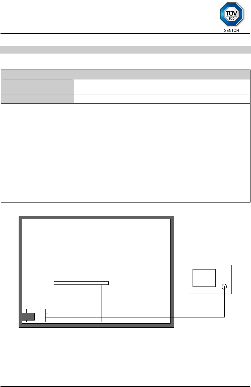
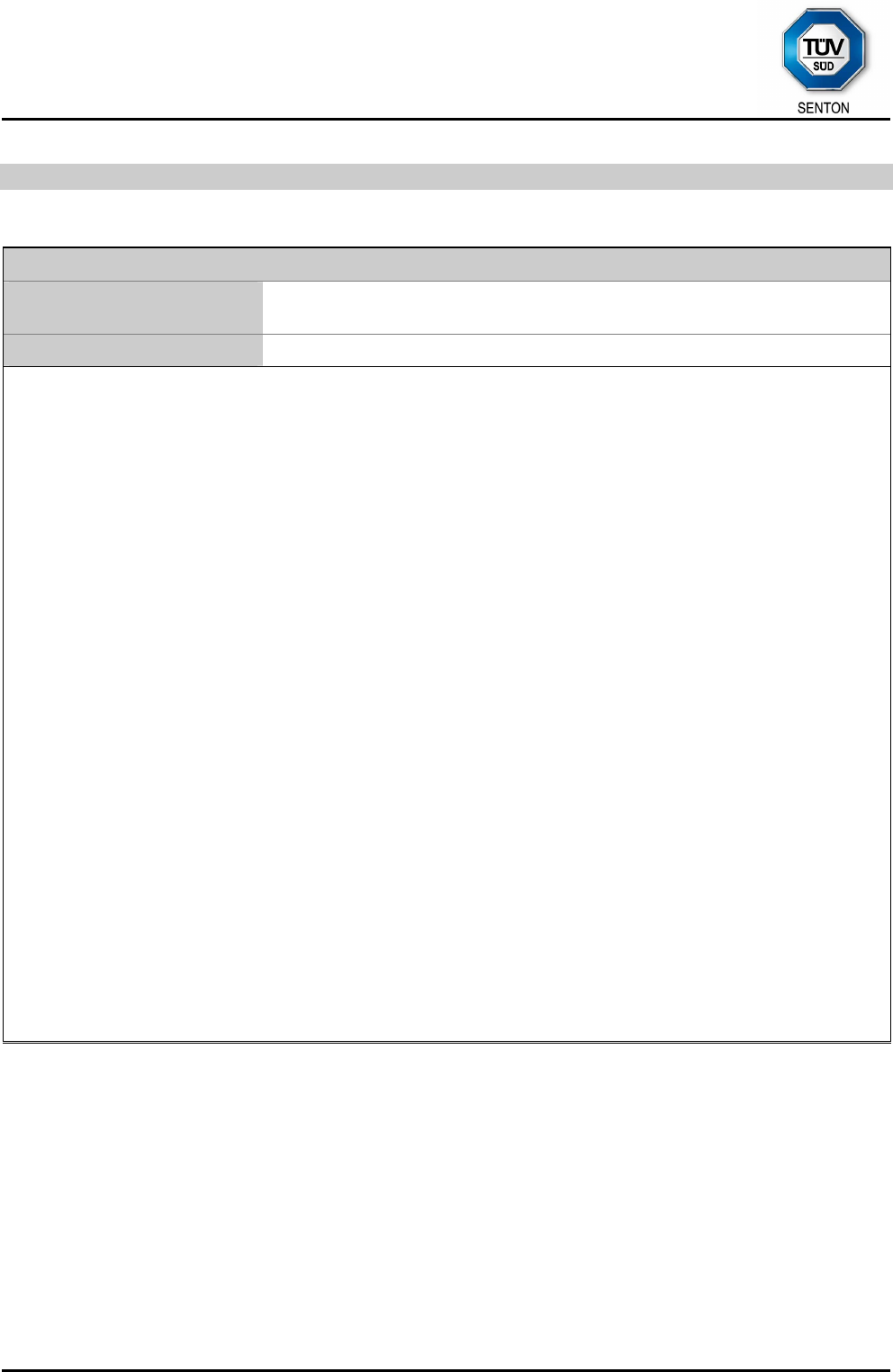
6.2 Conducted AC Powerline Emission
Measurement Procedure:
Rules and specifications: CFR 47 Part 15, section 15.207
IC RSS-Gen Issue 3, section 7.2.4
Guide: ANSI C63.4 / CISPR 22
Conducted emission tests in the frequency range 150 kHz to 30 MHz are performed using Line Impedance
Stabilization Networks (LISNs). To simplify testing with quasi-peak and average detector the following
procedure is used:
First the whole spectrum of emission caused by the equipment under test (EUT) is recorded with detector set
to peak using CISPR bandwidth of 10 kHz. After that all emission levels having less margin than 10 dB to or
exceeding the average limit are retested with detector set to quasi-peak.
If average limit is kept with quasi-peak levels no additional scan with average detector is necessary. In cases
of emission levels between quasi-peak and average limit an additional scan with detector set to average is
performed.
According to ANSI C63.4, section 13.1.3.1, testing of intentional radiators with detachable antenna shall be
performed using a suitable dummy load connected to the antenna output terminals. Otherwise, the tests shall
be made with the antenna connected and, if adjustable, fully extended.
Testing with dummy load may be necessary to distinguish (unintentional) conducted emissions on the supply
lines from (intentional) emissions radiated by the antenna and coupling directly to supply lines and/or LISN.
Usage of dummy load has to be stated in the appropriate test record(s) and notes should be added to clarify
the test setup.
LISN
EUT EMI receiver
LISN
EUT
Shielded room
LISN
EUT
Wooden
table

TÜV SÜD SENTON GmbH
Äußere Frühlingstraße 45
94315 Straubing
Germany
Phone: +49 9421 5522-0
Fax: +49 9421 5522-99
Web: www.tuev-sued.de/senton
eMail: senton@tuev-sued.de
Test Report No. 14912-03335-1 (Edition 1) Page 10 of 59 Pages
Test instruments used:
Type Designation Inv.-no. Serial No. or ID Manufacturer
Test receiver ESHS 10 1028 860043/016 Rohde & Schwarz
V-network ESH 3-Z5 1059 894785/005 Rohde & Schwarz
V-network ESH 3-Z5 1218 830952/025 Rohde & Schwarz
Artificial mains network ESH 2-Z5 1536 842966/004 Rohde & Schwarz
Shielded room No. 1 1451 --- Albatross
Shielded room No. 4 1454 3FD 100 544 Euroshield
TÜV SÜD SENTON GmbH
Äußere Frühlingstraße 45
94315 Straubing
Germany
Phone: +49 9421 5522-0
Fax: +49 9421 5522-99
Web: www.tuev-sued.de/senton
eMail: senton@tuev-sued.de
Test Report No. 14912-03335-1 (Edition 1) Page 11 of 59 Pages
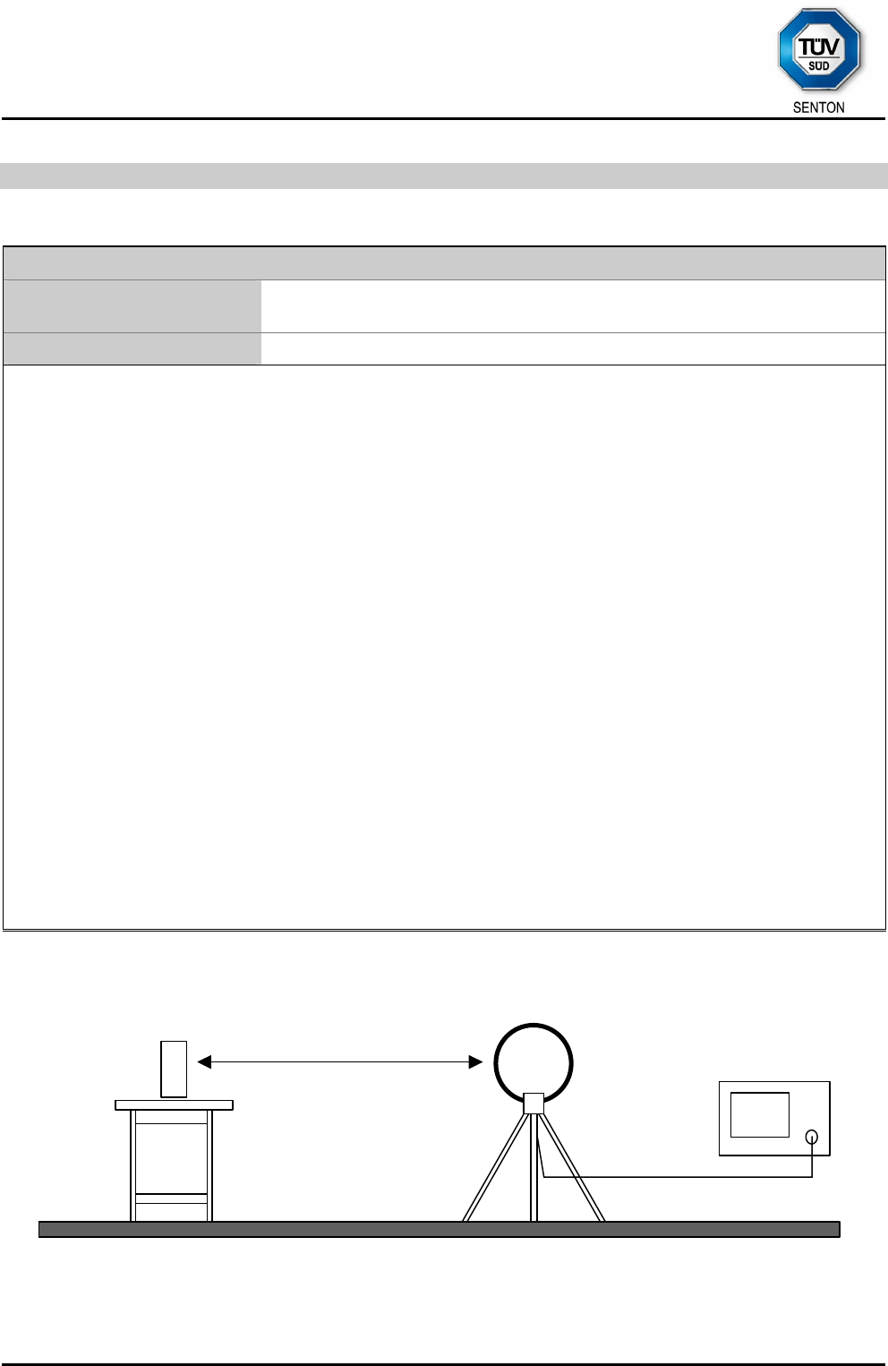
6.3 Radiated Emission Measurement 9 kHz to 30 MHz
Measurement Procedure:
Rules and specifications: CFR 47 Part 15, sections 15.205, 15.215(b) and 15.225(a)-(d)
IC RSS-Gen Issue 3, section 7.2.5 / IC RSS-210 Issue 8, section A2.6
Guide: ANSI C63.4
Radiated emission in the frequency range 9 kHz to 30 MHz is measured using an active loop antenna. First
the whole spectrum of emission caused by the equipment is recorded at a distance of 3 meters in a fully or
semi anechoic room with the detector of the spectrum analyzer or EMI receiver set to peak. This configuration
is also used for recording the spectrum of intentional radiators.
Hand-held or body-worn devices are rotated through three orthogonal axes to determine which attitude and
configuration produces the highest emission relative to the limit and therefore shall be used for final testing.
EUT is rotated all around to find the maximum levels of emissions. Equipment and cables are placed and
moved within the range of position likely to find their maximum emissions.
If worst case emission of the EUT cannot be recorded with EUT in standard position and loop antenna in
vertical polarization the EUT (or the radiating part of the EUT) is rotated by 90 degrees instead of changing the
loop antenna to horizontal polarization. This procedure is selected to minimize the influence of the
environment (e.g. effects caused by the floor especially with longer distances).
Final measurement is performed at a test distance D of 30 meters using an open field test site. In case the
regulation requires testing at other distances, the result is extrapolated by either making measurements at an
additional distance D of 10 meters to determine the proper extrapolation factor or by using the square of an
inverse linear distance extrapolation factor (40 dB/decade). In cases of very low emissions measurements are
performed at shorter distances and results are extrapolated to the required distance. The provisions of
CFR 47 Part 15 sections 15.31(d) and (f)(2) apply. According to CFR 47 Part 15 section 15.209(d) final
measurement is performed with detector function set to quasi-peak except for the frequency bands 9 to 90
kHz and 110 to 490 kHz where, for non-pulsed operation, average detector is employed.
If the radiated emission limits are expressed in terms of the average value of the emission there also is a peak
limit corresponding to 20 dB above the maximum permitted average limit. Additionally, if pulsed operation is
employed, the average field strength is determined by averaging over one complete pulse train, including
blanking intervals, as specified in CFR 47 Part 15 section 15.35(c). If the pulse train exceeds 0.1 second that
0.1 second interval during which the value of the emission is at its maximum is selected for calculation. The
pulse train correction is added to the peak value of the emission to get the average value.
EUT
Test distance D
EMI receiver
Loop antenna

TÜV SÜD SENTON GmbH
Äußere Frühlingstraße 45
94315 Straubing
Germany
Phone: +49 9421 5522-0
Fax: +49 9421 5522-99
Web: www.tuev-sued.de/senton
eMail: senton@tuev-sued.de
Test Report No. 14912-03335-1 (Edition 1) Page 12 of 59 Pages
Test instruments used:
Type Designation Inv.-no. Serial No. or ID Manufacturer
Spectrum analyzer FSP30 1666 100036 Rohde & Schwarz
EMI test receiver ESMI 1569 839379/013
839587/006
Rohde & Schwarz
Test receiver ESHS 10 1028 860043/016 Rohde & Schwarz
EMI test receiver ESU8 2044 100232 Rohde & Schwarz
Preamplifier Cabin no. 2 CPA9231A 1651 3393 Schaffner
Loop antenna HFH2-Z2 1016 882964/1 Rohde & Schwarz
Fully anechoic room No. 2 1452 --- Albatross
Semi anechoic room No. 3 1453 --- Siemens
Semi anechoic room No. 8 2057 --- Albatross
TÜV SÜD SENTON GmbH
Äußere Frühlingstraße 45
94315 Straubing
Germany
Phone: +49 9421 5522-0
Fax: +49 9421 5522-99
Web: www.tuev-sued.de/senton
eMail: senton@tuev-sued.de
Test Report No. 14912-03335-1 (Edition 1) Page 13 of 59 Pages
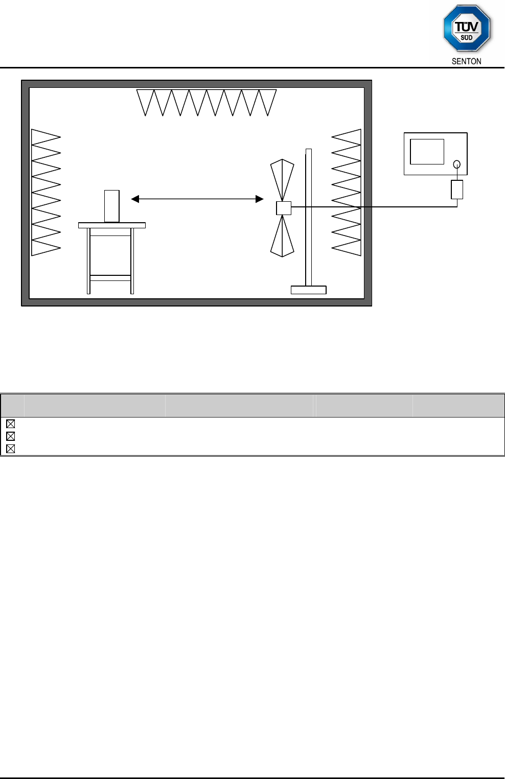
6.4 Radiated Emission at Alternative Test Site
Measurement Procedure:
Rules and specifications: CFR 47 Part 15, sections 15.205(b) and 15.225(d)
IC RSS-Gen Issue 3, section 7.2.5 / IC RSS-210 Issue 8, section A2.6
Guide: ANSI C63.4
Radiated emission in the frequency range 30 MHz to 1 GHz is measured within a semi-anechoic room with
groundplane complying with the NSA requirements of ANSI C63.4 for alternative test sites. A linear polarized
logarithmic periodic antenna combined with a 4:1 broadband dipole ("Trilog broadband antenna") is used. The
measurement bandwidth of the test receiver is set to 120 kHz with quasi-peak detector selected.
If the radiated emission limits are expressed in terms of the average value of the emission there also is a peak
limit corresponding to 20 dB above the maximum permitted average limit. Additionally, if pulsed operation is
employed, the average field strength is determined by averaging over one complete pulse train, including
blanking intervals, as specified in CFR 47 Part 15 section 15.35(c). If the pulse train exceeds 0.1 second that
0.1 second interval during which the value of the emission is at its maximum is selected for calculation. The
pulse train correction is added to the peak value of the emission to get the average value.
Hand-held or body-worn devices are tested in the position producing the highest emission relative to the limit
as verified by prescans in fully anechoic room.
If no prescan in a fully anechoic room is used first a peak scan is performed in four positions to get the whole
spectrum of emission caused by EUT with the measuring antenna raised and lowered from 1 to 4 m to find
table position, antenna height and antenna polarization for the maximum emission levels.
Data reduction is applied to these results to select those levels having less margin than 10 dB to or exceeding
the limit using subranges and limited number of maximums. Further maximization is following.
With detector of the test receiver set to quasi-peak final measurements are performed immediately after
frequency zoom (for drifting disturbances) and maximum adjustment.
Equipment and cables are placed and moved within the range of position likely to find their maximum
emissions.
In cases where prescans in a fully anechoic room are taken (e. g. if EUT is operating for a short time only or
battery is dircharged quickly) final measurements with quasi-peak detector are performed manually at
frequencies indicated by prescan with EUT rotating all around and receiving antenna raising and lowering
within 1 meter to 4 meters to find the maximum levels of emission.
Equipment and cables are placed and moved within the range of position likely to find their maximum
emissions.
For measuring emissions of intentional radiators and receivers a test distance D of 3 meters is selected.
Testing of unintentional radiators is performed at a distance of 10 meters. If limits specified for 3 meters shall
be used for measurements performed at 10 meters distance the limits are calculated according to CFR 47
Part 15 section 15.31(d) and (f)(1) using an inverse linear-distance extrapolation factor of 20 dB/decade.
TÜV SÜD SENTON GmbH
Äußere Frühlingstraße 45
94315 Straubing
Germany
Phone: +49 9421 5522-0
Fax: +49 9421 5522-99
Web: www.tuev-sued.de/senton
eMail: senton@tuev-sued.de
Test Report No. 14912-03335-1 (Edition 1) Page 14 of 59 Pages
EUT
Alternate test site (semi anechoic room)
Test distance D
EMI test receiver
Preamplifier
(if applicable)
Wooden
Table
Test
antenna
Test instruments used:
Type Designation Inv.-no. Serial No. or ID Manufacturer
EMI test receiver ESU8 2044 100232 Rohde & Schwarz
Trilog antenna Cabin no. 8 VULB 9163 1802 9163-214 Schwarzbeck
Semi anechoic room No. 8 2057 --- Albatross
TÜV SÜD SENTON GmbH
Äußere Frühlingstraße 45
94315 Straubing
Germany
Phone: +49 9421 5522-0
Fax: +49 9421 5522-99
Web: www.tuev-sued.de/senton
eMail: senton@tuev-sued.de
Test Report No. 14912-03335-1 (Edition 1) Page 15 of 59 Pages
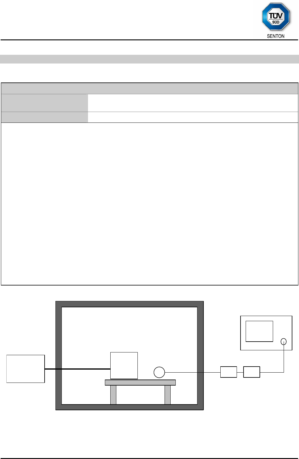
6.5 Carrier Frequency Stability
Measurement Procedure:
Rules and specifications: CFR 47 Part 15, section 15.225(e)
IC RSS-Gen Issue 3, section 4.7 and IC RSS-210 Issue 8, section A2.6
Guide: ANSI C63.4
The frequency tolerance of the carrier signal is measured over a temperature variation of -20 °C to +50 °C at
normal supply voltage, and for a variation in the primary supply voltage from 85% to 115% of the rated supply
voltage at a temperature of 20 °C.
If the EUT provides an antenna connector the spectrum analyzer is connected to this port. If required, a
resistive matching network equal to the impedance specified or employed for the antenna is used as well as
dc block and appropriate attenuators (50 Ohms). In cases where the EUT does not provide an antenna
connector a test fixture is used.
For battery operated equipment, the test is performed using a new battery. Alternatively, an external supply
voltage can be used and is at least set to:
• the maximum battery voltage as delivered by a new battery or 115% of the battery nominal voltage
• the battery nominal voltage
• 85% of the battery nominal voltage
• the battery operating end point voltage which shall be specified by the equipment manufacturer
The EUT is operating providing an unmodulated carrier. The peak detector of the spectrum analyzer is
selected and resolution as well as video bandwidth are set to values appropriate to the shape of the spectrum
of the EUT. The frequency counter mode of the spectrum analyzer is used to maximize the accuracy of the
measured frequency tolerance.
If an unmodulated carrier is not available a significant and stable point on the spectrum is selected and the
span is reduced to a value that delivers an accuracy which shall be better than 1% of the maximum frequency
tolerance allowed for the carrier signal. This method may be performed as long as the margin to the frequency
tolerance allowed is larger than the uncertainty of the measured frequency tolerance.
Spectrum analyzer
External
power source
Temperature test chamber
DC-Bloc
k
(if applicable)
Attenuato
r
(if applicable)
Wooden
support
EUT Test fixture
TÜV SÜD SENTON GmbH
Äußere Frühlingstraße 45
94315 Straubing
Germany
Phone: +49 9421 5522-0
Fax: +49 9421 5522-99
Web: www.tuev-sued.de/senton
eMail: senton@tuev-sued.de
Test Report No. 14912-03335-1 (Edition 1) Page 16 of 59 Pages
Test instruments used:
Type Designation Inv.-no. Serial No. or ID Manufacturer
Spectrum analyzer FSP30 1666 100036 Rohde & Schwarz
EMI test receiver ESPI7 1711 836914/0002 Rohde & Schwarz
EMI test receiver ESMI 1569 839379/013
839587/006
Rohde & Schwarz
DC-block 7006 1636 A2798 Weinschel
Attenuator 4776-10 1638 9412 Narda
Attenuator 4776-20 1639 9503 Narda
Test probe TP 01 1628 001 Senton
Multimeter 21 III 1653 76530546 Fluke
Multimeter 21 III 1654 76381229 Fluke
Multimeter Fluke 77 III 1975 92370108 Fluke
Multimeter Fluke 77 IV 1976 93090238 Fluke
Multimeter Fluke 177 2025 96720024 Fluke
Multimeter Fluke 177 2026 96720025 Fluke
DC power supply NGSM 32/10 1267 203 Rohde & Schwarz
Isolating transformer RT 5A 1127 10387 Grundig
Isolating transformer RT 5A 1128 10416 Grundig
Temperature test chamber HT 4010 1271 07065550 Heraeus

TÜV SÜD SENTON GmbH
Äußere Frühlingstraße 45
94315 Straubing
Germany
Phone: +49 9421 5522-0
Fax: +49 9421 5522-99
Web: www.tuev-sued.de/senton
eMail: senton@tuev-sued.de
Test Report No. 14912-03335-1 (Edition 1) Page 17 of 59 Pages
7 Photographs Taken During Testing
TÜV SÜD SENTON GmbH
Äußere Frühlingstraße 45
94315 Straubing
Germany
Phone: +49 9421 5522-0
Fax: +49 9421 5522-99
Web: www.tuev-sued.de/senton
eMail: senton@tuev-sued.de
Test Report No. 14912-03335-1 (Edition 1) Page 18 of 59 Pages
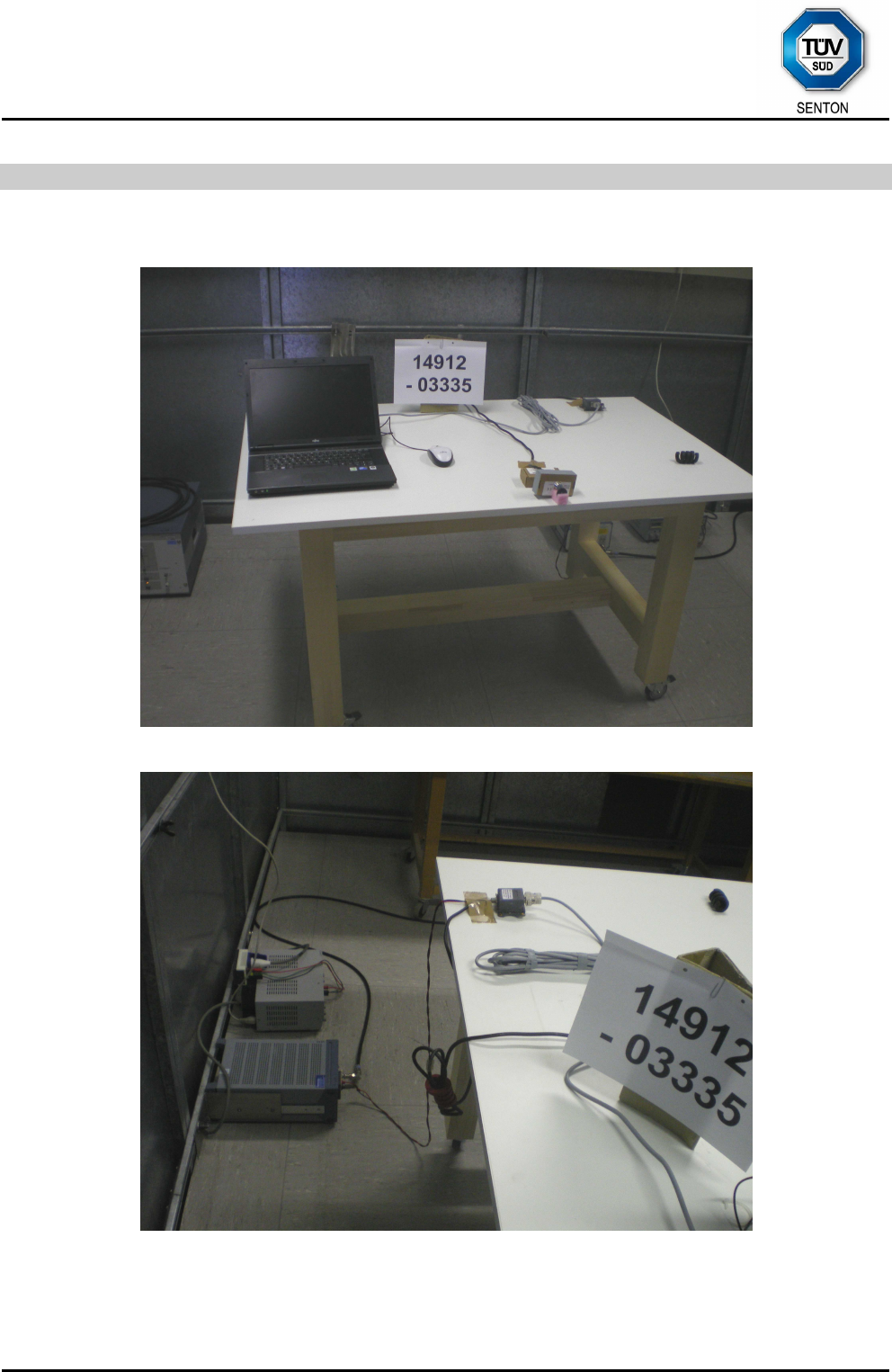
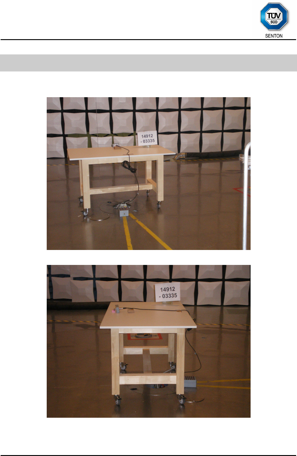
Test setup for conducted AC powerline emission measurement
TÜV SÜD SENTON GmbH
Äußere Frühlingstraße 45
94315 Straubing
Germany
Phone: +49 9421 5522-0
Fax: +49 9421 5522-99
Web: www.tuev-sued.de/senton
eMail: senton@tuev-sued.de
Test Report No. 14912-03335-1 (Edition 1) Page 19 of 59 Pages
Test setup for conducted AC powerline emission measurement
- continued -
TÜV SÜD SENTON GmbH
Äußere Frühlingstraße 45
94315 Straubing
Germany
Phone: +49 9421 5522-0
Fax: +49 9421 5522-99
Web: www.tuev-sued.de/senton
eMail: senton@tuev-sued.de
Test Report No. 14912-03335-1 (Edition 1) Page 20 of 59 Pages
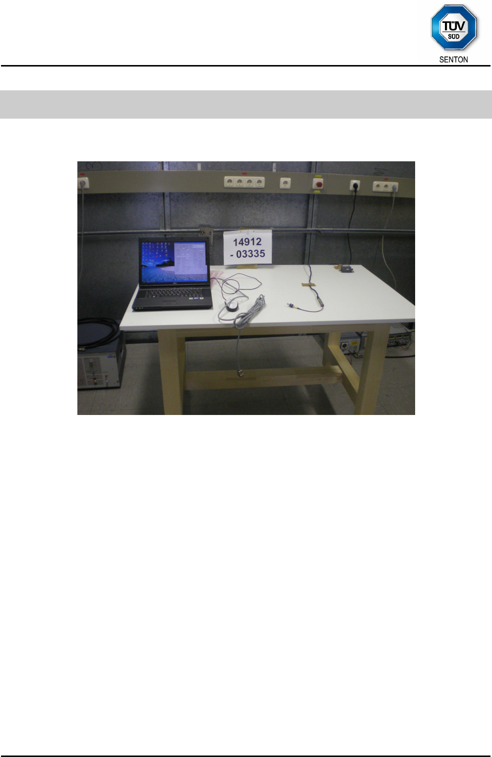
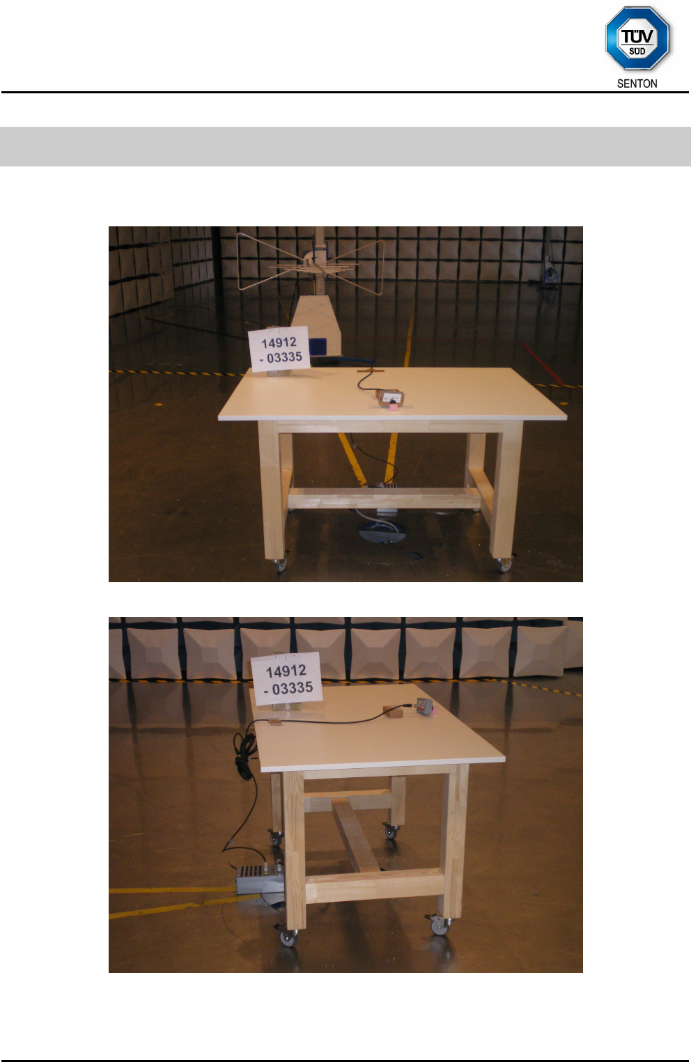
Test setup for radiated emission measurement 9 kHz – 30 MHz
TÜV SÜD SENTON GmbH
Äußere Frühlingstraße 45
94315 Straubing
Germany
Phone: +49 9421 5522-0
Fax: +49 9421 5522-99
Web: www.tuev-sued.de/senton
eMail: senton@tuev-sued.de
Test Report No. 14912-03335-1 (Edition 1) Page 21 of 59 Pages
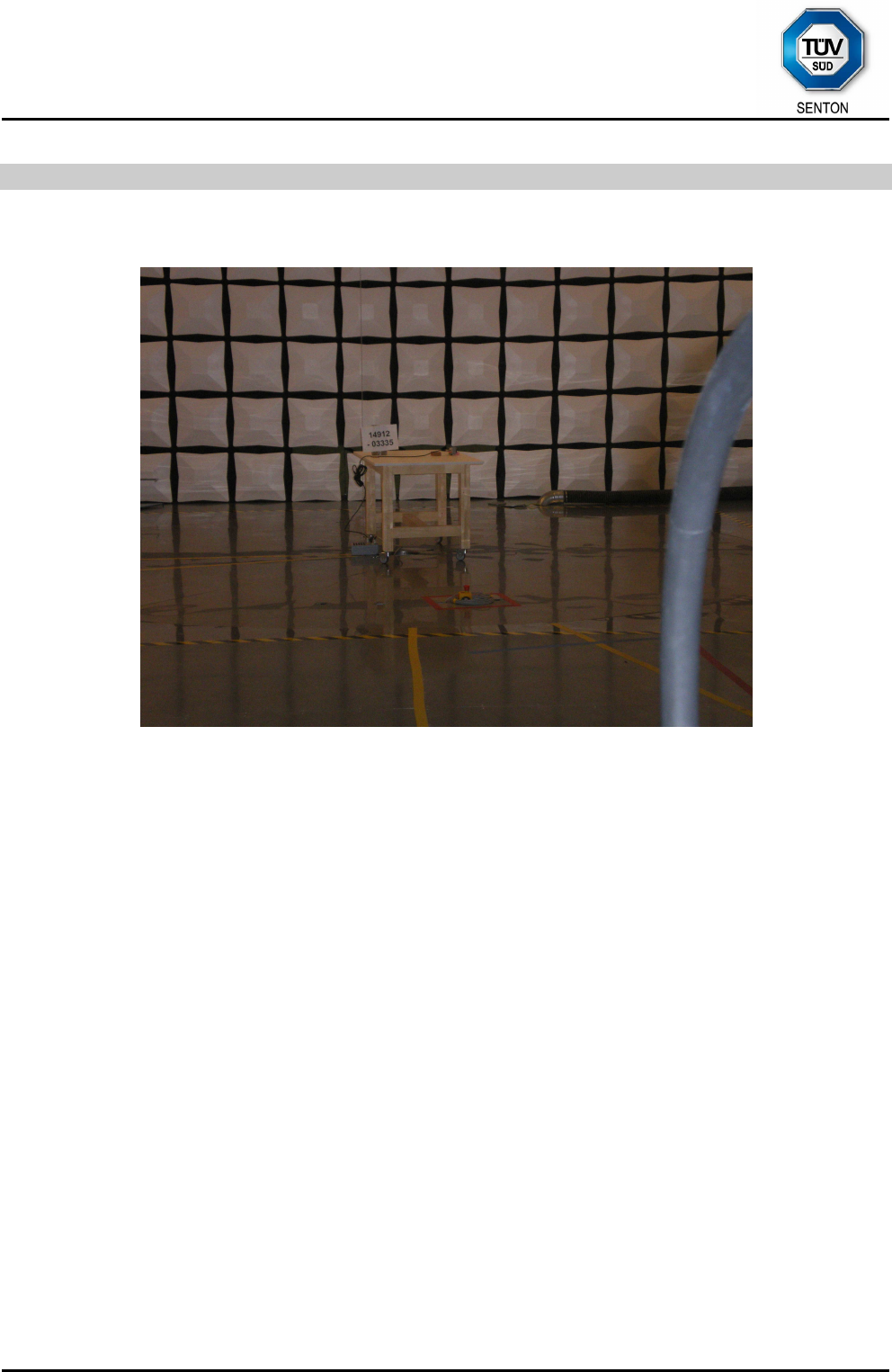
Test setup for radiated emission measurement
(alternate test site)
TÜV SÜD SENTON GmbH
Äußere Frühlingstraße 45
94315 Straubing
Germany
Phone: +49 9421 5522-0
Fax: +49 9421 5522-99
Web: www.tuev-sued.de/senton
eMail: senton@tuev-sued.de
Test Report No. 14912-03335-1 (Edition 1) Page 22 of 59 Pages
Test setup for radiated emission measurement
(alternate test site) - continued -
TÜV SÜD SENTON GmbH
Äußere Frühlingstraße 45
94315 Straubing
Germany
Phone: +49 9421 5522-0
Fax: +49 9421 5522-99
Web: www.tuev-sued.de/senton
eMail: senton@tuev-sued.de
Test Report No. 14912-03335-1 (Edition 1) Page 23 of 59 Pages
8 Test Results
FCC CFR 47 Parts 2 and 15
Section(s) Test Page Result
2.1046(a) Conducted output power --- Not applicable
2.202(a) Occupied bandwidth 25 Recorded
15.215(c) Bandwidth of the emission 29 Test passed
2.201, 2.202 Class of emission 31 Calculated
15.35(c) Pulse train measurement for pulsed operation --- Not applicable
15.205(a)
15.205(d)(7)
Restricted bands of operation ---5 Test passed
15.207 Conducted AC powerline emission
150 kHz to 30 MHz
32 Test passed
15.225(a)-(d) Spectrum Mask 35 Test passed
15.205(b)
15.215(b)
15.225(a)(d)
Radiated emission
9 kHz to 30 MHz
37 Test passed
15.205(b)
15.225(d)
Radiated emission
30 MHz to 1 GHz
39 Test passed
15.225(e) Carrier frequency stability 41 Test passed
5 See "Spectrum Mask" for the 13.36 to 13.41 MHz band. For all other restricted bands see "Radiated
Emission".
TÜV SÜD SENTON GmbH
Äußere Frühlingstraße 45
94315 Straubing
Germany
Phone: +49 9421 5522-0
Fax: +49 9421 5522-99
Web: www.tuev-sued.de/senton
eMail: senton@tuev-sued.de
Test Report No. 14912-03335-1 (Edition 1) Page 24 of 59 Pages
IC RSS-Gen Issue 3
Section(s) Test Page Result
4.8 Transmitter output power (conducted) --- Not applicable
4.6.1 Occupied Bandwidth 25 Recorded
8 Designation of emissions 31 Calculated
4.5 Pulsed operation --- Not applicable
7.2.2 Restricted bands and unwanted emission frequencies ---6 Test passed
7.2.4 Transmitter AC power lines conducted emissions
150 kHz to 30 MHz
32 Test passed
7.2.5 Unwanted emissions
9 kHz to 30 MHz
37 Test passed
7.2.5 Unwanted emissions
30 MHz to 1 GHz
39 Test passed
5.5 Exposure of Humans to RF Fields 44 Exempted from
SAR and RF
evaluation
IC RSS-210 Issue 8
Section(s) Test Page Result
A2.6 Spectrum Mask 35 Test passed
A.2.6 Unwanted emissions
9 kHz to 30 MHz
37 Test passed
A2.6 Unwanted emissions
30 MHz to 1 GHz
39 Test passed
A2.6 Carrier frequency stability 41 Test passed
6 See "Spectrum Mask" and "Unwanted emissions".
TÜV SÜD SENTON GmbH
Äußere Frühlingstraße 45
94315 Straubing
Germany
Phone: +49 9421 5522-0
Fax: +49 9421 5522-99
Web: www.tuev-sued.de/senton
eMail: senton@tuev-sued.de
Test Report No. 14912-03335-1 (Edition 1) Page 25 of 59 Pages
8.1 Occupied Bandwidth
Rules and specifications: CFR 47 Part 2, section 2.202(a)
ANSI C63.4, annex H.6
Guide: ANSI C63.4
Description: The occupied bandwidth according to CFR 47 Part 2, section 2.202(a), is
measured as the 99% emission bandwidth, i.e. below its lower and above its
upper frequency limits, the mean powers radiated are each equal to 0.5% of
the total mean power radiated by a given emission.
The occupied bandwidth according to ANSI C63.4, annex H.6; is measured
as the frequency range defined by the points that are 26 dB down relative to
the maximum level of the modulated carrier.
The resolution bandwidth of the spectrum analyzer shall be set to a value
greater than 5.0% of the allowed bandwidth. If no bandwidth specifications
are given, the following guidelines are used:
Fundamental frequency Minimum resolution bandwidth
9 kHz to 30 MHz 1 kHz
30 MHz to 1000 MHz 10 kHz
1000 MHz to 40 GHz 100 kHz
The video bandwidth shall be at least three times greater than the resolution
bandwidth.
Measurement procedure: Bandwidth Measurements (6.1)
Comment:
Date of test: December 22, 2010
Test site: Fully anechoic room, cabin no. 2
TÜV SÜD SENTON GmbH
Äußere Frühlingstraße 45
94315 Straubing
Germany
Phone: +49 9421 5522-0
Fax: +49 9421 5522-99
Web: www.tuev-sued.de/senton
eMail: senton@tuev-sued.de
Test Report No. 14912-03335-1 (Edition 1) Page 26 of 59 Pages
Occupied Bandwidth (99 %):
Att 0 dB
*
*
A
Offset 20 dB
LVL
Ref 70 dBµV
PS
2 kHz/Center 13.55944 MHz Span 20 kHz
*
3DB
RBW 1 kHz
DC
VBW 10 kHz
SGL
SWT 10 s
*
*1 R
M
CLRWR
-30
-20
-10
0
10
20
30
40
50
60
70
1
Marker 1 [T1 ]
39.23 dBµ
V
13.559280000 MHz
OBW 14.680000000 kHz
T1
Temp 1 [T1 OBW]
12.68 dBµ
V
13.552040000 MHz
T2
Temp 2 [T1 OBW]
13.12 dBµ
V
13.566720000 MHz
Date: 22.DEC.2010 13:46:20
Occupied Bandwidth (99 %): 14.68 kHz
TÜV SÜD SENTON GmbH
Äußere Frühlingstraße 45
94315 Straubing
Germany
Phone: +49 9421 5522-0
Fax: +49 9421 5522-99
Web: www.tuev-sued.de/senton
eMail: senton@tuev-sued.de
Test Report No. 14912-03335-1 (Edition 1) Page 27 of 59 Pages
Occupied Bandwidth (continued)
Rules and specifications: IC RSS-Gen Issue 3, section 4.6.1
Guide: IC RSS-Gen Issue 3, section 4.6.1
Description: If not specified in the applicable RSS the occupied bandwidth is measured as
the 99% emission bandwidth.
The span of the analyzer shall be set to capture all products of the
modulation process, including the emission skirts. The resolution bandwidth
shall be set to as close to 1% of the selected span as is possible without
being below 1%. The video bandwidth shall be set to 3 times the resolution
bandwidth.
The trace data points are recovered and are directly summed in linear terms.
The recovered amplitude data points, beginning at the lowest frequency, are
placed in a running sum until 0.5% of the total is reached and that frequency
recorded. The process is repeated for the highest frequency data points. This
frequency is also recorded. The span between the two recorded frequencies
is the occupied bandwidth.
Measurement procedure: Bandwidth Measurements (6.1)
Comment:
Date of test: December 22, 2010
Test site: Fully anechoic room, cabin no. 2

TÜV SÜD SENTON GmbH
Äußere Frühlingstraße 45
94315 Straubing
Germany
Phone: +49 9421 5522-0
Fax: +49 9421 5522-99
Web: www.tuev-sued.de/senton
eMail: senton@tuev-sued.de
Test Report No. 14912-03335-1 (Edition 1) Page 28 of 59 Pages
Occupied Bandwidth (99 %):
Att 0 dB
*
*
A
Offset 20 dB
LVL
Ref 70 dBµV
PS
2 kHz/Center 13.55944 MHz Span 20 kHz
*
3DB
RBW 1 kHz
DC
VBW 10 kHz
SGL
SWT 10 s
*
*1 R
M
CLRWR
-30
-20
-10
0
10
20
30
40
50
60
70
1
Marker 1 [T1 ]
39.23 dBµ
V
13.559280000 MHz
OBW 14.680000000 kHz
T1
Temp 1 [T1 OBW]
12.68 dBµ
V
13.552040000 MHz
T2
Temp 2 [T1 OBW]
13.12 dBµ
V
13.566720000 MHz
Date: 22.DEC.2010 13:46:20
Occupied Bandwidth (99 %): 14.68 kHz
TÜV SÜD SENTON GmbH
Äußere Frühlingstraße 45
94315 Straubing
Germany
Phone: +49 9421 5522-0
Fax: +49 9421 5522-99
Web: www.tuev-sued.de/senton
eMail: senton@tuev-sued.de
Test Report No. 14912-03335-1 (Edition 1) Page 29 of 59 Pages
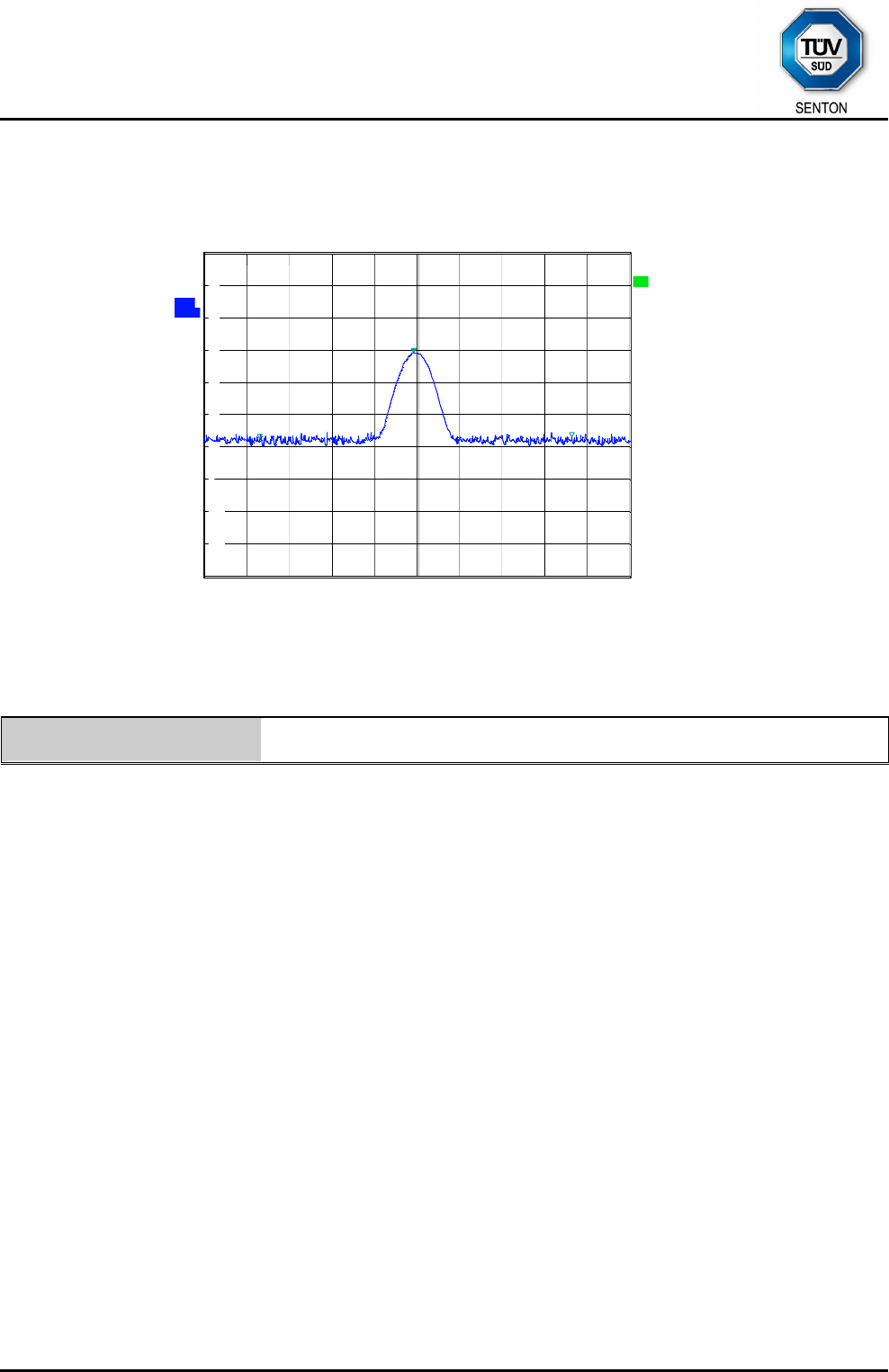
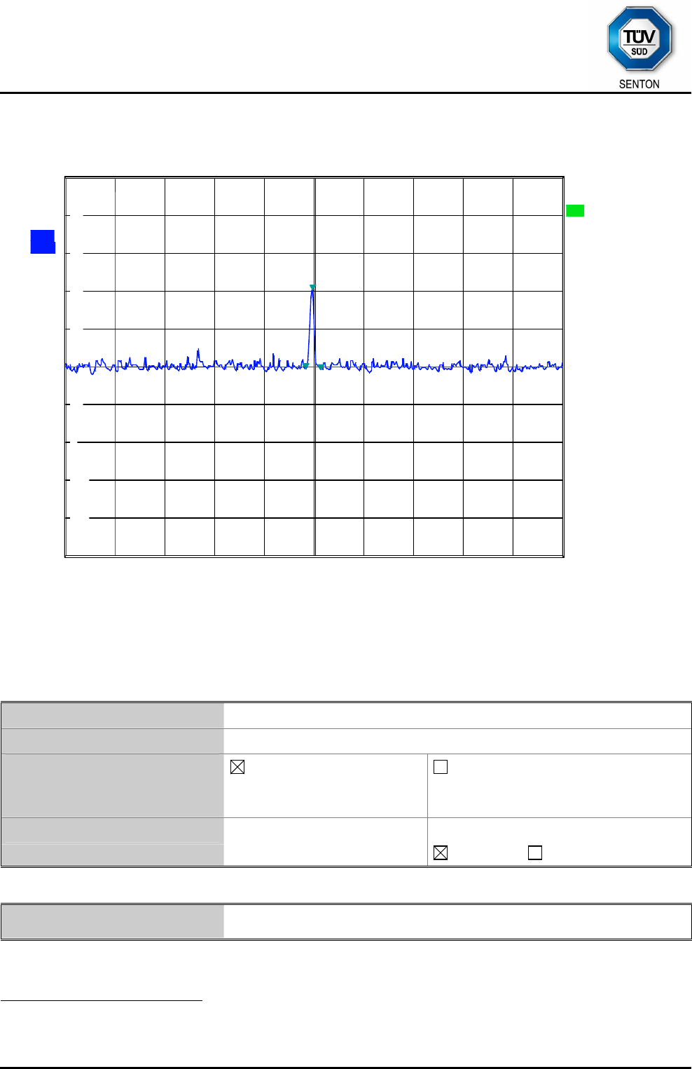
8.2 Bandwidth of the Emission
Rules and specifications: CFR 47 Part 15, section 15.215(c)
Guide: ANSI C63.4
Description: The 20 dB bandwidth of the emission is measured as the frequency range
defined by the points that are 20 dB down relative to the maximum level of
the modulated carrier.
For intentional radiators operating under the alternative provisions to the
general emission limits the requirement to contain the 20 dB bandwidth of
the emission within the specified frequency band includes the effects from
frequency sweeping, frequency hopping and other modulation techniques
that may be employed as well as the frequency stability of the transmitter
over expected variations in temperature and supply voltage. If a frequency
stability is not specified in the regulations, it is recommended that the
fundamental emission be kept within at least the central 80% of the
permitted band in order to minimize the possibility of out-of-band
operation.
The resolution bandwidth of the spectrum analyzer shall be set to a value
greater than 5.0% of the allowed bandwidth. If no bandwidth specifications
are given, the following guidelines are used:
Fundamental frequency Minimum resolution bandwidth
9 kHz to 30 MHz 1 kHz
30 MHz to 1000 MHz 10 kHz
1000 MHz to 40 GHz 100 kHz
The video bandwidth shall be at least three times greater than the
resolution bandwidth.
Measurement procedure: Bandwidth Measurements (6.1)
Comment:
Date of test: December 22, 2010
Test site: Fully anechoic room, cabin no. 2
TÜV SÜD SENTON GmbH
Äußere Frühlingstraße 45
94315 Straubing
Germany
Phone: +49 9421 5522-0
Fax: +49 9421 5522-99
Web: www.tuev-sued.de/senton
eMail: senton@tuev-sued.de
Test Report No. 14912-03335-1 (Edition 1) Page 30 of 59 Pages
Att 0 dB
*
A
Offset 20 dB
LVL
Ref 70 dBµV
PS
20 kHz/Center 13.56 MHz Span 200 kHz
*
3DB
RBW 1 kHz
SWT 200 ms
DC
VBW 3 kHz
1 PK
V
IEW
-30
-20
-10
0
10
20
30
40
50
60
70
1
Marker 1 [T1 ]
40.19 dBµ
V
13.559600000 MHz
2
Marker 2 [T1 ]
19.37 dBµ
V
13.556800000 MHz
3
Marker 3 [T1 ]
19.20 dBµ
V
13.562800000 MHz
D1 20.11 dBµV
Date: 22.DEC.2010 13:45:20
Permitted frequency band: 13.110 - 14.010 MHz
20 dB bandwidth: 6.0 kHz
Carrier frequency stability: specified not specified
Maximum frequency tolerances: +0.095 kHz
-0.077 kHz
Bandwidth of the emission: 6.2 kHz within permitted frequency band7:
yes no
Test Result: Test passed
7 If a frequency stability is not specified, it is recommended that the fundamental emission is kept within at least
the central 80% of the permitted band in order to minimize the possibility of out-of-band operation.
TÜV SÜD SENTON GmbH
Äußere Frühlingstraße 45
94315 Straubing
Germany
Phone: +49 9421 5522-0
Fax: +49 9421 5522-99
Web: www.tuev-sued.de/senton
eMail: senton@tuev-sued.de
Test Report No. 14912-03335-1 (Edition 1) Page 31 of 59 Pages
8.3 Designation of Emissions
Rules and specifications: CFR 47 Part 2, sections 2.201 and 2.202
IC RSS-Gen Issue 3, section 8
Guide: ANSI C63.4 / TRC-43
Type of modulation: Amplitude Modulation
Bn = Necessary Bandwidth Bn = 2BK
B = Modulation rate B = 5 kHz
K = Overall numerical factor K = 1
Calculation: Bn = 2 · (5 kHz) · 1 = 10 kHz
Designation of Emissions: 10K0A1D
TÜV SÜD SENTON GmbH
Äußere Frühlingstraße 45
94315 Straubing
Germany
Phone: +49 9421 5522-0
Fax: +49 9421 5522-99
Web: www.tuev-sued.de/senton
eMail: senton@tuev-sued.de
Test Report No. 14912-03335-1 (Edition 1) Page 32 of 59 Pages
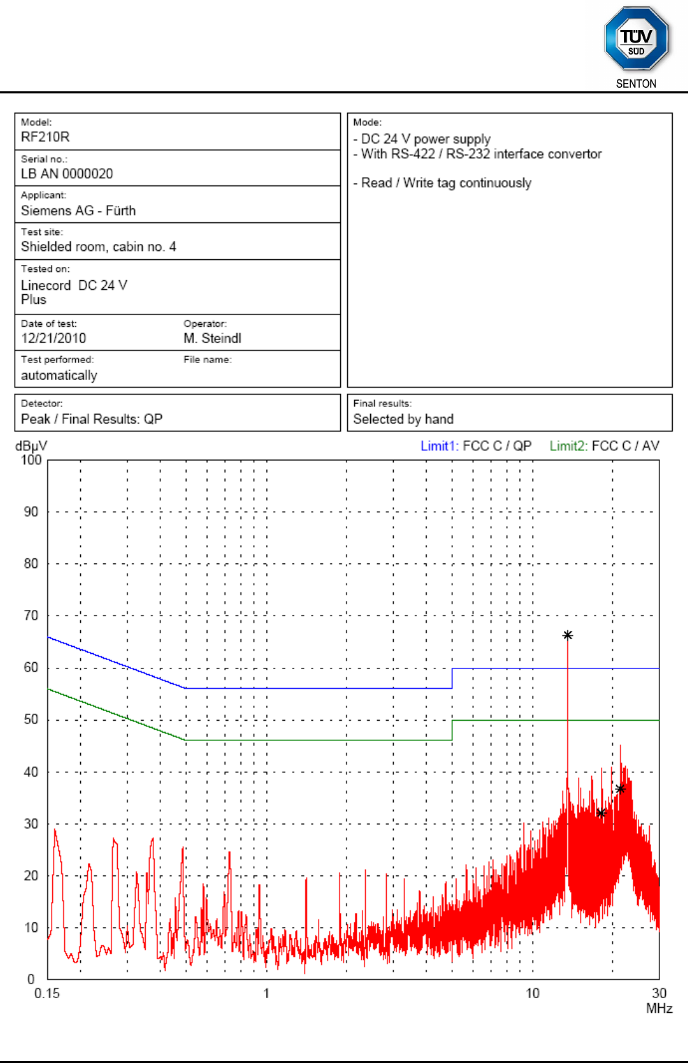
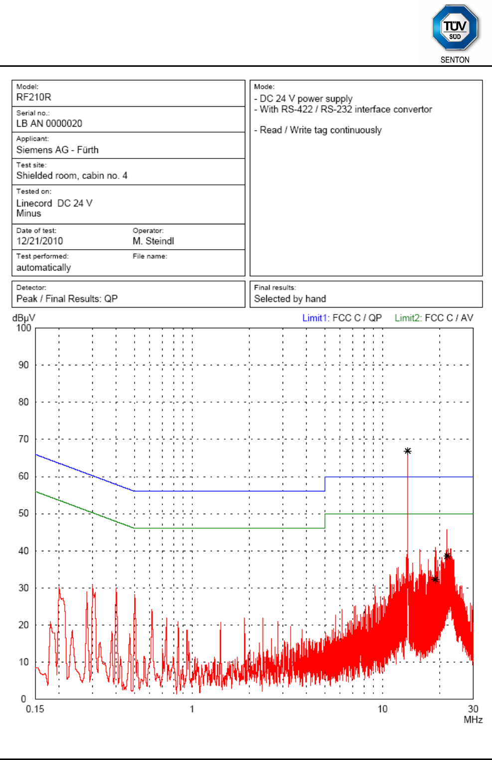
8.4 Conducted Powerline Emission Measurement 150 kHz to 30 MHz
Rules and specifications: CFR 47 Part 15, section 15.207
IC RSS-Gen Issue 3, section 7.2.4
Guide: ANSI C63.4 / CISPR 22
Limit: Conducted Limit (dBµV)
Frequency of Emission
(MHz) Quasi-peak Average
0.15 - 0.5 66 to 56 56 to 46
0.5 - 5 56 46
5 - 30 60 50
Measurement procedure: Conducted AC Powerline Emission (6.2)
Test Result: Test passed
TÜV SÜD SENTON GmbH
Äußere Frühlingstraße 45
94315 Straubing
Germany
Phone: +49 9421 5522-0
Fax: +49 9421 5522-99
Web: www.tuev-sued.de/senton
eMail: senton@tuev-sued.de
Test Report No. 14912-03335-1 (Edition 1) Page 33 of 59 Pages
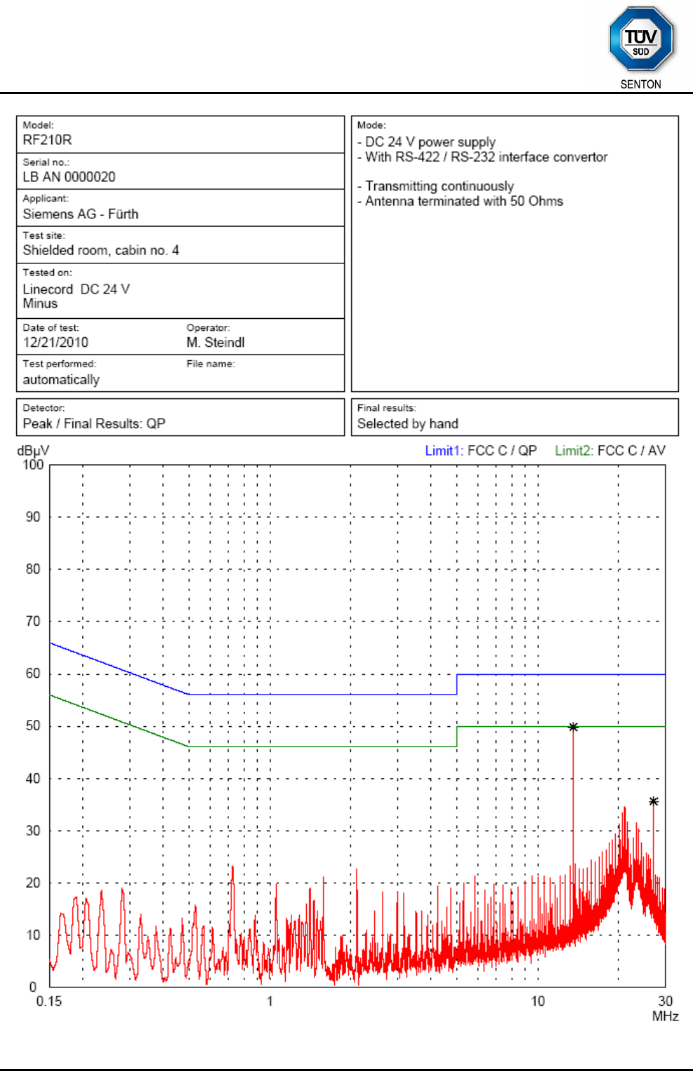
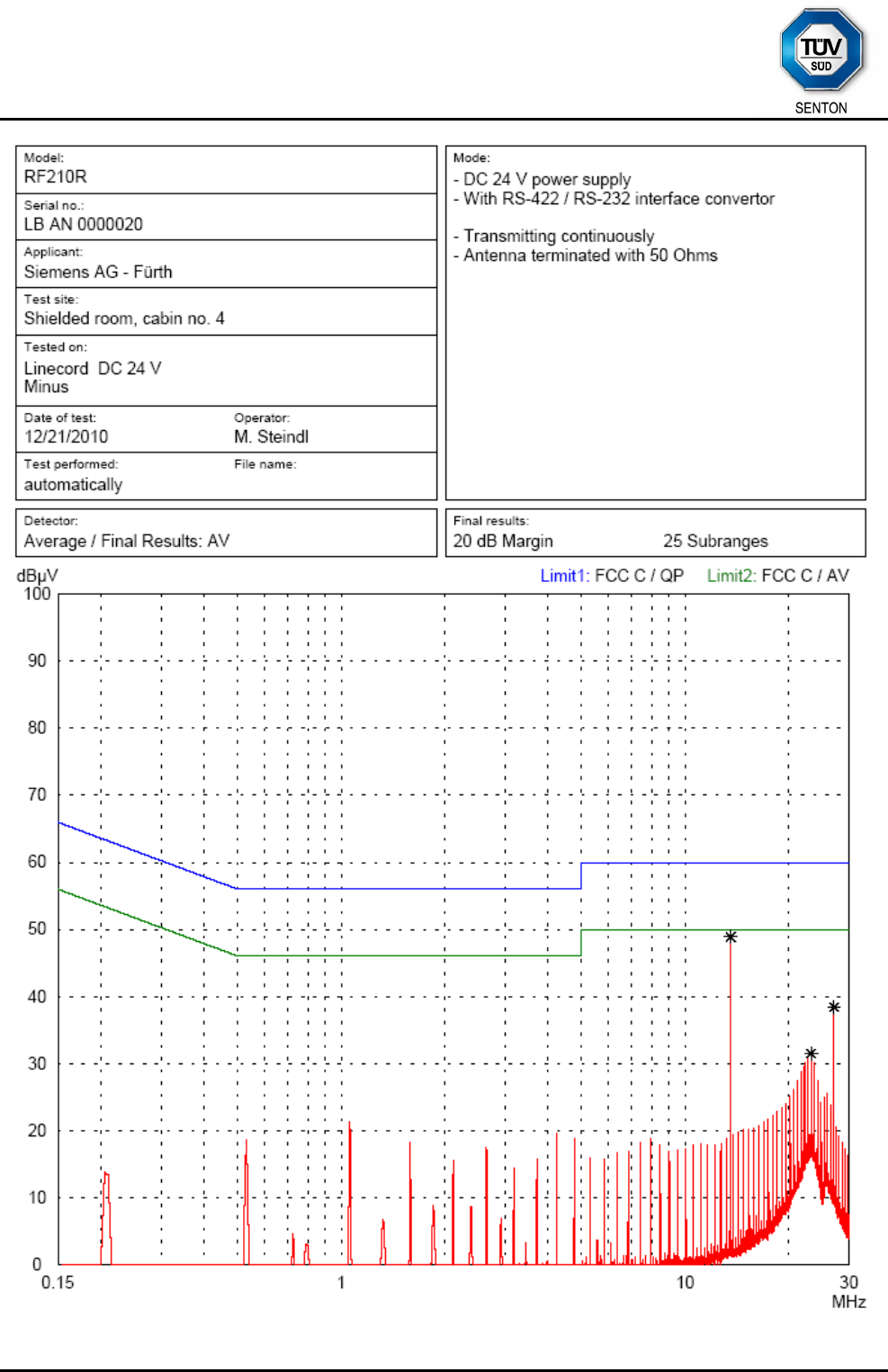
Comment: Reading tag continuously
Date of test: December 21, 2010
Test site: Shielded room, cabin no. 4
Test Result: Test passed - Carrier frequency excluded
Tested on: Plus
Frequency Detector Reading Correction Final Limit Margin
Value Factor Value
(MHz) (dBµV) (dB) (dBµV) (dBµV) (dB)
13.560 Quasi-Peak 66.3 0.0 66.3 60.0 -6.3
18.145 Quasi-Peak 32.1 0.0 32.1 60.0 27.9
21.380 Quasi-Peak 36.7 0.0 36.7 60.0 23.3
Tested on: Minus
Frequency Detector Reading Correction Final Limit Margin
Value Factor Value
(MHz) (dBµV) (dB) (dBµV) (dBµV) (dB)
13.560 Quasi-Peak 66.8 0.0 66.8 60.0 -6.8
18.955 Quasi-Peak 32.2 0.0 32.2 60.0 27.8
21.840 Quasi-Peak 38.6 0.0 38.6 60.0 21.4
Sample calculation of final values:
Final Value (dBµV) = Reading Value (dBµV) + Correction Factor (dB)
TÜV SÜD SENTON GmbH
Äußere Frühlingstraße 45
94315 Straubing
Germany
Phone: +49 9421 5522-0
Fax: +49 9421 5522-99
Web: www.tuev-sued.de/senton
eMail: senton@tuev-sued.de
Test Report No. 14912-03335-1 (Edition 1) Page 34 of 59 Pages
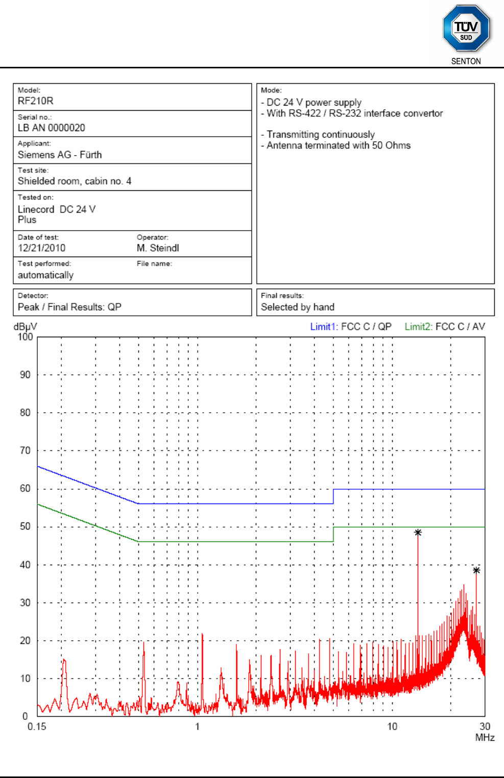
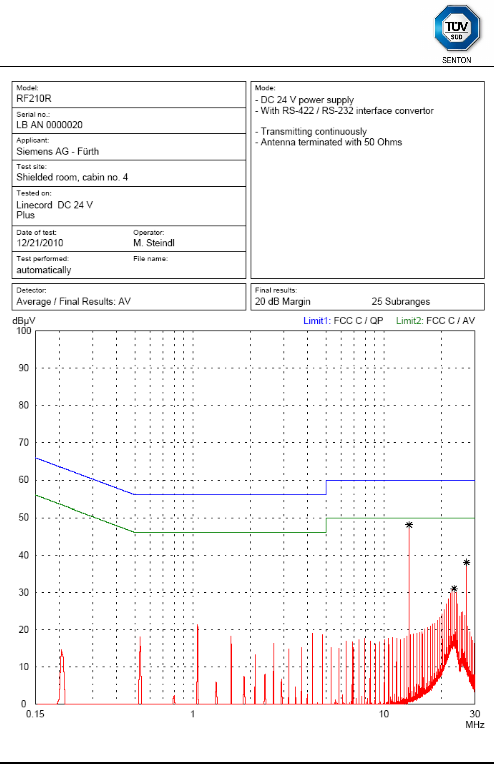
Comment: Transmitting continuously.
Internal antenna connector terminated with 50 Ohms
Date of test: December 21, 2010
Test site: Shielded room, cabin no. 4
Test Result: Test passed
Tested on: Plus
Frequency Detector Reading Correction Final Limit Margin
Value Factor Value
(MHz) (dBµV) (dB) (dBµV) (dBµV) (dB)
13.560 Quasi-Peak 48.5 0.0 48.5 60.0 11.5
13.560
A
verage 48.9 0.0 48.9 50.0 1.1
23.305 Average 31.5 0.0 31.5 50.0 18.5
27.120 Quasi-Peak 38.5 0.0 38.5 60.0 21.5
27.120
A
verage 38.4 0.0 38.4 50.0 11.6
Tested on: Minus
Frequency Detector Reading Correction Final Limit Margin
Value Factor Value
(MHz) (dBµV) (dB) (dBµV) (dBµV) (dB)
13.560 Quasi-Peak 49.8 0.0 49.8 60.0 10.2
13.560
A
verage 48.1 0.0 48.1 50.0 1.9
23.325 Average 31.0 0.0 31.0 50.0 19.0
27.120 Quasi-Peak 35.6 0.0 35.6 60.0 24.4
27.120
A
verage 38.0 0.0 38.0 50.0 12.0
Sample calculation of final values:
Final Value (dBµV) = Reading Value (dBµV) + Correction Factor (dB)

TÜV SÜD SENTON GmbH
Äußere Frühlingstraße 45
94315 Straubing
Germany
Phone: +49 9421 5522-0
Fax: +49 9421 5522-99
Web: www.tuev-sued.de/senton
eMail: senton@tuev-sued.de
Test Report No. 14912-03335-1 (Edition 1) Page 35 of 59 Pages
8.5 Spectrum Mask
Rules and specifications: CFR 47 Part 15, section 15.225(a)-(d)
IC RSS-210 Issue 8, section A2.6
Guide: ANSI C63.4
Description: Compliance with the spectrum mask is tested using a spectrum analyzer with
resolution bandwidth set to a 1 kHz for the band 13.553 to 13.567 MHz and to
10 kHz outside this band. The video bandwidth shall be at least three times
greater than the resolution bandwidth.
Limit: Frequency of
Emission
(MHz)
Field
Strength
(µV/m)
Field
Strength
(dBµV/m)
Measurement
Distance d
(meters)
1.705 - 13.110 30 29.5 30
13.110 - 13.410 106 40.5 30
13.410 - 13.553 334 50.5 30
13.553 - 13.567 15848 84.0 30
13.567 - 13.710 334 50.5 30
13.710 - 14.010 106 40.5 30
14.010 - 30.000 30 29.5 30
Measurement procedure: Radiated Emission Measurement 9 kHz to 30 MHz (6.3)
Comment:
Date of test: December 22, 2010
Test site: Fully anechoic room, cabin no. 2
Test distance: 3 meters
Extrapolation Factor: 40 dB/decade
TÜV SÜD SENTON GmbH
Äußere Frühlingstraße 45
94315 Straubing
Germany
Phone: +49 9421 5522-0
Fax: +49 9421 5522-99
Web: www.tuev-sued.de/senton
eMail: senton@tuev-sued.de
Test Report No. 14912-03335-1 (Edition 1) Page 36 of 59 Pages
Test Result: Test passed
Att 0 dB
*
A
PS
DC
Ref 107 dBµV
Offset 20 dB
Center 13.56 MHz Span 1 MHz100 kHz/
LVL
*
3DB
RBW 10 kHz
VBW 30 kHz
SWT 10 ms
1 PK
MAXH
10
20
30
40
50
60
70
80
90
100
1
Marker 1 [T1 ]
41.99 dBµ
V
13.560000000 MHz
FCC225_3
Date: 22.DEC.2010 13:41:21
Att 0 dB
*
A
PS
DC
Ref 107 dBµV
Offset 20 dB
Center 13.56 MHz Span 1 MHz100 kHz/
LVL
1 PK
MAXH
*
3DB
RBW 1 kHz
VBW 3 kHz
SWT 1 s
10
20
30
40
50
60
70
80
90
100
1
Marker 1 [T1 ]
40.11 dBµ
V
13.560000000 MHz
FCC225_3
Date: 22.DEC.2010 13:41:56
TÜV SÜD SENTON GmbH
Äußere Frühlingstraße 45
94315 Straubing
Germany
Phone: +49 9421 5522-0
Fax: +49 9421 5522-99
Web: www.tuev-sued.de/senton
eMail: senton@tuev-sued.de
Test Report No. 14912-03335-1 (Edition 1) Page 37 of 59 Pages
8.6 Radiated Emission Measurement 9 kHz to 30 MHz
Rules and specifications: CFR 47 Part 15, sections 15.205 and 15.225(a)-(d)
IC RSS-Gen Issue 3, section 7.2.5 / IC RSS-210 Issue 8, section A2.6
Guide: ANSI C63.4
Limit: Frequency of
Emission
(MHz)
Field
Strength
(µV/m)
Field
Strength
(dBµV/m)
Measurement
Distance d
(meters)
0.009 - 0.490 2400/F(kHz) 67.6 - 20 ⋅ log(F(kHz)) 300
0.490 - 1.705 24000/F(kHz) 87.6 - 20 ⋅ log(F(kHz)) 30
1.705 - 13.110 30 29.5 30
13.110 - 13.410 106 40.5 30
13.410 - 13.553 334 50.5 30
13.553 - 13.567 15848 84.0 30
13.567 - 13.710 334 50.5 30
13.710 - 14.010 106 40.5 30
14.010 - 30.000 30 29.5 30
Additionally, the level of any unwanted emissions shall not exceed the level of
the fundamental emission.
Measurement procedure: Radiated Emission Measurement 9 kHz to 30 MHz (6.3)
Comment:
Date of test: December 22, 2010
Test site: Open field test site
Test Result: Test passed
Extrapolation factor:
Frequency Detector Reading Correction Extrapolation Pulse Train Final Limit Margin
d1 d Value Factor Factor Correction Value
(MHz) (m) (m) (dBµV) (dB/m) (dB) (dB) (dBµV/m) (dBµV/m) (dB)
0.35700 Average 10 300 27.8 20.0 -59.1 -11.3 16.6 27.9
13.56000 Quasi-Peak 10 30 9.1 20.0 -19.1 10.0 84.0 74.0
Distance
-40 dB/decade

TÜV SÜD SENTON GmbH
Äußere Frühlingstraße 45
94315 Straubing
Germany
Phone: +49 9421 5522-0
Fax: +49 9421 5522-99
Web: www.tuev-sued.de/senton
eMail: senton@tuev-sued.de
Test Report No. 14912-03335-1 (Edition 1) Page 38 of 59 Pages
Sample calculation of final values:
Extrapolation Factor (dB) = (Log(d) - Log(d1)) · Extrapolation Factor (dB/decade)
Final Value (dBµV/m) = Reading Value d1 (dBµV) + Correction Factor (dB/m)
+ Extrapolation Factor (dB) + Pulse Train Correction (dB)
Note: Extrapolation factor (dB) and final value (dBµV/m) are relating to distance d.
TÜV SÜD SENTON GmbH
Äußere Frühlingstraße 45
94315 Straubing
Germany
Phone: +49 9421 5522-0
Fax: +49 9421 5522-99
Web: www.tuev-sued.de/senton
eMail: senton@tuev-sued.de
Test Report No. 14912-03335-1 (Edition 1) Page 39 of 59 Pages
8.7 Radiated Emission Measurement 30 MHz to 1 GHz
Rules and specifications: CFR 47 Part 15, sections 15.205(b) and 15.225(d)
IC RSS-Gen Issue 3, section 7.2.5 / IC RSS-210 Issue 8, section A2.6
Guide: ANSI C63.4
Limit: Frequency of Emission
(MHz)
Field Strength
(µV/m)
Field Strength
(dBµV/m)
30 - 88 100 40.0
88 - 216 150 43.5
216 - 960 200 46.0
Above 960 500 54.0
Additionally, the level of any unwanted emissions shall not exceed the level of
the fundamental emission.
Measurement procedures: Radiated Emission at Alternative Test Site (6.4)
Comment:
Date of test: December 22, 2010
Test site: Frequencies ≤ 1 GHz: Semi-anechoic room, cabin no. 8
Frequencies > 1 GHz: Fully anechoic room, cabin no. 2
Test distance: 3 meters
Test Result: Test passed
TÜV SÜD SENTON GmbH
Äußere Frühlingstraße 45
94315 Straubing
Germany
Phone: +49 9421 5522-0
Fax: +49 9421 5522-99
Web: www.tuev-sued.de/senton
eMail: senton@tuev-sued.de
Test Report No. 14912-03335-1 (Edition 1) Page 40 of 59 Pages
Frequenc
y
A
ntenna Detecto
r
Receive
r
Correction Pulse Train Final Limit Margin
Polarization Reading Facto
r
Correction Value
(MHz) (dBµV) (dB/m) (dB) (dBµV/m) (dBµV/m) (dB)
40.700 vertical Quasi-Peak 22.8 14.4 37.2 40.0 2.8
43.180 vertical Quasi-Peak 11.0 14.5 25.5 40.0 14.5
94.900 horizontal Quasi-Peak 23.9 12.6 36.5 43.5 7.0
101.960 horizontal Quasi-Peak 7.0 13.1 20.1 43.5 23.4
108.460 horizontal Quasi-Peak 12.5 12.9 25.4 43.5 18.1
122.020 horizontal Quasi-Peak 16.9 11.2 28.1 43.5 15.4
162.700 horizontal Quasi-Peak 18.2 10.1 28.3 43.5 15.2
189.820 horizontal Quasi-Peak 18.0 11.9 29.9 43.5 13.6
216.940 horizontal Quasi-Peak 22.0 12.6 34.6 46.0 11.4
338.980 horizontal Quasi-Peak 16.4 15.9 32.3 46.0 13.7
366.100 horizontal Quasi-Peak 15.1 16.4 31.5 46.0 14.5
488.140 vertical Quasi-Peak 14.6 18.4 33.0 46.0 13.0
989.840 horizontal Quasi-Peak 10.3 25.2 35.5 54.0 18.5
Sample calculation of final values:
Final Value (dBµV/m) = Reading Value (dBµV) + Correction Factor (dB/m)
+ Pulse Train Correction (dB)
TÜV SÜD SENTON GmbH
Äußere Frühlingstraße 45
94315 Straubing
Germany
Phone: +49 9421 5522-0
Fax: +49 9421 5522-99
Web: www.tuev-sued.de/senton
eMail: senton@tuev-sued.de
Test Report No. 14912-03335-1 (Edition 1) Page 41 of 59 Pages
8.8 Carrier Frequency Stability
Rules and specifications: CFR 47 Part 15, section 15.225(e)
IC RSS-Gen Issue 3, section 4.7 and IC RSS-210 Issue 8, section A2.6
Guide: ANSI C63.4
Limit: The frequency tolerance of the carrier signal shall be maintained within ±0.01
% (±100 ppm) of the carrier frequency under nominal conditions.
Temperature range: -20°C to +50°C (at normal supply voltage)
Voltage range: 85% to 115% of the rated supply voltage (at a temperature of +20°C)
Measurement procedure: Carrier Frequency Stability (6.5)
Comment:
Date of test: January 18, 2011
TÜV SÜD SENTON GmbH
Äußere Frühlingstraße 45
94315 Straubing
Germany
Phone: +49 9421 5522-0
Fax: +49 9421 5522-99
Web: www.tuev-sued.de/senton
eMail: senton@tuev-sued.de
Test Report No. 14912-03335-1 (Edition 1) Page 42 of 59 Pages
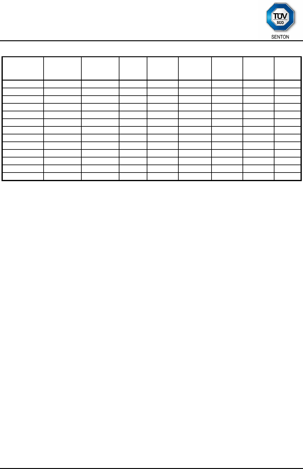
8.8.1 Carrier Frequency Stability vs. Temperature
Supply voltage: 24 V Nominal frequenc
y
:
Temperature Frequenc
y
Upper Limi
t
Lower Limit Mar
g
in
(
°C
)
(
MHz
)
(
Hz
)
(
ppm
)
(
ppm
)
(
ppm
)
(
ppm
)
-20 13.559511 82 6.0 +100.0 -100.0 94.0
-10 13.559524 9
5
7.0 +100.0 -100.0 93.0
±0 13.559503 74 5.5 +100.0 -100.0 94.
5
+10 13.559474 4
5
3.3 +100.0 -100.0 96.7
+20 13.559429 0 0.0 +100.0 -100.0 100.0
+30 13.559393 -36 -2.7 +100.0 -100.0 97.3
+40 13.559360 -69 -5.1 +100.0 -100.0 94.9
+50 13.559352 -77 -5.7 +100.0 -100.0 94.3
Frequency Tolerance
13.559429 MHz
-150.0
-100.0
-50.0
0.0
50.0
100.0
150.0
-20 -10 ±0 +10 +20 +30 +40 +50
Temperature (°C)
Frequency Tolerance (ppm)
Frequency Tolerance Upper Limit Lower Limit
Test Result: Test passed
TÜV SÜD SENTON GmbH
Äußere Frühlingstraße 45
94315 Straubing
Germany
Phone: +49 9421 5522-0
Fax: +49 9421 5522-99
Web: www.tuev-sued.de/senton
eMail: senton@tuev-sued.de
Test Report No. 14912-03335-1 (Edition 1) Page 43 of 59 Pages
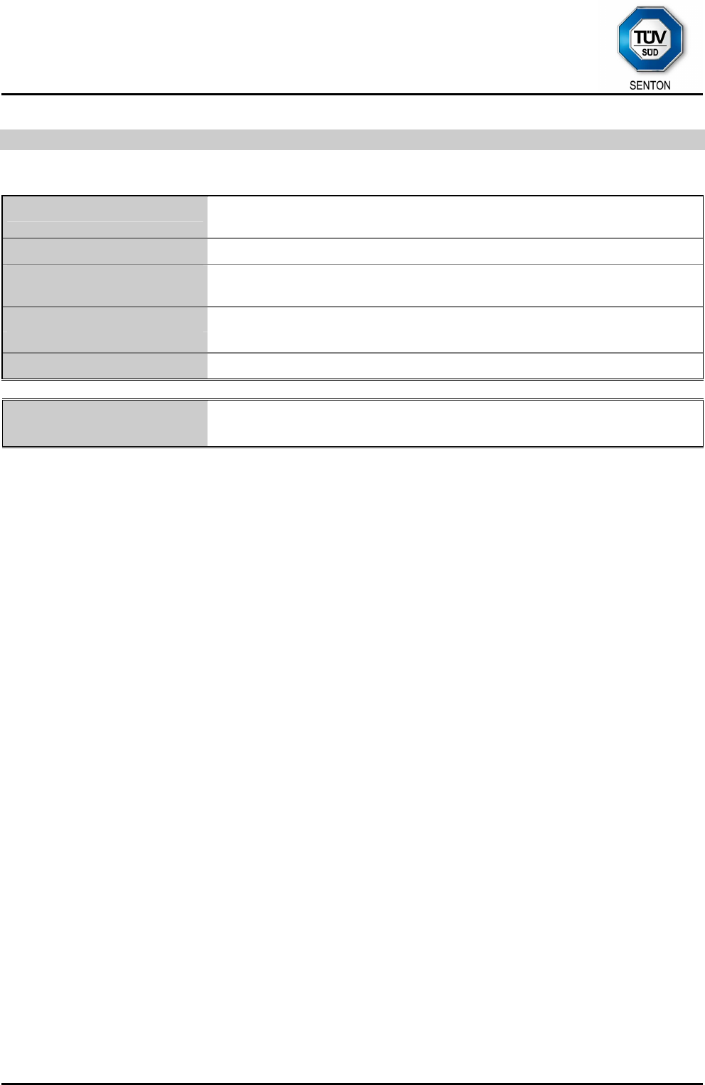
8.8.2 Carrier Frequency Stability vs. Supply Voltage
Temperature: +20 °C Batter
y
End Point: 1 V
Nominal frequency:
Suppl
y
Volta
g
e Frequenc
y
Upper Limi
t
Lower Limit Mar
g
in
(
V
)
(
MHz
)
(
Hz
)
(pp
m
)
(pp
m
)
(pp
m
)
(pp
m
)
28 13.559429 00.0 +100.0 -100.0 100.0
26 13.559429 00.0 +100.0 -100.0 100.0
25 13.559429 00.0 +100.0 -100.0 100.0
24 13.559429 00.0 +100.0 -100.0 100.0
23 13.559429 00.0 +100.0 -100.0 100.0
22 13.559430 10.1 +100.0 -100.0 99.9
20 13.559430 10.1 +100.0 -100.0 99.9
Frequency Tolerance
13.559429 MHz
-150.0
-100.0
-50.0
0.0
50.0
100.0
150.0
28 26 25 24 23 22 20
Supply Voltage (V)
Frequency Tolerance (ppm)
Frequency Tolerance Upper Limit Lower Limit
Test Result: Test passed
TÜV SÜD SENTON GmbH
Äußere Frühlingstraße 45
94315 Straubing
Germany
Phone: +49 9421 5522-0
Fax: +49 9421 5522-99
Web: www.tuev-sued.de/senton
eMail: senton@tuev-sued.de
Test Report No. 14912-03335-1 (Edition 1) Page 44 of 59 Pages
8.9 Exposure of Humans to RF Fields
Rules and specifications: IC RSS-Gen Issue 3, section 5.5
Guide: IC RSS-102 Issue 4, section 2.5
Exposure of Humans to RF Fields
Applicable
D
eclared by
applicant
Measured
Exemption
The antenna is
detachable
The conducted output power (CP in watts) is measured at the antenna
connector:
CP = ................ W
The effective isotropic radiated power (EIRP in watts) is calculated using
the numerical antenna gain: G= ................
EIRPCPGEIRP ⇒⋅= = ................ W
the field strength8 in V/m: FS = ................ V/m
EIRP
DFS
EIRP ⇒
⋅
=
30
)( 2
= ................ W
with:
Distance between the antennas in m: D= ................ m
not detachable
A field strength measurement is used to determine the effective isotropic
radiated power (EIRP in watts) given by8:
EIRP
DFS
EIRP ⇒
⋅
=
30
)( 2
= 2.92 nW
with:
Field strength in V/m: FS = 98.86 µV/m
Distance between the two antennas in m: D= 3 m
Selection of output power
The output power TP is the higher of the conducted or effective isotropic radiated
power (e.i.r.p.):
TP = 2.92 nW
8 The conversion formula is valid only for properly matched antennas. In other cases the transmitter output
power may have to be measured by a terminated measurement when applying the exemption clauses.
If an open area test site is used for field strength measurement, the effect due to the metal ground reflecting
plane should be subtracted from the maximum field strength value in order to reference it to free space, before
calculating TP.
TÜV SÜD SENTON GmbH
Äußere Frühlingstraße 45
94315 Straubing
Germany
Phone: +49 9421 5522-0
Fax: +49 9421 5522-99
Web: www.tuev-sued.de/senton
eMail: senton@tuev-sued.de
Test Report No. 14912-03335-1 (Edition 1) Page 45 of 59 Pages
Exposure of Humans to RF Fields (continued)
Applicable
D
eclared by
applicant
Measured
Exemption
Separation distance between the user and the transmitting device is
less than or equal to 20 cm greater than 20 cm
Transmitting device is
in the vicinity of the human head body-worn
SAR evaluation
SAR evaluation is required if the separation distance between the user and the
device is less than or equal to 20 cm.
The device operates from 3 kHz up to 1 GHz inclusively and with output power
(i.e. the higher of the conducted or equivalent isotropically radiated power
(e.i.r.p.) source-based, time-averaged output power) that is less than or equal to
200 mW for general public use and 1000 mW for controlled use.
;
The device operates above 1 GHz and up to 2.2 GHz inclusively and with output
power (i.e. the higher of the conducted or radiated (e.i.r.p.) source-based, time-
averaged output power) that is less than or equal to 100 W for general public
use and 500 W for controlled use.
The device operates above 2.2 GHz and up to 3 GHz inclusively and with output
power (i.e. the higher of the conducted or radiated (e.i.r.p.) source-based, time-
averaged output power) that is less than or equal to 20 mW for general public
use and 100 mW for controlled use.
The device operates above 3 GHz and up to 6 GHz inclusively and with output
power (i.e. the higher of the conducted or radiated (e.i.r.p.) source-based, time-
averaged output power) that is less than or equal to 10 mW for general public
use and 50 mW for controlled use.
SAR evaluation is documented in test report no. ............................
RF exposure evaluation
RF exposure evaluation is required if the separation distance between the user and
the device is greater than 20 cm.
The device operates below 1.5 GHz and the maximum e.i.r.p. of the device is
equal to or less than 2.5 W.
The device operates at or above 1.5 GHz and the maximum e.i.r.p. of the
device is equal to or less than 5 W.
RF exposure evaluation is documented in test report no. ............................
TÜV SÜD SENTON GmbH
Äußere Frühlingstraße 45
94315 Straubing
Germany
Phone: +49 9421 5522-0
Fax: +49 9421 5522-99
Web: www.tuev-sued.de/senton
eMail: senton@tuev-sued.de
Test Report No. 14912-03335-1 (Edition 1) Page 46 of 59 Pages
9 Referenced Regulations
All tests were performed with reference to the following regulations and standards:
CFR 47 Part 2 Code of Federal Regulations Part 2 (Frequency
allocation and radio treaty matters; General rules and
regulations) of the Federal Communication
Commission (FCC)
October 1, 2010
CFR 47 Part 15 Code of Federal Regulations Part 15 (Radio
Frequency Devices) of the Federal Communication
Commission (FCC)
October 1, 2010
ANSI C63.4 American National Standard for Methods of
Measurement of Radio-Noise Emissions from Low-
Voltage Electrical and Electronic Equipment in the
Range of 9 kHz to 40 GHz
December 11, 2003
(published on
January 30, 2004)
RSS-Gen Radio Standards Specification RSS-Gen Issue 3
containing General Requirements and Information for
the Certification of Radiocommunication Equimpment,
published by Industry Canada
December 2010
RSS-210 Radio Standards Specification RSS-210 Issue 8 for
Low Power Licence-Exempt Radiocommunication
Devices (All Frequency Bands): Category I
Equipment, published by Industry Canada
December 2010
RSS-310 Radio Standards Specification RSS-310 Issue 3 for
Low-power Licence-exempt Radiocommunication
Devices (All Frequency Bands):
Category II Equipment, published by Industry Canada
December 2010
RSS-102 Radio Standards Specification RSS-102 Issue 4:
Radio Frequency (RF) Exposure Compliance of
Radiocommunication Apparatus (All Frequency
Bands), published by Industry Canada
March 2010
ICES-003 Interference-Causing Equipment Standard ICES-003
Issue 4 for Digital Apparatus, published by Industry
Canada
February 7, 2004
CISPR 22 Third Edition of the International Special Committee
on Radio Interference (CISPR), Pub. 22, “Information
Technology Equipment – Radio Disturbance
Characteristics – Limits and Methods of
Measurement”
1997

TÜV SÜD SENTON GmbH
Äußere Frühlingstraße 45
94315 Straubing
Germany
Phone: +49 9421 5522-0
Fax: +49 9421 5522-99
Web: www.tuev-sued.de/senton
eMail: senton@tuev-sued.de
Test Report No. 14912-03335-1 (Edition 1) Page 47 of 59 Pages
CAN/CSA-
CEI/IEC
CISPR 22
Limits and Methods of Measurement of Radio
Disturbance Characteristics of Information
Technology Equipment
CAN/CSA CISPR 22-10
Information technology equipment -
Radio disturbance characteristics -
Limits and methods of measurement
(Adopted IEC CISPR 22:2008, sixth edition, 2008-09)
2002
CAN/CSA
CISPR 22-10
Information technology equipment -
Radio disturbance characteristics -
Limits and methods of measurement
(Adopted IEC CISPR 22:2008, sixth edition, 2008-09)
2010
TRC-43 Notes Regarding Designation of Emissions (Including
Necessary Bandwidth and Classification), Class of
Station and Nature of Service, published by Industry
Canada
October, 2008

TÜV SÜD SENTON GmbH
Äußere Frühlingstraße 45
94315 Straubing
Germany
Phone: +49 9421 5522-0
Fax: +49 9421 5522-99
Web: www.tuev-sued.de/senton
eMail: senton@tuev-sued.de
Test Report No. 14912-03335-1 (Edition 1) Page 48 of 59 Pages
10 Revision History
Revision History
Edition Date Issued by Modifications
1 24.01.11 M. Steindl (cj) First Edition

TÜV SÜD SENTON GmbH
Äußere Frühlingstraße 45
94315 Straubing
Germany
Phone: +49 9421 5522-0
Fax: +49 9421 5522-99
Web: www.tuev-sued.de/senton
eMail: senton@tuev-sued.de
Test Report No. 14912-03335-1 (Edition 1) Page 49 of 59 Pages
11 Charts taken during testing
TÜV SÜD SENTON GmbH
Äußere Frühlingstraße 45
94315 Straubing
Germany
Phone: +49 9421 5522-0
Fax: +49 9421 5522-99
Web: www.tuev-sued.de/senton
eMail: senton@tuev-sued.de
Test Report No. 14912-03335-1 (Edition 1) Page 50 of 59 Pages
TÜV SÜD SENTON GmbH
Äußere Frühlingstraße 45
94315 Straubing
Germany
Phone: +49 9421 5522-0
Fax: +49 9421 5522-99
Web: www.tuev-sued.de/senton
eMail: senton@tuev-sued.de
Test Report No. 14912-03335-1 (Edition 1) Page 51 of 59 Pages
TÜV SÜD SENTON GmbH
Äußere Frühlingstraße 45
94315 Straubing
Germany
Phone: +49 9421 5522-0
Fax: +49 9421 5522-99
Web: www.tuev-sued.de/senton
eMail: senton@tuev-sued.de
Test Report No. 14912-03335-1 (Edition 1) Page 52 of 59 Pages
TÜV SÜD SENTON GmbH
Äußere Frühlingstraße 45
94315 Straubing
Germany
Phone: +49 9421 5522-0
Fax: +49 9421 5522-99
Web: www.tuev-sued.de/senton
eMail: senton@tuev-sued.de
Test Report No. 14912-03335-1 (Edition 1) Page 53 of 59 Pages
TÜV SÜD SENTON GmbH
Äußere Frühlingstraße 45
94315 Straubing
Germany
Phone: +49 9421 5522-0
Fax: +49 9421 5522-99
Web: www.tuev-sued.de/senton
eMail: senton@tuev-sued.de
Test Report No. 14912-03335-1 (Edition 1) Page 54 of 59 Pages
TÜV SÜD SENTON GmbH
Äußere Frühlingstraße 45
94315 Straubing
Germany
Phone: +49 9421 5522-0
Fax: +49 9421 5522-99
Web: www.tuev-sued.de/senton
eMail: senton@tuev-sued.de
Test Report No. 14912-03335-1 (Edition 1) Page 55 of 59 Pages
TÜV SÜD SENTON GmbH
Äußere Frühlingstraße 45
94315 Straubing
Germany
Phone: +49 9421 5522-0
Fax: +49 9421 5522-99
Web: www.tuev-sued.de/senton
eMail: senton@tuev-sued.de
Test Report No. 14912-03335-1 (Edition 1) Page 56 of 59 Pages
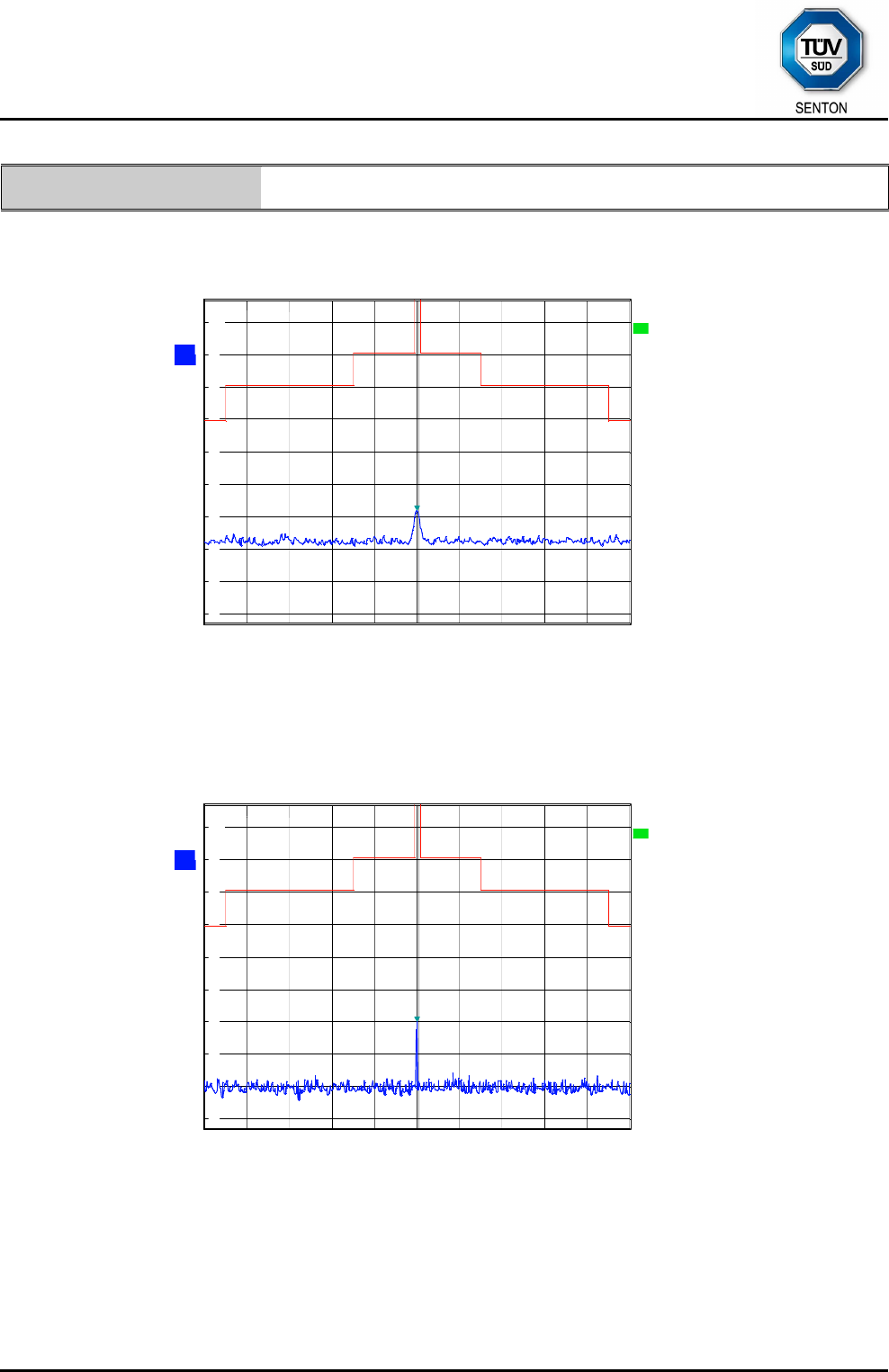
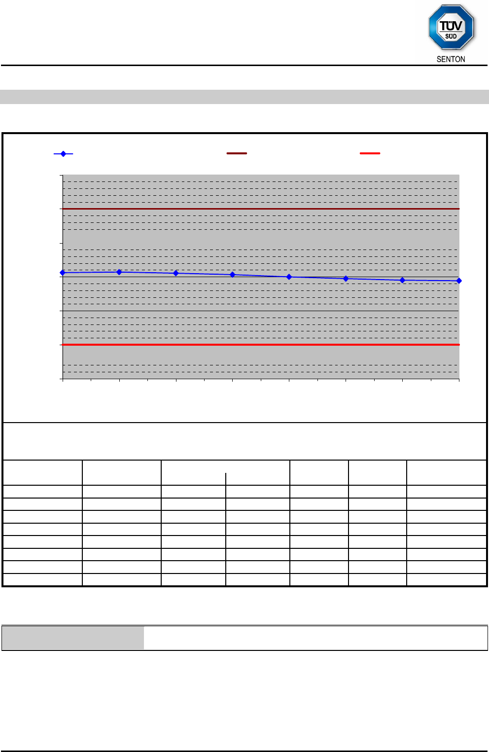
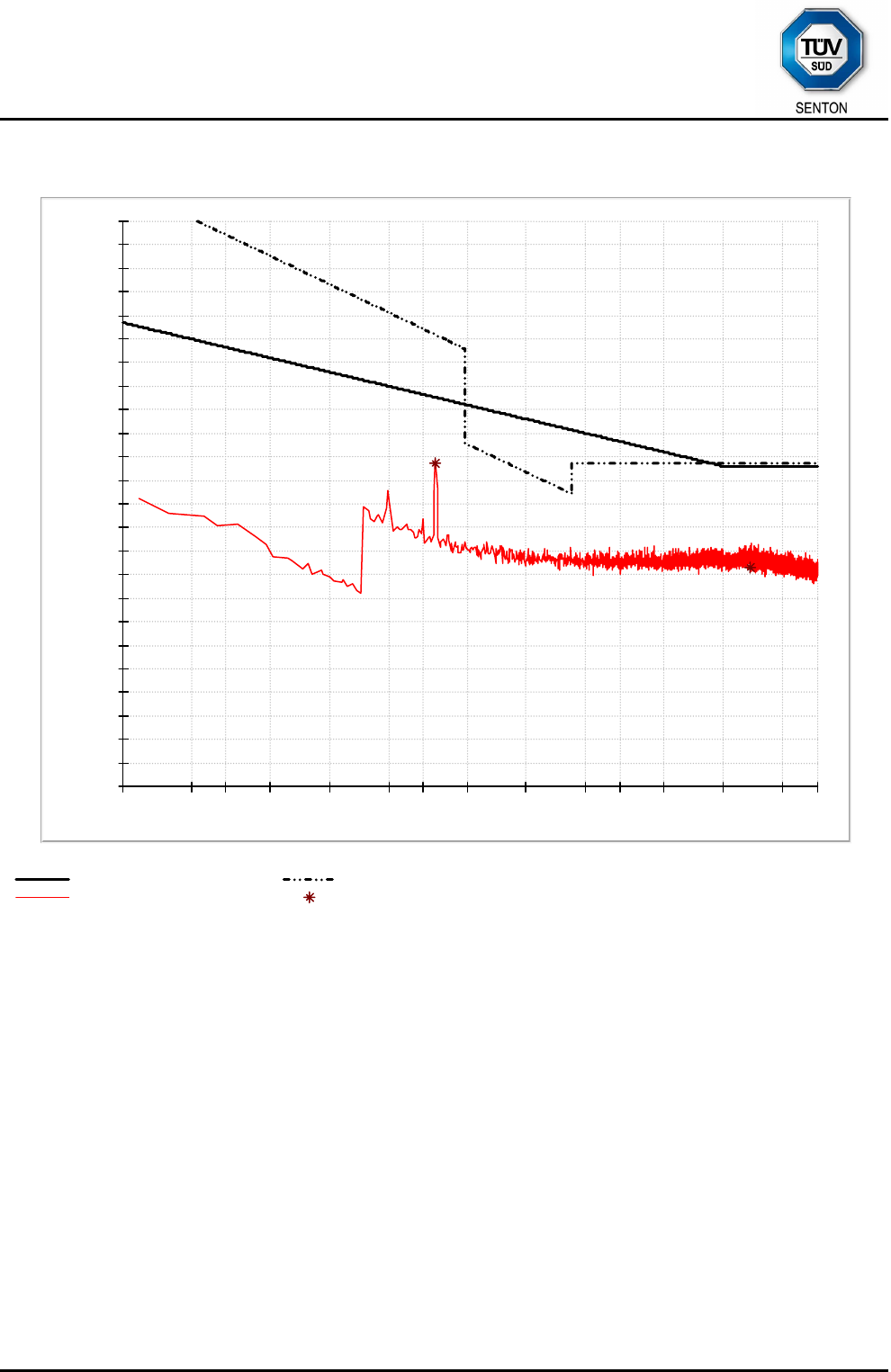
-20
-10
0
10
20
30
40
50
60
70
80
90
100
9k 20 30 50 100k 200 300 500 1M 2M 3M 5M 10M 20 30M
Level in dBµV/m
Frequency in Hz
EN 300 330 tx mag FCC 15.209 mag (10 m)
MaxPeak-ClearWrite-PK+ Final Result 1-QPK
TÜV SÜD SENTON GmbH
Äußere Frühlingstraße 45
94315 Straubing
Germany
Phone: +49 9421 5522-0
Fax: +49 9421 5522-99
Web: www.tuev-sued.de/senton
eMail: senton@tuev-sued.de
Test Report No. 14912-03335-1 (Edition 1) Page 57 of 59 Pages
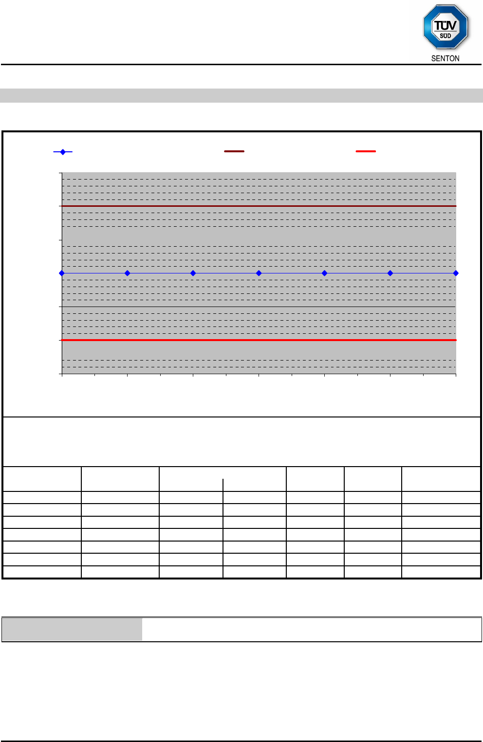
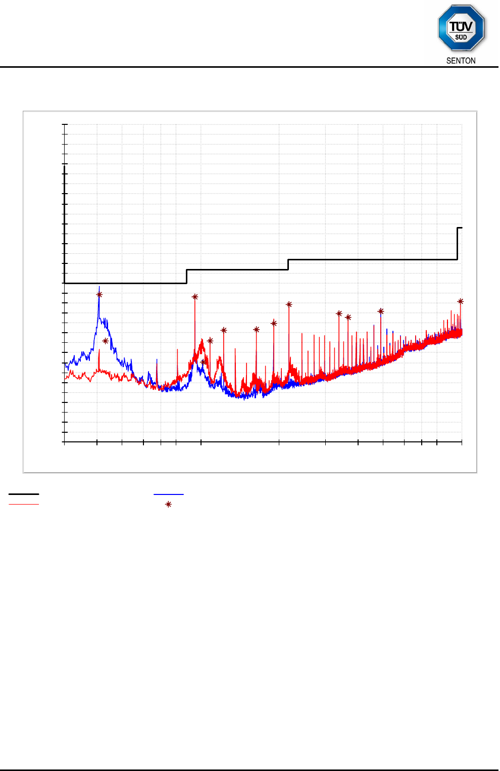
0
5
10
15
20
25
30
35
40
45
50
55
60
65
70
75
80
30M 50 60 80 100M 200 300 400 500 800 1G
Level in dBµV/m
Frequency in Hz
FCC 15.209 MaxPeak-MaxHold-PK+
MaxPeak-MaxHold-PK+ Final Result 1-QPK

TÜV SÜD SENTON GmbH
Äußere Frühlingstraße 45
94315 Straubing
Germany
Phone: +49 9421 5522-0
Fax: +49 9421 5522-99
Web: www.tuev-sued.de/senton
eMail: senton@tuev-sued.de
Test Report No. 14912-03335-1 (Edition 1) Page 58 of 59 Pages
12 Calibration Data
Test Equipment List with Calibration Data
Test report number(s):14912-03335-1 Date of test:
December 2010 / January 2011
Date of Calibration
Type Inv.-No. Type Designation Serial Number Manufacturer Calibration Organization
Last Next
EMI test receiver 1028 ESHS10 860043/016 Rohde & Schwarz Rohde & Schwarz 10/2010 04/2012
EMI test receiver 1711 ESPI7 836914/0002 Rohde & Schwarz Rohde & Schwarz 09/2009 03/2011
EMI test receiver 2044 ESU8 100232 Rohde & Schwarz Rohde & Schwarz 12/2010 06/2012
Spectrum analyser 1666 FSP30 100063 Rohde & Schwarz Rohde & Schwarz 11/2009 05/2011
V-network 1059 ESH3-Z5 894785/005 Rohde & Schwarz Rohde & Schwarz 11/2010 11/2012
Loop antenna 1016 HFH2-Z2 882964/0001 Rohde & Schwarz Rohde & Schwarz 09/2009 03/2011
TRILOG Broadband Antenna 1802 VULB 9163 9163-214 Schwarzbeck Schwarzbeck 11/2009 05/2011
Multimeter 1653 21 III 76530546 Fluke ZMK 11/2010 11/2012
Note: Date of next calibration contains maximum tolerance if applicable.
Page 59 of 59