Siemens RF310R Tag Reader User Manual SIMATIC Sensors RFID systems SIMATIC RF300
Siemens AG Tag Reader SIMATIC Sensors RFID systems SIMATIC RF300
Siemens >
Contents
- 1. User Manual I
- 2. User Manual II
- 3. User Manual III
- 4. User Manual IV
User Manual I
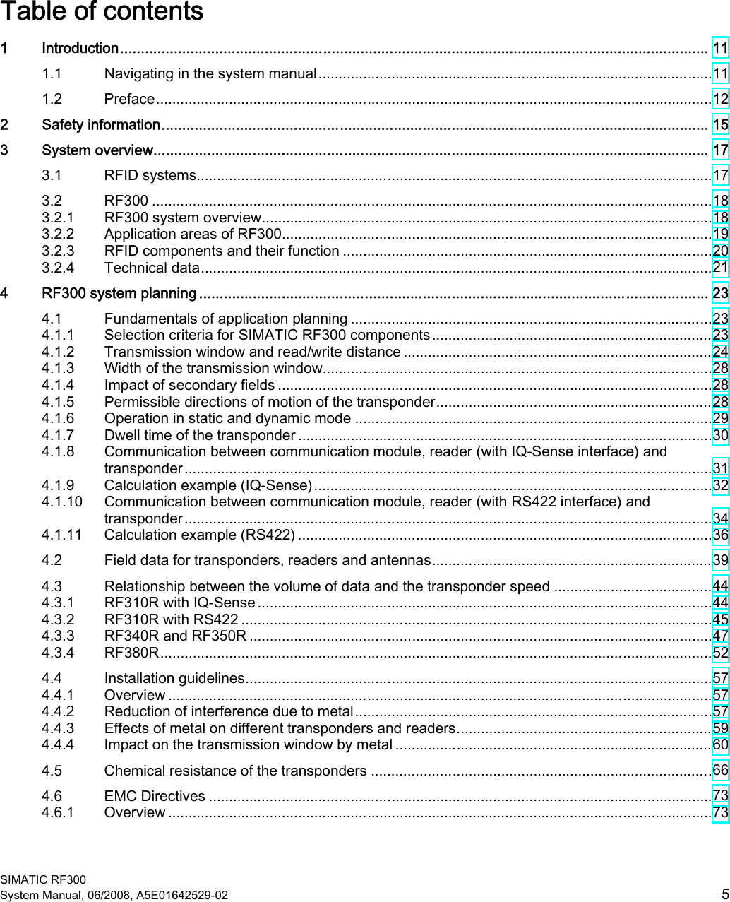
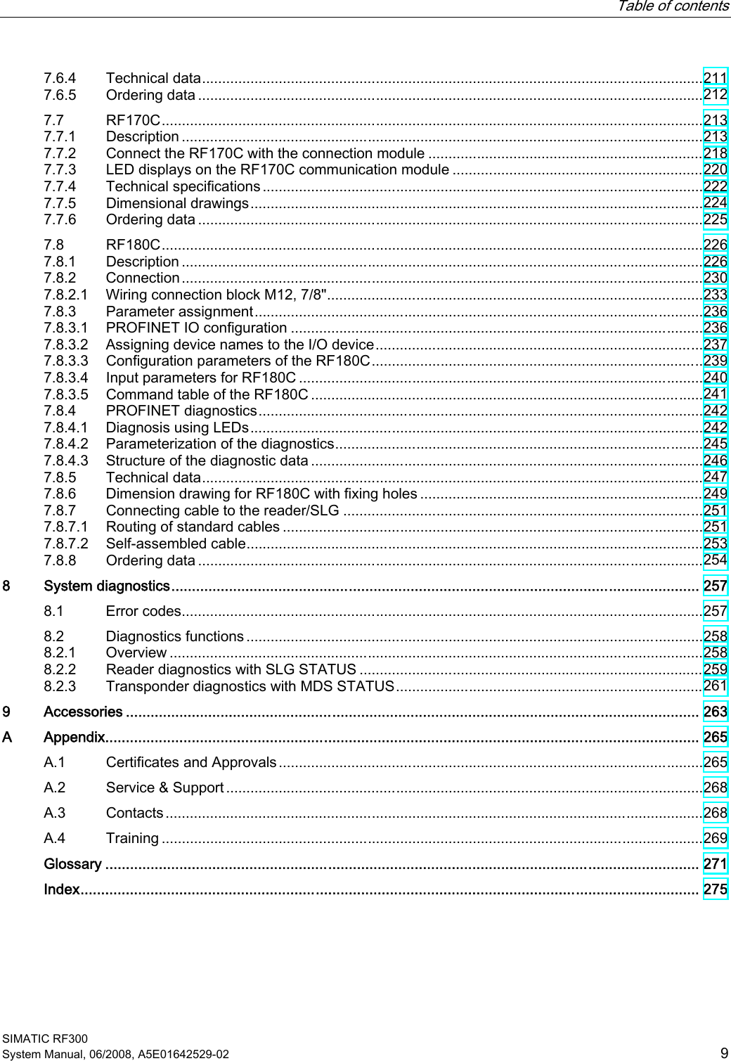


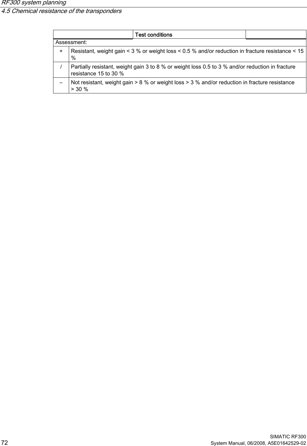
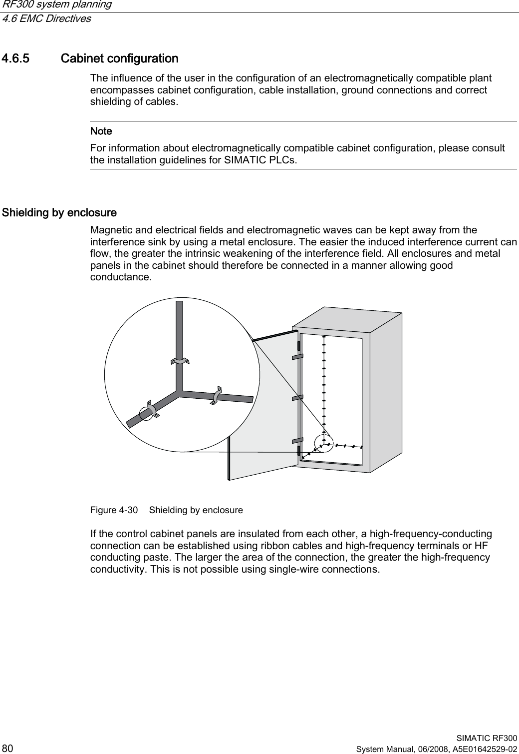
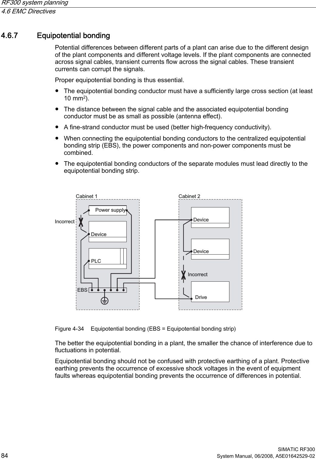
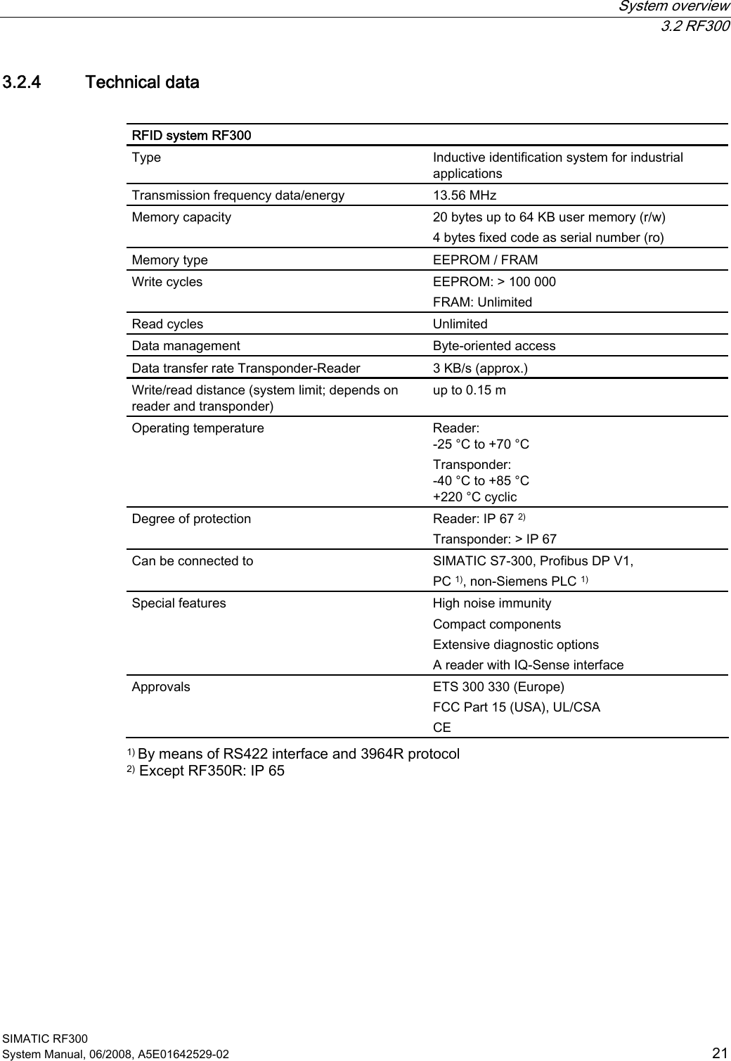
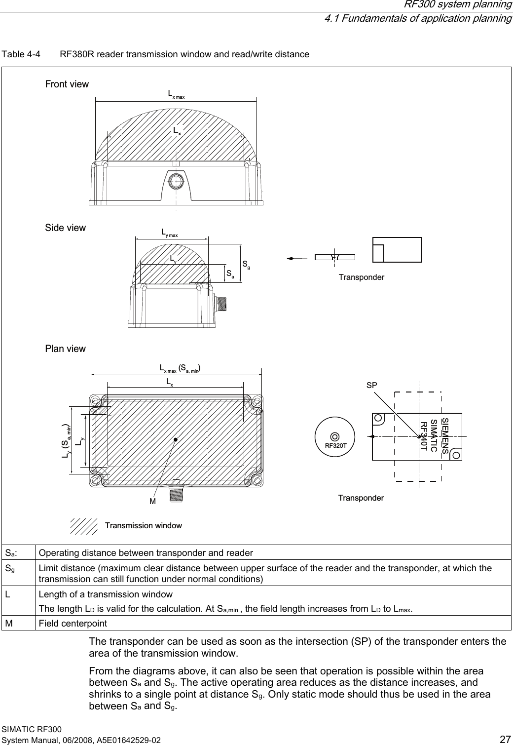
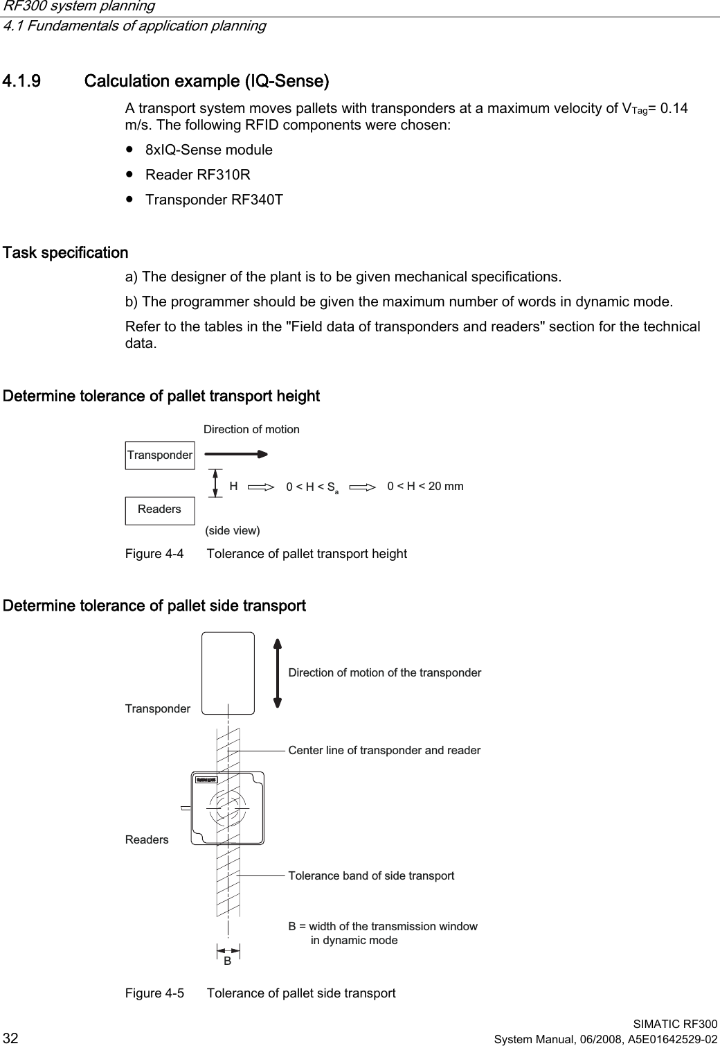
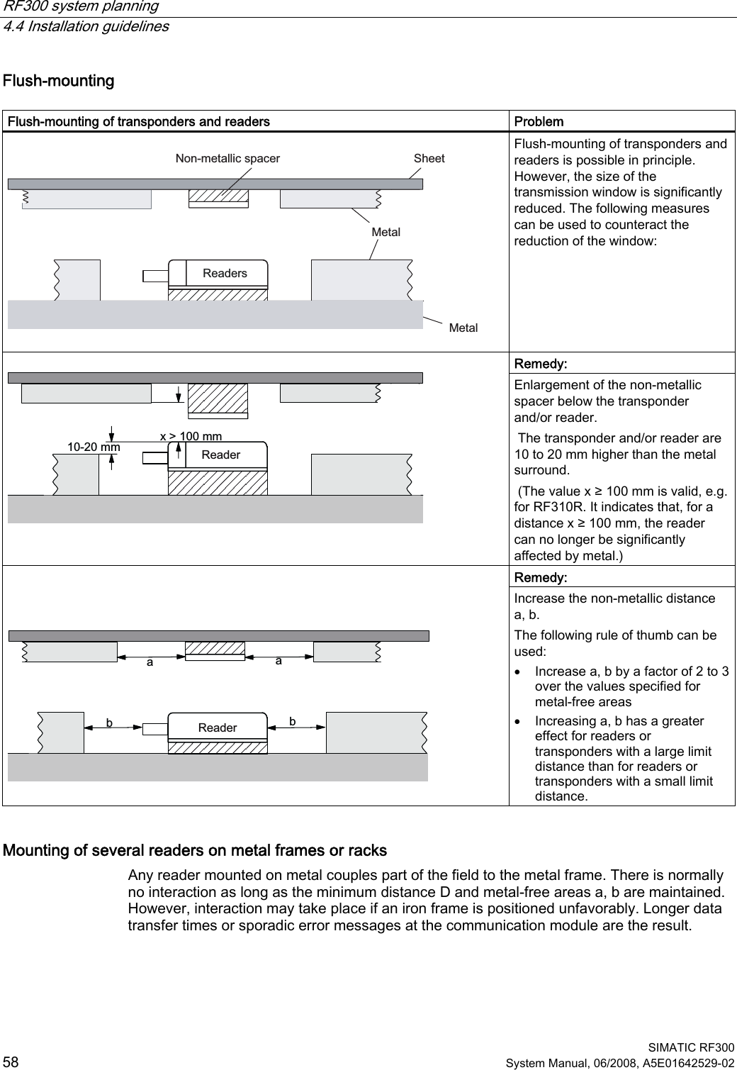
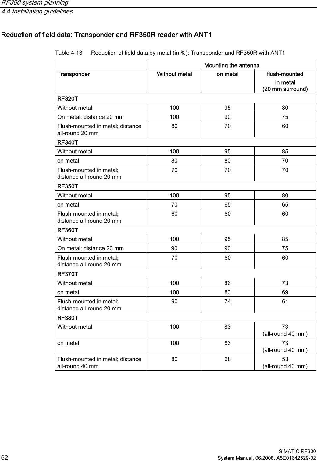
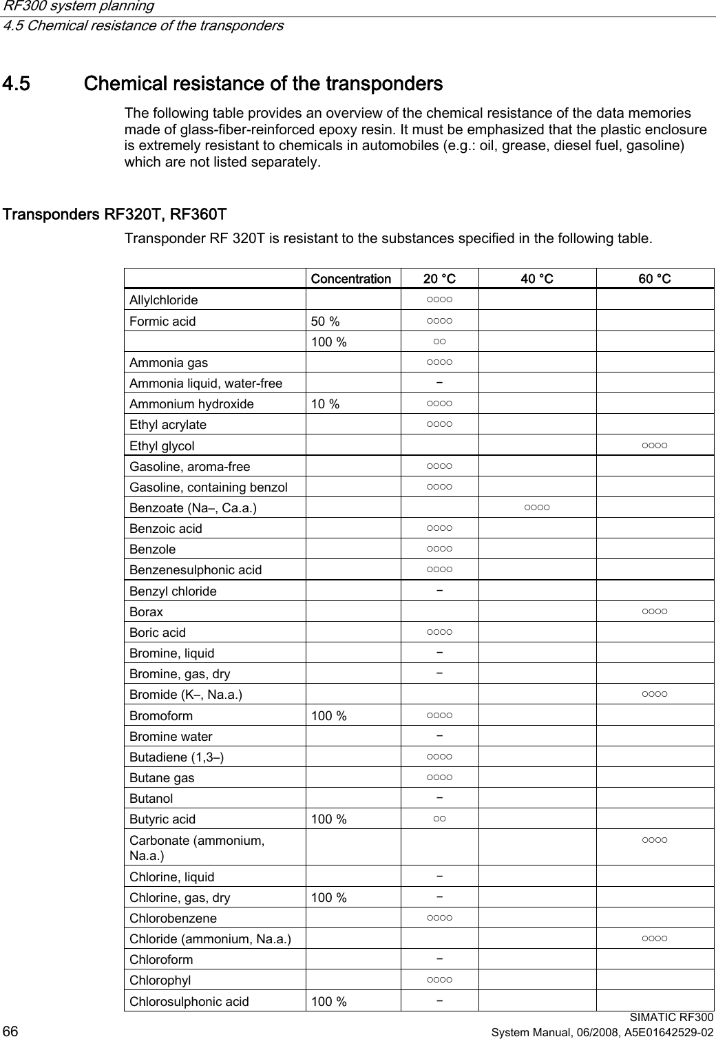
![System overview 3.2 RF300 SIMATIC RF300 20 System Manual, 06/2008, A5E01642529-02 3.2.3 RFID components and their function RF300 system components 6HULDODV\QFKURQRXVLQWHUIDFH565)7 5)73RZHUDQGGDWDWUDQVPLVVLRQ0+]5)5,46HQVH[,46HQVHIRU(70RQ6ZLWK)&3&LQWHUIDFHWKLUGSDUW\3/&$60IRU6,0$7,&65)&IRU(7SUR$60IRU(7;DQG)&$60IRU352),%86'395)7 5)7 5)7 5)75)5 5)5 5)5$60bIRU352),%86'3'39,46HQVHLQWHUIDFH5)556565)&IRU352),1(7,2 Communication modules A communication module (interface module) is used to integrate the RF identification system in PLC/automation systems. Readers The reader (read/write device) ensures inductive communication, supplies power to the transponder, and handles the connection to the various PLCs (e.g. SIMATIC S7) through the communication module (e.g. ASM 475). Transponder The transponder (data memory) stores all data relevant to the production process and is used, for example, instead of barcode. Conventions The RF310R, RF340R and RF380R readers are equipped with an integral antenna, whereas the RF350R reader is operated over an external antenna. In this system manual, the term "Reader" is used throughout even where it is actually referring to the antenna of the reader.](https://usermanual.wiki/Siemens/RF310R.User-Manual-I/User-Guide-986213-Page-20.png)


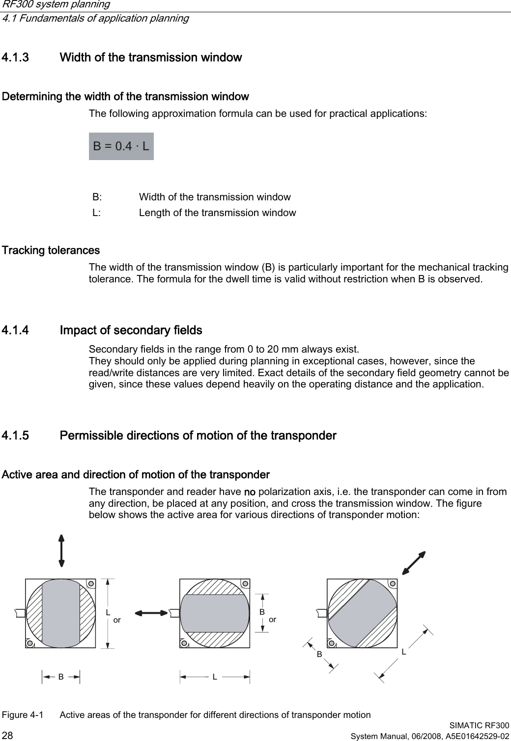
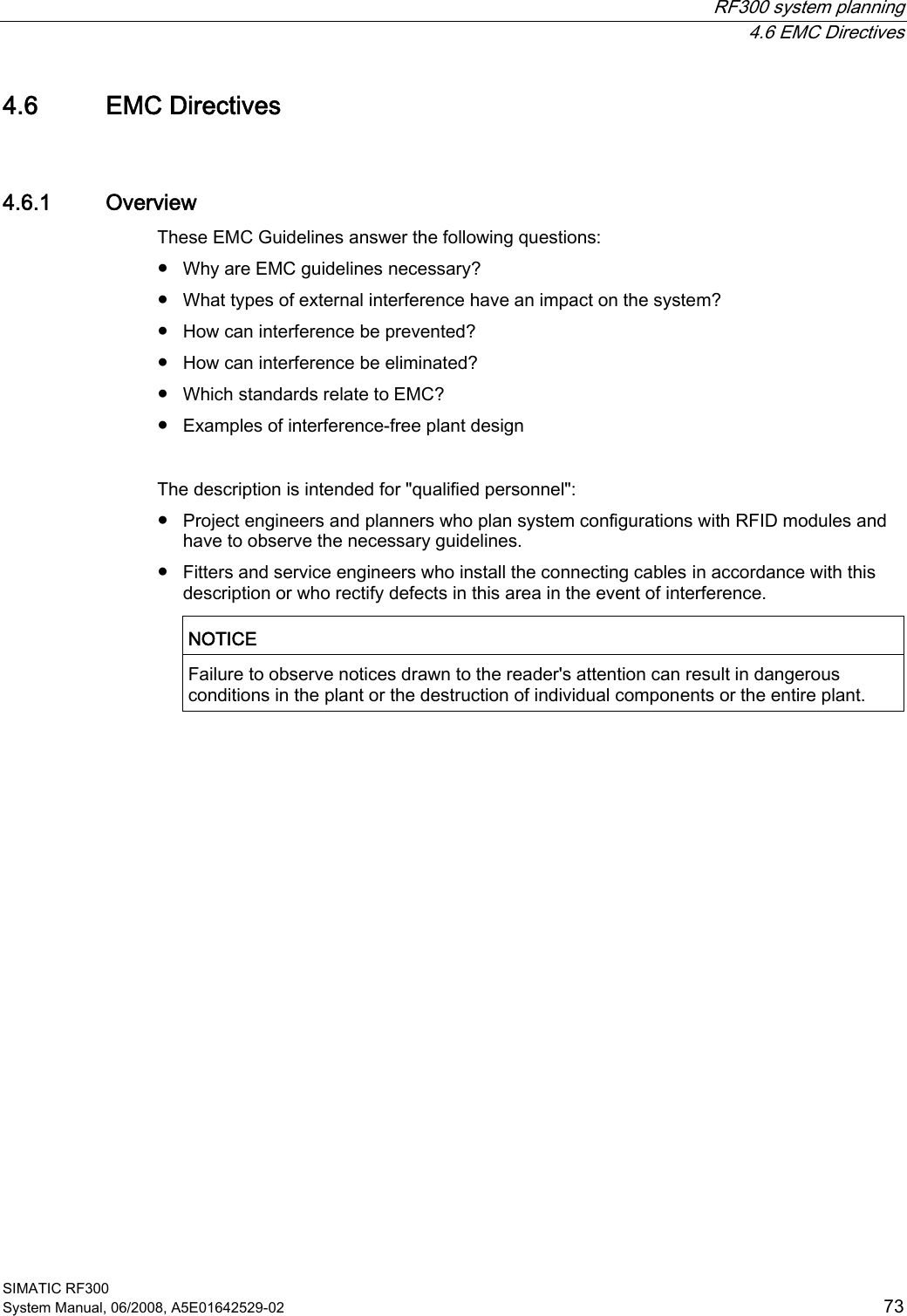
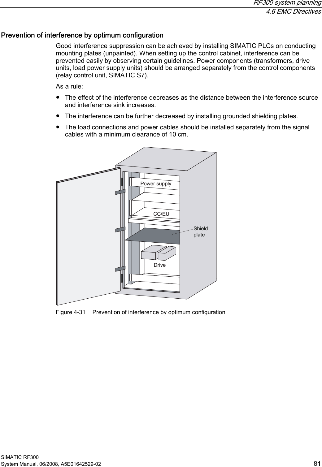
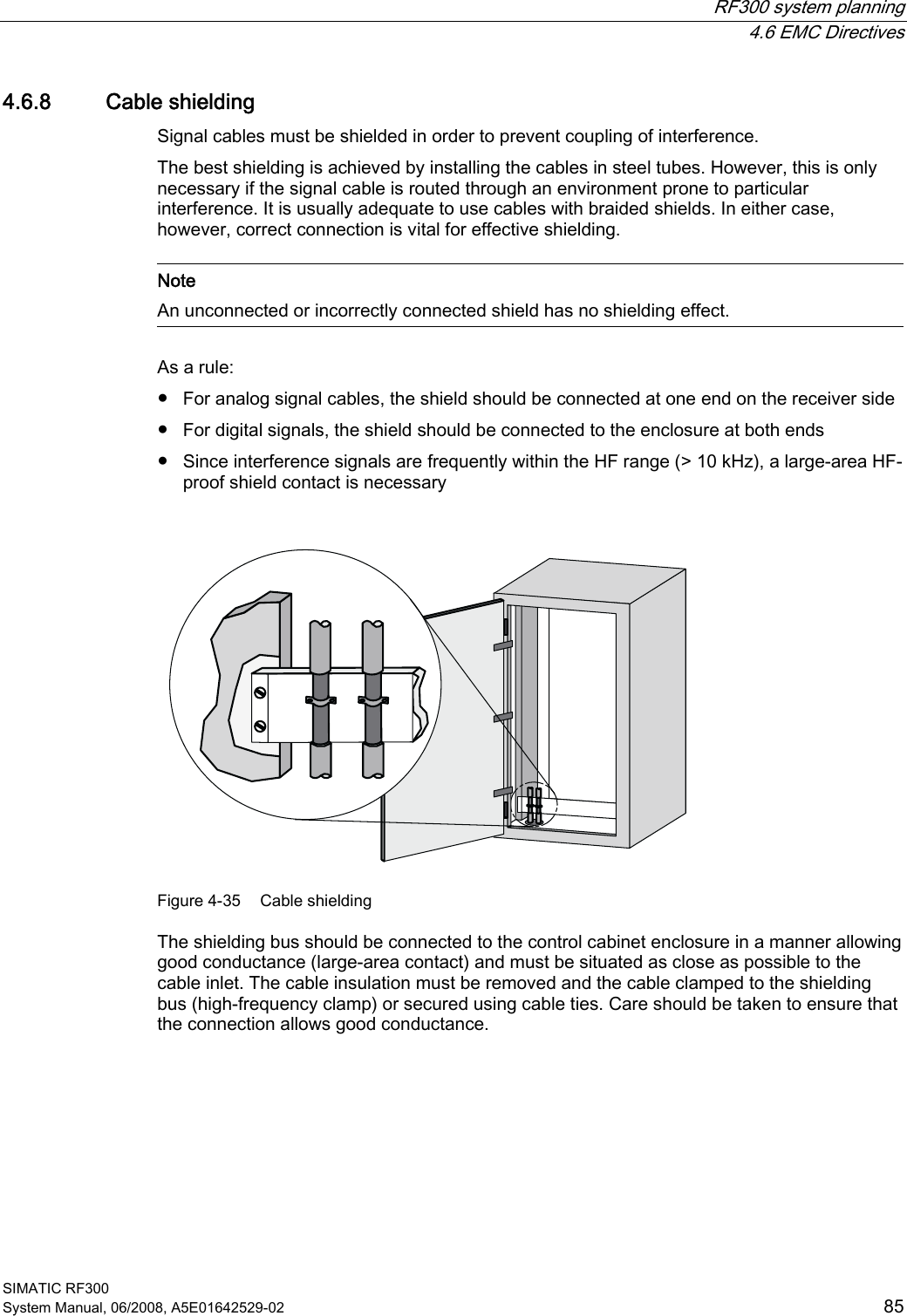
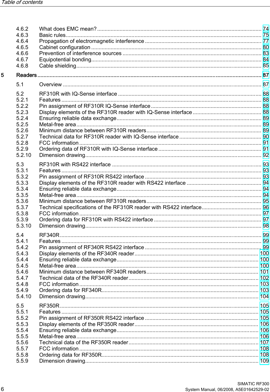
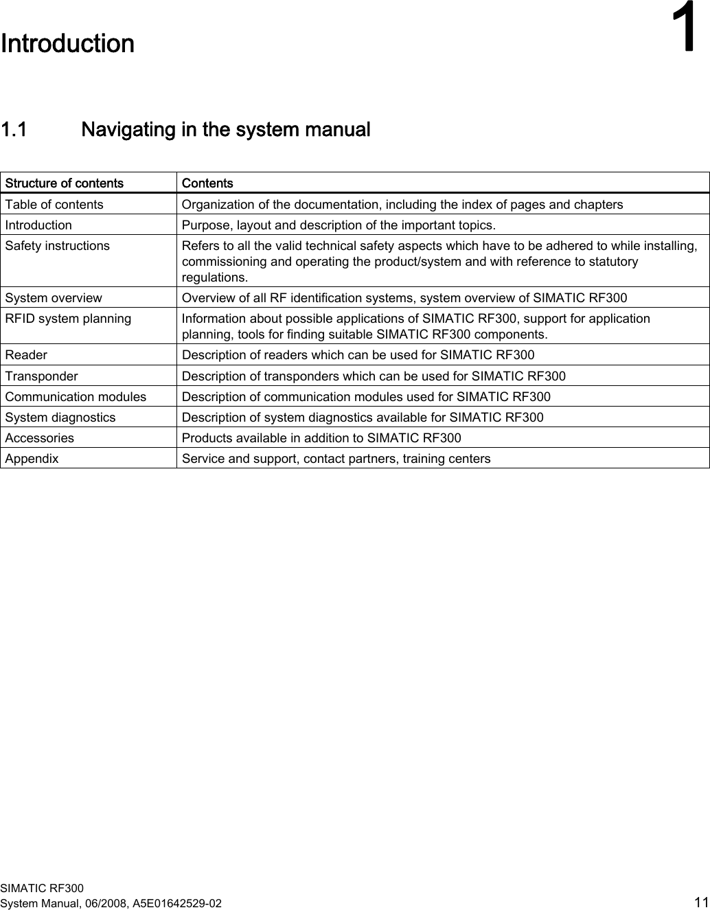
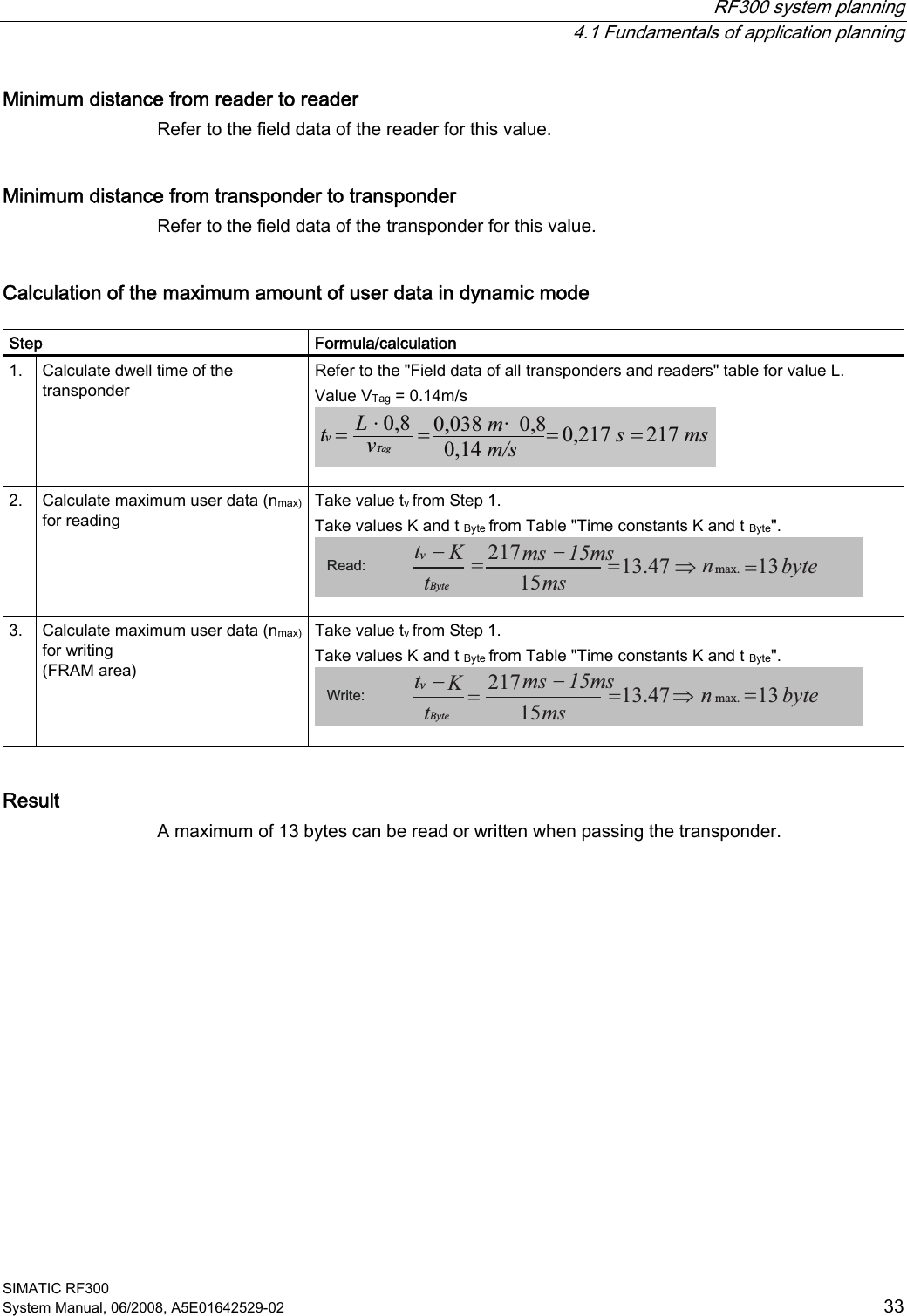
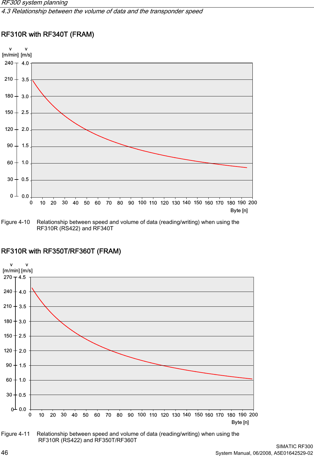
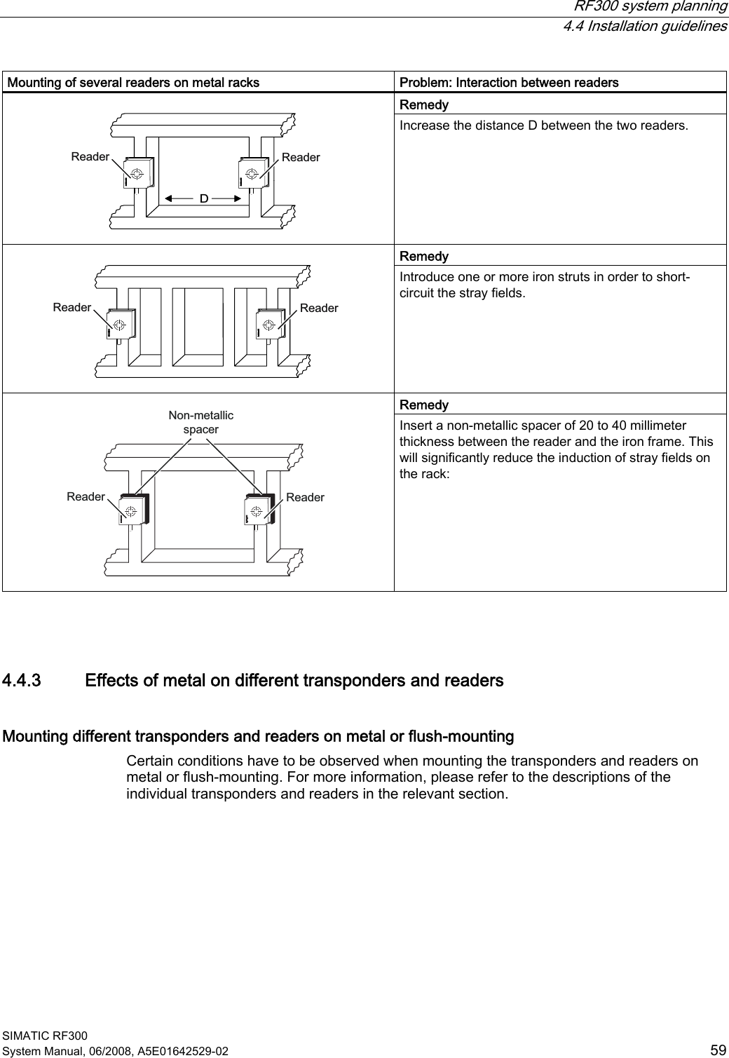
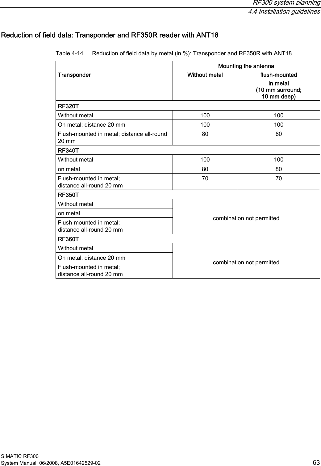
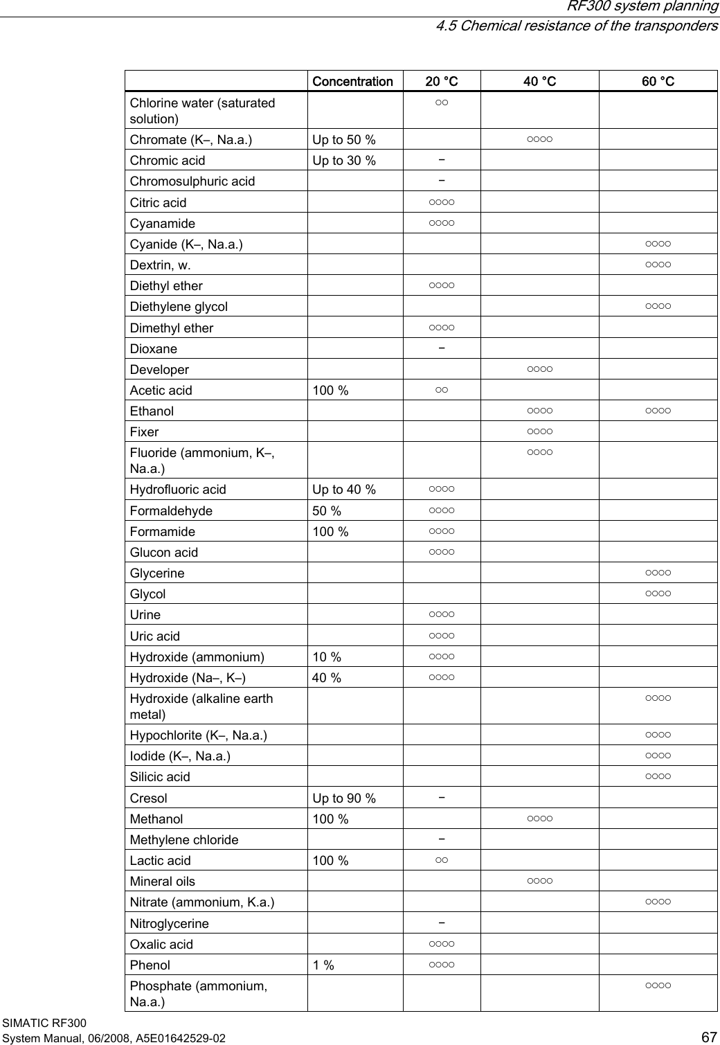
![RF300 system planning 4.1 Fundamentals of application planning SIMATIC RF300 30 System Manual, 06/2008, A5E01642529-02 4.1.7 Dwell time of the transponder The dwell time is the time in which the transponder remains within the transmission window of a reader. The reader can exchange data with the transponder during this time. The dwell time is calculated thus: 0,8 [ ][/]TagvL mtv m s⋅= tV: Dwell time of the transponder L: Length of the transmission window vTag: Speed of the transponder (tag) in dynamic mode 0,8: Constant factor used to compensate for temperature impacts and production tolerances The dwell time can be of any duration in static mode. The dwell time must be sufficiently long to allow communication with the transponder. The dwell time is defined by the system environment in dynamic mode. The volume of data to be transferred must be matched to the dwell time or vice versa. In general: Kvtt≥ tV:: Dwell time of the data memory within the field of the reader tK: Communication time between transponder and communication module](https://usermanual.wiki/Siemens/RF310R.User-Manual-I/User-Guide-986213-Page-30.png)
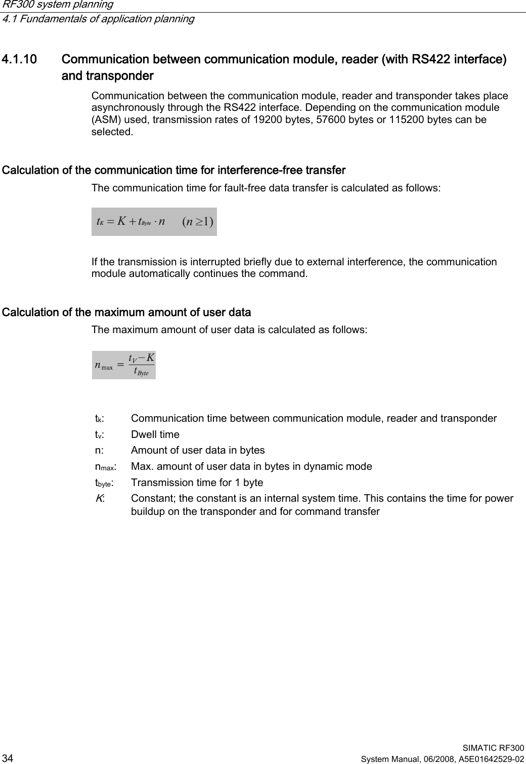
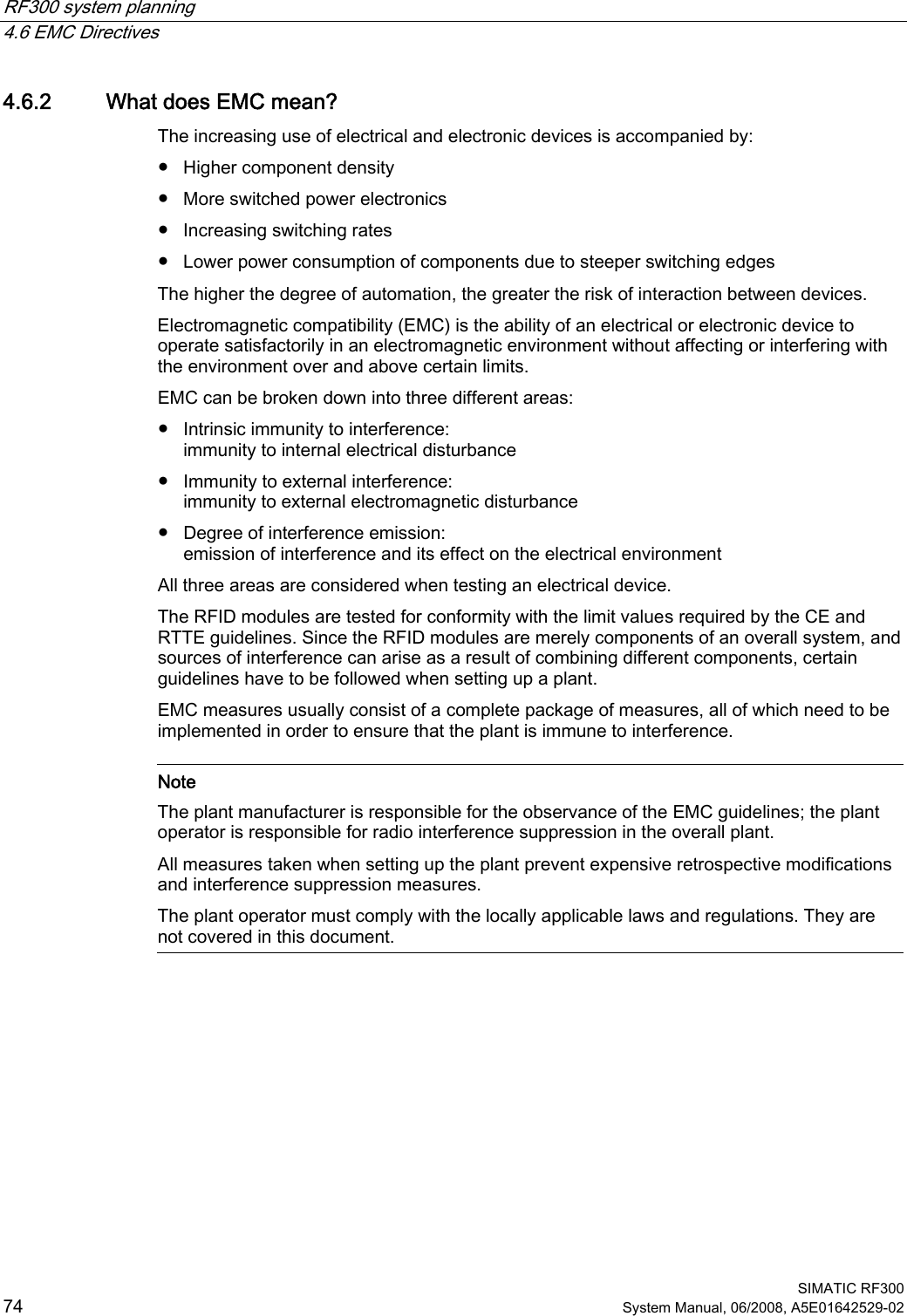
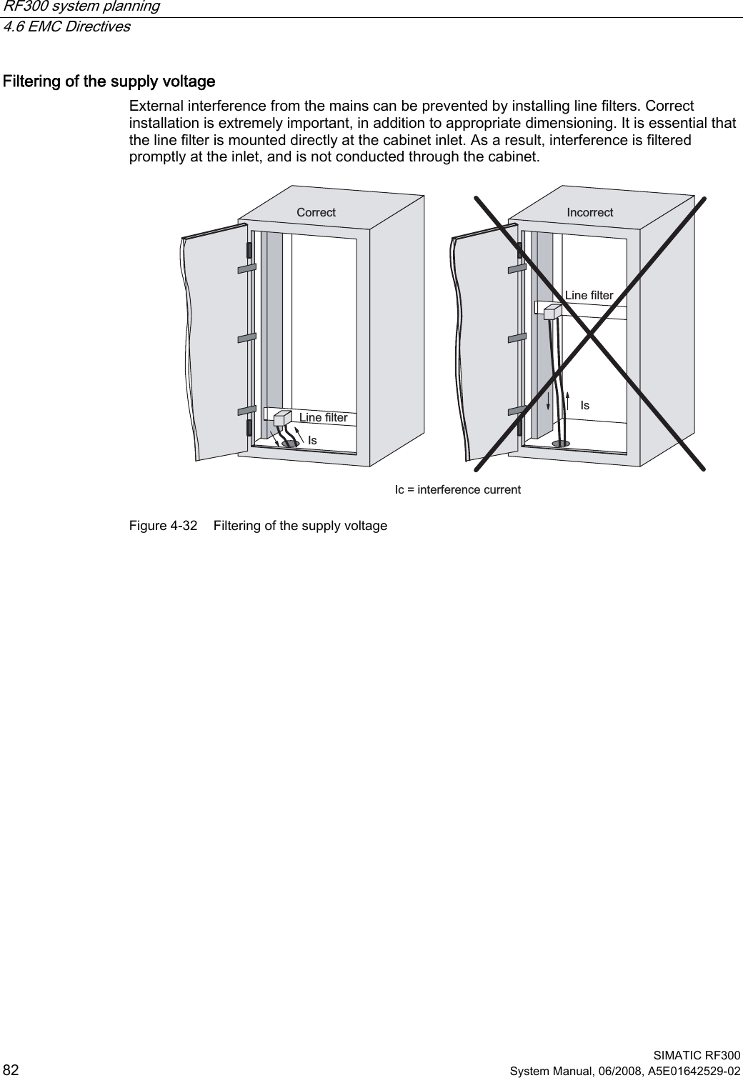
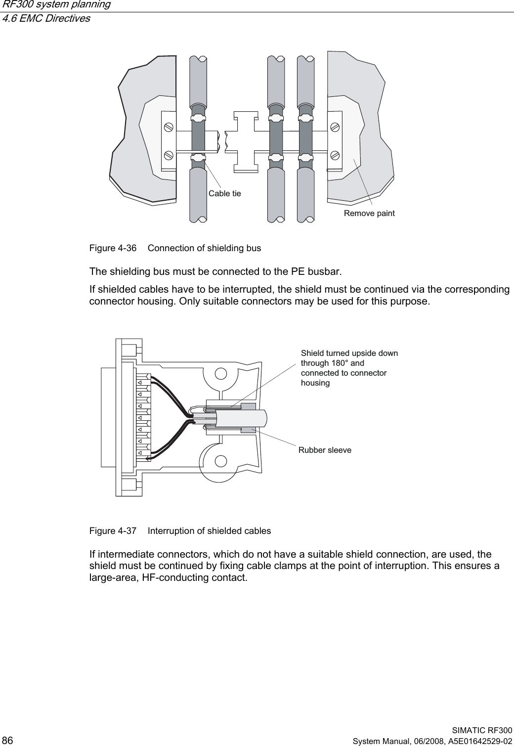
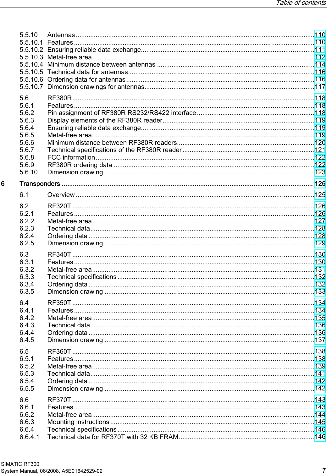
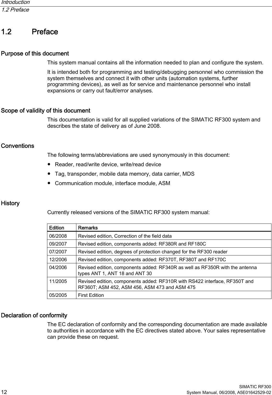
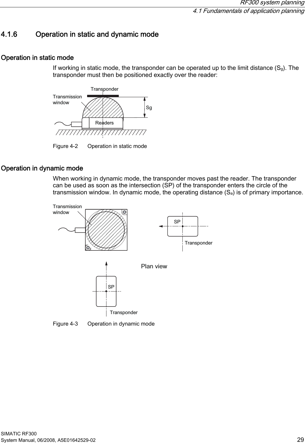
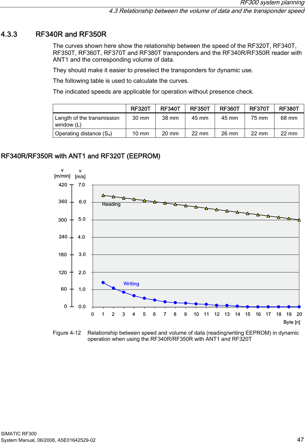
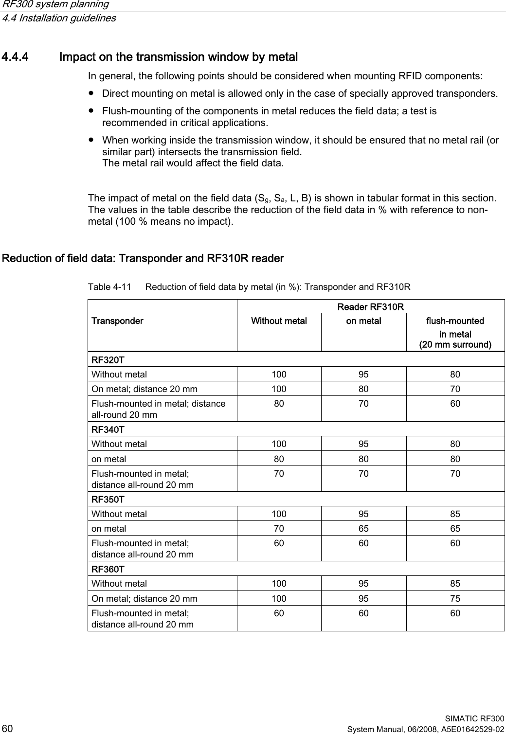
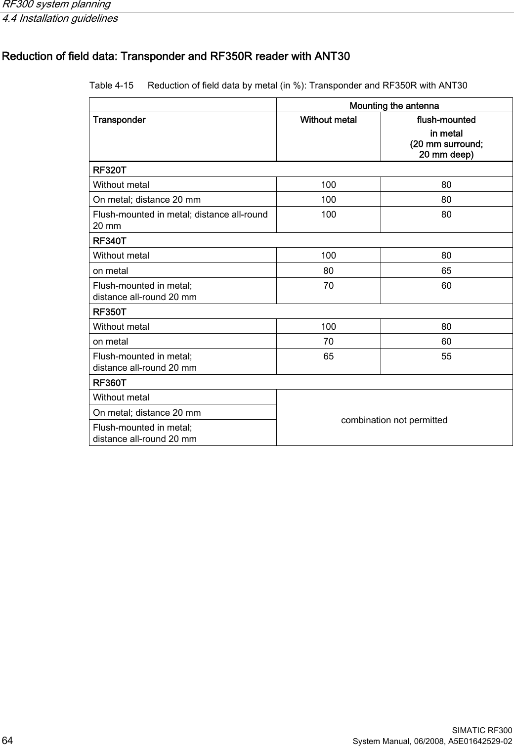
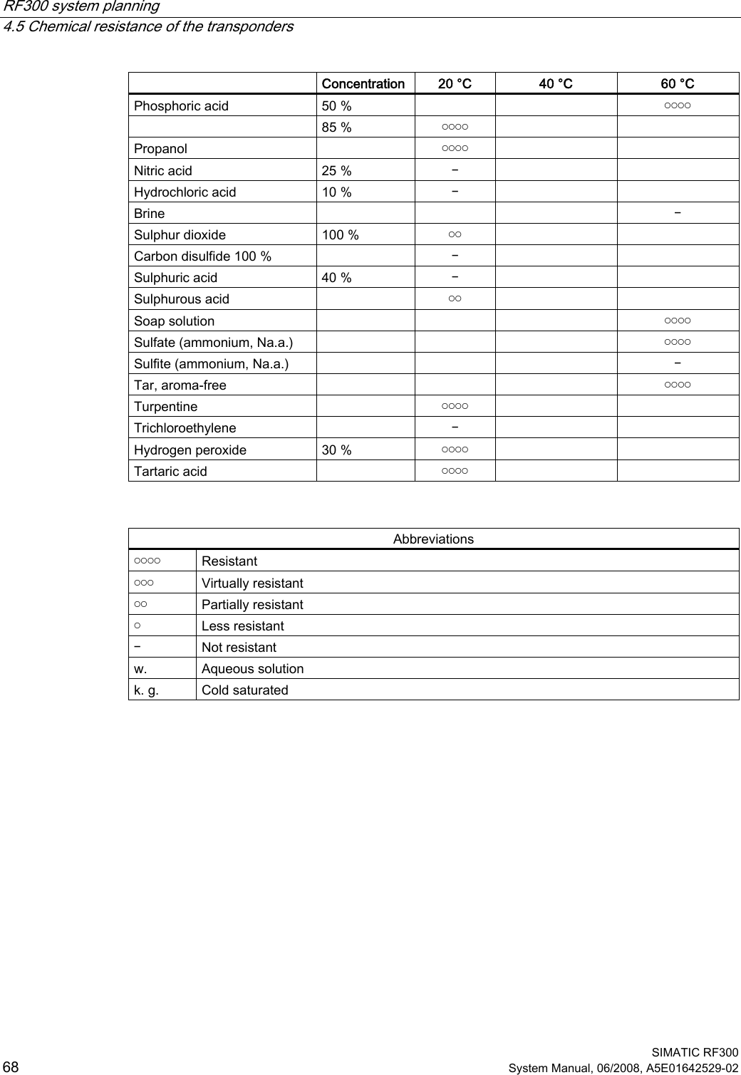
![RF300 system planning 4.1 Fundamentals of application planning SIMATIC RF300 System Manual, 06/2008, A5E01642529-02 35 Time constants K and tbyte Transmission rate [baud] K [ms] tbyte [ms] 19200 28 0,85 57600 14 0,38 115200 11 0,28 The values for K and tbyte include the overall time that is required for communication in static mode. It is built up from several different times: • Serial communication between communication module, reader and • Processing time between reader and transponder and their internal processing time. The values shown in the table must be used when calculating the maximum quantity of user data in static mode. They are applicable for both reading and writing in the FRAM area. For writing in the EEPROM area (max. 20 bytes), the byte time tByte is approx. 11 ms. Transmission rate [baud] Memory area K [ms] tbyte [ms] Independent FRAM 8,5 0,13 Independent Write Read EEPROM 8,5 8,5 12,2 0,13 In dynamic mode, the values for K and tbyte are independent of the transmission speed. The communication time only includes the processing time between the reader and the transponder and the internal system processing time of these components. The communication times between the communication module and the reader do not have to be taken into account because the command for reading or writing is already active when the transponder enters the transmission field of the reader. The values shown above must be used when calculating the maximum quantity of user data in dynamic mode. They are applicable for both writing and reading.](https://usermanual.wiki/Siemens/RF310R.User-Manual-I/User-Guide-986213-Page-35.png)
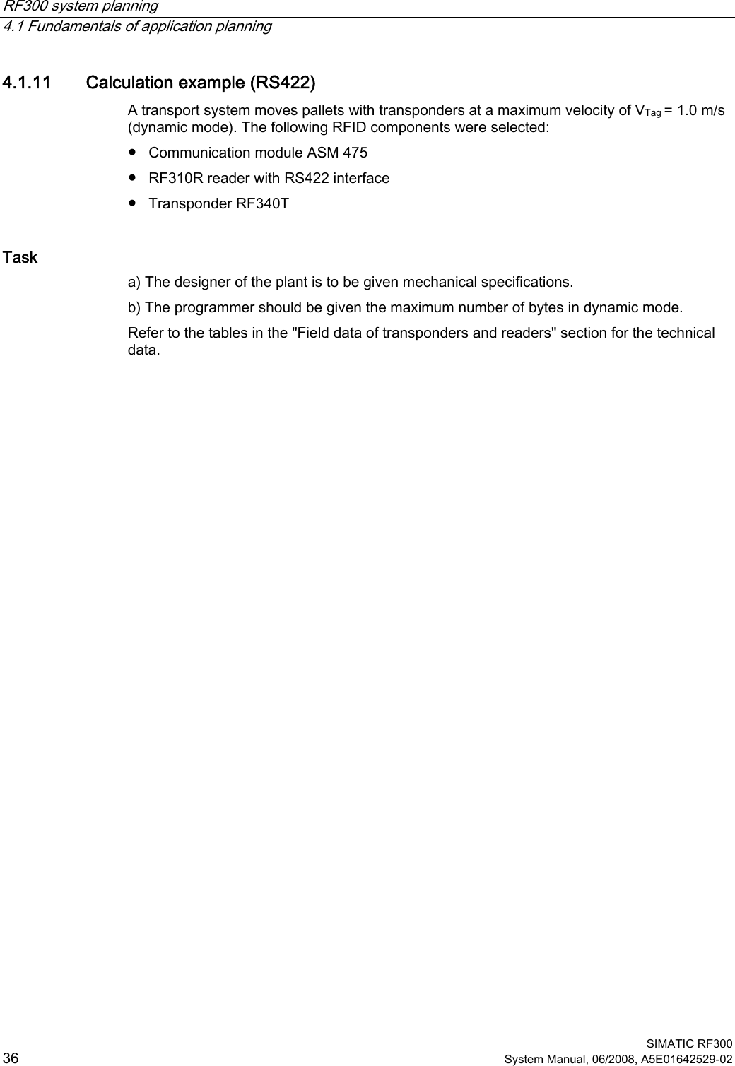

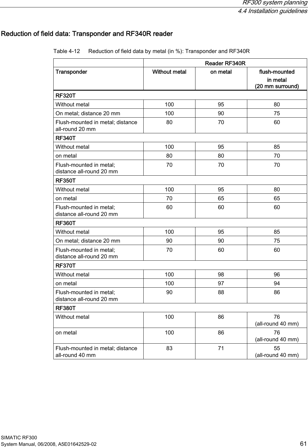
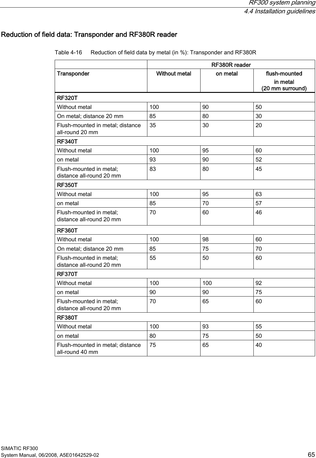
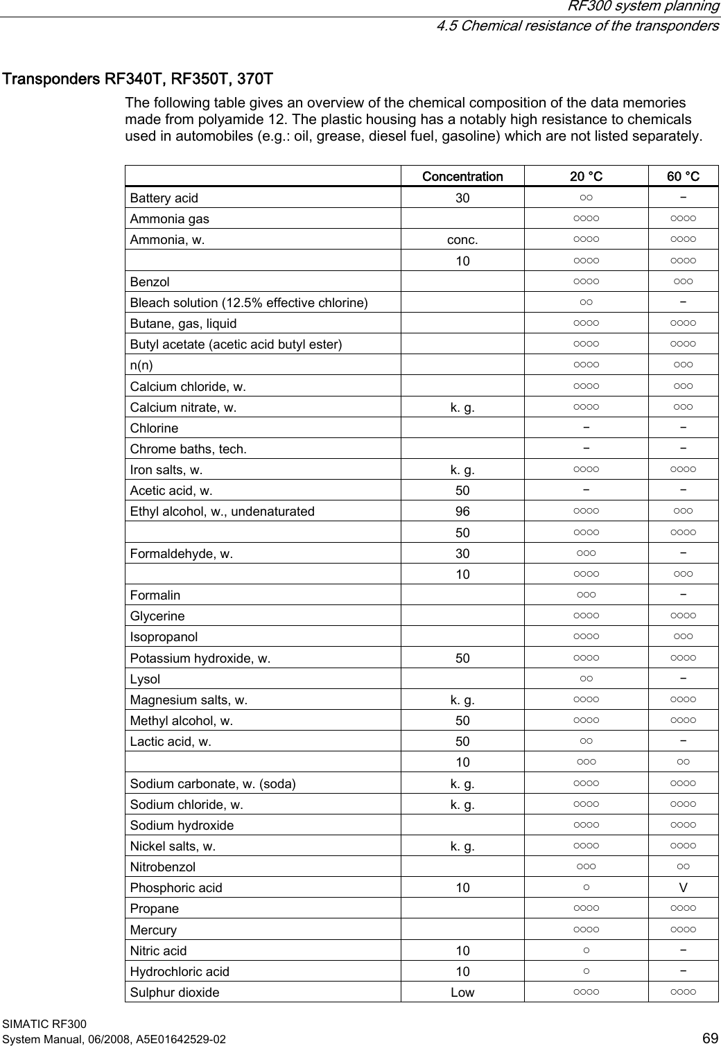
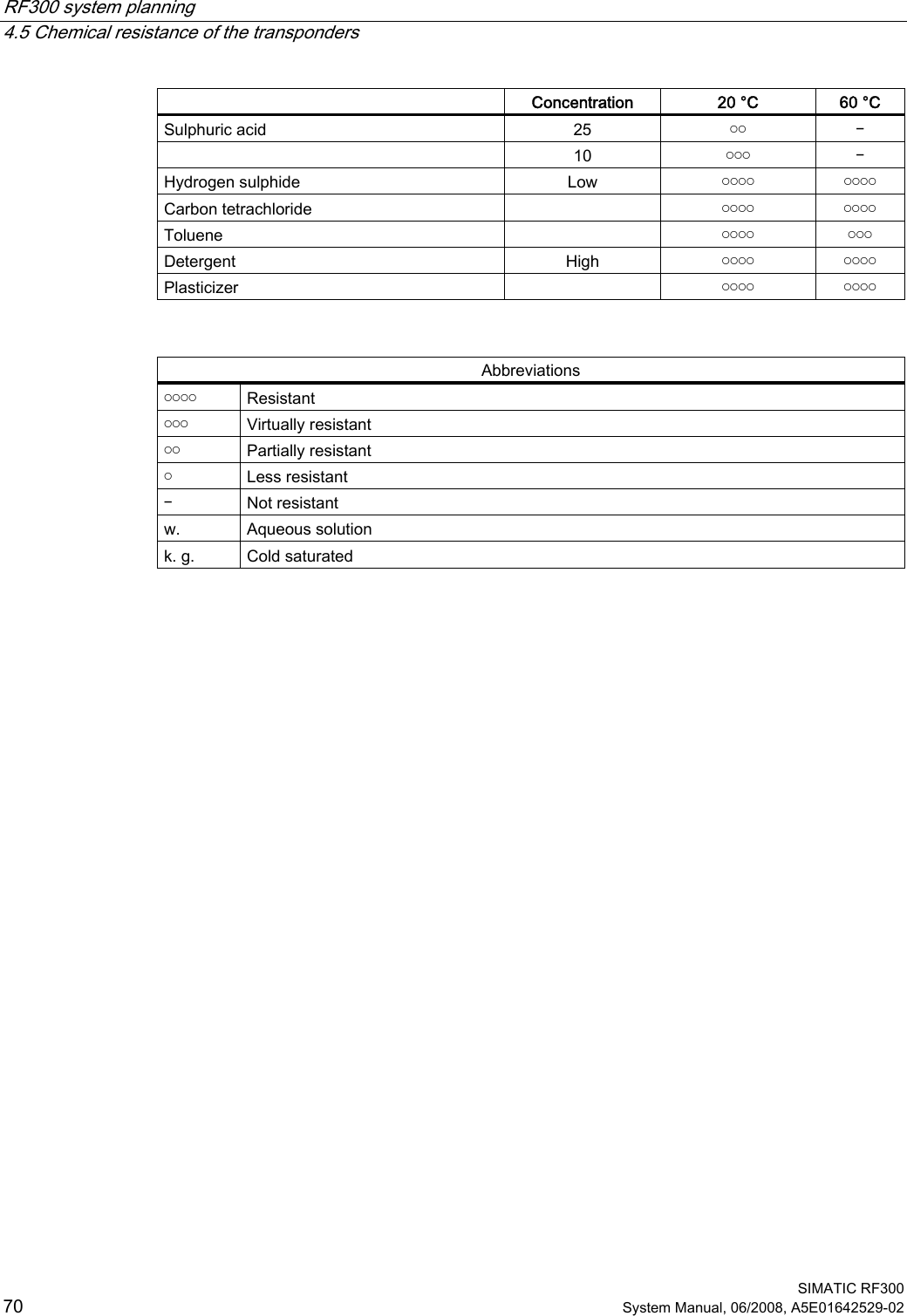
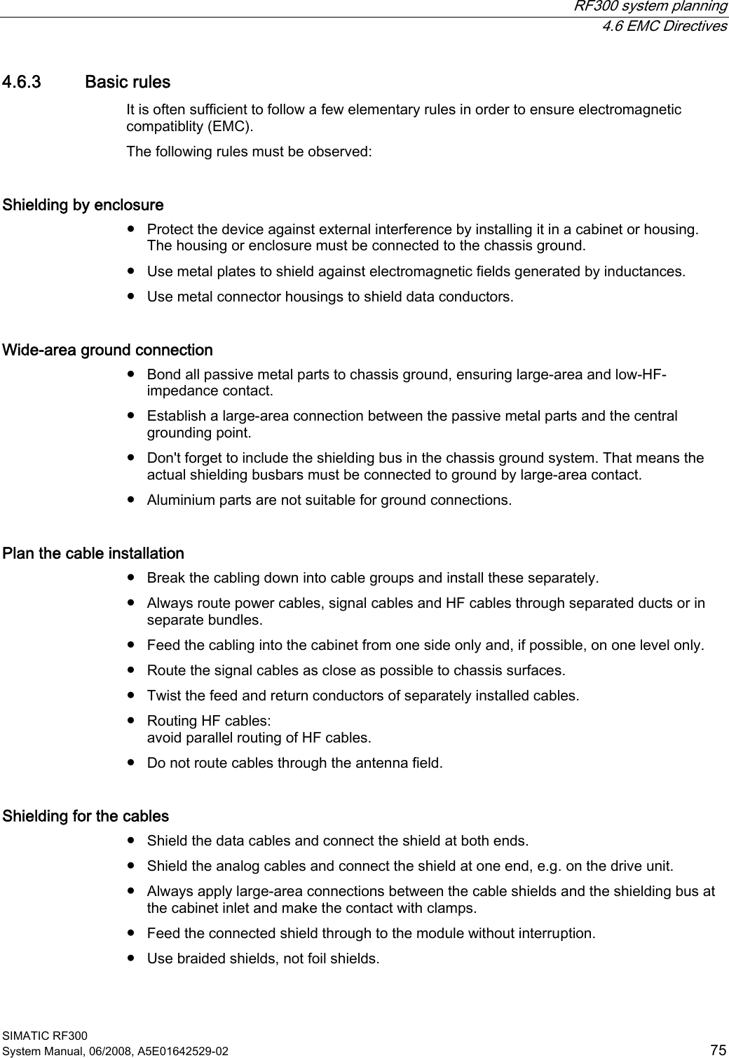
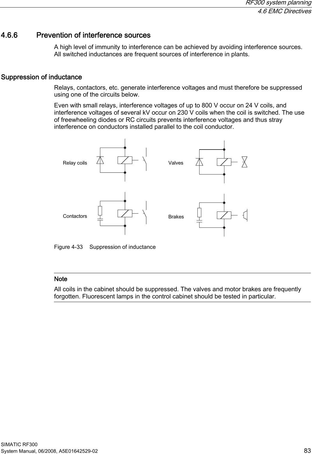
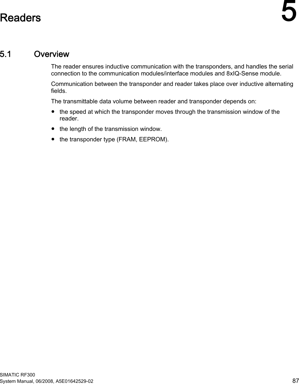
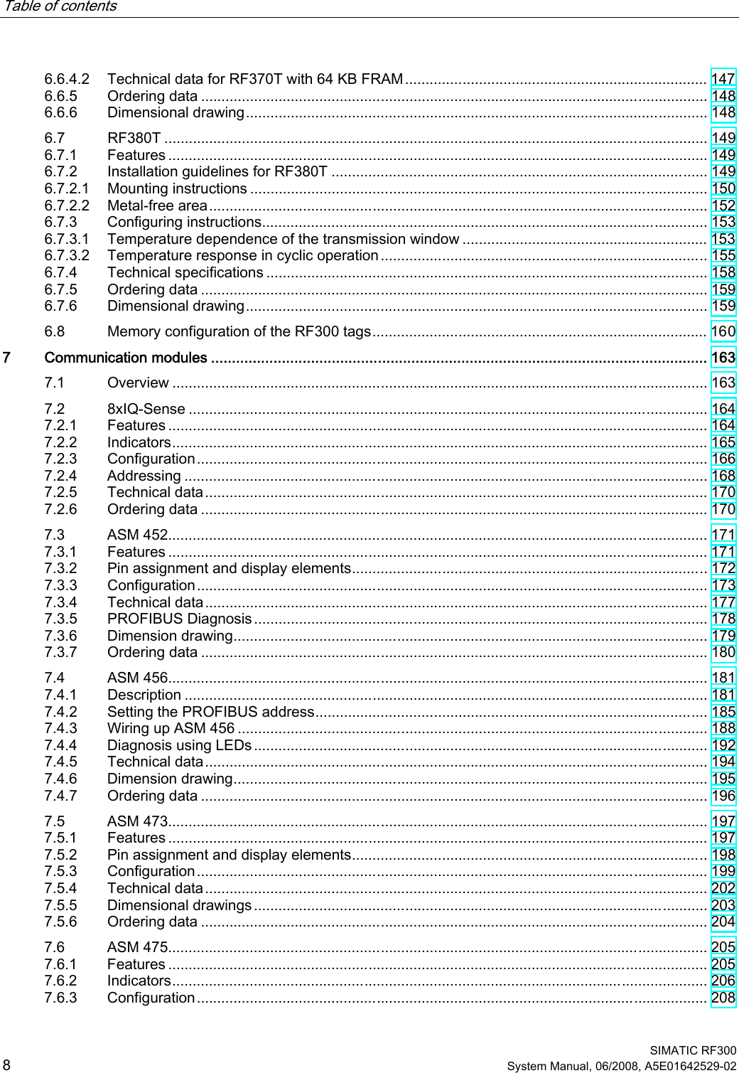
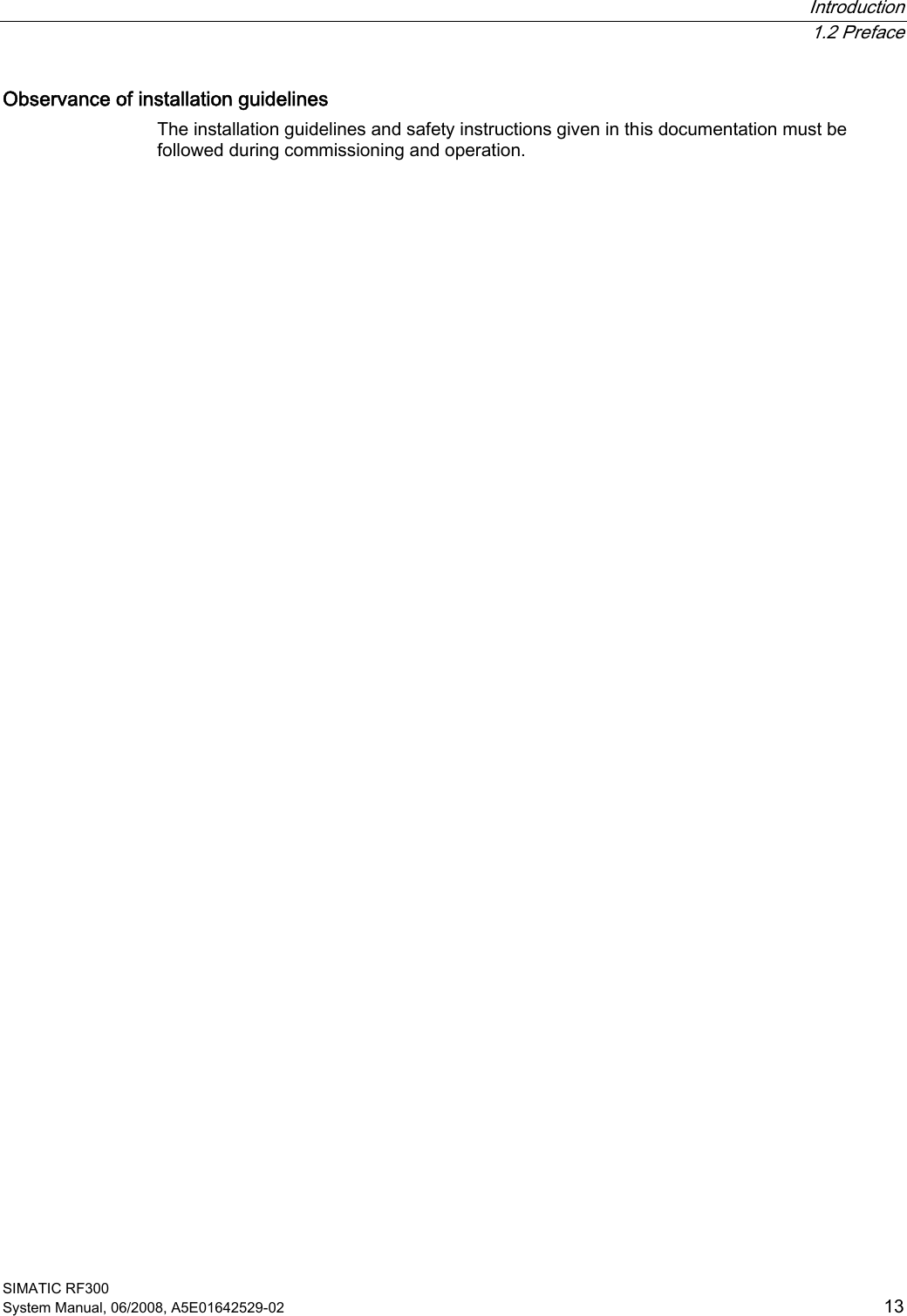
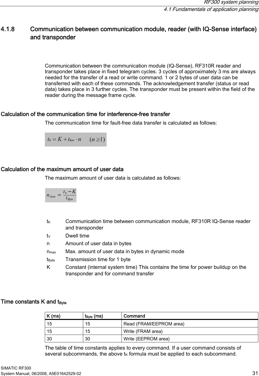
![RF300 system planning 4.5 Chemical resistance of the transponders SIMATIC RF300 System Manual, 06/2008, A5E01642529-02 71 Transponder RF380T The housing of the heat-resistant data storage unit is made of polyphenylene sulfide (PPS). The chemical resistance of the data storage unit is excellent. No solvent is known that can dissolve the plastic at temperatures below 200 °C. A reduction in the mechanical properties has been observed in aqueous solutions of hydrochloric acid (HCl) and nitric acid (HNO3) at 80 °C. The excellent resistance to all fuel types including methanol is a particular characteristic. The following table provides an overview of the chemicals investigated. Test conditions Substance Time[days] Temperature[°C] Evaluation Acetone 180 55 + n-Butanol (butyl alcohol) 180 80 + Butanon-2 (methyl ethyl ketone) 180 60 + n-butyl acetate 180 80 + Brake fluid 40 80 + Calcium chloride (saturated) 40 80 + Diesel fuel 180 80 + Diethyl ether 40 23 + Frigen 113 40 23 + Anti-freeze 180 120 + Kerosine 40 60 + Methanol 180 60 + Engine oil 40 80 + Sodium chloride (saturated) 40 80 + Sodium hydroxide (30%) 180 80 + Sodium hypochlorite (5%) 30 80 / 180 80 – Caustic soda (30%) 40 93 + Nitric acid (10%) 40 23 + Hydrochloric acid (10%) 40 80 – Sulphuric acid (10%) 40 23 + (10%) 40 (30%) 40 Tested fuels: 40 80 + (FAM-DIN 51 604-A) 180 80 / Toluene 1, 1, 1-trichloroethane 180 80 + Xylene Zinc chloride (saturated) 180 80 / 180 75 + 180 80 + 40 80 +](https://usermanual.wiki/Siemens/RF310R.User-Manual-I/User-Guide-986213-Page-71.png)