Siemens RF310R Tag Reader User Manual SIMATIC Sensors RFID systems SIMATIC RF300
Siemens AG Tag Reader SIMATIC Sensors RFID systems SIMATIC RF300
Siemens >
Contents
- 1. User Manual I
- 2. User Manual II
- 3. User Manual III
- 4. User Manual IV
User Manual IV
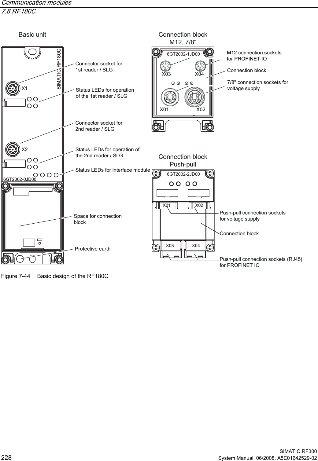
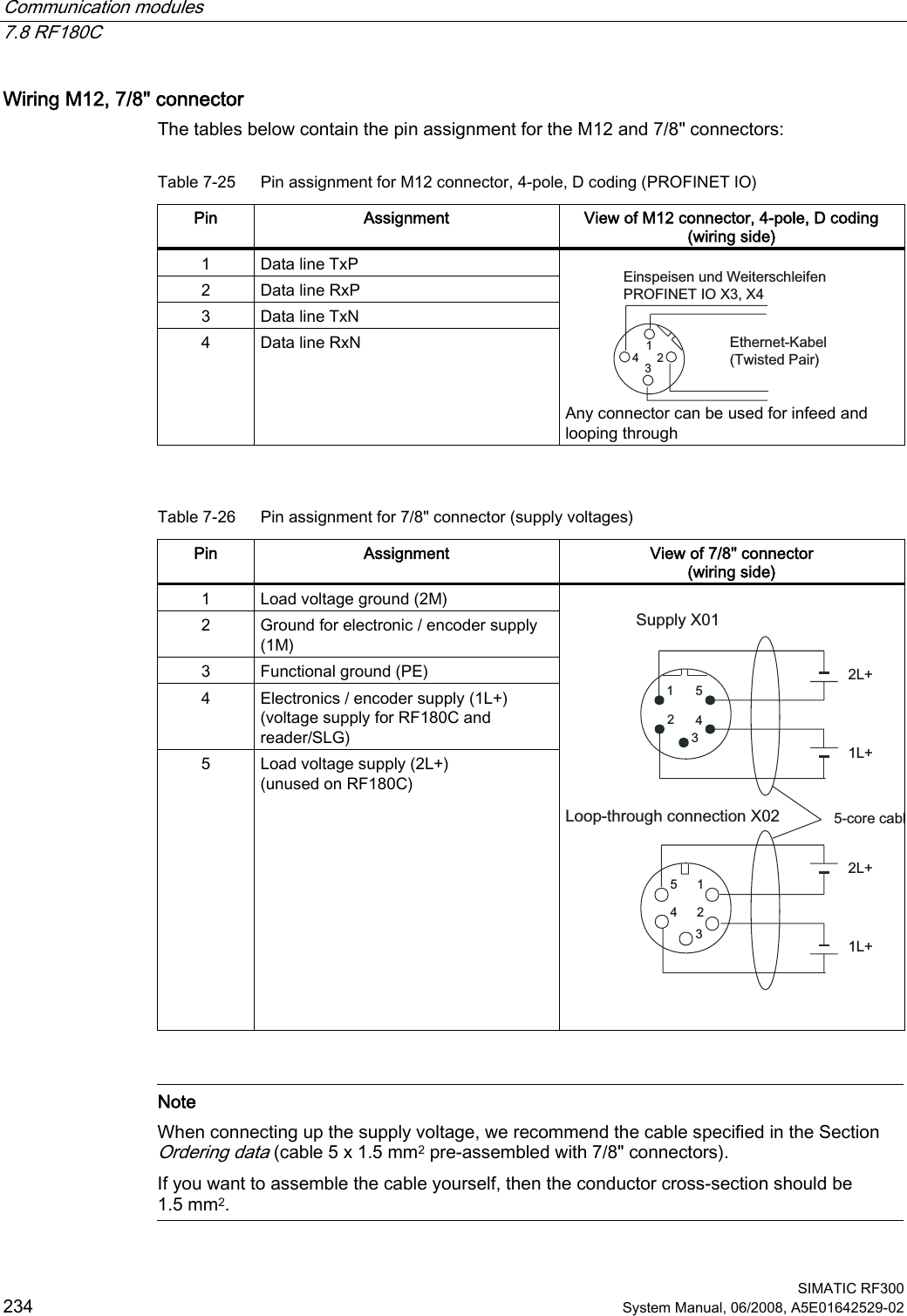
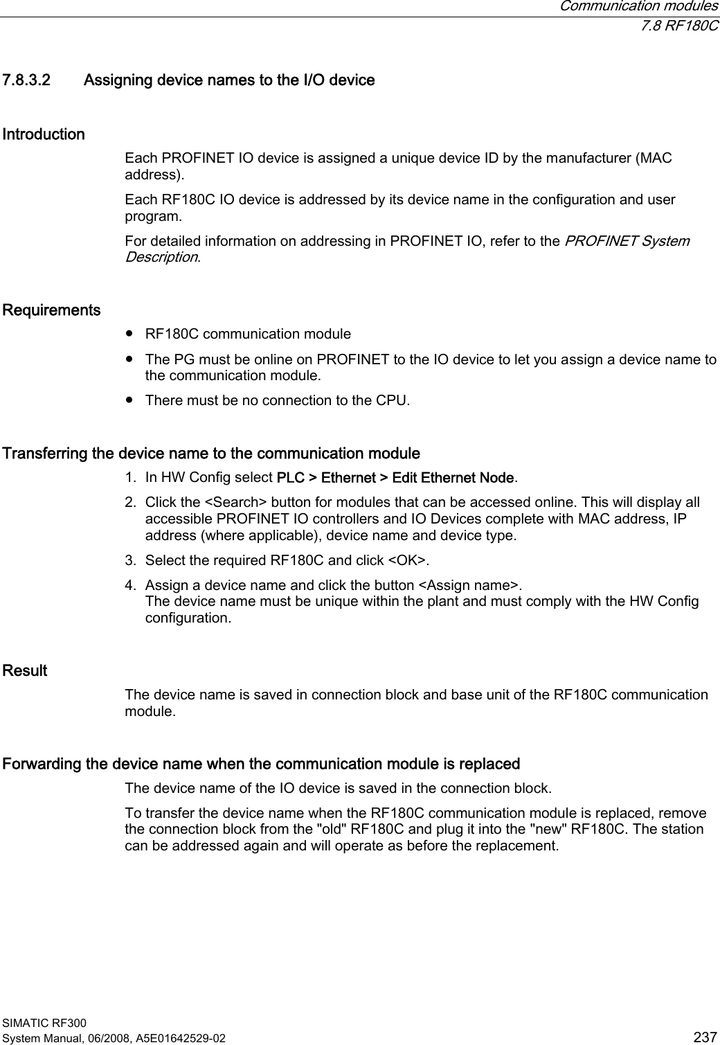
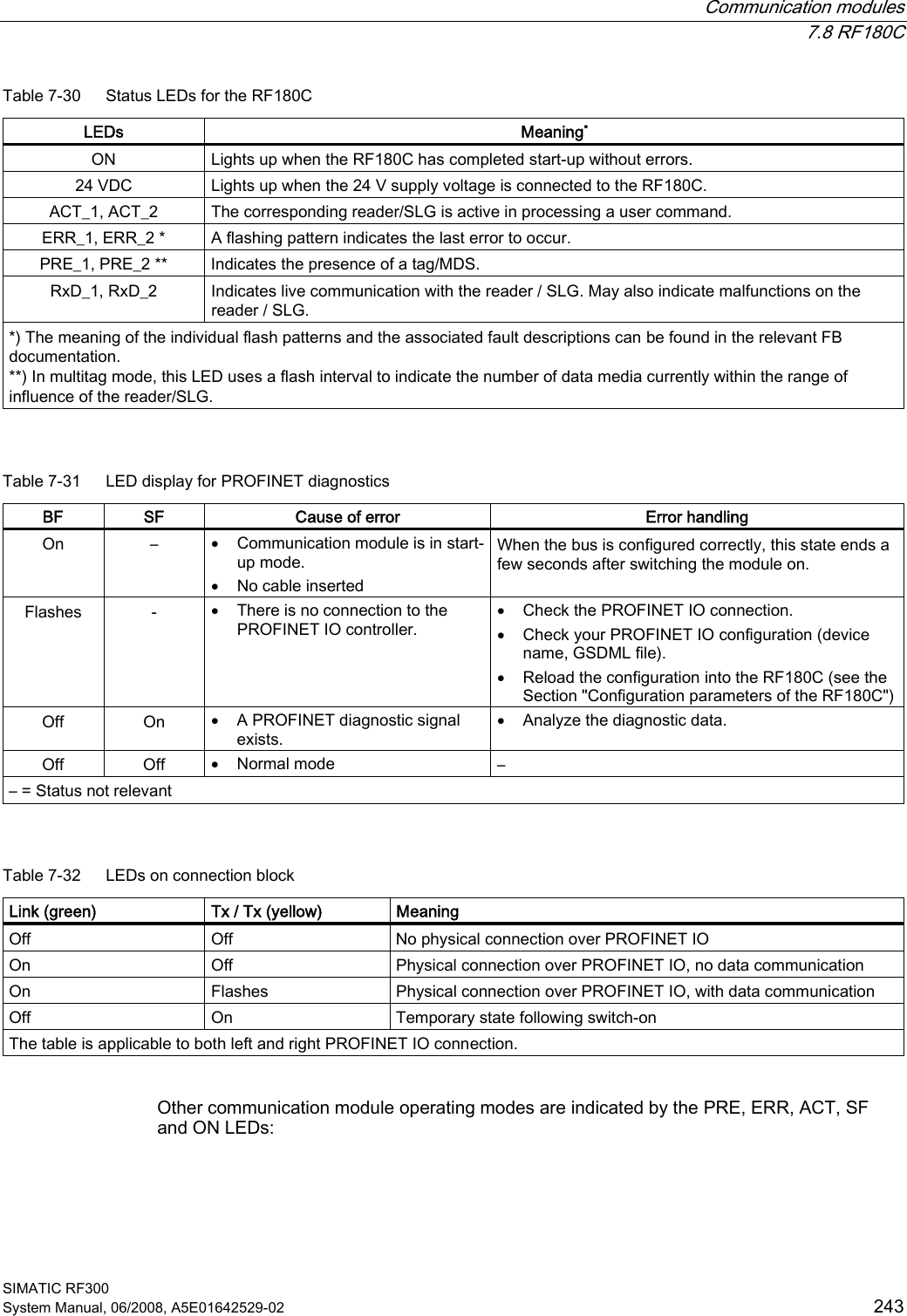
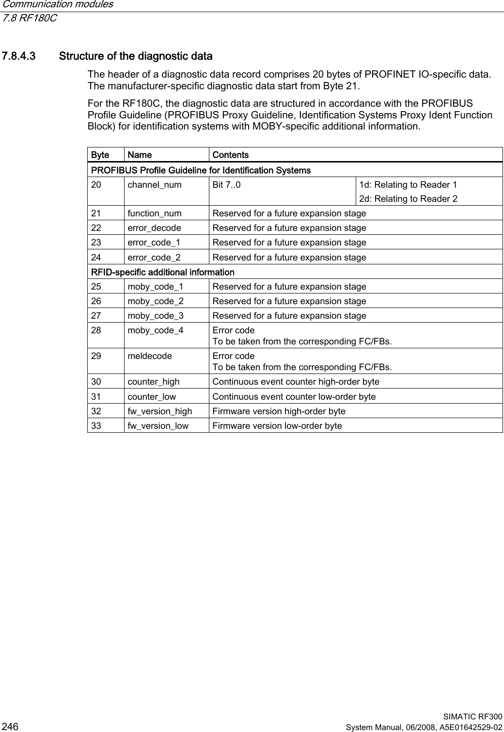
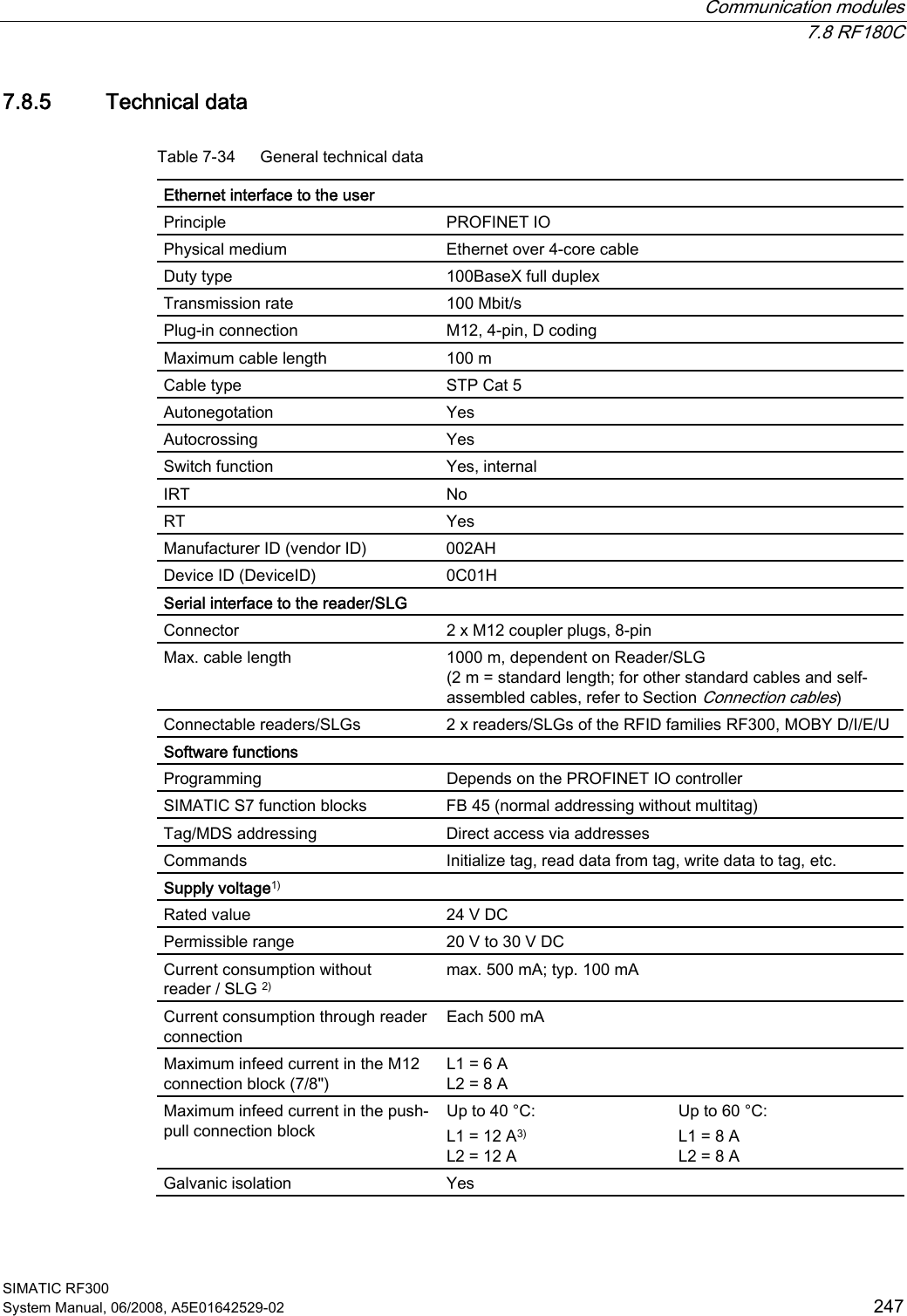
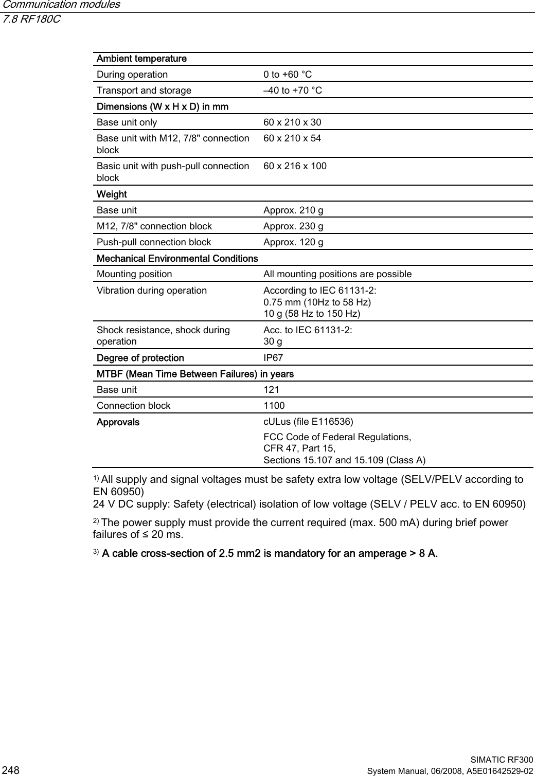
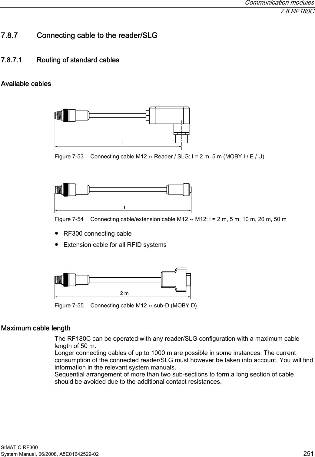
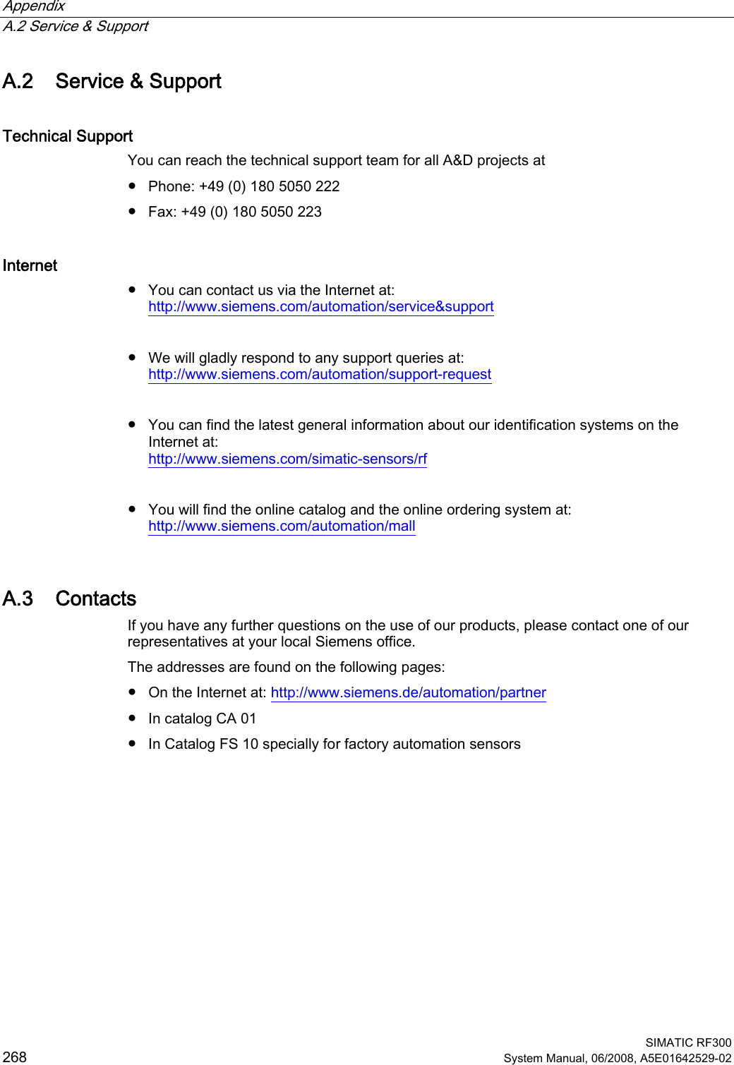
![Communication modules 7.8 RF180C SIMATIC RF300 System Manual, 06/2008, A5E01642529-02 229 Potential Ungrounded installation of the system is possible with the RF180C. The following circuit shows the internal relationships of the reference potentials. 0˖0˖0˖Q)Q)Q) Q)0006FKLUP99HUVRUJXQJ5)&XQG5HDGHU,QWHUQH9HUVRUJXQJ5HDGHU6FKQLWWVWHOOH352),1(7,2+LOIVVSDQQXQJI¾U%XVDQVFKOXVV Figure 7-45 Galvanic isolation of RF180C Integration The following figure shows how the RF180C with M12 connection block (7/8") is integrated in an automation system. The push-pull connection block is integrated in the same manner as the M12 connection block (7/8"). 6WHXHUXQJ]%6&38352),1(7,2/HLWXQJ]XZHLWHUHQ352),1(7,27HLOQHKPHUQ9I¾U5)&XQG5HDGHU6/*5HDGHU 5HDGHU7UDQVSRQGHU;;5)& Figure 7-46 RF180C configurator with M12 connection block (7/8")](https://usermanual.wiki/Siemens/RF310R.User-Manual-IV/User-Guide-986216-Page-9.png)