Siemens RF310R Tag Reader User Manual SIMATIC Sensors RFID systems SIMATIC RF300
Siemens AG Tag Reader SIMATIC Sensors RFID systems SIMATIC RF300
Siemens >
Contents
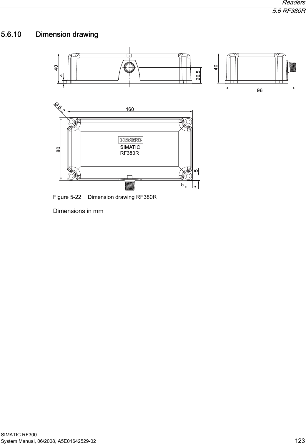
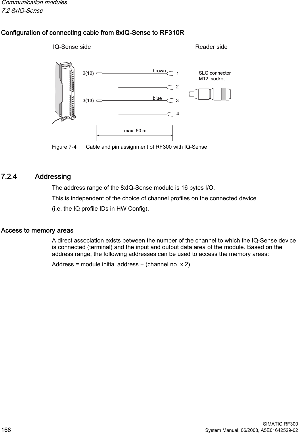
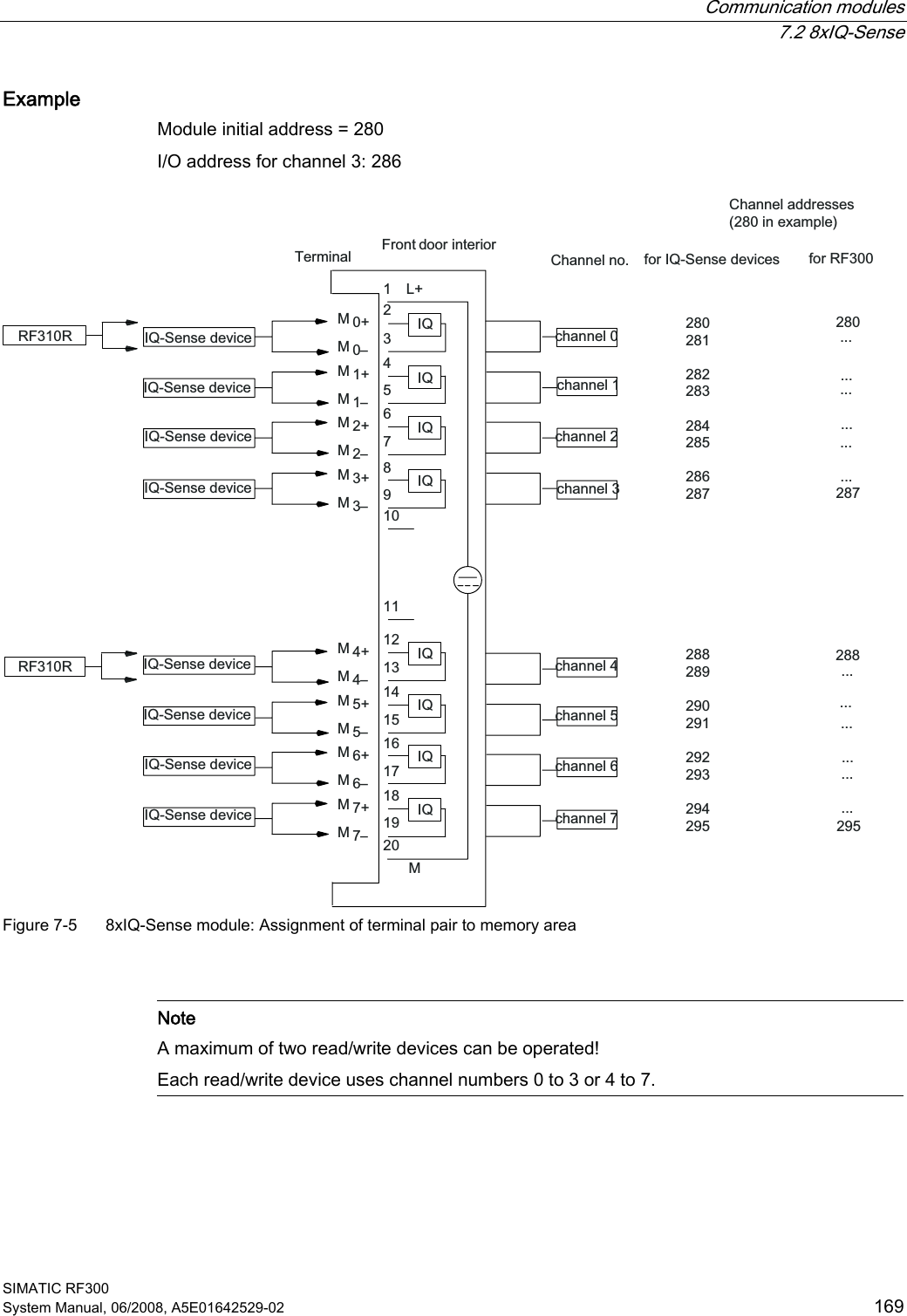
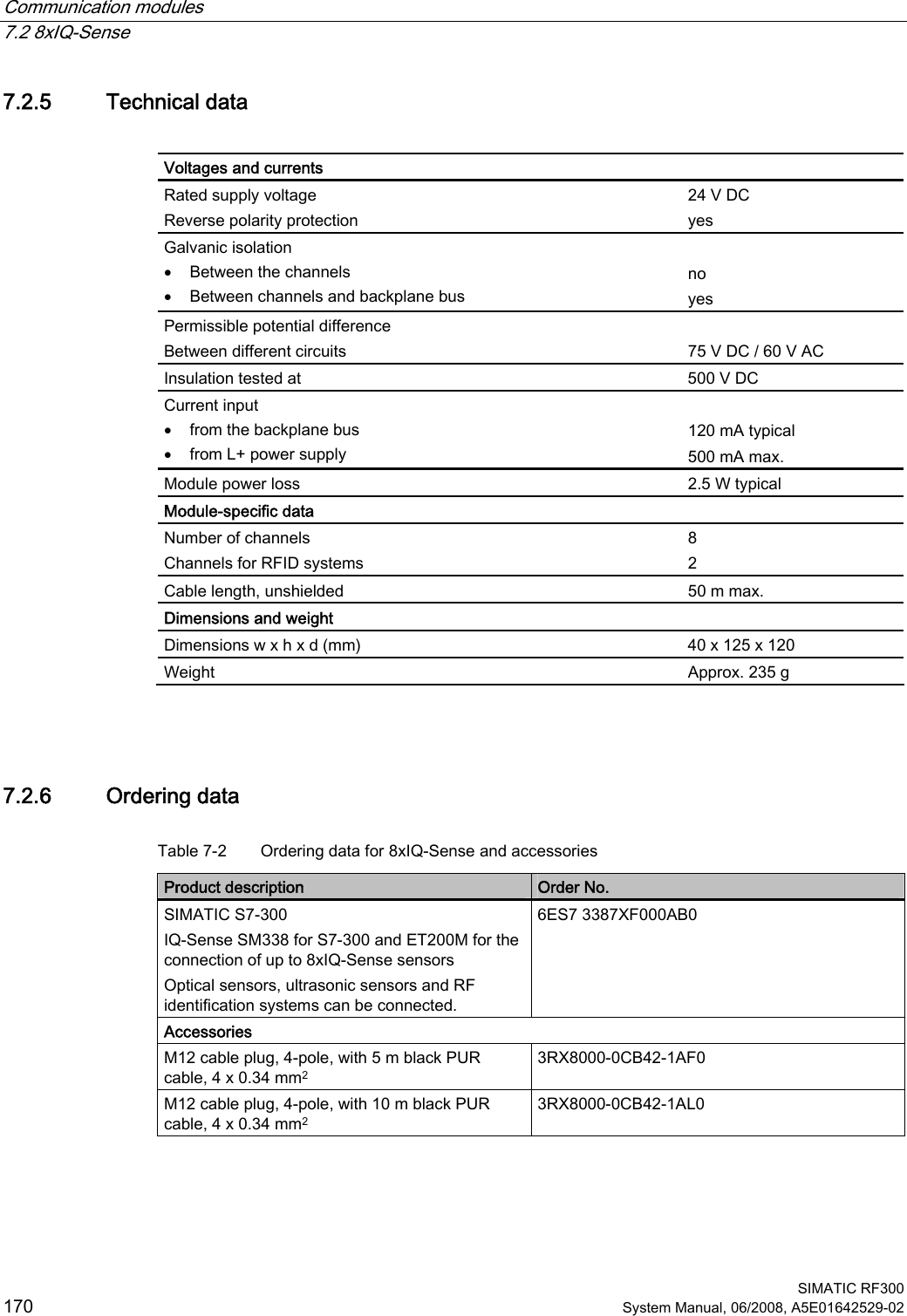
- 1. User Manual I
- 2. User Manual II
- 3. User Manual III
- 4. User Manual IV
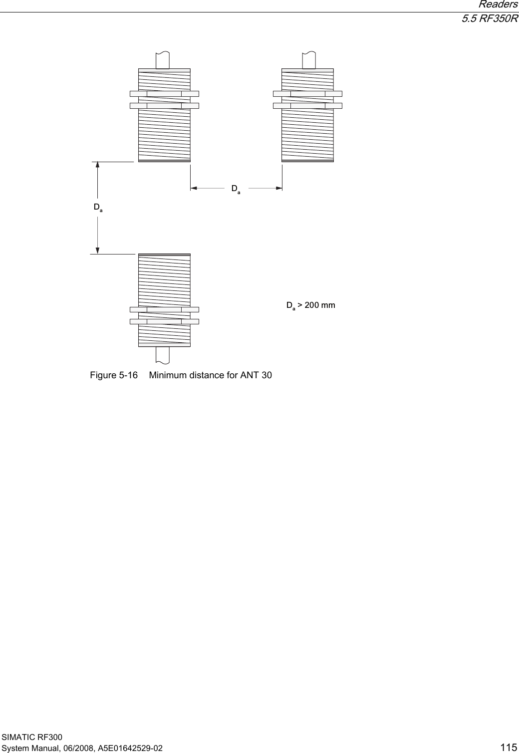
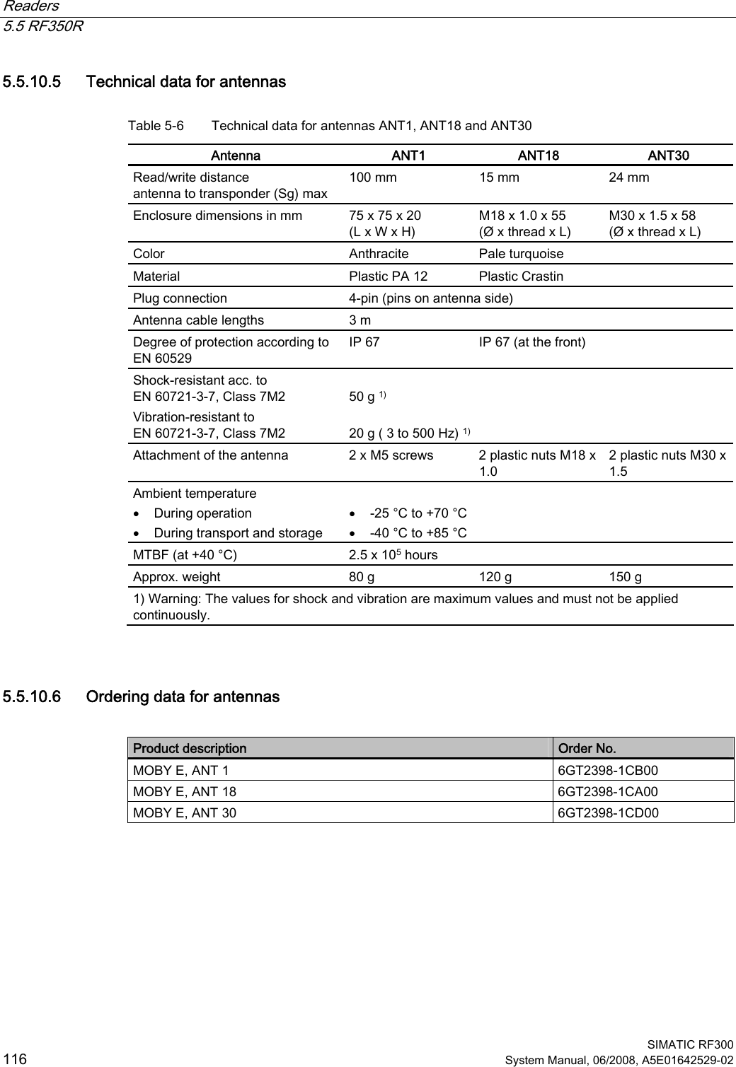
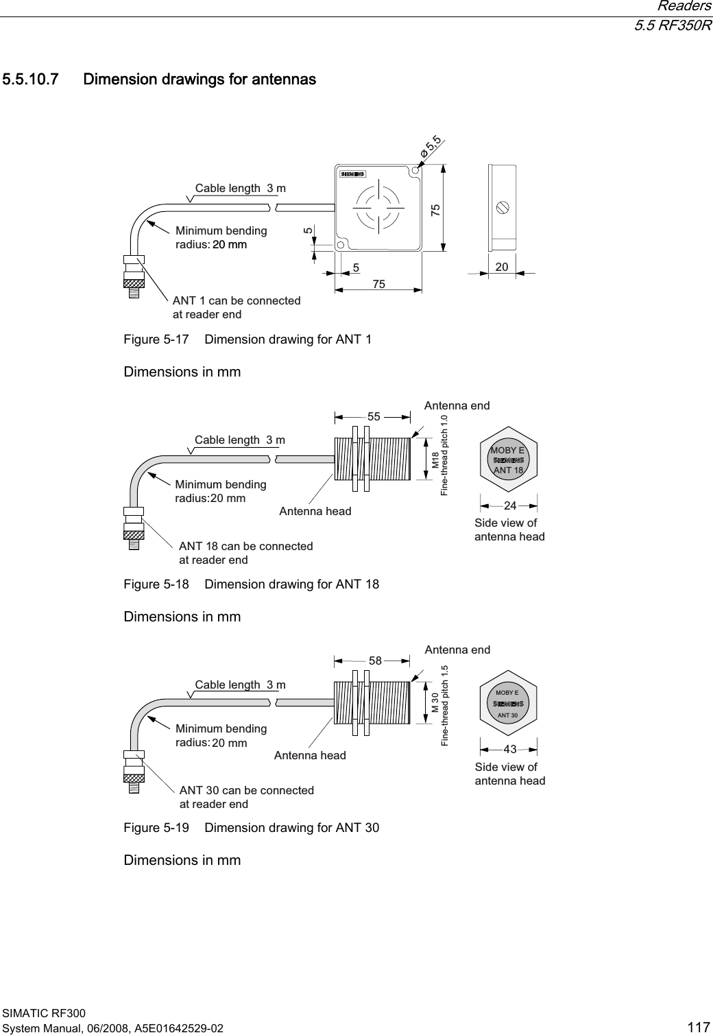
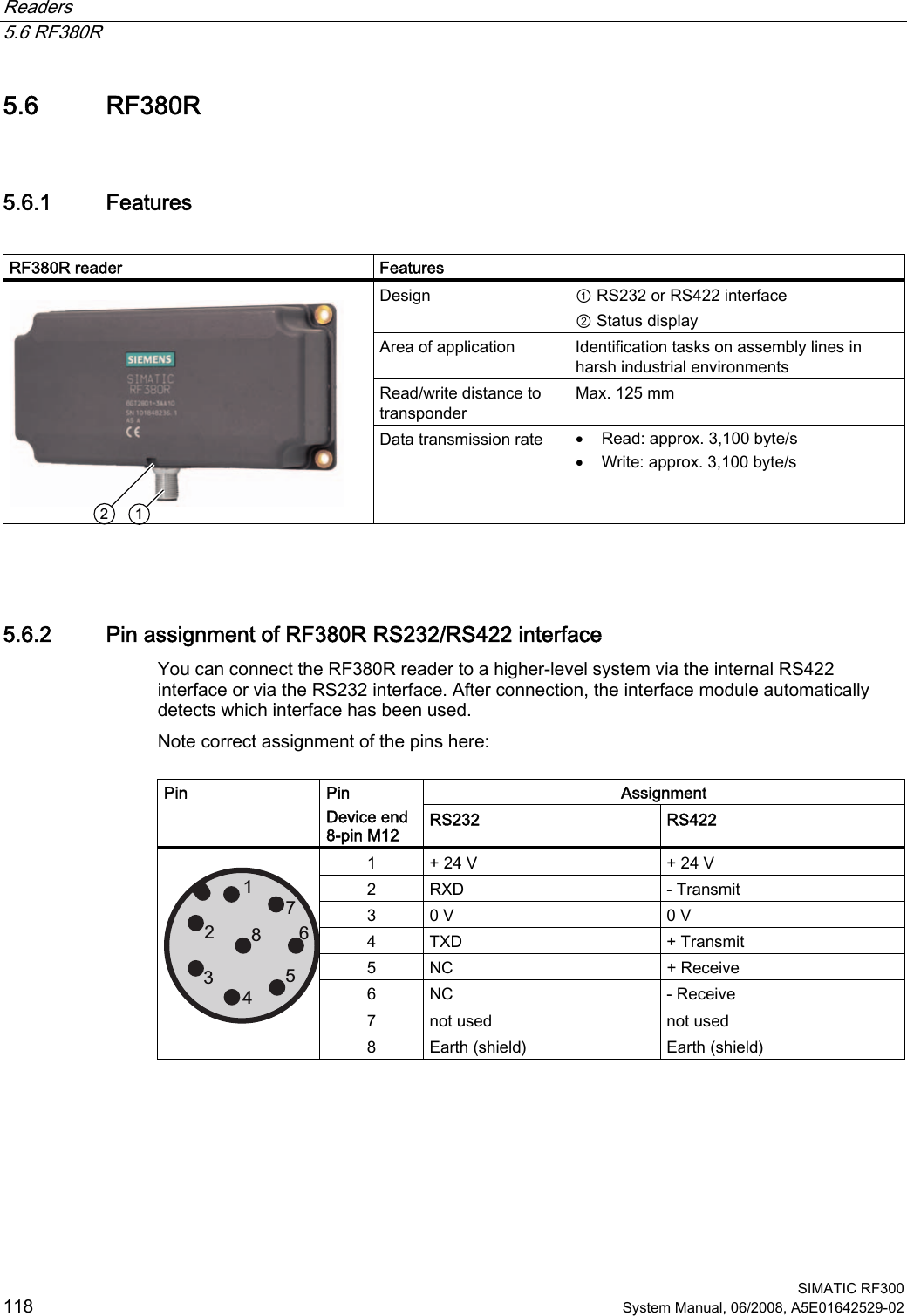
User Manual II