Siemens RF310R Tag Reader User Manual SIMATIC Sensors RFID systems SIMATIC RF300
Siemens AG Tag Reader SIMATIC Sensors RFID systems SIMATIC RF300
Siemens >
Contents
- 1. User Manual I
- 2. User Manual II
- 3. User Manual III
- 4. User Manual IV
User Manual II

Readers
5.5 RF350R
SIMATIC RF300
System Manual, 06/2008, A5E01642529-02 111
ANT 30
The ANT 30 is designed for use in small assembly lines. In comparison to ANT 18, the
maximum write/read distance is approximately 60 % larger. Due to its compact construction,
the antenna can be easily positioned for any application using two plastic nuts (included in
the package). The antenna cable can be connected at the reader end. With the RF320T,
RF340T and RF350T tags, communication with the data storage unit is only possible in static
mode.
5.5.10.2 Ensuring reliable data exchange
The "center point" of the transponder must be situated within the transmission window.
Readers
5.5 RF350R
SIMATIC RF300
112 System Manual, 06/2008, A5E01642529-02
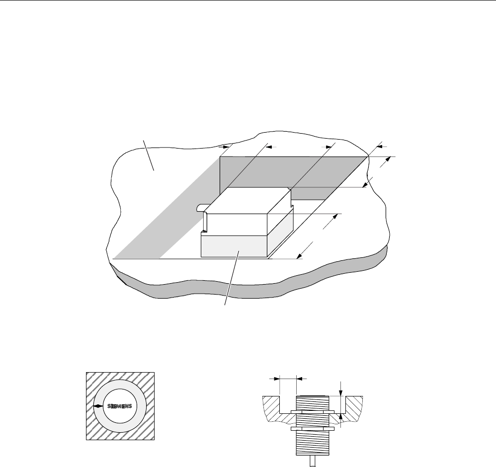
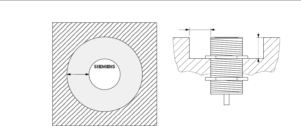
5.5.10.3 Metal-free area
The antennas ANT1, ANT18 and ANT30 can be flush-mounted on metal. Please allow for a
possible reduction in the field data values.
0HWDOIUHHDUHDIRUIOXVKPRXQWLQJ
QRWDPHWDOOLFEDVH
0HWDO
a = 40 mm
h > 20 mm
a
a
a
a
h > 20 mm
Figure 5-11 Metal-free area for ANT 1
1RWH
,IWKHPHWDOIUHHDUHDLVQRW
REVHUYHGWKHOLPLWDQGRSHUDWLQJ
GLVWDQFHVDUHUHGXFHG
0HWDOIUHHDUHDIRU
IOXVKPRXQWLQJ
D
E
D PP
E PP
$17
02%<(
$17
D
Figure 5-12 Metal-free area for ANT 18
Readers
5.5 RF350R
SIMATIC RF300
System Manual, 06/2008, A5E01642529-02 113
D
E
D PP
E PP
D02%<(
$17
3ODQYLHZ
6LGHYLHZ
Figure 5-13 Metal-free area for ANT 30
Readers
5.5 RF350R
SIMATIC RF300
114 System Manual, 06/2008, A5E01642529-02
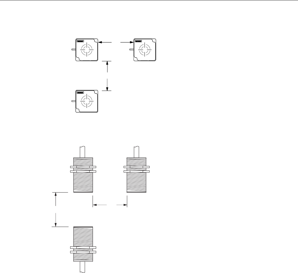
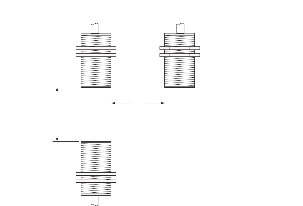
5.5.10.4 Minimum distance between antennas
7KHUHDGHUHOHFWURQLFVFDQEH
PRXQWHGGLUHFWO\DORQJVLGHHDFKRWKHU
$
17
E
'PP
D!
B
$17
$17
'PP
!
B
'
D
E
'
Figure 5-14 Minimum distance for ANT 1
'
D
ุPP
'
D
'
D
Figure 5-15 Minimum distance for ANT 18
Readers
5.5 RF350R
SIMATIC RF300
System Manual, 06/2008, A5E01642529-02 115
'
D
!PP
'
D
'
D
Figure 5-16 Minimum distance for ANT 30

Readers
5.5 RF350R
SIMATIC RF300
116 System Manual, 06/2008, A5E01642529-02
5.5.10.5 Technical data for antennas
Table 5-6 Technical data for antennas ANT1, ANT18 and ANT30
Antenna ANT1 ANT18 ANT30
Read/write distance
antenna to transponder (Sg) max
100 mm 15 mm 24 mm
Enclosure dimensions in mm 75 x 75 x 20
(L x W x H)
M18 x 1.0 x 55
(Ø x thread x L)
M30 x 1.5 x 58
(Ø x thread x L)
Color Anthracite Pale turquoise
Material Plastic PA 12 Plastic Crastin
Plug connection 4-pin (pins on antenna side)
Antenna cable lengths 3 m
Degree of protection according to
EN 60529
IP 67 IP 67 (at the front)
Shock-resistant acc. to
EN 60721-3-7, Class 7M2
Vibration-resistant to
EN 60721-3-7, Class 7M2
50 g 1)
20 g ( 3 to 500 Hz) 1)
Attachment of the antenna 2 x M5 screws 2 plastic nuts M18 x
1.0
2 plastic nuts M30 x
1.5
Ambient temperature
• During operation
• During transport and storage
• -25 °C to +70 °C
• -40 °C to +85 °C
MTBF (at +40 °C) 2.5 x 10⁵ hours
Approx. weight 80 g 120 g 150 g
1) Warning: The values for shock and vibration are maximum values and must not be applied
continuously.
5.5.10.6 Ordering data for antennas
Product description Order No.
MOBY E, ANT 1 6GT2398-1CB00
MOBY E, ANT 18 6GT2398-1CA00
MOBY E, ANT 30 6GT2398-1CD00
Readers
5.5 RF350R
SIMATIC RF300
System Manual, 06/2008, A5E01642529-02 117
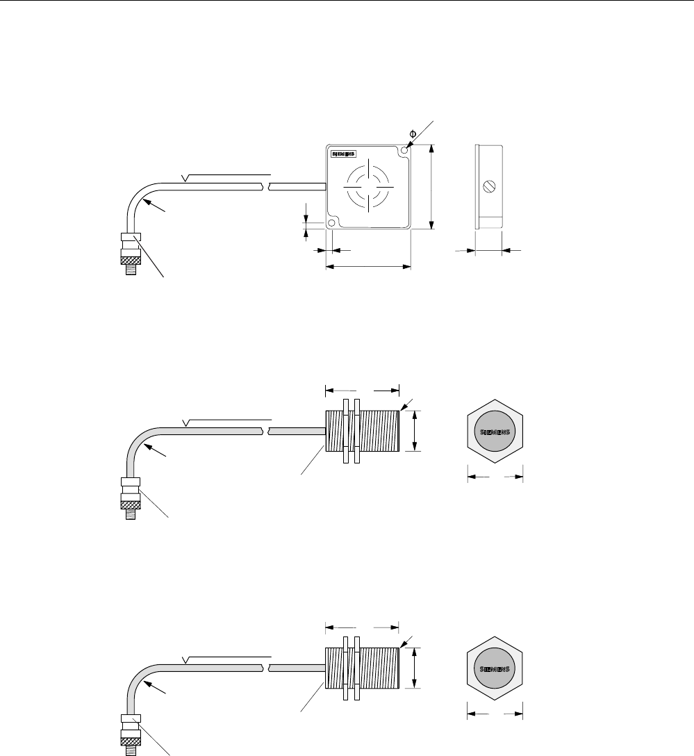
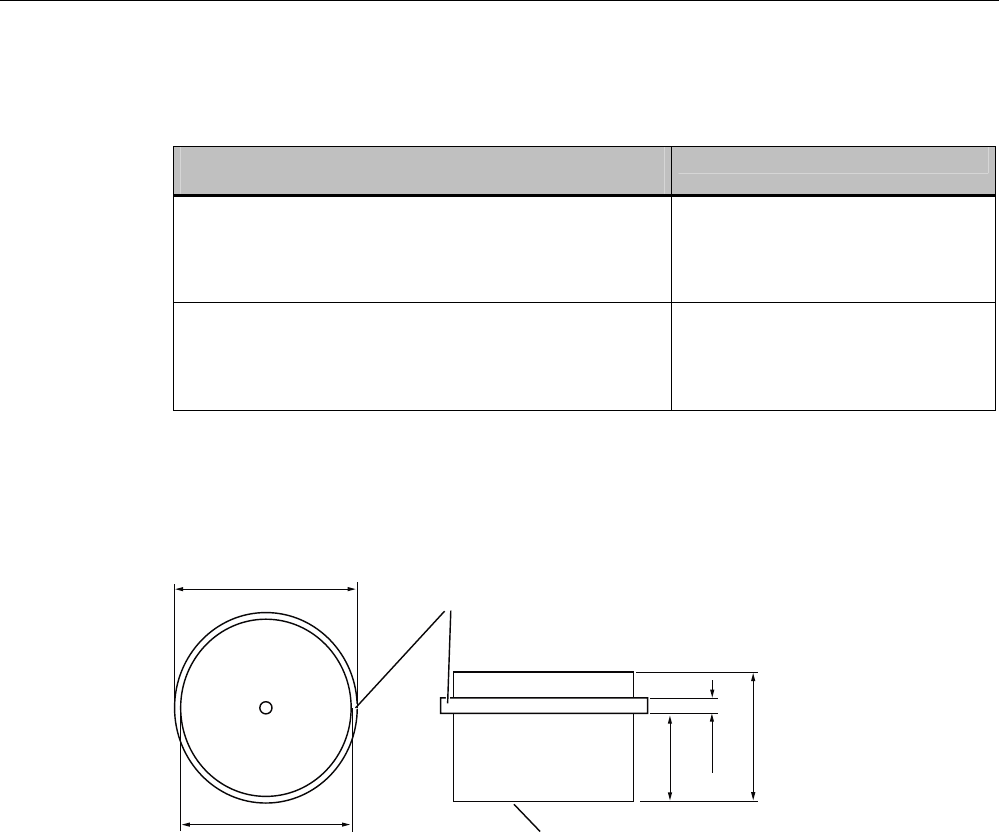
5.5.10.7 Dimension drawings for antennas
&DEOHOHQJWKP
0LQLPXPEHQGLQJ
UDGLXV
$17FDQEHFRQQHFWHG
DWUHDGHUHQG
20 mm
Figure 5-17 Dimension drawing for ANT 1
Dimensions in mm
&DEOHOHQJWKP
0LQLPXPEHQGLQJ
UDGLXV
$17FDQEHFRQQHFWHG
DWUHDGHUHQG
$QWHQQDKHDG
6LGHYLHZRI
DQWHQQDKHDG
$QWHQQDHQG
)LQHWKUHDGSLWFK
PP
0
02%<(
$17
Figure 5-18 Dimension drawing for ANT 18
Dimensions in mm
&DEOHOHQJWKP
0LQLPXPEHQGLQJ
UDGLXV
$17FDQEHFRQQHFWHG
DWUHDGHUHQG
$QWHQQDKHDG
6LGHYLHZRI
DQWHQQDKHDG
$QWHQQDHQG
)LQHWKUHDGSLWFK
PP
0
$17
02%<(
Figure 5-19 Dimension drawing for ANT 30
Dimensions in mm
Readers
5.6 RF380R
SIMATIC RF300
118 System Manual, 06/2008, A5E01642529-02
5.6 RF380R
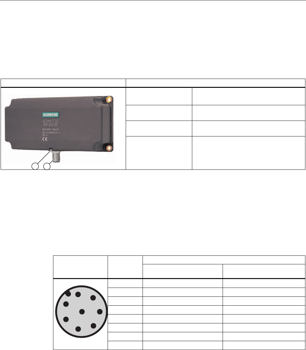
5.6.1 Features
RF380R reader Features
Design ① RS232 or RS422 interface
② Status display
Area of application Identification tasks on assembly lines in
harsh industrial environments
Read/write distance to
transponder
Max. 125 mm
Data transmission rate • Read: approx. 3,100 byte/s
• Write: approx. 3,100 byte/s
5.6.2 Pin assignment of RF380R RS232/RS422 interface
You can connect the RF380R reader to a higher-level system via the internal RS422
interface or via the RS232 interface. After connection, the interface module automatically
detects which interface has been used.
Note correct assignment of the pins here:
Assignment Pin Pin
Device end
8-pin M12 RS232 RS422
1 + 24 V + 24 V
2 RXD - Transmit
3 0 V 0 V
4 TXD + Transmit
5 NC + Receive
6 NC - Receive
7 not used not used
8 Earth (shield) Earth (shield)
Readers
5.6 RF380R
SIMATIC RF300
System Manual, 06/2008, A5E01642529-02 119
5.6.3 Display elements of the RF380R reader
Color Meaning
Flashing Operating voltage present, reader not initialized or antenna switched offGreen
Permanently
on
Operating voltage present, reader initialized and antenna switched on
Yellow1) Transponder present
Flashing red Error has occurred, the type of flashing corresponds to the error code in
the table in Section "Error codes". The optical error display is only reset
if the corresponding reset parameter ("option_1", see FC45 / FB45
documentation, Section "Input parameters") is set.
1) In the operating state "Without presence", the lighting duration may be very short.
5.6.4 Ensuring reliable data exchange
The "center point" of the transponder must be situated within the transmission window.
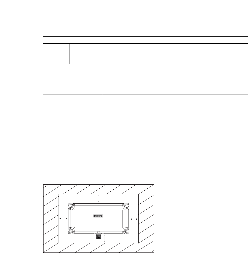
5.6.5 Metal-free area
The RF380R can be flush-mounted in metal. Please allow for a possible reduction in the field
data values.
D
D
D
D
6,0$7,&
5)5
Figure 5-20 Metal-free area for RF380R
To avoid any impact on the field data, the distance a should be ≥ 20 mm.
Readers
5.6 RF380R
SIMATIC RF300
120 System Manual, 06/2008, A5E01642529-02
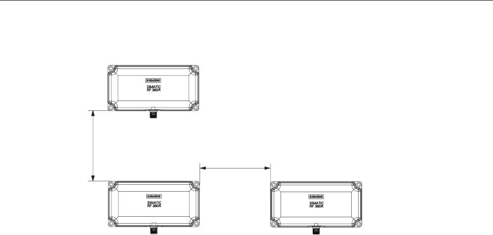
5.6.6 Minimum distance between RF380R readers
ุPP
0LQLPXPGLVWDQFHEHWZHHQ5)5DQG5)5
'
'
'
Figure 5-21 Minimum distance between RF380R readers

Readers
5.6 RF380R
SIMATIC RF300
System Manual, 06/2008, A5E01642529-02 121
5.6.7 Technical specifications of the RF380R reader
Table 5-7 Technical specifications of the RF380R reader
Inductive interface to the transponder
Transmission frequency for power/data
13.56 MHz
Antenna integrated
Interface to communication module RS232 or RS422 (3964R protocol)
Baud rate 19200 baud, 57600 baud, 115200 baud
Cable length between reader and communication
module
RS422 data cable length: max. 1000 m
RS232 data cable length: Max. 30 m
Read/write distances of reader See RF380R field data
Minimum distance between two RF380R readers ≥ 500 mm
Maximum data transfer rate
reader - transponder (tag)
Reading
Writing
Approx. 3100 byte/s
Approx. 3100 byte/s
Functions Initialize/read/write transponder
Scan status and diagnostics information
Switch antenna on/off
Repeat command
Scan transponder serial numbers
Power supply 24 V DC
Display elements 2-color LED
(operating voltage, presence, error)
Plug connector M12 (8-pin)
Enclosure
Dimensions (in mm)
Color
Material
160 x 80 x 40 (without M12 plug connector)
Anthracite
Plastic PA 12
Fixing 4 x M5 screws
Ambient temperature during operation
during transport and storage
-25 °C to +70 °C
-40 °C to +85 °C
Degree of protection to EN 60529
Shock to EN 60 721-3-7 Class 7 M2
Vibration to EN 60 721-3-7 Class 7 M2
IP67
50 g
20 g
Weight Approx. 600 g
MTBF (Mean Time Between Failures) in years 109 years
Approvals Radio to R&TTE guidelines EN 300 330,
EN 301489, CE, FCC, UL/CSA
Current consumption Typ. 160 mA

Readers
5.6 RF380R
SIMATIC RF300
122 System Manual, 06/2008, A5E01642529-02
5.6.8 FCC information
Siemens SIMATIC RF380R
FCC ID: NXW-RF380R
This device complies with part 15 of the FCC rules. Operation is subject to the following two
conditions:
(1) This device may not cause harmful interference.
(2) This device must accept any interference received, including interference that may cause
undesired operation.
Caution
Any changes or modifications not expressly approved by the party responsible for
compliance could void the user's authority to operate the equipment.
5.6.9 RF380R ordering data
Product description Order No.
Reader RF380R
With RS422 interface (3964R)
IP67;
-25 °C to +70 °C, dimensions 160 x 96 x 40 (L x W x H in mm);
with integrated antenna;
max. limit distance 150 mm (depending on transponder)
6GT2801-3AA10
Readers
5.6 RF380R
SIMATIC RF300
System Manual, 06/2008, A5E01642529-02 123
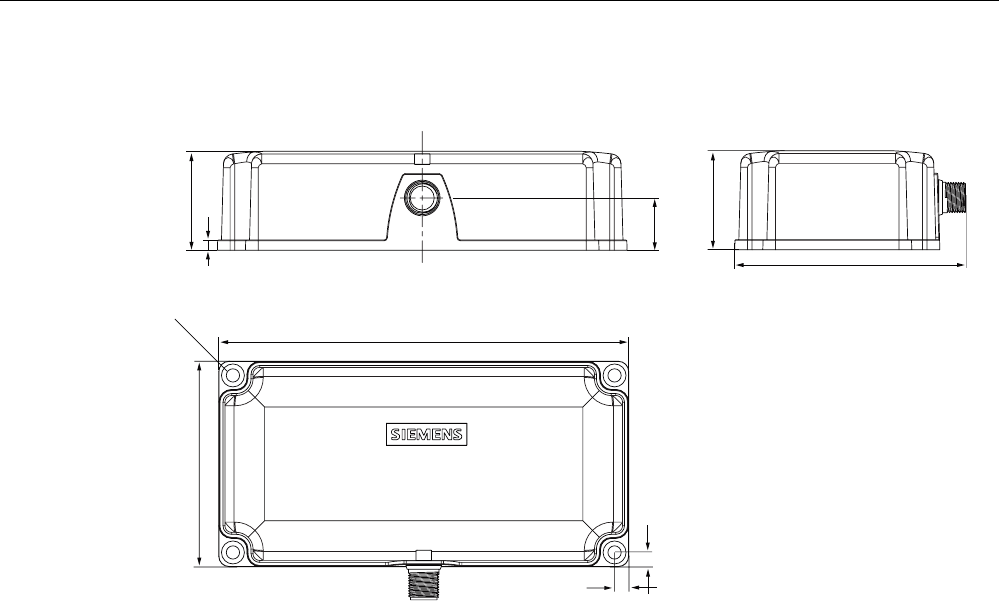
5.6.10 Dimension drawing
6,0$7,&
5)5
Figure 5-22 Dimension drawing RF380R
Dimensions in mm

Readers
5.6 RF380R
SIMATIC RF300
124 System Manual, 06/2008, A5E01642529-02
SIMATIC RF300
System Manual, 06/2008, A5E01642529-02 125
Transponders 6
6.1 Overview
Transponders consist predominantly of logic, FRAM and/or EEPROM.
If a transponder moves into the transmission window of the reader, the necessary power for
all of the circuit components is generated and monitored by the power supply unit. The
pulse-coded information is prepared in such a way that it can be processed further as pure
digital signals. The handling of data, including check routines, is performed by the logic,
which also manages the various memories.
Transponders
6.2 RF320T
SIMATIC RF300
126 System Manual, 06/2008, A5E01642529-02
6.2 RF320T
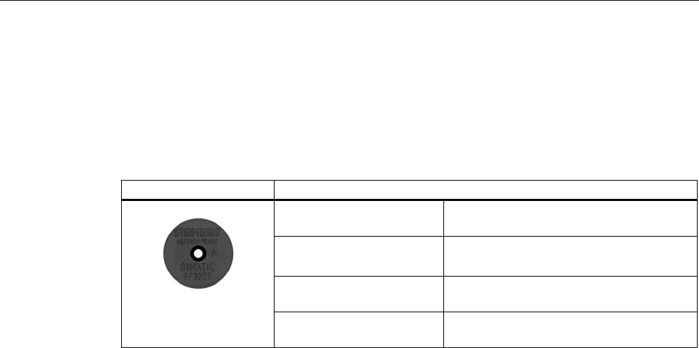
6.2.1 Features
Transponder RF320T Features
Field of application Identification tasks on small assembly lines
in harsh industrial environments
Memory Read-only area (4 bytes UID)
User data area (20 bytes)
Read/write range See Section Field data for transponders,
readers and antennas (Page 39)
Mounting on metal Not possible Recommended distance from
metal ≥ 20 mm
Transponders
6.2 RF320T
SIMATIC RF300
System Manual, 06/2008, A5E01642529-02 127
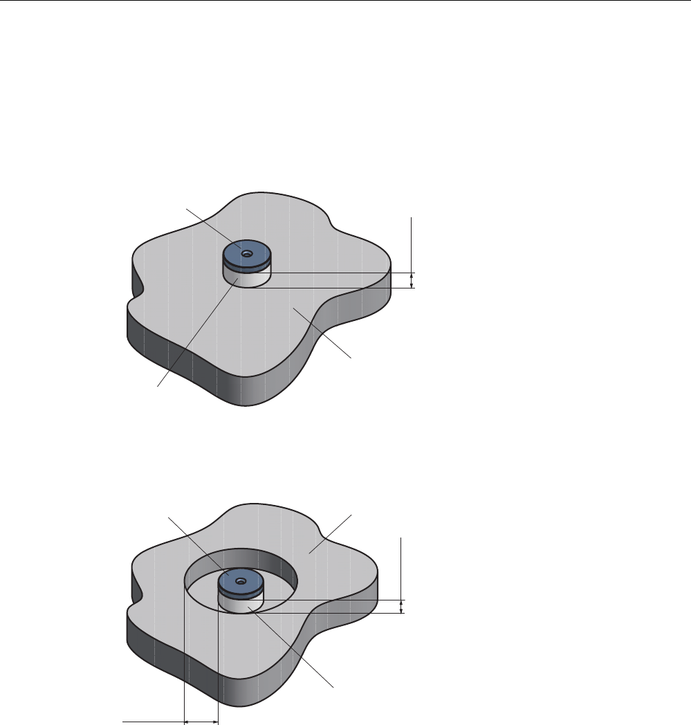
6.2.2 Metal-free area
Mounting of RF320T on metal
Direct mounting of the RF320T on metal is not allowed.
The following figures show the minimum distance between the RF320T and metal:
1RQPHWDO
0HWDO
K!PP
'DWDPHPRU\
Figure 6-1 Mounting of an RF320T on metal with spacer
Flush-mounting of RF320T in metal
D!PP
K!PP
'DWDPHPRU\ 0HWDO
1RQPHWDO
Figure 6-2 Flush-mounting of RF320T in metal with spacer
At lower values, the field data change significantly, resulting in a reduced range.

Transponders
6.2 RF320T
SIMATIC RF300
128 System Manual, 06/2008, A5E01642529-02
6.2.3 Technical data
Table 6-1 Technical data for RF320T
Memory size 20 bytes EEPROM (r/w), 4 bytes UID (ro)
Memory organization Byte-oriented access, write protection possible
in 4-byte blocks
MTBF (Mean Time Between Failures) in years 1871
Read cycles Unlimited
Write cycles, min. 50 000
at ≤ 40 °C, typical > 100 000
Data retention time > 10 years (at < +40 °C)
Write/read distance dependent on the reader used
(see field data)
Energy source Inductive power transmission
Shock/vibration-resistant to EN 60721-3-7, Class 7
M3
100 g/20 g
Torsion and bending load not permissible
Fixing Adhesive/M3 screws
Recommended spacing from metal > 20 mm
Degree of protection to EN 60529 • IP67/IPX9K
Housing
• Dimensions
• Color/material
Button
• Ø 27 mm x 4 mm
• Black/epoxy resin
Ambient temperature
• Operation
• Transport and storage
• -25 to +85 °C
• -40 to +125 °C
Weight Approx. 5 g
Note
All the technical data listed are typical data and are applicable for an ambient temperature of
between 0 C and +50°C and a metal-free environment.
6.2.4 Ordering data
Transponder RF320T Order No.
Transponder RF320T, button, 20 byte EEPROM,
IP 67, -25 °C to +85 °C, d = 27 mm x 4 mm
6GT2800-1CA00

Transponders
6.2 RF320T
SIMATIC RF300
System Manual, 06/2008, A5E01642529-02 129
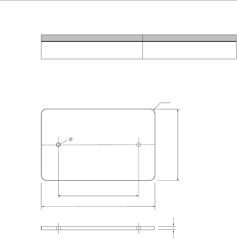
6.2.5 Dimension drawing
Figure 6-3 RF320T dimension drawing
Dimensions in mm
Transponders
6.3 RF340T
SIMATIC RF300
130 System Manual, 06/2008, A5E01642529-02
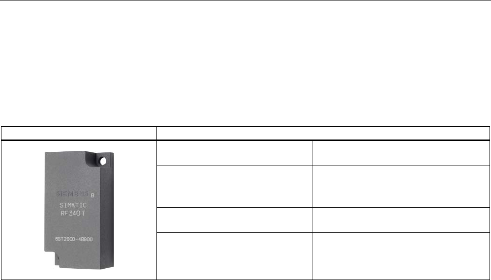
6.3 RF340T
6.3.1 Features
Transponder RF340T Features
Field of application Identification tasks on small assembly lines
in harsh industrial environments
Memory Read-only area (4 bytes UID)
Read/write memory (8 KB)
OTP 1) memory (20 bytes)
Read/write range See Section Field data for transponders,
readers and antennas (Page 39)
Mounting on metal Direct mounting on metal is possible.
1) OTP: (One Time Programmable)
Transponders
6.3 RF340T
SIMATIC RF300
System Manual, 06/2008, A5E01642529-02 131
6.3.2 Metal-free area
Direct mounting of the RF340T on metal is permitted.
Mounting of RF340T on metal
0HWDO
Figure 6-4 Mounting of RF340T on metal
Flush-mounting of RF340T in metal:
D
D
0HWDO
Figure 6-5 Flush-mounting of RF340T in metal
The standard value for a is ≥ 20 mm. At lower values, the field data change significantly,
resulting in a reduction in the range.

Transponders
6.3 RF340T
SIMATIC RF300
132 System Manual, 06/2008, A5E01642529-02
6.3.3 Technical specifications
Table 6-2 Technical specifications for RF340T
Memory size 8 KB
Memory organization Blocks of 8 bits / 1 byte
Memory configuration
• Serial number (UID)
• Application memory
• OPT memory
• 4-byte (fixed code)
• 8189 bytes r/w
• 20-byte OTP 1) memory
Storage technology FRAM / EEPROM
MTBF (Mean Time Between Failures) in years 1201
Write cycles, at +40°C Virtually unlimited (>1010)
Read cycles Virtually unlimited (>1010)
Transmission rate
• Read
• Write
with RS422 reader:
Approx. 0.3 ms / byte
approx. 0.3 ms / byte
with IQ-Sense reader:
Approx. 20 ms / byte
approx. 25 ms / byte
Data retention > 10 years
Read/write distance dependent on the reader used (see field data)
Multitag capability max. 4 transponders
Recommended spacing from metal can be directly mounted on metal
Power supply Inductive, without battery
Degree of protection to EN 60529
Shock to EN 60721-3-7
Vibration to EN 60721-3-7
Torsion and bending load
IP68/IPX9K
50 g
20 g
Not permitted permanently
Housing dimensions
Color
Material
Fixing
48 x 25 x 15 mm (L x W x H)
Anthracite
PA12
2 screws (M3)
Ambient temperature
• During operation
• Storage and transport
-25°C to +85°C
-40°C to +85°C
Weight Approx. 25 g
1) OTP: (One Time Programmable)
6.3.4 Ordering data
Transponder RF340T Order No.
Transponder RF340T, 8 KB FRAM, IP 68, -25 °C
to +85 °C, 48 x 25 x 15 mm (L x W x H)
6GT2800-4BB00
Transponders
6.3 RF340T
SIMATIC RF300
System Manual, 06/2008, A5E01642529-02 133
6.3.5 Dimension drawing
6,(0(16
6,0$7,&
5)7
Figure 6-6 RF340T dimension drawing
Dimensions in mm
Transponders
6.4 RF350T
SIMATIC RF300
134 System Manual, 06/2008, A5E01642529-02
6.4 RF350T
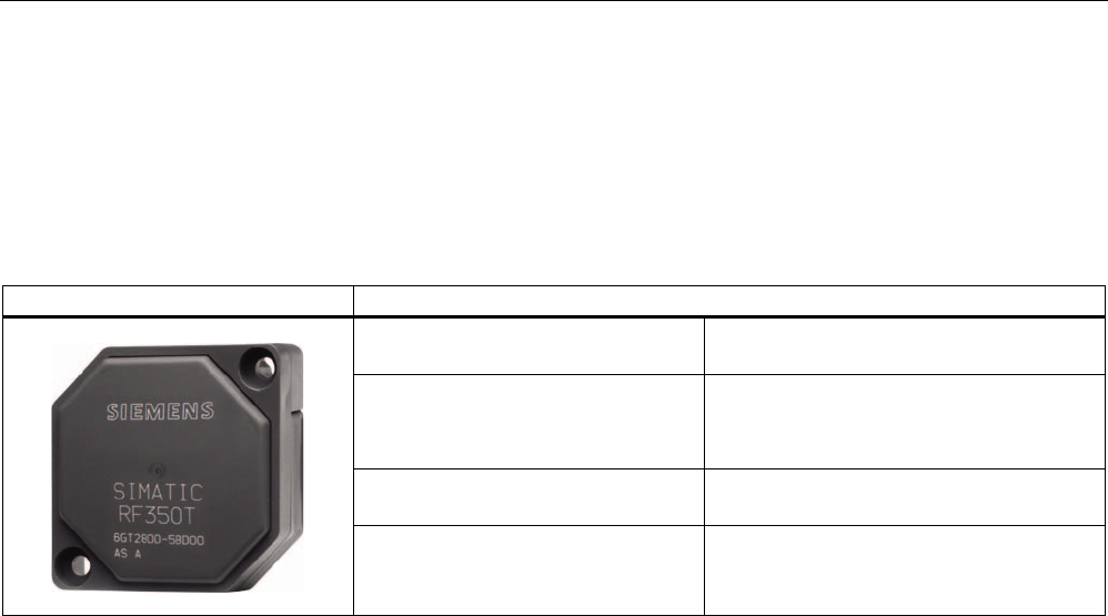
6.4.1 Features
Transponder RF350T Features
Field of application Identification tasks on small assembly lines
in harsh industrial environments
Memory Read-only area (4 bytes UID)
Read/write memory (32 KB)
OTP 1) memory (20 bytes)
Read/write range See Section Field data for transponders,
readers and antennas (Page 39)
Mounting on metal Direct mounting on metal is possible.
1) OTP: (One Time Programmable)
Transponders
6.4 RF350T
SIMATIC RF300
System Manual, 06/2008, A5E01642529-02 135
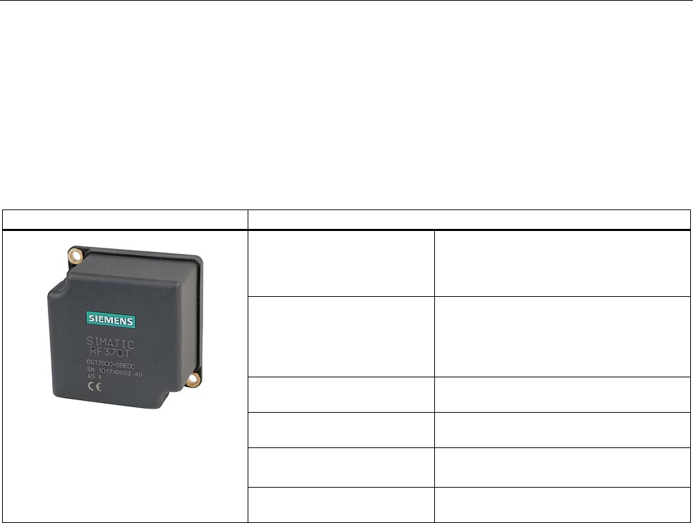
6.4.2 Metal-free area
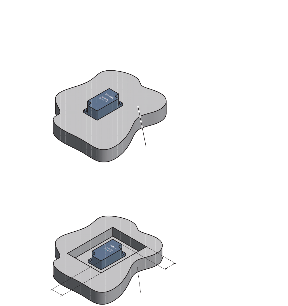
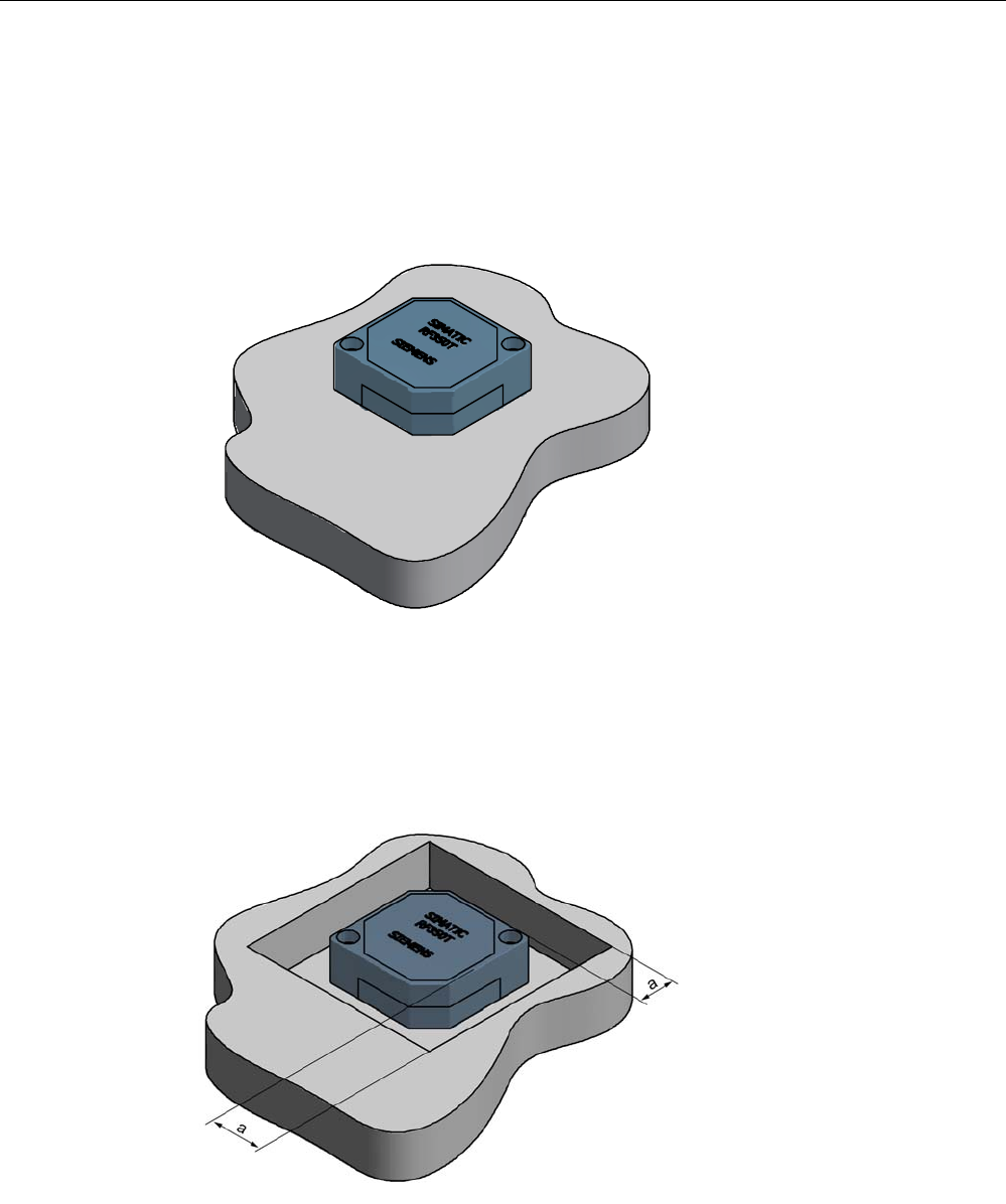
Direct mounting of the RF350T on metal is permitted.
Mounting of RF350T on metal
Figure 6-7 Mounting of RF350T on metal
Flush-mounting of RF350T in metal:
Figure 6-8 RF350T flush-mounted in metal
The standard value for a is ≥ 20 mm. At lower values, the field data change significantly,
resulting in a reduction in the range.

Transponders
6.4 RF350T
SIMATIC RF300
136 System Manual, 06/2008, A5E01642529-02
6.4.3 Technical data
Table 6-3 Technical specifications for RF350T
Memory size 32 KB
Memory organization Blocks of 8 bits / 1 byte
Memory configuration
• Serial number (UID)
• Application memory
• OTP 1) memory
• 4-byte (fixed code)
• 32765 bytes r/w
• 20 bytes
Storage technology FRAM / EEPROM
MTBF (Mean Time Between Failures) in years 1201
Write cycles, at +40°C Virtually unlimited (>1010)
Read cycles Virtually unlimited (>1010)
Transmission rate
• Reading
• Writing
with RS422 reader:
Approx. 0.3 ms / byte
approx. 0.3 ms / byte
with IQ-Sense reader:
Approx. 20 ms / byte
approx. 25 ms / byte
Data retention > 10 years
Read/write distance dependent on the reader used
(see field data)
Multitag capability max. 4 transponders
Recommended spacing from metal can be directly mounted on metal
Power supply Inductive, without battery
Degree of protection to EN 60529
Shock to EN 60721-3-7
Vibration to EN 60721-3-7
Torsion and bending load
IP68
50 g
20 g
Not permitted permanently
Enclosure dimensions
Color
Material
Fixing
50 x 50 x 20 mm (L x W x H)
Anthracite
PA12
2 screws M4
Ambient temperature
• During operation
• During transport and storage
-25 °C to +85 °C
-40 °C to +85 °C
Weight Approx. 25 g
1) OTP: (One Time Programmable)
6.4.4 Ordering data
RF350T Order No.
32 KB FRAM (read/write) + 4 byte EEPROM
(read only), IP 68, -25 °C to +85 °C, dimensions
50 x 50 x 20 (LxWxH in mm)
6GT2800-5BD00
Transponders
6.4 RF350T
SIMATIC RF300
System Manual, 06/2008, A5E01642529-02 137
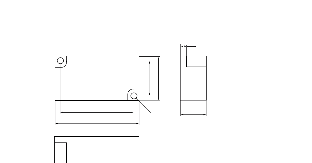
6.4.5 Dimension drawing
7KHWUDQVSRQGHUFDQEHPRXQWHGDVVKRZQZLWK
WKHIL[LQJIUDPH
,QVWDOODWLRQGLDJUDP
)L[LQJIUDPH
7UDQVSRQGHU
Figure 6-9 RF350T dimension drawing
Dimensions in mm
Transponders
6.5 RF360T
SIMATIC RF300
138 System Manual, 06/2008, A5E01642529-02
6.5 RF360T
6.5.1 Features
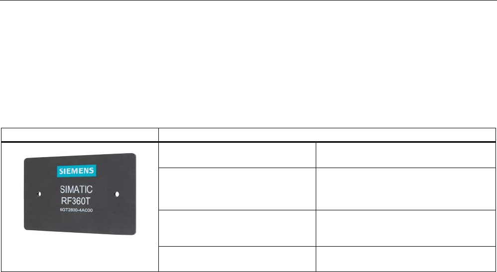
Transponder RF360T Features
Area of application Identification tasks on small assembly lines
in harsh industrial environments
Memory Read-only area (4 bytes UID)
Read/write memory (8 KB)
OTP 1) memory (20 bytes)
Read/write range Refer to SectionField data for
transponders, readers and
antennas (Page 39)
Mounting on metal Not possible; recommended distance from
metal ≥ 20 mm
1) OTP. (One Time Programmable)
Transponders
6.5 RF360T
SIMATIC RF300
System Manual, 06/2008, A5E01642529-02 139
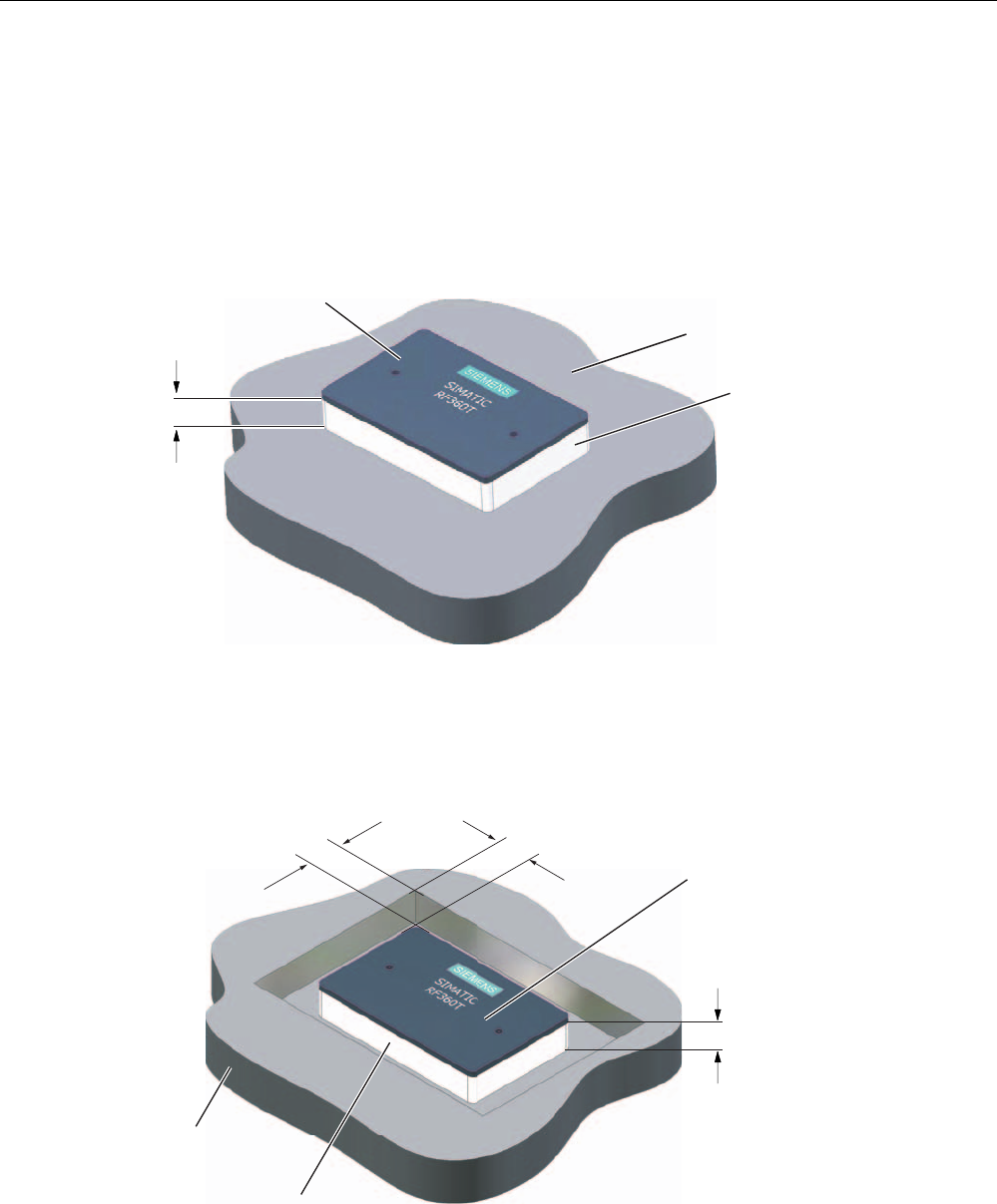
6.5.2 Metal-free area
Direct mounting of the RF360T on metal is not allowed. A distance ≥ 20 mm is
recommended. This can be achieved using the spacer 6GT2190-0AA00 in combination with
the fixing pocket 6GT2190-0AB00.
Mounting of RF360T on metal
K
0HWDO
1RQPHWDO
'DWDVWRUDJHXQLW
Figure 6-10 Mounting of RF360T with spacer
The standard value for h is ≥ 20 mm.
Flush-mounting of RF360T in metal:
1RQPHWDO
0HWDO
D
D
'DWDVWRUDJHXQLW
K
Figure 6-11 Flush-mounting of RF360T with spacer
The standard value for a is ≥ 20 mm. At lower values, the field data change significantly,
resulting in a reduction in the range.
Transponders
6.5 RF360T
SIMATIC RF300
140 System Manual, 06/2008, A5E01642529-02
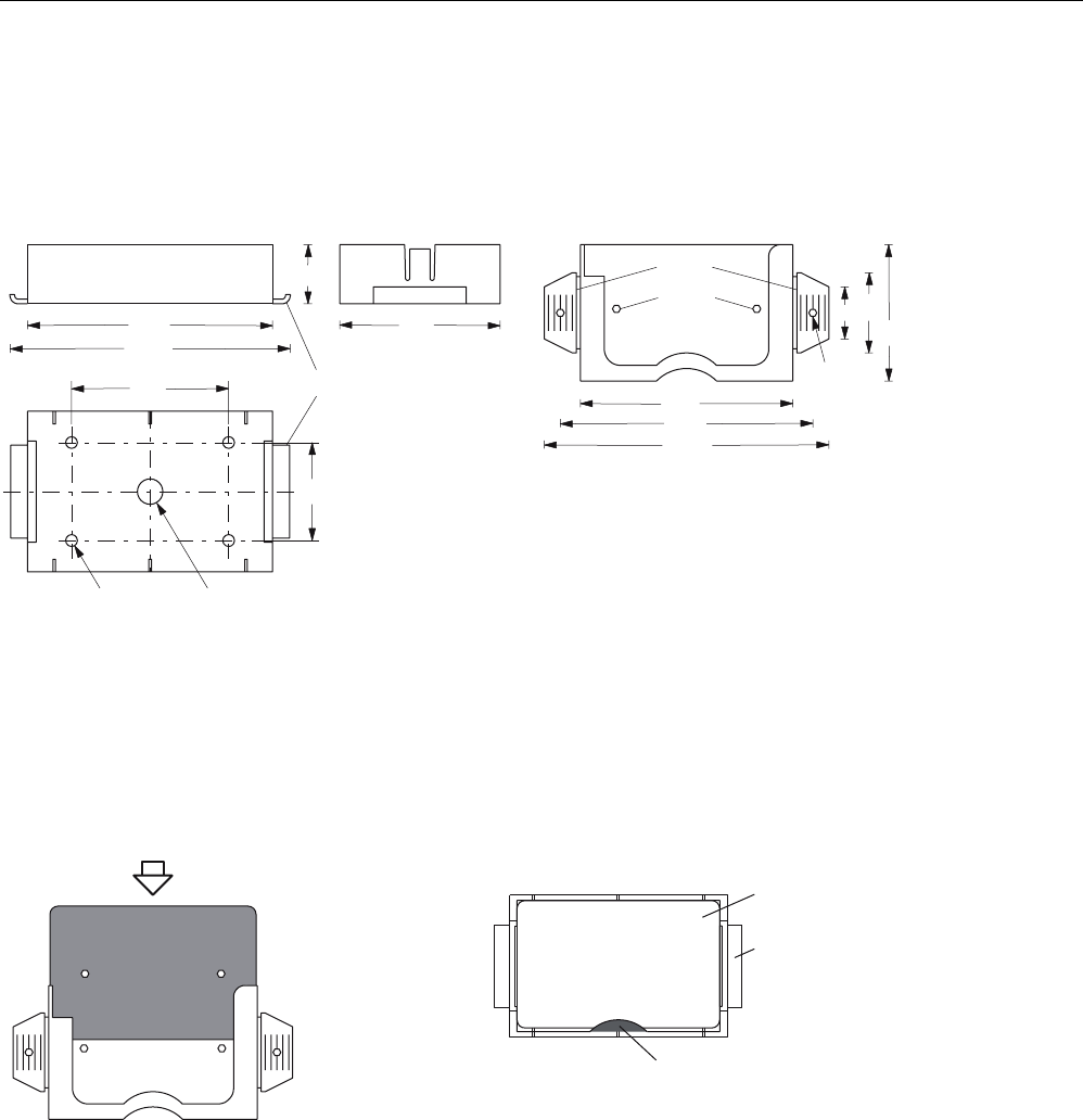
Dimensions of spacer and fixing pocket for RF360T
+ROGLQJFOLS
7KHVSDFHUFDQEHGLUHFWO\PRXQWHGRQPHWDO,QFRPELQDWLRQZLWKWKH
IL[LQJSRFNHWDQRQPHWDOGLVWDQFHRIPPUHVXOWVEHWZHHQWKHWUDQVSRQGHUDQGPHWDO
0RXQWLQJ
:LWKRUVFUHZV0
:LWKUXEEHUVRQWKHKROGLQJFOLSVHJRQPHVKER[HV
:LWKFDEOHWLHVRQWKHKROGLQJFOLSVHJRQPHVKER[HV
(DUV
+ROGLQJNQREV
'LPHQVLRQVNHWFK
6SDFHU*7$$ )L[LQJSRFNHW*7$%
7KHIL[LQJSRFNHWLVDWWDFKHGWRDQRQPHWDO
EDVHE\WKHHDUV7KLVFDQEHDFKLHYHG
ZLWK
6FUHZVLQWKHKROHVSURYLGHG
5LYHWVLQWKHKROHVSURYLGHG
1DLOVWKURXJKWKHKROHV
7DFNVWKURXJKWKHSODVWLFRIWKHHDUV
3XVKLQJLQWRWKHVSDFHUV
7KHHDUVFDQEHPRYHGWKURXJKXSWRr
7KHWUDQVSRQ
GHULV
LQVHUWHGLQWR
WKH
IL[LQJSRFNHW
/RFNLQJLVYLD
WKHKROGLQJ
NQREVLQWKH
IL[LQJSRFNHW 'DWDPHPRU\
6SDFHU
)L[LQJSRFNHW
7KHWUDQVSRQGHULVLQVHUWHGLQWRWKH
IL[LQJSRFNHW7KHHDUVDUHPRYHGE\
rDQGLQVHUWHGLQWRWKHVSDFHU7KH
IL[LQJSRFNHWPXVWEH
DOLJQHGVXFKWKDWLWFRYHUV
WKHWUDQVSRQGHUVHH)LJXUH/RFNLQJ
LVDXWRPDWLF
7UDQVSRQGHUZLWKIL[LQJSRFNHW 7UDQVSRQGHUZLWKIL[LQJSRFNHWDQG
VSDFHUFRQQHFWHGWRJHWKHU
0DWHULDO3$
5HDVVHPEO\LQVWUXFWLRQV
6,(0(16
Figure 6-12 Dimensions of spacer and fixing pocket for RF360T

Transponders
6.5 RF360T
SIMATIC RF300
System Manual, 06/2008, A5E01642529-02 141
6.5.3 Technical data
Table 6-4 Technical specifications for RF360T
Memory size 8 KB
Memory organization Blocks of 8 bits / 1 byte
Memory configuration
• Serial number (UID)
• Application memory
• OTP 1) memory
• 4-byte (fixed code)
• 8189 bytes r/w
• 20 bytes
Storage technology FRAM / EEPROM
MTBF (Mean Time Between Failures) in years 1201
Write cycles, at +40°C Virtually unlimited (>1010)
Read cycles Virtually unlimited (>1010)
Transmission rate
• Reading
• Writing
with RS422 reader:
Approx. 0.3 ms / byte
approx. 0.3 ms / byte
with IQ-Sense reader:
Approx. 20 ms / byte
approx. 25 ms / byte
Data retention > 10 years
Read/write distance dependent on the reader used
(see field data)
Multitag capability max. 4 transponders
Recommended spacing from metal ≥ 20 mm; e.g. using spacer 6GT2190-0AA00 in
conjunction with fixing pocket 6GT2190-0AB00
Power supply Inductive, without battery
Degree of protection to EN 60529
Shock to EN 60721-3-7
Vibration to EN 60721-3-7
Torsion and bending load
IP67
50 g
20 g
Not permitted permanently
Enclosure dimensions
Color
Material
Fixing
85.8 x 54.8 x 2.5 mm (L x W x H)
Anthracite
Epoxy resin
2 screws (M3) or with fixing pocket 6GT2190-
0AB00
Ambient temperature
• During operation
• During transport and storage
-25°C to +75°C
-40°C to +85°C
Weight Approx. 25 g
1) OTP: (One Time Programmable)
Transponders
6.5 RF360T
SIMATIC RF300
142 System Manual, 06/2008, A5E01642529-02
6.5.4 Ordering data
RF360T Order No.
8 KB FRAM (read/write) + 4 byte EEPROM (read
only), IP 67, -25 °C to +75 °C, dimensions 85.8 x
54.8 x 2.5 (LxWxH in mm)
6GT2800-4AC00
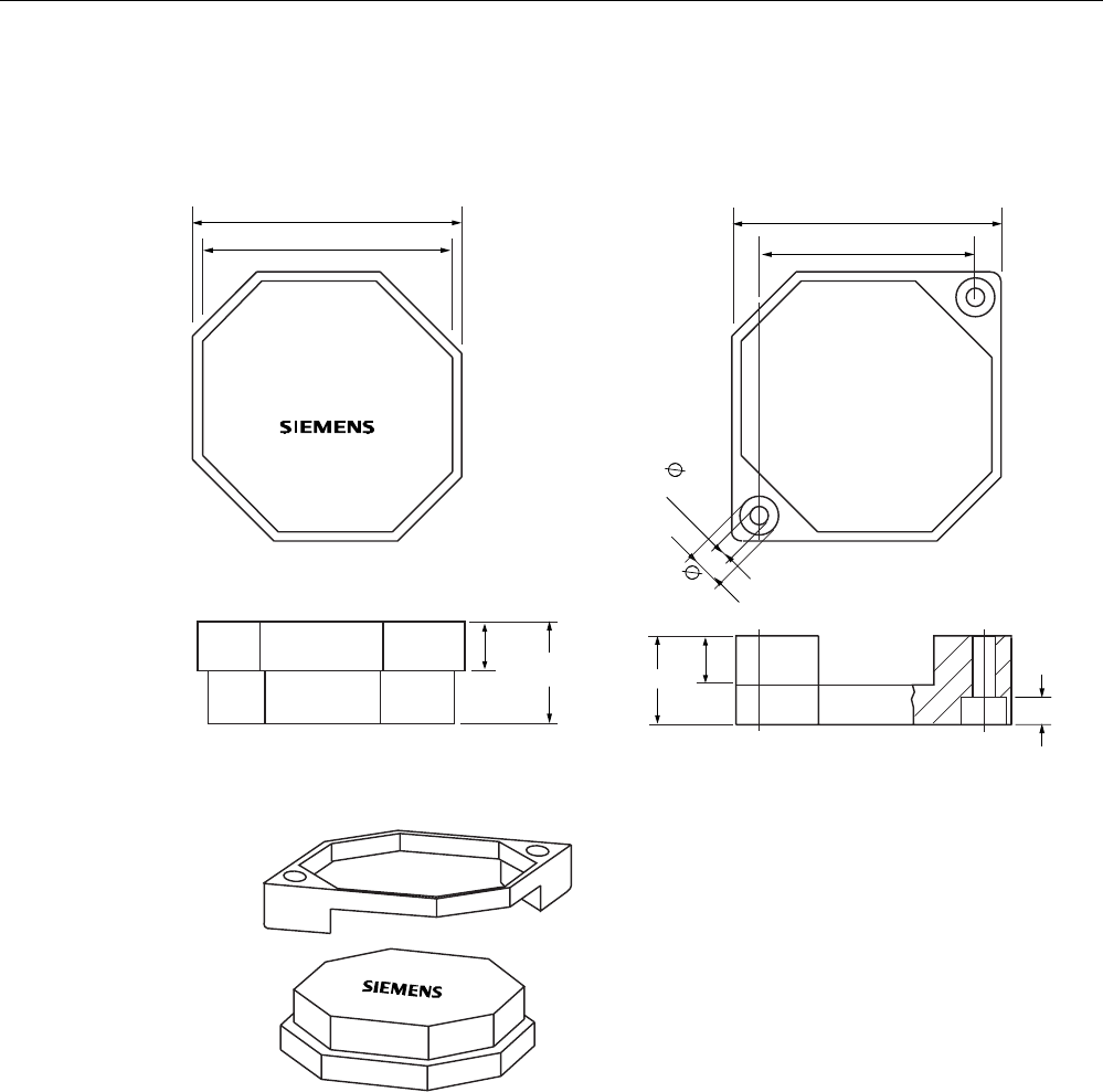
6.5.5 Dimension drawing
5
Figure 6-13 RF360T dimension drawing
Dimensions in mm
Transponders
6.6 RF370T
SIMATIC RF300
System Manual, 06/2008, A5E01642529-02 143
6.6 RF370T
6.6.1 Features
The SIMATIC RF370T transponder is a passive (i.e. battery-free) data carrier in a square
type of construction.
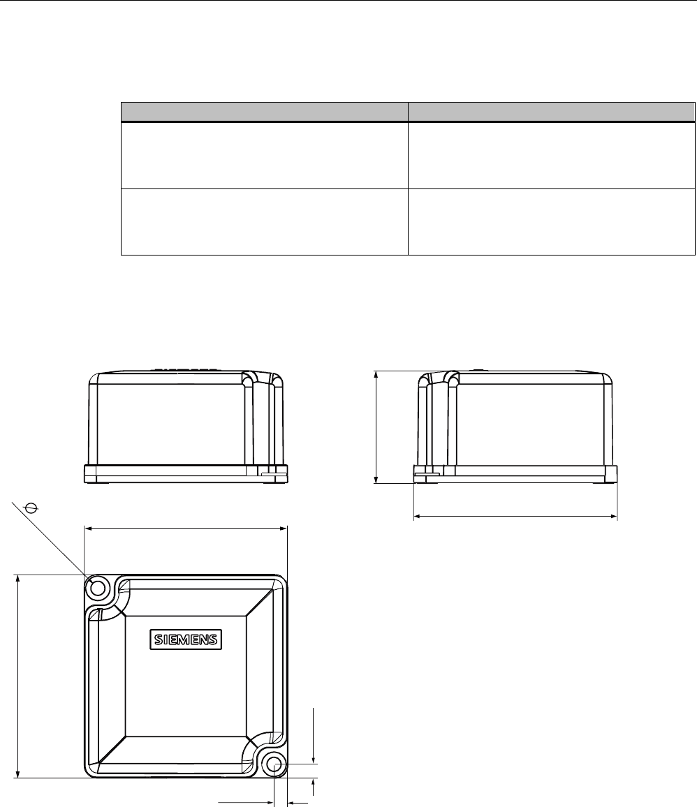
SIMATIC RF370T transponder Features
Area of application Identification tasks on assembly lines in
harsh industrial environments, suitable for
larger ranges,
e.g. automotive industry
Memory Read-only area:
4 byte UID
read/write memory:
32/64 KB
OTP 1) memory: 20 bytes
Read/write range Refer to SectionField data for transponders,
readers and antennas (Page 39)
Assembly Direct assembly on metal or flush-mounting
is possible (with two M5 screws)
Degree of protection IP68
IPx9K
High resistance to mineral oils, lubricants and cleaning
agents
1) OTP: (One Time Programmable)
Transponders
6.6 RF370T
SIMATIC RF300
144 System Manual, 06/2008, A5E01642529-02
6.6.2 Metal-free area
Direct mounting of the RF370T on metal is permitted.
Mounting of RF370T on metal
Figure 6-14 Mounting of RF370T on metal
Flush-mounting of RF370T in metal:
D
D
Figure 6-15 RF370T flush-mounted in metal
The standard value for a is ≥ 20 mm. At lower values, the field data change significantly,
resulting in a reduction in the range.

Transponders
6.6 RF370T
SIMATIC RF300
System Manual, 06/2008, A5E01642529-02 145
6.6.3 Mounting instructions
It is essential that you observe the instructions in the Section Installation
guidelines (Page 57).
Properties Description
Type of installation Screw fixing (two M5 screws)
Tightening torque < 1.2 Nm (at room temperature)

Transponders
6.6 RF370T
SIMATIC RF300
146 System Manual, 06/2008, A5E01642529-02
6.6.4 Technical specifications
6.6.4.1 Technical data for RF370T with 32 KB FRAM
Table 6-5 Technical specifications for RF370T with 32 KB FRAM
Characteristic Description
Memory size 32KB
Memory organization Blocks of 8 bits / 1 byte
Serial number 4-byte (fixed code)
Application memory 32765 bytes r/w
Memory configuration
OTP 1) memory 20 bytes
Storage technology FRAM / EEPROM
MTBF (Mean Time Between Failures)
in years
1189
Write cycles, at +40°C Virtually unlimited (>1010)
Read cycles Practically unlimited (>1010)
Read approx. 0.3 ms/byte Transmission rate
Write approx. 0.3 ms/byte
Data retention in years > 10
Read/write distance dependent on the reader used (see field data)
Multitag capability max. 4 transponders
Recommended spacing from metal can be directly mounted on metal
Power supply Inductive, without battery
Degree of protection to EN 60529 IPx9K
Shock resistant to EN 60721-3-7 50 g
Vibration resistant to EN 60721-3-7 20 g
Torsion and bending load Not permissible continuously
Housing dimensions 75 x 75 x 40 mm (L x W x H)
Color Anthracite
Material PA12
Fixing Two M5 screws
During operation -25 °C to +85 °C Ambient temperature
During transport and storage -40°C to +85°C
Weight Approx. 200 g
1) OTP: One Time Programmable; single write

Transponders
6.6 RF370T
SIMATIC RF300
System Manual, 06/2008, A5E01642529-02 147
6.6.4.2 Technical data for RF370T with 64 KB FRAM
Table 6-6 Technical specifications for RF370T with 64 KB FRAM
Characteristic Description
Memory size 64 KB
Memory organization Blocks of 8 bits / 1 byte
Serial number 4-byte (fixed code)
Application memory 65276 bytes r/w
Memory configuration
OTP 1) memory 20 bytes
Storage technology FRAM / EEPROM
MTBF (Mean Time Between Failures)
in years
1189
Write cycles, at +40°C Practically unlimited (>1010)
Read cycles Practically unlimited (>1010)
Read approx. 0.3 ms/byte Transmission rate
Write approx. 0.3 ms/byte
Data retention in years > 10
Read/write distance dependent on the reader used (see field data)
Multitag capability max. 4 transponders
Recommended spacing from metal Can be directly mounted on metal
Power supply Inductive, without battery
Degree of protection to EN 60529 IPx9K
Shock resistant to EN 60721-3-7 50 g
Vibration resistant to EN 60721-3-7 20 g
Torsion and bending load Not permissible continuously
Housing dimensions 75 x 75 x 40 mm (L x W x H)
Color Anthracite
Material PA12
Fixing Two M5 screws
During operation -25 °C to +85 °C Ambient temperature
During transport and storage -40°C to +85°C
Weight Approx. 200 g
1) OTP: One Time Programmable, single write
Transponders
6.6 RF370T
SIMATIC RF300
148 System Manual, 06/2008, A5E01642529-02
6.6.5 Ordering data
Ordering data Order No.
SIMATIC RF300
RF370T transponder
32 KB FRAM, -25 to +85 degrees C,
IP68; 75 x 75 x 40 mm
6GT2800-5BE00
SIMATIC RF300
RF370T transponder
64 KB FRAM, -25 to +85 degrees C,
IP68; 75 x 75 x 40 mm
6GT2800-6BE00
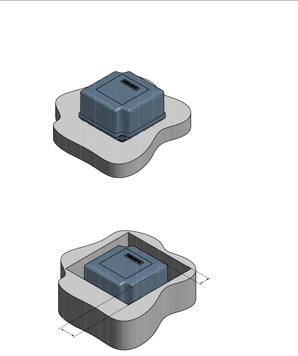
6.6.6 Dimensional drawing
Figure 6-16 RF370T dimension drawing
Dimensions in mm (inches in brackets)
Transponders
6.7 RF380T
SIMATIC RF300
System Manual, 06/2008, A5E01642529-02 149
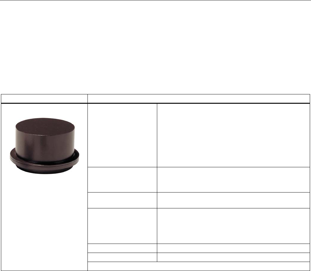
6.7 RF380T
6.7.1 Features
The SIMATIC RF380T transponder is an extremely rugged and heat-resistant round data
carrier suitable e.g. for applications in the automotive industry.
SIMATIC RF380T transponder Features
Area of application Identification tasks in applications (e.g. automotive industry)
with cyclic high temperature stress > 85 °C and < 220 °C
Typical applications:
• Primer coat, electrolytic dip area, cataphoresis with the
associated drying furnaces
• Top coat area with drying furnaces
• Washing areas at temperatures > 85°C
• Other applications with higher temperatures
Memory • Read-only area (4 bytes UID)
• Read/write memory (32 KB)
• OTP 1) memory (20 bytes)
Write/read range Refer to SectionField data for transponders, readers and
antennas (Page 39)
Assembly • Direct assembly on metal or flush-mounting is possible.
• The transponder can be secured using a special holder
(see installation guidelines, section on RF380T).
The tag size is designed such that it can be secured on
a skid or also directly on a body.
Degree of protection IP 68
High resistance to mineral oils, lubricants and cleaning agents
1) OTP: One Time Programmable
6.7.2 Installation guidelines for RF380T
It is essential that you observe the instructions in the Section Installation
guidelines (Page 57).
The following section only deals with features specific to the SIMATIC RF380T.
Transponders
6.7 RF380T
SIMATIC RF300
150 System Manual, 06/2008, A5E01642529-02
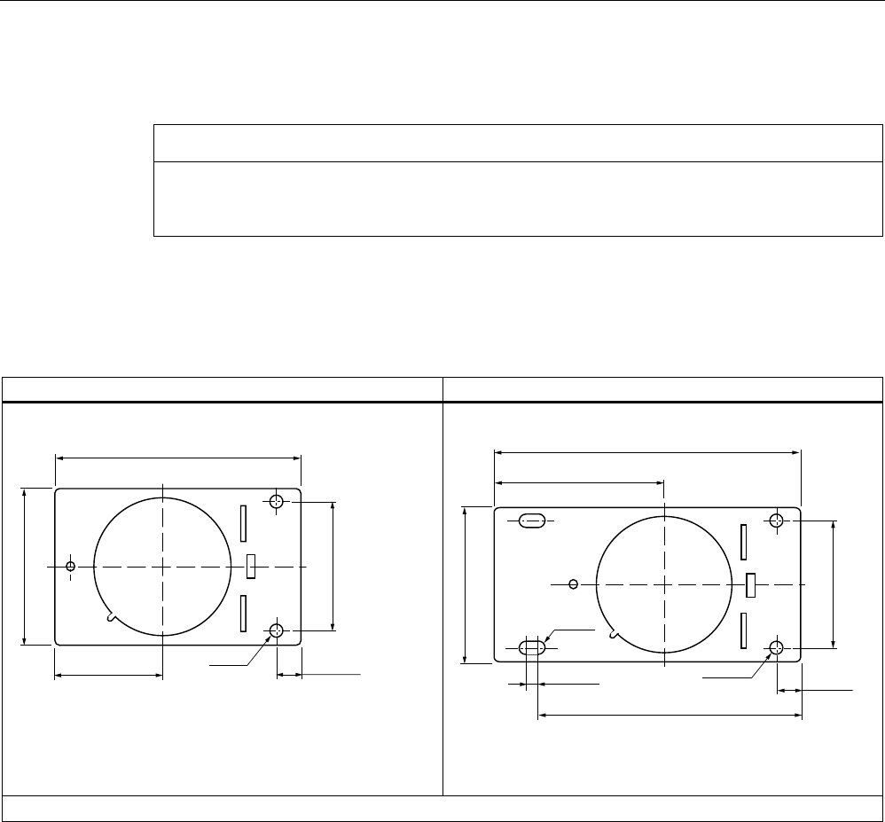
6.7.2.1 Mounting instructions
CAUTION
You are strongly recommended to only use the tag with the original holder specified. Only
this holder guarantees that the data memory observes the listed values for shock, vibration
and temperature. A protective cover is recommendable for applications in paint shops.
Data memory support
Short version (6GT2 090-0QA00) Long version (6GT2090-0QA00-0AX3)
Dimensions in mm, inches in brackets
Dimensions in mm, inches in brackets
Material: V2A sheet-steel with thickness 2.5 mm BI 2.5 DIN 59382 1.4541
Transponders
6.7 RF380T
SIMATIC RF300
System Manual, 06/2008, A5E01642529-02 151
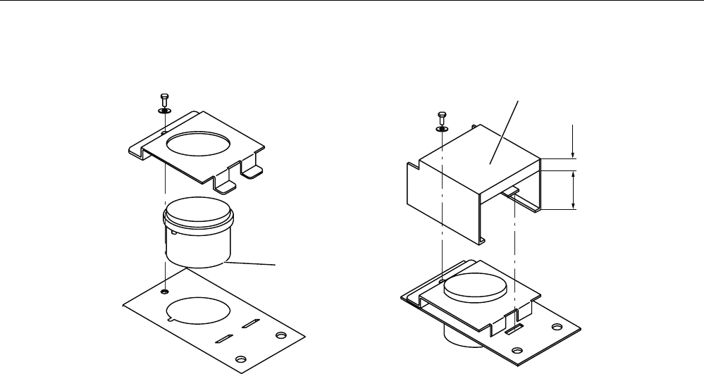
Assembly of data memory with support
$QWHQQDVLGHRIWDJ
&RYHURSWLRQDO
*74%
Figure 6-17 Assembly of tag with support
Scope of supply
The support is provided with all mounting parts and a mounting diagram. Mounting screws
for securing the support are not included. The mounting screws are of diameter M 10. The
minimum length is 25 mm. The optional cover can be used for the long and short versions of
the support.
Transponders
6.7 RF380T
SIMATIC RF300
152 System Manual, 06/2008, A5E01642529-02
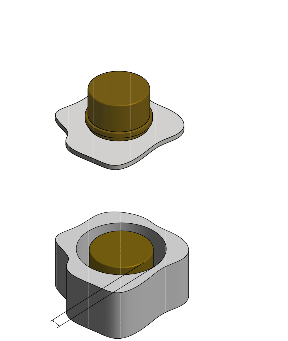
6.7.2.2 Metal-free area
Direct mounting of the RF380T on metal is permitted.
Mounting of RF380T on metal
Figure 6-18 Mounting of RF380T on metal
Flush-mounting of RF380T in metal:
D
Figure 6-19 RF380T flush-mounted in metal
The standard value for a is ≥ 40 mm. At lower values, the field data change significantly,
resulting in a reduction in the range.
Transponders
6.7 RF380T
SIMATIC RF300
System Manual, 06/2008, A5E01642529-02 153
6.7.3 Configuring instructions
6.7.3.1 Temperature dependence of the transmission window
The guidelines in Section "Planning the RF300 system" apply to configuration of heat-
resistant data memories, with the exception of the limit distance and field length at
temperatures above 85 °C.
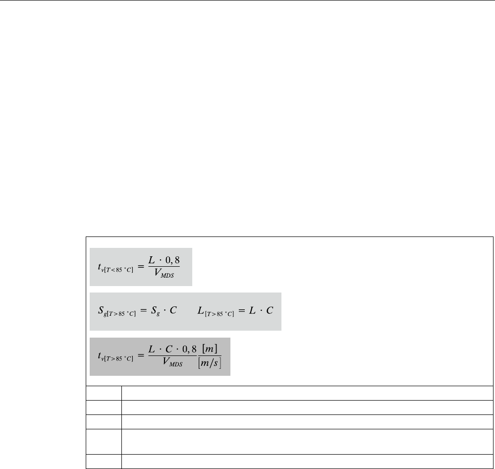
Calculation of transmission window with heat-resistant data memories
The factor 0.8 is required for calculating the transmission window, and takes into account
production tolerances and temperature influences of to 85 °C.
An additional correction factor C must be included in the calculation at temperatures > 85 °C
(up to 110 °C):
L Field length
Sg Limit distance tag - reader
VTag Tag speed
C Correction factor at temperatures > 85 °C
(cf. following picture with correction factor C depending on temperature)
tv Tag dwell time
Transponders
6.7 RF380T
SIMATIC RF300
154 System Manual, 06/2008, A5E01642529-02
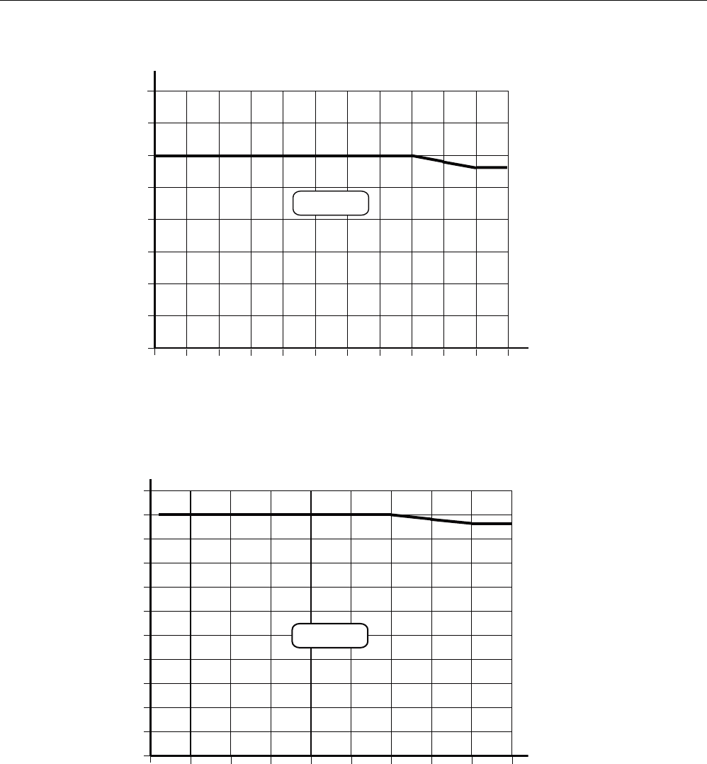
&>FRUUHFWLRQIDFWRU@
7>r&@
5)7
Figure 6-20 Correction factor C depending on temperature
The following diagram shows the reduction in the limit distance and field length at increased
processing temperatures (internal temperature of tag):
,QWHUQDOWHPSHUDWXUH>r&@
5)7
>@
Figure 6-21 Reduction in field length and limit distance
The reduction in the field data at higher temperatures is due to the increased current
consumption of the electronics.

Transponders
6.7 RF380T
SIMATIC RF300
System Manual, 06/2008, A5E01642529-02 155
6.7.3.2 Temperature response in cyclic operation
At ambient temperatures (Tu) up to 110 °C, cyclic operation is not necessary, i.e. up to this
temperature, the transponder can be in constant operation.
Note
Calculation of the temperature curves
Calculation of the temperature curves or of a temperature profile can be carried out on
request by Siemens AG. Exact knowledge of the internal temperature facilitates
configuration for time-critical applications.
Ambient temperatures > 110 °C
NOTICE
Cancellation of warranty
The internal temperature of the data memory must not exceed the critical threshold of 110
°C. Each heating phase must be followed by a cooling phase. No warranty claims will
otherwise be accepted.
Some limit cycles are listed in the table below:
Table 6-7 Limit cycles of data memory temperature
Tu (heating up) Heating up Tu (cooling down) Cooling down
220 °C 0.5 h 25 °C > 2 h
200 °C 1 h 25 °C > 2 h
190 °C 1 h 25 °C > 1 h 45 min
180 °C 2 h 25 °C > 5 h
170 °C 2 h 25 °C > 4 h
The internal temperature of the tag follows an exponential function with which the internal
temperature and the operability of the tag can be calculated in advance. This is particularly
relevant to temperature-critical applications or those with a complex temperature profile.
Ambient temperatures > 220°C
NOTICE
Cancellation of warranty
The data memory must not be exposed to ambient temperatures > 220 °C. No warranty
claims will otherwise be accepted.
However, the mechanical stability is retained up to 230 °C!
Transponders
6.7 RF380T
SIMATIC RF300
156 System Manual, 06/2008, A5E01642529-02
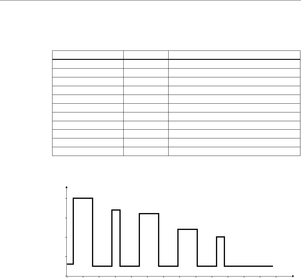
Example of a cyclic sequence
Table 6-8 Typical temperature profile of an application in the paint shop
Start of tag at initial point Duration (min) Ambient temperature (°C)
Electrolytic dip 20 30
Electrolytic dip dryer 60 200
Transport 60 25
PVC dryer 25 170
Transport 60 25
Filler dryer 60 160
Transport 60 25
Top coat dryer 60 120
Transport 60 25
Wax dryer 25 100
Transport 150 25
7HPSHUDWXUH
.7/EDWK
7LPH
.7/GU\HU
39&GU\HU )LOOHUGU\HU
7RSFRDW
GU\HU :D[GU\HU
>PLQ@
>r&@
Figure 6-22 Graphic trend of temperature profile from above table
Transponders
6.7 RF380T
SIMATIC RF300
System Manual, 06/2008, A5E01642529-02 157
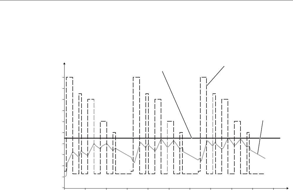
The simulation results in the following:
Following a simulation time of 36.5 hours, a total of 3 cycles were carried out, and an internal
temperature of 90 degrees Celsius was reached.
7HPSHUDWXUH
7LPH
$PELHQWWHPSHUDWXUH
0D[LPXPLQWHUQDOWHPSHUDWXUHRI
WDJIRUWKLVH[DPSOH
,QWHUQDO
WHPSHUDWXUH
RIWDJ
>PLQ@
>r&@
Figure 6-23 Complete temperature response due to simulation

Transponders
6.7 RF380T
SIMATIC RF300
158 System Manual, 06/2008, A5E01642529-02
6.7.4 Technical specifications
Table 6-9 RF380T with 32 KB FRAM
Characteristic Description
Memory size 32KB
Memory organization Blocks of 8 bits / 1 byte
Serial number 4-byte (fixed code)
Application memory 32765 bytes r/w
Memory configuration
OTP 1) memory 20 bytes
Storage technology FRAM / EEPROM
MTBF (Mean Time Between Failures)
in years
1177
Write cycles, at +40°C Virtually unlimited (>1010)
Read cycles Virtually unlimited (>1010)
Read approx. 0.3 ms/byte Transmission rate
Write approx. 0.3 ms/byte
Data retention > 10 years
Write/read distance dependent on the reader used (see field data)
Multitag capability max. 4 transponders
Recommended spacing from metal can be directly mounted on metal
Power supply Inductive, without battery
Degree of protection to EN 60529 IP68
Shock resistant2) to EN 60721-3-7 50 g
Vibration2) to EN 60721-3-7 5 g
Direction-dependent No
Torsion and bending load Not permissible continuously
Enclosure dimensions (diam. x H in mm) 114 x 83
Color Brown
Material PPS
Fixing Support to be ordered separately
During operation -25 °C to +110°C
During cyclic operation -25 °C to +220°C
Ambient temperature
During transport and storage -40°C to +110°C
Weight Approx. 900 g
1) OTP: (One Time Programmable)
2) Applies only in connection with original bracket
Transponders
6.7 RF380T
SIMATIC RF300
System Manual, 06/2008, A5E01642529-02 159
6.7.5 Ordering data
RF380T/
accessories
Order No.
• Operating temperature -25 to +200 °C (cyclic)
• Dimensions (diam. x H in mm) 114 x 83
• IP 68 degree of protection
• 32 KB FRAM (read/write) + 4 byte EEPROM
6GT2800-5DA00
Accessories
• Support (short version)
• Support (long version)
• Covering hood
6GT2090-0QA00
6GT2090-0QA00-0AX3
6GT2090-0QB00
6.7.6 Dimensional drawing
SIEMENS
6HFXULQJERUGHU
$QWHQQDHQG
Figure 6-24 Dimension drawing RF380T
Dimensions in mm (inches in brackets)
Transponders
6.8 Memory configuration of the RF300 tags
SIMATIC RF300
160 System Manual, 06/2008, A5E01642529-02
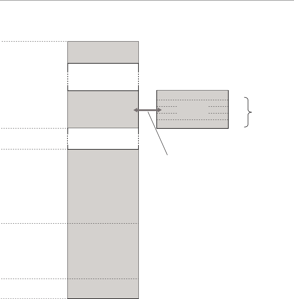
6.8 Memory configuration of the RF300 tags
5)7
5)7
5)7
5)7
5)7
5)7
E\WHV
8,'UHDGRQO\
E\WHV
8VHUDUHD
UHDGZULWH
)5$0
8VHUDUHD
UHDGZULWH
((3520
273
QRWZLWK
,46HQVH
)))
)))
))
))
))&
)()&
))&
))
))&
))
))
))
3K\VLFDOO\LGHQWLFDOPHPRU\
:KHQWKH273DUHDLVXVHGWKH
FRUUHVSRQGLQJXVHUDUHD))
))FDQQRORQJHUEHPRGLILHG
UHDGRQO\
PD[
EORFNVRI
E\WHVHDFK
5)7.%
5)7.%
5)7.%
5)7.%
5)7.%
5)7.%
Figure 6-25 Memory configuration of the RF300 tags

Transponders
6.8 Memory configuration of the RF300 tags
SIMATIC RF300
System Manual, 06/2008, A5E01642529-02 161
Memory areas
The memory configuration of an RF300 tag always comprises an EEPROM memory that has
20 bytes for user data (read/write) and a 4 byte unique serial number (UID, read only). For
reasons of standardization, the UID is transferred as an 8 byte value through a read
command to address FFF0 with a length of 8. The unused 4 high bytes are filled with zeros.
A high-speed FRAM memory (read/write) is available as an option. Depending on the tag
type, this is 8 KB (0-1FFC) or 32 KB (0-7FFC) in size.
The EEPROM memory area (address FF00-FF13) can also be used as a so-called "OTP"
memory (One Time Programmable). The 5 block addresses FF80, FF84, FF88, FF8C and
FF90 are used for this purpose. A write command to this block address with a valid length (4,
8, 12, 16, 20 depending on the block address) protects the written data from subsequent
overwriting.
NOTICE
This operation is not reversible.
OTP area
Note
The OTP area cannot be used for the IQ-Sense reader variant.
When the OTP area is used, it must be ensured that the blocks are used starting from Block
0 consecutively.
Examples:
3 blocks (with write command), Block 0, 1, 2 (FF80, length = 12): valid
2 blocks (consecutive), Block 0 (FF80, length =4), Block 1 (FF84, length = 4): valid
2 blocks (consecutive), Block 0 (FF80, length =4), Block 2 (FF88, length = 4): Invalid
1 Block, Block 4 (FF90, length = 4): Invalid
The EEPROM user memory (address FF00-FF13, or FF80-FF90) requires significantly more
time for writing (approx. 11 ms/byte) than the high-speed FRAM memory. For time-critical
applications with a write function, it is therefore recommended that FRAM tags are used (e.g.
RF340T, RF350T, RF360T).

Transponders
6.8 Memory configuration of the RF300 tags
SIMATIC RF300
162 System Manual, 06/2008, A5E01642529-02
SIMATIC RF300
System Manual, 06/2008, A5E01642529-02 163
Communication modules 7
7.1 Overview
The communication modules (interface modules) are links between the RFID components
(reader and transponder) and the higher-level control systems (e.g. SIMATIC S7) or PC or
computers.
Communication modules
7.2 8xIQ-Sense
SIMATIC RF300
164 System Manual, 06/2008, A5E01642529-02
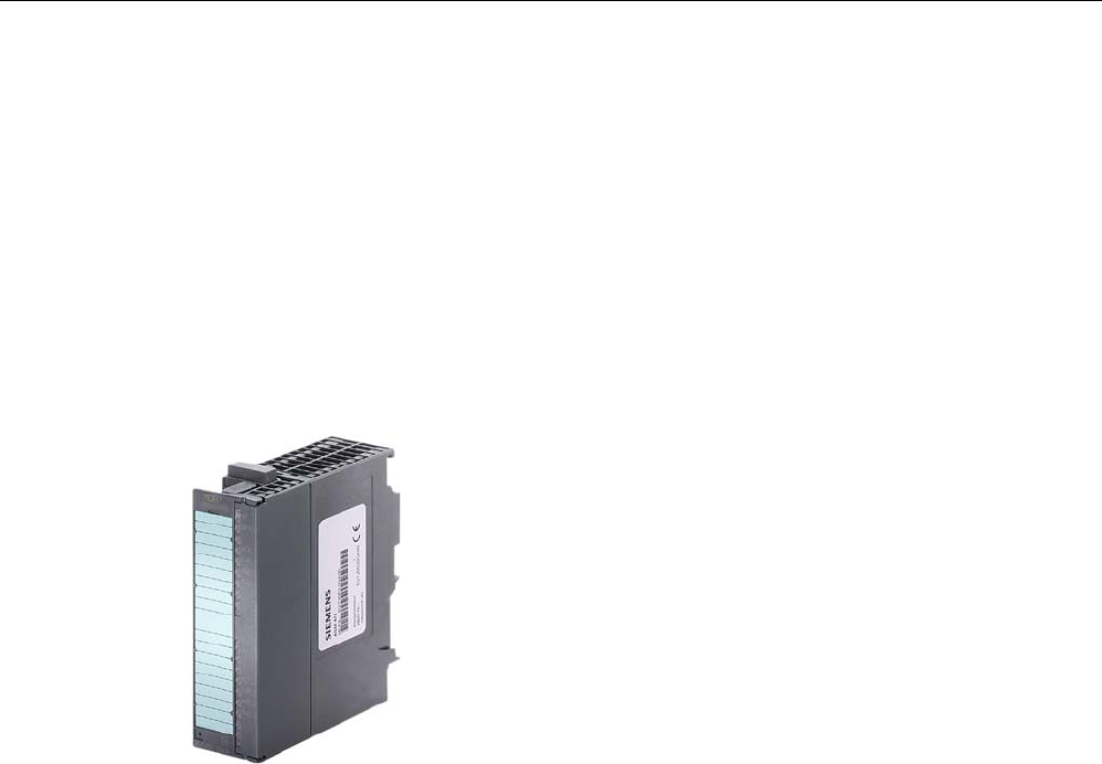
7.2 8xIQ-Sense
7.2.1 Features
Field of application
The 8xIQ-Sense module is the link between the RF310R with 8xIQ-Sense interface and
SIEMENS S7-300 and functions in the same manner as the communication module
(interface module). It can be operated centrally in an S7-300 or decentrally in an ET200M.
Figure 7-1 8xIQ-Sense interface module
Communication modules
7.2 8xIQ-Sense
SIMATIC RF300
System Manual, 06/2008, A5E01642529-02 165
7.2.2 Indicators
Status displays
The 8xIQ-Sense module has the following LEDs:
A green LED, which has no function for RFID devices, and a red SF LED (system fault LED),
which indicates the diagnostic state of the module.
LEDs Labeling LED
status
Meaning
Green
LED per
channel
0…7 Has no function here
Illuminate
d
Module fault, sensor fault,
active teach-in operation,
external auxiliary voltage
missing
6)
60
[,46HQVH
;)$%
;
Red SF
Not
illuminate
d
No fault or no active teach-in
operation
Communication modules
7.2 8xIQ-Sense
SIMATIC RF300
166 System Manual, 06/2008, A5E01642529-02
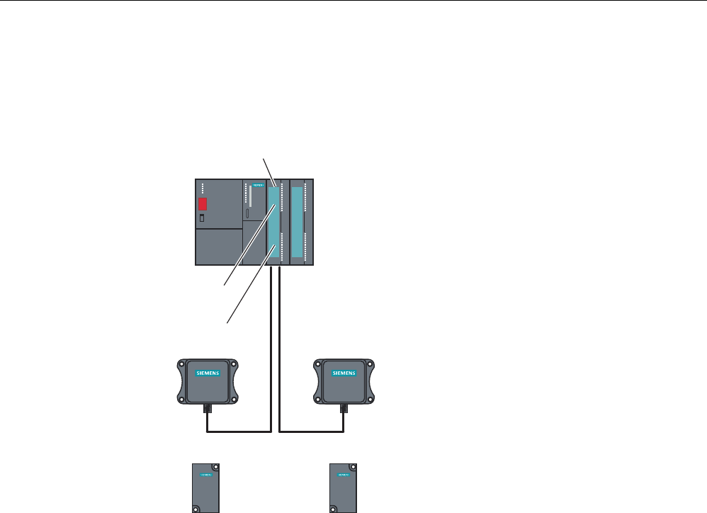
7.2.3 Configuration
Centralized configuration with SIMATIC S7-300
6,0$7,&
5)5
6,0$7,&
5)5
6,0$7,&
5)7
6,0$7,&
5)7
2WKHUPRGXOHVIURPWKH6UDQJH
LQFOXGLQJ[,46HQVH
$60FKDQQHO
5HDGHUZLWK[,46HQVH
LQWHUIDFH
5HDGHU5HDGHU
7UDQVSRQGHU7UDQVSRQGHU
[,46HQVH
6
Figure 7-2 RF310R reader with 8xIQ-Sense interface
Communication modules
7.2 8xIQ-Sense
SIMATIC RF300
System Manual, 06/2008, A5E01642529-02 167
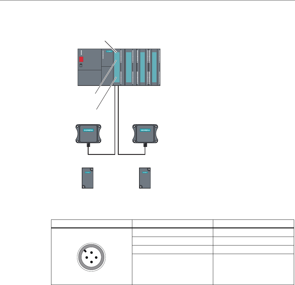
Distributed configuration with ET 200M
6,0$7,&
5)5
6,0$7,&
5)5
6,0$7,&
5)7
6,0$7,&
5)7
2WKHUPRGXOHVIURPWKH6UDQJH
LQFOXGLQJ[,46HQVH
$60FKDQQHO
5HDGHUZLWK[,46HQVH
LQWHUIDFH
5HDGHU5HDGHU
7UDQVSRQGHU7UDQVSRQGHU
[,46HQVH
(70
Figure 7-3 RF310R reader with 8xIQ-Sense interface
Table 7-1 Pin assignment of RF310R with IQ-Sense interface
Pin Pin, device end, 4-pin M12 Assignment
1 IQ-Sense
2 Not assigned
3 IQ-Sense
4 Not assigned
Communication modules
7.2 8xIQ-Sense
SIMATIC RF300
168 System Manual, 06/2008, A5E01642529-02
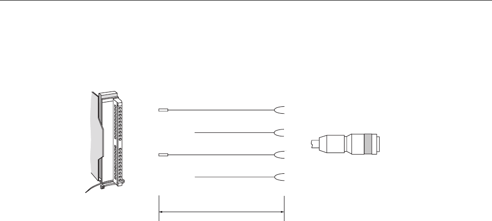
Configuration of connecting cable from 8xIQ-Sense to RF310R
PD[P
6/*FRQQHFWRU
0VRFNHW
5HDGHUVLGH
,46HQVHVLGH
EURZQ
EOXH
Figure 7-4 Cable and pin assignment of RF300 with IQ-Sense
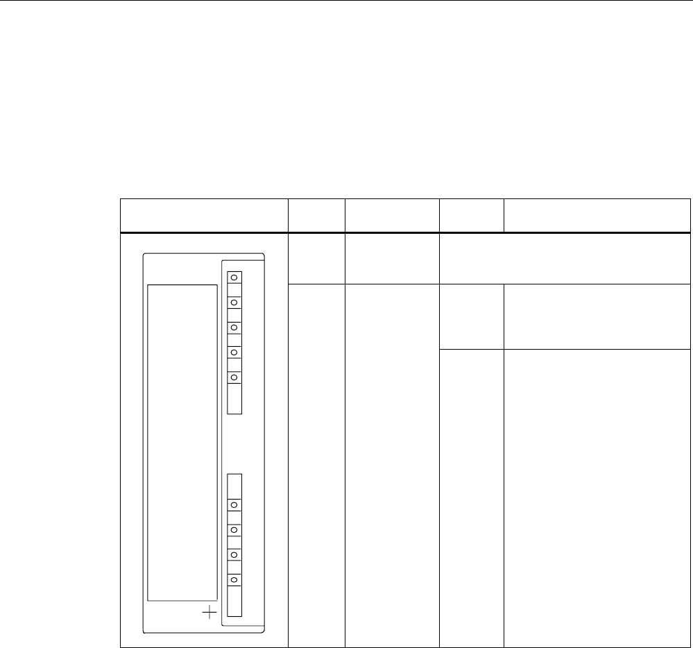
7.2.4 Addressing
The address range of the 8xIQ-Sense module is 16 bytes I/O.
This is independent of the choice of channel profiles on the connected device
(i.e. the IQ profile IDs in HW Config).
Access to memory areas
A direct association exists between the number of the channel to which the IQ-Sense device
is connected (terminal) and the input and output data area of the module. Based on the
address range, the following addresses can be used to access the memory areas:
Address = module initial address + (channel no. x 2)
Communication modules
7.2 8xIQ-Sense
SIMATIC RF300
System Manual, 06/2008, A5E01642529-02 169
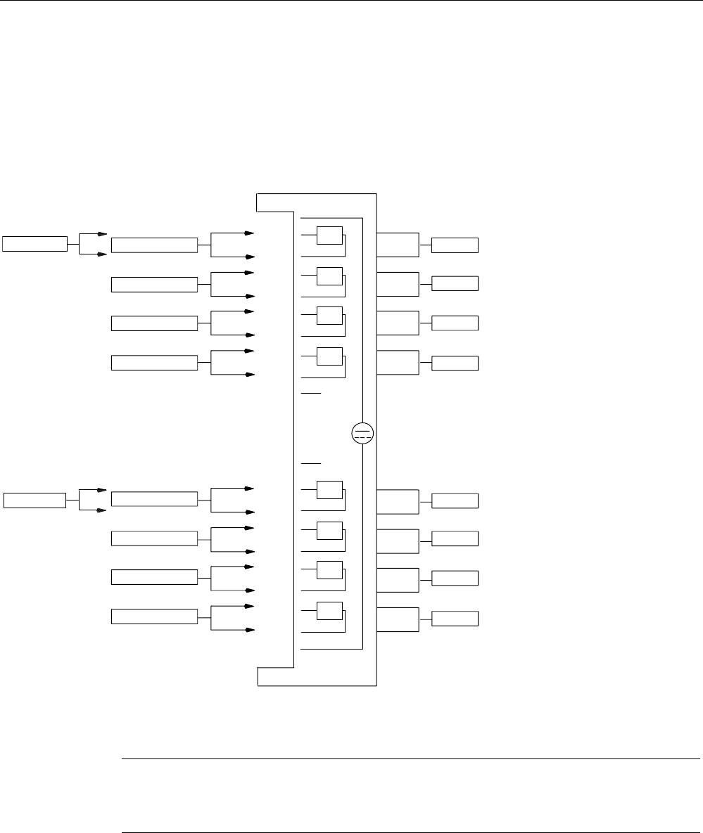
Example
Module initial address = 280
I/O address for channel 3: 286
,46HQVHGHYLFH
0
0ದ
0
0ದ
0
0ದ
0
0ದ
0
0ದ
0
0ದ
0
0ದ
0
0ದ
)URQW GRRULQWHULRU
FKDQQHO
7HUPLQDO
&KDQQHODGGUHVVHV
LQH[DPSOH
IRU,46HQVHGHYLFHV
&KDQQHOQR
FKDQQHO
FKDQQHO
FKDQQHO
FKDQQHO
FKDQQHO
FKDQQHO
FKDQQHO
,4
,4
,4
,4
,4
,4
,4
,4
/
0
IRU5)
,46HQVHGHYLFH
,46HQVHGHYLFH
,46HQVHGHYLFH
,46HQVHGHYLFH
,46HQVHGHYLFH
,46HQVHGHYLFH
,46HQVHGHYLFH
5)5
5)5
Figure 7-5 8xIQ-Sense module: Assignment of terminal pair to memory area
Note
A maximum of two read/write devices can be operated!
Each read/write device uses channel numbers 0 to 3 or 4 to 7.

Communication modules
7.2 8xIQ-Sense
SIMATIC RF300
170 System Manual, 06/2008, A5E01642529-02
7.2.5 Technical data
Voltages and currents
Rated supply voltage
Reverse polarity protection
24 V DC
yes
Galvanic isolation
• Between the channels
• Between channels and backplane bus
no
yes
Permissible potential difference
Between different circuits
75 V DC / 60 V AC
Insulation tested at 500 V DC
Current input
• from the backplane bus
• from L+ power supply
120 mA typical
500 mA max.
Module power loss 2.5 W typical
Module-specific data
Number of channels
Channels for RFID systems
8
2
Cable length, unshielded 50 m max.
Dimensions and weight
Dimensions w x h x d (mm) 40 x 125 x 120
Weight Approx. 235 g
7.2.6 Ordering data
Table 7-2 Ordering data for 8xIQ-Sense and accessories
Product description Order No.
SIMATIC S7-300
IQ-Sense SM338 for S7-300 and ET200M for the
connection of up to 8xIQ-Sense sensors
Optical sensors, ultrasonic sensors and RF
identification systems can be connected.
6ES7 3387XF000AB0
Accessories
M12 cable plug, 4-pole, with 5 m black PUR
cable, 4 x 0.34 mm2
3RX8000-0CB42-1AF0
M12 cable plug, 4-pole, with 10 m black PUR
cable, 4 x 0.34 mm2
3RX8000-0CB42-1AL0